1
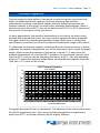
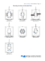
Page 2 · 207 LaserMount User’s Manual Table of Contents Introduction ............................................................................................... 3 Installation and Use................................................................................... 4 Connector Pin-Outs .................................................................................. 8 Technical Specifications ......................................................................... 10 Thermal Capacity .................................................................................... 11 Using the Thermistor on Standard Versions ........................................... 12 Using the RTD on 150°C Versions .......................................................... 13 Mechanical Specifications ...................................................................... 15 Laser Diode Protection............................................................................ 20 Warranty .................................................................................................. 21 Service and Support ............................................................................... 21 207 LaserMount User’s Manual · Page 3 Introduction Thank you for choosing the 207 LaserMount from Arroyo Instruments. The LaserMount is designed for high performance and long term use, with innovative features not found in other mounts. With the integrated fan, selectable thermistor input, and quick disconnect interface, the 207 is an excellent choice for medium power laser and LED applications. The 207 is a smaller version of the more powerful 264 LaserMount. With 12W of thermal capacity, the 207 works well with many fiber pigtailed lasers operating in the 5W to 10W optical power range. The standard cold plate accepts lasers from several different manufacturers, including JDSU, Alfalight, Lumics, and others, and custom mounting options are available. The 207 also works with 200-TRAY fiber management tray and 200-C cover. The fiber management tray provides an elegant solution for managing excess fiber without the use of clips or ties, while the cover improves the thermal stability of the system by insulating the device and cold plate from air drafts. Connecting your device is easy through the use of a pluggable interface, allowing you to permanently connect the laser and TEC cables to the mount, and use a simple quick-disconnect fitting to make the connection to the device. The LaserMount also offers all the features you would expect from a modern laser diode fixture, including: Designed to be quickly integrated with Arroyo’s LaserSource and TECSource instruments. Industry-standard D-sub connectors and pin-outs allow for quick integration into existing laser applications. Optional fiber management tray (p/n 200-TRAY) for managing excess fiber pigtail(s). Optional cover (p/n 200-COVER), when improves the temperature stability of the system. Additional quick disconnect plugs (p/n 1202). Page 4 · 207 LaserMount User’s Manual Installation and Use Wiring the connector to your device The 207 uses a removable connector to make the connection between your device and the mount. Depending on the type of connections you have for your device, you many use some or all of the terminals. Quick Disconnect Plug The 207 comes with one plug. Additional plugs are available from Arroyo Instruments (part number 1202), and we also offer pre-wired connector assemblies for many common lasers. Wired for JDSU L4 Laser Arroyo Instruments offers several different wiring harnesses for many popular lasers from JDSU, LaserTel, Alfalight, Lumics, and others. Contact Arroyo Instruments for assistance in selecting the appropriate wire harness. The quick disconnect plug has screw terminals for each position. Simply strip off about ¼” of each wire’s insulation, insert into the appropriate position, and tighten the screw. 207 LaserMount User’s Manual · Page 5 Devices with Internal Temperature Sensors Some lasers include an internal temperature sensor (typically a thermistor). It is possible to use the device’s internal sensor rather than the sensor in the 207, which will typically provide a higher degree of accuracy and stability. On the back of the mount, there is a SENSOR switch with two positions: INT and EXT. The INT position selects the thermistor in the 207, while the EXT position selects the sensor wired to the S+ and S- connections of the quick disconnect interface. NOTE Earth Grounding Considerations The DB-9 and DB-15 connectors are electrically connected to the housing and 8mm banana jack. Depending on the wiring of your cables and instruments, this may or may not provide earth grounding of the fixture. Make sure the cable shell is earth grounded on both ends of the cable, and that the instrument makes connection from its connector to earth ground. If in doubt, you can also use a grounding strap from the 8mm banana jack directly to earth ground. Powering the Fan If you will be using the 5300 Series TECSource temperature controller to power the fan, make sure to use 1260B or 1262 cable, which has the additional connections for the fan power supply. Otherwise, you can use a 12V DC external power supply with a 2.1mm round DC power jack (center positive). It is possible to operate the fan as low as 6.5V if you would like to reduce the fan noise or vibration, but low fan speeds will reduce the thermal capacity of the mount. For lower power lasers, the fan may not even be required. Using the Optional Fiber Management Tray The 207 supports an optional fiber management tray (p/n 200-TRAY), which makes managing excess fiber much simpler by providing a protected area to coil the fiber. Unlike other solutions that use ties to retain the fiber, our fiber tray has an upper lip that catches the fiber, retaining it gently without needing any ties. To install the tray, simply use the provided screws. Note that if you will be using the cover and screwing it down, you will need to install only the front two screws, as the socket head screws that come with the cover will use the rear two threaded holes. Page 6 · 207 LaserMount User’s Manual Mount with Fiber Tray Installed Using the Optional Cover For applications that demand the best in thermal stability, a cover is available for the 207 that insulates both the device and cold plate from air currents that can otherwise cause instability. Two alignment pins locate the cover on the mount and prevent it from sliding around when the screws are not installed. For more permanent installations, two socket head screws are provided that can bolt the cover to the mount to prevent removal and also add additional protection for the device. The cover can be used in conjunction with the fiber tray. Mount with Cover and Fiber Tray Installed 207 LaserMount User’s Manual · Page 7 Connecting to the Laser Diode Driver and TEC Controller Next, connect the 207 to your laser diode driver and temperature controller. NOTE Arroyo Instruments offers Laser and TEC cables designed to connect directly between our LaserSource and TECSource products. If you use your own cables, ensure the connections are properly made between the instrument and the mount, and that proper grounding techniques are used. The pin-out of the connectors can be found later in this document. WARNING Be sure you are properly ESD protected before handling your laser. For additional information, read the section titled “Laser Diode Protection” later in this manual. Mounting your device The cold plate often supports multiple laser hole patterns, so first locate the holes appropriate for your laser. Thread sizes will typically be 0-80, 2-56, or 4-40, and screws included with your mount, but if in doubt, consult the mechanical drawing for the cold plate or contact Arroyo Instruments. Using improper screws can permanently damage the threads. When you screw in the mounting screws, do not over tighten, as you can strip the threads in the mounting plate. Device Loaded Page 8 · 207 LaserMount User’s Manual Connector Pin-Outs 207 LaserMount Connectors Pin 1 2 3 4 5 6 Description PDC, Photodiode cathode PDA, Photodiode anode LDC, Laser cathode LDA, Laser anode S+, Temperature sensor positive S–, Temperature sensor negative Quick Disconnect Pin-Out DB-9 Pin Description 1–3 No connection 4&5 Laser cathode 6 Photodiode cathode 7 Photodiode anode 8&9 Laser anode Laser DB-9 Connector Pin-Out DB-15 Pin 1, 2, 9 3, 4, 10 7 8 11 12 5, 6, 13 - 15 Description TE (+) TE (–) Thermistor Thermistor Fan+ Fan– No connection TEC DB-15 Connector Pin-Out 207 LaserMount User’s Manual · Page 9 Fan Power Connection The fan base can be powered either through a 2.1mm round DC jack (center positive) located on the rear of the fan base, or via pins 11 & 12 on the TEC DB15 connector (see above). Using the DC jack will disconnect the TEC DB-15 power connection, preventing simultaneous connection of two power supplies to the fan. SENSOR Switch The SENSOR switch is used to select which sensor input will be connected to the TEC DB-15 connector. Selecting the INT position will connect the 207’s builtin thermistor, while selecting the EXT position will connect the S+/S– terminals on the quick disconnect plug. Page 10 · 207 LaserMount User’s Manual Technical Specifications FICATIONS 207 TEC LaserMount LASER PACKAGE SUPPORTED Packages Standard plate support: JDSU L3 & L4, Alfalight AM6, various Lumics, STAR LEDs, standard butterfly, Q Photonics SP, Sheaumann SP-940, IPG iPLD-9, others. Custom mounting available TEMPERATURE CONTROL Standard Version Temperature Range (°C) Sensor Type Sensitivity TE Module (at 25°C) Recommended Controller High Temperature Version Temperature Range (°C) Sensor Type Sensitivity TE Module (at 25°C) Recommended Controller INPUT CONNECTOR Laser TEC DEVICE CONNECTOR Maximum Current Part Number FAN POWER Connector Voltage / Current Thermal Capacity1 Size (H x W x D) [in(mm)] Weight [lbs (kg)] Fixture Mounting Holes Device Mounting Screws 1 At 25° ambient, fan running at 12VDC +15 to +85 BetaTHERM 10K3A1IA 10kΩ @ 25°C 5.6A / 8.2V 5240 TECSource or 485-04-08 TECPak +15 to +150 Platinum RTD 100Ω @ 0°C, 0.00385 Ω / Ω / °C 2.5A / 14V Max 5300-2.5-24 TECSource, 2.5A/24V DB-9, male DB-15, male 10A Arroyo Instruments p/n 1202 Phoenix Contact p/n 1778027 2.1mm round, center positive 12V DC, 150mA 12W at 25°C, see graph 2.44(62) x 3.50(89) x 5.00(127) 1.6 [0.7] ¼-20 through-hole, 3” on center (x2) 0-80 x 1/8” stainless steel socket head (x4) 2-56 x 1/8” stainless steel socket head (x4) 4-40 x 1/8” stainless steel socket head (x6) 207 LaserMount User’s Manual · Page 11 Thermal Capacity F Thermal capacity is the ability of the mount to remove a given amount of heat. When considering thermal capacity, both the operating and ambient temperatures must be considered. Higher ambient temperatures lower the thermal capacity of the mount, as does lower operating temperatures. Often a device may work fine at 25°C, but not be able to reach 15°C or 20°C because of the amount of heat given off by the device. In many applications, the absolute temperature is not critical, so when using devices with high thermal loads, you may need to operate the device towards the upper end of the operating temperature range. Make sure to consult the specifications to ensure you do not exceed the temperature range of the device. To determine the thermal capacity, determine how far above (positive) or below (negative) the ambient temperature you will be operating, then consult the graph below, which shows the capacity of the mount in terms of °C away from the ambient temperature, at a nominal 25°C ambient. As an example, assume your lab is at 20°C, and you will be operating the mount at 25°C, then the operating point is 5°C above the ambient temperature, and the thermal capacity would be 14W (the +5°C point on the x-axis). 207 Thermal Capacity 25°C Ambient 40 35 ) 30 (W d a o L 25 l a m r 20 e h T m15 u m ix a M10 5 0 ‐20 ‐10 0 10 20 30 40 50 60 ? T from Ambient (°C) The graph assumes the fan is operational. The capacity of the mount without the fan will be significantly less. Also, when ambient temperature is significantly away from 25°C, the actual capacity will be slightly different. Page 12 · 207 LaserMount User’s Manual Using the Thermistor on Standard Versions The standard version of the 207 LaserMount is equipped with a 10kΩ negative temperature coefficient (NTC) thermistor, specifically, the BetaTHERM 10K3A1. A thermistor works by translating temperature into resistance, with resistance decreasing as temperature increases (hence the ‘negative coefficient’). Below is the response curve of the thermistor: 50000 Resistance (Ω) 40000 30000 20000 10000 0 -10.00 10.00 30.00 50.00 70.00 90.00 110.00 Tem perature (°C) Resistance vs. Temperature Graph As can be seen be the graph, the resistance of the thermistor drops very quickly. In the typical control range (0°C to 40°C), typical 10K thermistors offer good sensitivity to changes in temperature, and this is the range in which most 10K thermistors are typically used. 10K thermistors can be used at much higher temperatures, but will suffer poorer temperature stability performance because of the lower sensitivity. All Arroyo temperature controllers support operation using a 10μA or 100μA thermistor bias, which limits the upper control range to 450kΩ or 45kΩ, respectively. To minimize noise and maximize stability, you should select highest current while still allowing you full operation across your required temperature range. The typical setting is 100μA, but your application will determine the actual needs. 207 LaserMount User’s Manual · Page 13 The Steinhart-Hart Equation As can be seen from the temperature versus resistance graph above, resistance varies inversely with temperature in a non-linear fashion. This relationship can be accurately modeled by polynomial equations, and one such being the SteinhartHart equation: 1 A B * ln( R) C * ln( R) 3 T The coefficients for the BetaTHERM 10K3A1 thermistor are: A = 1.12924x10⁻³ B = 2.34108x10⁻⁴ C = 0.87755x10⁻⁷ These are the default coefficients for Arroyo Instruments temperature controllers. Using the RTD on 150°C Versions The 207-150 LaserMount is equipped with a RTD sensor with a 0.00385 Ω / Ω / °C sensitivity. Like thermistors, RTDs also function by converting temperature into resistance, but unlike thermistors, RTDs increase in resistance as temperature increases. RTDs are also a fairly linear device, meaning they can be used across a much broader temperature control range. As per IEC751, the resistance/temperature relationship is determined using one of two equations, dependent on the temperature or resistance value being measured. For resistances above the R0 value (resistance at 0°C, typically 100Ω, as is the case with the RTD used in the 207-150) of the RTD, the following equation is used: R R0 (1 AT BT 2 ) Below R0, an additional term is added to the equation: R R0 [1 AT BT 2 C (T 100)T 3 ] In both of these equations, R0 is the resistance of the RTD at 0°C, and A, B, and C are the coefficients as defined by IEC751, through regression analysis, or by using the Callendar-van Dusen method. Page 14 · 207 LaserMount User’s Manual For the Arroyo Instruments controllers that support RTD sensors, the default coefficients are different for this mount. They must be changed to use the 0.00385 Ω / Ω / °C curve, which has the following coefficients: A = 3.9080x10⁻³ B = -0.58019x10⁻⁶ C = -4.2735x10⁻¹² R0 = 100 These coefficients can be changed in the Sensor menu. 2-Wire versus 4-Wire Measurements One concern in using RTDs are their relatively low resistance (typically 100Ω at 0°C), and small Ω/°C. Because of these two factors, the resistance of the cable used to connect to the sensor can create significant absolute error in the sensor measurement. Most Arroyo Instruments controllers offer two RTD measurement modes: a conventional two wire measurement mode, which is subject to this error, and a four wire measurement mode that uses separate sense and source lines to remotely sense the actual resistance of the RTD and eliminate the cable and connector resistances. In the 207-150 LaserMount, the 4-wire connection is made inside the mount. To use this measurement mode, you must select ‘RTD (4-wire)’ as the sensor type. The drawings below illustrate how 2-wire and 4-wire connections work. Note that 4-wire measurements require all four wires to be brought through the cable to the mount. The 1262 TECSource cables carry these connections through to the mount, but the 1260B cable does not. Temperature Controller Sensor+ Sensor– Mount RTD Sensor RTD 2-wire Measurement Temperature Controller Sensor+ Remote Sensor+ Remote Sensor– Sensor– RTD 4-wire Measurement Mount RTD Sensor 207 LaserMount User’s Manual · Page 15 Mechanical Specifications 1.50 38.1 1.10 27.9 A 2.30 58.4 DEVICE PLATE CL 2.40 61 5.00 127 2X .27[6.8] 4X 6-32 UNC 3.00 76.2 3.50 88.9 .13 3.2 2.44 62.1 .59 15 1.95 49.5 1.50 38.1 .92 23.4 .37 9.3 1.07 27.3 2.19 55.6 2.59 65.8 207 Top and Rear Views .45 11.4 .26 6.5 .17 4.4 0 0 .17 4.4 .45 11.4 .27 6.8 Page 16 · 207 LaserMount User’s Manual 9X 2-56 UNC 4X 0-80 UNF .70 17.8 .51 13 .32 8.2 .23 5.7 .20 5 .15 3.8 0 0 .03 0.6 .15 3.8 .20 5 .32 8.2 .39 9.9 .51 13 6X 4-40 UNC .70 17.8 .22 5.6 .27 6.8 .37 9.5 .19 4.8 .19 4.8 .37 9.5 .26 6.5 4X 4-40 UNC DETAIL A Detail View of Mounting Hole Pattern 207 LaserMount User’s Manual · Page 17 Mounting Locations for Standard Plate Butterfly 2-56 screws x 4 Lumics TO package 2-56 screws x 1 JDSU L3 2-56 screws x 4 SP package Alfalight AM6 package STAR LED JDSU L4, 4900 0-80 screws x 4 4-40 screws x 6 2-56 screws x 4 2-56 screws x 2 Page 18 · 207 LaserMount User’s Manual 4.30 109.2 4X 6-32 X 1/4"LONG PHIL FLAT HEAD UNDERCUT MACHINE SCREW 5.40 137.2 4.80 121.9 4X 4-40 UNC 2.70 68.6 .50 12.7 2.82 71.6 207 with Fiber Tray 207 LaserMount User’s Manual · Page 19 2.30 58.4 3.35 85.1 2X #6-32 X 1.0" LONG, SHCS .93 23.6 3.25 82.5 207 with Cover Page 20 · 207 LaserMount User’s Manual Laser Diode Protection Electrostatic discharge and current spikes can be a significant cause of damage to laser diodes, but when proper precautions are taken, these risks can be greatly reduced or eliminated. Arroyo Instruments’ controllers offer state-of-art laser diode protection, but no instrument can fully shield the laser from damage. Please take these considerations into account when operating your laser: 1. 2. 3. 4. 5. 6. Always set the current limit at or below the maximum current your laser can handle. This prevents the device from accidentally driving the current too high, either via the set point or from the modulation port. This also provides additional current limiting protection from ESD. Always work in an ESD safe operating environment, including the use of wrist straps, ESD grounded work surfaces and floors, and ESD-safe tools. Where the AC power to the laser driver to temperature controller may be noisy, use isolation transformers or uninterruptible power supplies that provide isolation. Make sure all cables are securely connected and fastening screws are screwed in tight. Do not route power cords or other cables in parallel with the laser or temperature controller cables, as coupling may occur between the cables and inject noise into the laser diode. While it is not possible to create a ground loop through the LaserSource because of it’s isolation of all inputs, it is possible when using other equipment. Ensure that any other equipment is properly isolated to avoid any ground loop problems. For additional ESD protection, adding 3.5μH (Mouser P/N 542-FB73-287) ferrite beads as close to the laser diode as possible is recommended. One ferrite bead should be used on each laser diode and photodiode diode anode and cathode, with the wire going through the bead at least twice (two turns). 207 LaserMount User’s Manual · Page 21 Warranty Arroyo Instruments warrants this product to be free from defects in material and workmanship under normal use and service for a period of one (1) year from date of shipment. It does not apply when the product has been misused, altered or damaged by accident or abnormal conditions of operation. If found to be defective during the warranty period, the product will either be repaired or replaced at Arroyo Instruments's option. THIS WARRANTY IS IN LIEU OF ALL OTHER WARRANTIES, EXPRESSED OR IMPLIED, INCLUDING IMPLIED WARRANTIES OF MERCHANTABILITY OR FITNESS FOR ANY PARTICULAR PURPOSE. ARROYO INSTRUMENTS SHALL NOT BE LIABLE FOR ANY INDIRECT, SPECIAL, OR CONSEQUENTIAL DAMAGES RESULTING FROM THE PURCHASE OR USE OF ITS PRODUCTS. Service and Support For service and support, contact your local distributor or Arroyo Instruments. By mail: By phone: By fax: By email: On the web: Arroyo Instruments 624 Clarion Court San Luis Obispo, CA 93401 USA +1 (805) 543-1302 +1 (805) 543-1303 [email protected] http://www.arroyoinstruments.com Page 22 · 207 LaserMount User’s Manual NOTES: 207 LaserMount User’s Manual · Page 23 NOTES: Copyright © 2012, Arroyo Instruments, All Rights Reserved 530-1021 Rev C