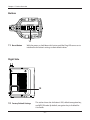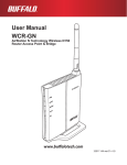
1
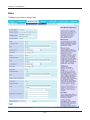
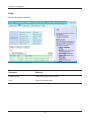
User Manual
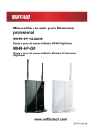
WCR-GN / WCR-HP-GN
AirStation N Technology Wireless N150
Router, Access Point, & Bridge
www.buffalotech.com
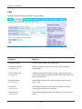
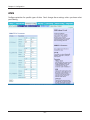
Contents
Chapter 1 - Product Overview.......................................... 5
Features................................................................................... 5
150 Mbps High Speed Mode.................................................... 6
Package Contents.................................................................... 6
WCR-GN Hardware Overview................................................. 7
Front Panel LED’s........................................................................... 7
Back Panel...................................................................................... 9
Bottom............................................................................................. 10
Right Side....................................................................................... 10
WCR-HP-GN Hardware Overview........................................... 11
Front Panel LED’s........................................................................... 11
Back Panel...................................................................................... 13
Bottom............................................................................................. 14
Right Side....................................................................................... 14
Chapter 2 - Placing Your AirStation................................. 15
Antenna Placement.................................................................. 15
Vertical Placement................................................................... 15
Horizontal Placement............................................................... 16
Chapter 3 - Installation......................................................17
Initial Setup.............................................................................. 17
WDS Setup.............................................................................. 19
Chapter 4 - Configuration................................................. 23
Accessing the Web-based Configuration Interface.................. 23
-1-
Configuration Menu (Router Mode).......................................... 25
Configuration Menu (Bridge Mode).......................................... 27
Setup........................................................................................ 29
Internet/LAN (LAN Config)....................................................... 31
Internet (Router Mode only)............................................................ 31
PPPoE (Router Mode only)............................................................. 32
DDNS (Router Mode only).............................................................. 34
LAN................................................................................................. 36
DHCP Lease (Router Mode only)................................................... 38
NAT (Router Mode only)................................................................. 39
Route.............................................................................................. 40
Wireless Config........................................................................ 41
WPS................................................................................................ 41
AOSS.............................................................................................. 42
Basic............................................................................................... 44
Advanced........................................................................................ 48
WMM............................................................................................... 49
MAC Filter....................................................................................... 51
WDS (Bridge Mode only)................................................................ 52
Security (Router Mode only).................................................... 54
Firewall (Router Mode only)............................................................ 54
IP Filter (Router Mode only)............................................................ 56
VPN Pass-Through (Router Mode only)......................................... 57
LAN Config (Router Mode only)............................................... 58
Port Forwarding (Router Mode only)............................................... 58
DMZ (Router Mode only)................................................................ 59
UPnP (Router Mode only)............................................................... 60
QoS (Router Mode only)................................................................. 61
Admin Config............................................................................ 62
Name.............................................................................................. 62
Password........................................................................................ 63
Time/Date....................................................................................... 64
NTP................................................................................................. 65
-2-
Access............................................................................................ 66
Log.................................................................................................. 67
Save/Restore.................................................................................. 68
Initialize/Restart.............................................................................. 69
Update............................................................................................ 70
Diagnostic................................................................................ 71
System Info..................................................................................... 71
Logs................................................................................................ 73
Packet Info...................................................................................... 74
Client Monitor.................................................................................. 75
Ping................................................................................................. 76
Chapter 5 - Connect to a Wireless Network.................... 77
Automatic Secure Setup (AOSS/WPS).................................... 77
Windows 7 or Vista (Client Manager V).......................................... 78
Windows XP (Client Manager 3)..................................................... 79
Mac OS X (AOSS Assistant)........................................................... 80
Other Devices (e.g. Game Console)............................................... 81
Manual Setup........................................................................... 81
Windows 7 (WLAN AutoConfig)...................................................... 81
Windows Vista (WLAN AutoConfig)................................................ 82
Windows XP (Wireless Zero Configuration).................................... 85
Mac OS X (Wi-Fi)............................................................................ 86
Chapter 6 - Troubleshooting............................................. 87
Cannot connect to the Internet over wired connection............. 87
Cannot access the web-based configuration interface............ 87
Cannot connect to the network wirelessly................................ 88
You forgot AirStation's SSID, Encryption Key, or Password..... 88
The link speed is slower than 150 Mbps (Maximum link speed
is only 72Mbps)........................................................................ 88
Other Tips................................................................................. 89
-3-
Appendix A - Specifications............................................. 92
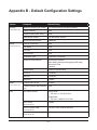
Appendix B - Default Configuration Settings................. 93
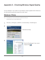
Appendix C - Checking Wireless Signal Quality............ 98
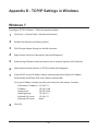
Appendix D - TCP/IP Settings in Windows...................... 101
Appendix E - Restoring the Default Configuration......... 105
Appendix F - Regulatory Compliance Information......... 106
Appendix G - Environmental Information....................... 111
Appendix H - GPL Information......................................... 112
-4-
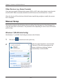
Chapter 1 - Product Overview
Features
Supports IEEE802.11n and IEEE802.11b/g
With support for Wireless-N, Wireless-G, and Wireless-B standards, the AirStation can transfer data to
and from all standard 2.4 GHz wireless clients.
Supports WDS
WDS bridging allows multiple units to operate in a bridged network for extended coverage.
Dual speed mode
Dual speed mode makes wireless transmission faster by using 2 channels, allowing 150 Mbps data
transmission.
Support AOSS and WPS
Both AOSS (AirStation One-touch Secure System) and WPS (Wi-Fi Protected Setup) are supported.
These automatic connection standards make connection with compatible wireless devices easier.
Security Features
The AirStation is equipped with the following security features:
• AOSS
• WPS
• WPA-PSK (TKIP/AES)
• WPA2-PSK(TKIP/AES)
• WPA/WPA2 mixed PSK
• WEP(128/64 bit)
• Privacy Separator
• MAC address access restriction
• Deny Any Connection/SSID stealth
• Web configuration interface with password
• Firewall with easy rules
Automatic Channel Selection
Monitors wireless interference and automatically assigns the clearest, best channel.
Initialization
To restore settings back to the factory defaults, hold down the Reset button on the bottom of the
unit.
-5-
Chapter 1 Product Overview
Browser Based Administration
This unit can be easily configured from a web browser on your computer.
150 Mbps High Speed Mode
150 Mbps is the link speed of AirStation when using Wireless-N mode. It represents actual wireless
data speeds, including overhead. Because the overhead is not available for user data transfer, usable
wireless throughput will be substantially slower.
Package Contents
Following items are included in your AirStation. If any of the items are missing, please contact your
vender.
WCR-GN
• Main unit...............................................................................................1
• Stand......................................................................................................1
• AC adapter............................................................................................1
• LAN cable..............................................................................................1
• AirStation Utility CD..........................................................................1
• Quick Setup Guide............................................................................1
WCR-HP-GN
• Main unit...............................................................................................1
• Detachable antenna.........................................................................1
• Stand......................................................................................................1
• AC adapter............................................................................................1
• LAN cable..............................................................................................1
• AirStation Utility CD..........................................................................1
• Quick Setup Guide............................................................................1
-6-
Chapter 1 Product Overview
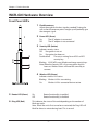
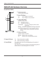
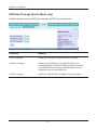
WCR-GN Hardware Overview
Front Panel LED’s
1
Flexible antenna
Adjust the angle for the best signal as needed. Turning the unit so that the antenna points straight up will probably give the strongest signal.
2
Power LED (Green)
On: The AC adapter is connected
Off: The AC adapter is not connected
1
3
3
4
2
5
6
4
5
Router LED (Green)
Security LED (Amber)
Indicates security status.
Off: Encryption is not set
On: Encryption has been set
Double blink:
The unit is waiting for an AOSS or WPS
security key
Blinking: AOSS/WPS error; failed to exchange security keys
Note: When the Security LED is lit, an encryption key has been set. Wireless clients will need the same key to
connect.
Wireless LED (Green)
Indicates wireless LAN status.
Blinking: Wireless LAN is transmitting
On: On: Off:
Wireless LAN is connected but not active
Router functionality is enabled
Router functionality is disabled
6
Diag LED (Red) This indicates the status of the unit depending on the number of blinks per cycle.
Note: When the unit is first turned on or restarted, the Diag LED will blink for almost a minute during boot. This is normal.
-7-
Chapter 1 Product Overview
Diag LED
status
Meaning
Status
2 blinks *1
Flash ROM error
Cannot read or write to the flash memory.
3 blinks *
Ethernet (wired) LAN
error
Ethernet LAN controller is malfunctioning.
4 blinks *1
Wireless LAN error
Wireless LAN controller is malfunctioning.
5 blinks
IP address setting error
Because the network addresses of both the Internet port (INTERNET
port) and the LAN port are the same, it is not possible to establish
communication. Change the LAN side IP address of this unit.
1
Continuously Updating the firmware
blinking *2
Saving settings
Initializing settings
Updating the firmware.
Saving the settings.
Initializing the settings.
*1
Unplug the AC adapter from the wall socket, wait for a few seconds, and then plug it again. If the
light still flashes, please contact technical support.
*2
Never unplug the AC adapter while the Diag LED is blinking continuously.
-8-
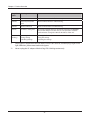
Chapter 1 Product Overview
Back Panel
7
AOSS Button
Hold down this button until the Security LED flashes (about 1 second), while the unit’s power is on, initiates AOSS/WPS mode, allowing the unit to exchange security keys with AOSS or WPS compatible devices.
8
LAN Port
Connect your computer, hub, or other Ethernet devices
to these ports. This switching hub supports 10 Mbps and 100 Mbps connections.
AOSS
LAN
7
1
2
8
9
Internet (WAN) Port
10 Mbps and 100 Mbps connections are supported.
Note: In bridge/AP mode, the Internet port becomes a regular LAN port, for a total of 5 usable LAN ports.
3
10Power Connector
4
INTERNET
9
POWER
Connect the included AC adapter.
10
-9-
Chapter 1 Product Overview
RESET
Bottom
11
11
Reset Button
With the power on, hold down this button until the Diag LED comes on to
initialize the AirStation’s settings to their default values.
Right Side
12
12
Factory Default Settings
This sticker shows the AirStation’s SSID, default encryption key,
and WPS PIN code. By default, encryption key is disabled for
Asia Pacific.
- 10 -
Chapter 1 Product Overview
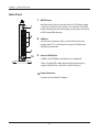
WCR-HP-GN Hardware Overview
Front Panel LED’s
1
Antenna connector
Screw on the antenna here.
2
Power LED (Green)
On: The AC adapter is connected
Off: The AC adapter is not connected
2
3
4
1
3
5
6
Off: Encryption is not set
On: Encryption has been set
Double blink:
The unit is waiting for an AOSS or WPS
security key
Blinking: AOSS/WPS error; failed to exchange security keys
Note: When the Security LED is lit, an encryption key has been set. Wireless clients will need the same key to
connect.
4
5
Router LED (Green)
On: Off:
Security LED (Amber)
Indicates security status.
Wireless LED (Green)
Indicates wireless LAN status.
Blinking: Wireless LAN is transmitting
On: Wireless LAN is connected but not active
Router functionality is enabled
Router functionality is disabled
6
Diag LED (Red) This indicates the status of the unit depending on the number of blinks per cycle.
Note: When the unit is first turned on or restarted, the Diag LED will blink for almost a minute during boot. This is normal.
- 11 -
Chapter 1 Product Overview
Diag LED
status
Meaning
Status
2 blinks *1
Flash ROM error
Cannot read or write to the flash memory.
3 blinks *
Ethernet (wired) LAN
error
Ethernet LAN controller is malfunctioning.
4 blinks *1
Wireless LAN error
Wireless LAN controller is malfunctioning.
5 blinks
IP address setting error
Because the network addresses of both the Internet port (INTERNET
port) and the LAN port are the same, it is not possible to establish
communication. Change the LAN side IP address of this unit.
1
Continuously Updating the firmware
blinking *2
Saving settings
Initializing settings
Updating the firmware.
Saving the settings.
Initializing the settings.
*1
Unplug the AC adapter from the wall socket, wait for a few seconds, and then plug it again. If the
light still flashes, please contact technical support.
*2
Never unplug the AC adapter while the Diag LED is blinking continuously.
- 12 -
Chapter 1 Product Overview
Back Panel
AOSS
LAN
7
1
2
8
3
4
7
AOSS Button
Hold down this button until the Security LED flashes (about 3 seconds), while the unit’s power is on, initiates AOSS/WPS mode, allowing the unit to exchange security keys with AOSS or WPS compatible devices.
8
LAN Port
Connect your computer, hub, or other Ethernet devices
to these ports. This switching hub supports 10 Mbps and 100 Mbps connections.
INTERNET
9
POWER
10
9
Internet (WAN) Port
10 Mbps and 100 Mbps connections are supported.
Note: In bridge/AP mode, the Internet port becomes a regular LAN port, for a total of 5 usable LAN ports.
10Power Connector
Connect the included AC adapter.
- 13 -
Chapter 1 Product Overview
RESET
Bottom
11
11
Reset Button
With the power on, hold down this button until the Diag LED comes on to
initialize the AirStation’s settings to their default values.
Right Side
12
12
Factory Default Settings
This sticker shows the AirStation’s SSID, default encryption key,
and WPS PIN code. By default, encryption key is disabled for
Asia Pacific.
- 14 -
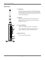
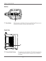
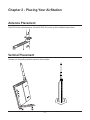
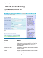
Chapter 2 - Placing Your AirStation
Antenna Placement
The WCR-GN has a fixed antenna. For the WCR-HP-GN, screw on the included antenna here.
Vertical Placement
To place unit vertically, attach the stand as shown below.
2
1
1
- 15 -
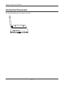
Chapter 2 Placing Your AirStation
Horizontal Placement
For horizontal placement, the stand is not used.
- 16 -
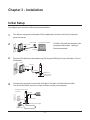
Chapter 3 - Installation
Initial Setup
To configure your AirStation, follow the procedure below.
1
Turn off your computer and modem. If the modem doesn’t have an off switch, unplug its
power connector.
2
1) turn off the computer
2) disconnect
2) disconnect
ÏÆÆ
computer
modem
3
Find the LAN cable that connects your
computer and modem. Unplug it
from the computer.
Plug the LAN cable from the modem into the Internet (WAN) port of your AirStation. Turn on
the modem.
modem
LAN cable
ÌÁÎ
ᴮ
1) connect
ᴯ
ᴰ
2) connect
ᴱ
ÉÎÔÅÒÎÅÔ
INTERNET port
ÐÏ×ÅÒ
AirStation wireless
router (rear side)
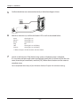
4
Connect your computer to one of the AirStation’s LAN ports with the Ethernet cable.
Turn on the AirStation, wait one minute, and then turn on your computer.
AirStation wireless router
(rear side)
1) connect
PC
ÌÁÎ
ᴮ
ᴯ
ᴰ
1) connect
ᴱ
ÉÎÔÅÒÎÅÔ
Ethernet cable
ÐÏ×ÅÒ
2) connect the power supply
power outlet
- 17 -
Chapter 3 Installation
5
Confirm the devices are connected correctly as the below diagram shows.
computer
ADSS
LAN
ON
1
2
3
4
INTERN
ET
modem
POWE
R
power outlet
6
Wait for a minute or so, until the AirStation’s LEDs are lit as described below:
Power
Wireless
Router
Diag
LAN
Internet
Green light is on
Green light is on
Green light is on
Off
Green light is on or blinking
Green light is on or blinking
※Refer to chapter 1 for LED locations and other details.
7
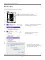
Launch a web browser. If the [home] setup screen is displayed, setup is complete.
If a user name and password screen are displayed, enter [root] (in lower case) for the user
name, leave the password blank, and click [OK]. Follow the instructions on the screen to
complete setup.
You’ve completed initial setup of your AirStation. Refer to Chapter 4 for advanced settings.
- 18 -
Chapter 3 Installation
WDS Setup
To configure the WDS, follow the procedure below.
ER
POW
TY
URI
SEC
ESS
REL
WEI
TER
ROU
DIA
Internet
modem
G
Extend the
wireless coverage
wireless AP
computer
computer
wireless connection
blocked
AirStation
(WDS enabled©
computer
1
Change your computer’s IP to a fixed address. For details, please refer to Appendix D (page 101).
ex) IP address
Subnet mask
Default gateway
Preferred DNS server
Alternate DNS server
2
192.168.11.80
255.255.255.0
blank
blank
blank
Turn off your computer.
- 19 -
Chapter 3 Installation
3
Connect your computer to one of the AirStation’s LAN ports with the Ethenet cable.
Turn on the AirStation, wait one minute, and then turn on your computer.
AirStation wireless router
(rear side)
1) connect
PC
ÌÁÎ
ᴮ
ᴯ
ᴰ
1) connect
ᴱ
ÉÎÔÅÒÎÅÔ
Ethernet cable
ÐÏ×ÅÒ
2) connect the power supply
power outlet
4
Wait for about a minute, until the AirStation’s LEDs are lit as described below:
Power
Wireless
Router
Diag
Green light is on
Green light is on
Green light is on
Off
※Refer to chapter 1 for LED locations and other details.
5
Open the web configuration interface (page 23).
6
In the [Mode information] menu, select [Bridge Mode], then click [Apply].
7
When this below screen appears, re-enter
the web configuration interface username
"root" and password. Click [OK].
- 20 -
Chapter 3 Installation
8
The web configuration interface will open. Click [Wireless Config] , then [WDS].
9
Check [Use].
10
Follow the directions below.
AOSS Settings
Select [AOSS] from [Connection type] and click the AOSS button. Also push the AOSS button
on the unit intended to connect. Automatic configuration will take about a minute. To return
the unit to its original IP address settings, refer to Appendix D.
Manual Settings
Select [Manual] from [Connection type]. Then click [Search].
- 21 -
Chapter 3 Installation
11
12
13
A list of available wireless APs will be generated. Select the target AP and click [Select].
Click [Search again] if no APs are found.
Configure the security settings to match that of the target AP, then click [Apply].
Revert your computer's IP adress settings to their original values as secribed in Appendix D
(page 101).
ex) IP address
Subnet mask
obtain an IP address automatically
obtain DNS server address automatically
WDS setup is complete. Refer to Chapter 4 for advanced settings.
- 22 -
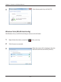
Chapter 4 - Configuration
To access the AirStation’s advanced settings, use the web-based configuration interface.
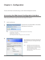
Accessing the Web-based Configuration Interface
Follow the procedure below to open the web-based configuration interface.
1
2
Launch a web browser.
Enter the router’s LAN-side IP address in the address
field, and press the [Enter] key.
Note: ・The AirStation’s default LAN-side IP address depends on its mode setting.
In router mode: 192.168.11.1
In bridge mode: 192.168.11.100
・If you changed the IP address setting, then use the new IP address.
3
Enter [root] (lower case) for the username and
the password that you set during initial setup.
Click [OK].
・By default, the password is blank (not set).
・If you forget your password, hold down the
Reset button (page 10) to initialize all settings.
The password will then be blank.
Note that all other settings will also revert to
their default values.
Note:
- 23 -
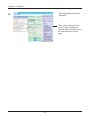
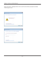
Chapter 4 Configuration
4
The configuration interface is
displayed.
Help is always displayed on the
right side of the configuration
interface. Refer to the Help screens
for more information on each
page.
- 24 -
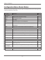
Chapter 4 Configuration
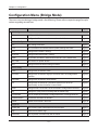
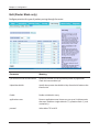
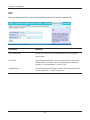
Configuration Menu (Router Mode)
The menu structure for the AirStation in router mode is the following. Please refer to the pages listed
at right for explanations of each item.
Main screen
Descriptions
Page
Internet
Configure Internet side port and settings
Page 31
PPPoE
PPPoE settings (DSL login)
Page 32
DDNS
DNS settings
Page 34
LAN
LAN side port and DHCP server configuration
Page 36
DHCP Lease
DHCP lease settings
Page 38
NAT
Network address translation settings, used to connect LAN side devices
to the Internet
Page 39
Route
Configure the IP communication route that the AirStation uses
Page 40
WPS
WPS settings and status
Page 41
AOSS
AOSS (AirStation One-touch Secure System) settings and status
Page 42
Basic
Configure basic wireless settings
Page 44
Advanced
Configure advanced wireless settings
Page 48
WMM
Set priorities for Wireless Multimedia Extensions (Wi-Fi Multimedia)
Page 49
MAC Filter
Limit access to specific devices
Page 51
Firewall
Protect your computer from outside intruders
Page 54
IP Filter
Edit IP filters which relates to the packets passing through the LAN side Page 56
and the Internet side
VPN
Pass-through
Configure IPv6 passthrough, PPPoE passthrough, and PPTP passthrough
Internet/LAN
Wireless Config
Security
Page 57
LAN Config
Port Forwarding
Configure port translation and exceptions for games and other programs Page 58
- 25 -
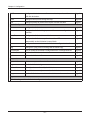
Chapter 4 Configuration
DMZ
Configure a destination to transfer communication packets without a
LAN side destination.
Page 59
UPnP
Configure UPnP (Universal Plug and Play)
Page 60
QoS
Configure priority for packets that require a certain data flow
Page 61
Name
Configure the AirStation’s name
Page 62
Password
Configure the AirStation’s login password for access to configuration
interfaces
Page 63
Time/Date
Configure the AirStation’s internal clock
Page 64
NTP
Configure the AirStation to synchronize with an NTP server to
automatically set the AirStation’s internal clock
Page 65
Access
Configure access restrictions to the AirStation’s configuration interfaces
Page 66
Log
Configure a syslog server to manage the AirStation’s logs
Page 67
Save/Restore
Save or restore the AirStation’s configuration from a configuration file
Page 68
Initialize/Restart
Initialize the AirStation or reboot it
Page 69
Update
Update the AirStation’s firmware
Page 70
System Info
View current system information for the AirStation
Page 71
Logs
Check the AirStation’s logs
Page 73
Packet Info
View all packets transferred by the AirStation
Page 74
Client Monitor
View all devices currently connected to the AirStation
Page 75
Ping
Test the AirStation’s connection to other devices on the network
Page 76
Admin Config
Diagnostic
Logout
Click this to log out of the AirStation’s configuration interfaces
- 26 -
Chapter 4 Configuration
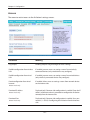
Configuration Menu (Bridge Mode)
The menu structure during a bridge mode is the following. Please refer to respective page for explanations regarding to each item.
Main screen
Descriptions
Page
LAN
Configure LAN side ports and devices
Page 36
Route
Configure the IP communication route that the AirStation uses
Page 40
WPS
WPS settings and status
Page 41
AOSS
AOSS (AirStation One-touch Secure System) settings and status
Page 42
Basic
Configure basic wireless settings
Page 44
Advanced
Configure advanced wireless settings
Page 48
WMM
Set priorities for Wireless Multimedia Extensions (Wi-Fi Multimedia)
Page 49
MAC Filter
Limit access to specific devices
Page 51
WDS
Configure communication among AirStation
Page 52
Name
Configure the AirStation’s name
Page 62
Password
Configure the AirStation’s login password for access to configuration
interfaces
Page 63
Time/Date
Configure the AirStation’s internal clock
Page 64
NTP
Configure the AirStation to synchronize with an NTP server to
automatically set the AirStation’s internal clock
Page 65
Access
Configure access restrictions to the AirStation’s configuration interfaces
Page 66
Log
Configure a syslog server to manage the AirStation’s logs
Page 67
Save/Restore
Save or restore the AirStation’s configuration from a configuration file
Page 68
Initialize/Restart
Initialize the AirStation or reboot it
Page 69
Update
Update the AirStation’s firmware
Page 70
System Info
View current system information for the AirStation
Page 71
Logs
Check the AirStation’s logs
Page 73
Packet Info
View all packets transferred by the AirStation
Page 74
LAN Config
Wireless Config
Admin Config
Diagnostic
- 27 -
Chapter 4 Configuration
Client Monitor
View all devices currently connected to the AirStation
Page 75
Ping
Test the AirStation’s connection to other devices on the network
Page 76
Logout
Click this to log out of the AirStation’s configuration interfaces
- 28 -
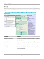
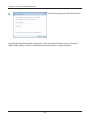
Chapter 4 Configuration
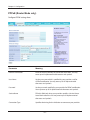
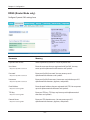
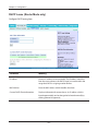
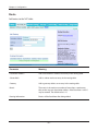
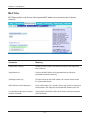
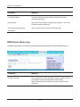
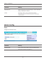
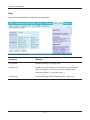
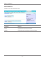
Setup
The home page of the configuration interface. You can verify settings and the status of the AirStation
here.
Parameter
Meaning
Internet/LAN (LAN Config)
Click this tab to display the configuration interface for the Internet
port and LAN ports.
Wireless Config
Click this tab to display the configuration ���������������������������
interface������������������
for wireless settings.
Security
Click this tab to display the configuration interface for security.
LAN Config
Click this tab to display the configuration interface to open ports for
games and applications.
- 29 -
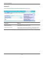
Chapter 4 Configuration
Parameter
Meaning
Admin Config
Click this tab to display the configuration interface which is related
to the administration of the AirStation.
Diagnostic
Click this tab to display the status of the AirStation.
Easy Setup
Enable you to configure the AirStation easily such as an encryption
method of the wireless signal or changing a wireless channel.
Mode Information
Switches router mode and bridge mode.
Internet Information
Displays the current information where the AirStation is connected
on the Internet side.
Router mode only
Check Connection
Router mode only
Clicking this button to check if the AirStation is connected to the
Internet properly.
Refresh
Clicking this button to refresh the current screen.
Router mode only
Wireless
Displays the current wireless settings.
AOSS
Click this button to display the AOSS configuration interface.
WPS
Click this button to display the WPS configuration interface.
Language
Enable you to select the language you use.
If Auto is selected, the same language displayed on the browser will
be selected automatically.
Logout
Log out from the configuration interface of the AirStation. If the
web configuration interface is not used for 5 minutes, it will log out
automatically.
- 30 -
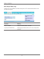
Chapter 4 Configuration
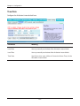
Internet/LAN (LAN Config)
Internet (Router Mode only)
Configure the Internet (WAN) port here.
Parameter
Meaning
Method of Acquiring IP Address
Specify how the Internet side IP address is obtained.
Default Gateway
Configure an IP address for the default gateway.
Address of DNS Name Server
Specify an IP address of the DNS server.
Internet MAC Address
Configure the Internet side MAC address.
Note: Configuring an improper MAC address may make the AirStation
unusable. Be careful!
MTU size of Internet Port
The Internet (WAN) port’s MTU size may be set to any value from
578 to 1500 bytes.
- 31 -
Chapter 4 Configuration
PPPoE (Router Mode only)
Configure PPPoE settings here.
Parameter
Meaning
Name of Connection
Enter the name to identify the connected destination. You may
enter up to 32 alphanumerical characters and symbols.
User Name
Set the user name which is specified by your provider, used for
a PPPoE certification. You may enter up to 32 alphanumerical
characters and symbols.
Password
Set the password specified by your provider for PPPoE certification.
You may enter up to 32 alphanumerical characters and symbols.
Service Name
Fill in this field only when your provider specifies a Service Name.
Leave blank otherwise. You may enter up to 32 alphanumerical
characters and symbols.
Connection Type
Specifies the timing for the AirStation to connect to your provider.
- 32 -
Chapter 4 Configuration
Parameter
Meaning
Automatic disconnection
Sets the timer for disconnection if the connection method is set
to [Connect on Demand] or [Manual]. You can enter up to 1440
minutes.
Authorization
Configure an authorization method with a provider.
MTU Size
The PPPoE MTU size may be set to any value from 578 to 1492.
MRU size
The PPPoE MRU (Maximum Receive Unit) size may be set to any
value from 578 to 1492.
Keep Alive
If enabled, the AirStation will request an LCP echo from the PPP
server once a minute. If the connection server doesn't respond
within 6 minutes, the Internet connection will be cut off. If the PPP
connection is often cut off, disable this.
- 33 -
Chapter 4 Configuration
DDNS (Router Mode only)
Configure Dynamic DNS settings here.
Parameter
Meaning
Dynamic DNS Service
Select a provider (DynDNS or TZO) for Dynamic DNS.
User Name
Enter the username that you registered with DynDNS. You may
enter up to 64 alphanumerical characters and symbols.
Only when DynDNS is selected
Password
Only when DynDNS is selected
Hostname
Only when DynDNS is selected
Email Address
Only when selecting TZO
TZO Key
Only when selecting TZO
Domain Name
Only when selecting TZO
Enter your DynDNS password. You may enter up to 64
alphanumerical characters and symbols.
Enter your DynDNS hostname. Hostnames may include up to 255
alphanumerical characters, hyphens, and periods.
Enter the email address that you registered with TZO. You may enter
up to 64 alphanumerical characters and symbols.
Enter your TZO key. TZO keys may have up to 64 alphanumerical
characters and symbols.
Enter your TZO domain name. You may enter up to 255
alphanumerical characters, hyphens, and periods.
- 34 -
Chapter 4 Configuration
Parameter
Meaning
IP Address Update Period
Specifies the period to notify the dynamic DNS service provider of
the current IP address. When DynDNS is selected, set it between 0
and 35 days. When TZO is selected, set it between 0 and 99 days. If
0 (zero) is set, no periodic update is performed.
Internet Side IP Address
The WAN-side IP address of the AirStation’s Internet port. This
address is sent to the dynamic DNS service provider.
Domain Name
The domain name assigned by the dynamic DNS Service provider.
The AirStation can be accessed from the Internet using this domain
name.
Status
Displays the current status of the dynamic DNS service.
- 35 -
Chapter 4 Configuration
LAN
Configure the LAN side port and DHCP server settings.
Parameter
Meaning
LAN Side IP Address
Set a LAN side IP address and subnet mask.
DHCP Server Function
Enable or disable the DHCP server, which assigns IP addresses
automatically.
Router Mode only
DHCP IP Address Pool
Router Mode only
Advanced Settings
Router Mode only
Lease Period
Router Mode only
Default Gateway
Router Mode only
Configure the range of IP addresses to be assigned by the DHCP
server and IP addresses to be excluded from that range. Values from
0-253 may be entered.
Select Display to display the advanced settings options for the
DHCP server.
Set the effective period of an IP address assigned by the DHCP
server. Up to 999 hours may be entered.
Set the default gateway IP address for the DHCP server to issue to
clients.
- 36 -
Chapter 4 Configuration
Parameter
Meaning
DNS Servers
Set the DNS server IP address for the DHCP server to issue to clients.
Router Mode only
WINS Server
Router Mode only
Domain Name
Set the WINS server IP address for the DHCP server to issue to
clients.
Router Mode only
Set the domain name for the DHCP server to issue to clients. You
may enter up to 127 alphanumerical characters, hyphens, and
periods.
Default Gateway
Set the default gateway IP address.
Bridge Mode only
DNS Server Address
Set the DNS server IP address.
Bridge Mode only
- 37 -
Chapter 4 Configuration
DHCP Lease (Router Mode only)
Configure DHCP leasing here.
Parameter
Meaning
IP Address
Enter an IP address to lease manually. The IP address should be
from the same subnet as the DHCP scope, but not be within the
range that DHCP is assigning to other devices.
MAC Address
Enter the MAC address which identifies the client.
Current DHCP Client Information
Displays information for current leases. An IP address which is
leased automatically can be changed to be leased manually by
clicking [Manual Assignment].
- 38 -
Chapter 4 Configuration
NAT (Router Mode only)
Configure NAT (network address translation) settings here. NAT is used to connect devices on the
LAN side to the Internet.
Parameter
Meaning
Address Translation
Enable to use Network Address Translation.
Log Output of Deleted Packets
Enable logging for deleted packets (such as errors) during address
translation.
- 39 -
Chapter 4 Configuration
Route
Add routes to the NAT table.
Parameter
Meaning
Destination Address
Adds a destination IP address to an entry in the routing table.
Subnet Mask
Adds a subnet mask to an entry in the routing table.
Gateway
Adds a gateway address to an entry in the routing table.
Metric
The metric is the maximum number of router hops a packet may
take on the way to its destination address. Values between 1 and 15
may be entered. The default value is 15.
Routing Information
Entries will be listed here after being added.
- 40 -
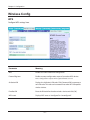
Chapter 4 Configuration
Wireless Config
WPS
Configure WPS settings here.
Parameter
Meaning
WPS
Enable to use WPS automatic configuration.
External Registrar
Enable to accept configuration requests from other WPS devices.
Note: Configuration requests will be ignored if AOSS is in use.
AirStation PIN
Displays the AirStation’s PIN code. Click [Generate PIN] to generate a
new PIN code. This code can be entered into other WPS-compatible
wireless devices.
Enrollee PIN
Enter the PIN code for the other wireless device and click [OK].
WPS status
Displays WPS status as “configured” or “unconfigured”.
- 41 -
Chapter 4 Configuration
AOSS
Configure AOSS settings here.
Parameter
Meaning
Initiates AOSS automatic wireless configuration. Click this, then
press or click the AOSS button on your AOSS-compatible wireless
client. Repeat for additional AOSS clients.
Click this button to disconnect AOSS connections.
Note : If AOSS connections are disconnected, the SSID and encryption
keys will be restored to their most recent settings before using
AOSS.
- 42 -
Chapter 4 Configuration
Parameter
Meaning
Exclusive SSID for WEP
You may allow a separate SSID for WEP connections. If this is
disabled, clients will not be able to connect with WEP.
Encryption level expansion
Adds additional encryption options including WPA/WPA2-PSKmixed mode.
Dedicated WEP SSID isolation
Set a separate SSID and network segment specifically for WEP
connections. Devices connected with WEP will not be able
to communicate with devices connected using AES/TKIP. All
connected devices will be able to communicate with the internet.
AOSS Button on the AirStation Unit
If enabled, AOSS will be initiated when the physical AOSS button is
pressed. Disable to prevent the button from initiating AOSS.
Current Encryption Information
Displays the type of encryption, SSID, and encryption key that AOSS
has configured.
AOSS Connection only
[Random]
Click to enter random values for SSID, encryption key, and other
settings.
[KEY base]
Click to return the SSID, encryption key, and other wireless settings
to the values on the case sticker.
enable for EU/US only
[Reset]
Click to return the SSID, encryption key, and other wireless settings
to their previous values.
AOSS Client Information
Displays status of connected AOSS clients.
AOSS Connection only
- 43 -
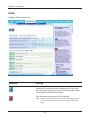
Chapter 4 Configuration
Basic
Configure basic wireless settings here.
- 44 -
Chapter 4 Configuration
Parameter
Meaning
Wireless Radio
Enable to allow wireless communication. If this is unchecked, then
no wireless connections will be allowed.
Wireless Channel
Sets a channel (a range of frequencies) used for wireless
connections. Available range of channels is 1-11.
With Auto Channel selected, the AirStation will automatically use
the best available channel.
This parameter is disabled if WDS is in use.
150Mbps Mode
150 Mbps mode uses twice the normal frequency range, 40
MHz instead of 20 MHz. In uncongested areas this can increase
performance. To use 150 Mbps mode, set the Bandwidth to 40 MHz
and choose an Extension Channel.
Note: If using Auto Channel for the wireless channel, then the Extension
Channel is set automatically.
This parameter is disabled if WDS is in use.
Broadcast SSID
If [Allow] is checked, then the AirStation will respond to SSID
searches from wireless devices by broadcasting its SSID. If [Allow] is
unchecked, then the AirStation ignore SSID searches from wireless
devices.
SSID1
Always enabled and supports all wireless encryption types.
Encryption can be disabled.
SSID2
Always enabled and supports all wireless encryption types.
Encryption can be disabled.
SSID3
SSID3 can use WPA-PSK-AES encryption.
SSID4
SSID4 can use WEP encryption.
Separation
When enabled, wireless devices connected to the AirStation can
communicate only with the Internet, not with each other.
This parameter does not function if WDS is enabled.
SSID
Set SSID using 1-32 alphanumeric character(s).
Authentication
Specify the type of wireless authentication.
- 45 -
Chapter 4 Configuration
Parameter
Meaning
Encryption
Select a type of data encryption for wireless communication from
the following options:
No encryption
Data is transmitted without encryption. Avoid this option since
any communication may be intercepted.
[No encryption] can be selected only when [No authentication] is
selected for Wireless authentication.
WEP
WEP is a common encryption method supported by most devices.
Use an encryption key to communicate with a wireless device.
WEP can only be selected when [No authentication] is selected for
Wireless authentication.
TKIP
TKIP is an encryption method which is more secure than WEP, but
slower. Use an pre-shared-key to communicate with a wireless
device.
TKIP can be selected only when WPA-PSK or WPA2-PSK is selected
for Wireless authentication.
AES
AES is more secure than TKIP, and faster. Use a pre-shared-key to
communicate with a wireless device.
AES can be selected only when WPA-PSK or WPA2-PSK is selected
for Wireless authentication.
TKIP/AES mixed mode
TKIP/AES mixed mode allows both TKIP and AES authentication
and communication.
TKIP/AES mixed mode can be selected only when WPA/WPA2
mixed mode - PSK is selected for Wireless authentication.
WPA-PSK (Pre-Shared Key)
Enter a pre-shared key for use with wireless authentication.
Keys may be character or hexadecimal. For a character key, use 8 to 63
alphanumeric characters (case-sensitive). For a hexadecimal key, enter
64 digits using 0 to 9 and a to f (not case-sensitive).
Setup WEP encryption key
Enter an encryption key to encrypt wireless data.
Keys may be character or hexadecimal. For a character key, use 5 or 13
alphanumeric characters (case-sensitive). For a hexadecimal key, enter
10 or 26 digits using 0 to 9 and a to f (not case-sensitive).
- 46 -
Chapter 4 Configuration
Parameter
Meaning
Rekey interval
Choose an interval from 0 to 1440 minutes for keys to be updated.
- 47 -
Chapter 4 Configuration
Advanced
Configure advanced wireless settings on this page. Don’t change these settings unless you know
what you’re doing.
Parameter
Meaning
Multicast Rate
Sets the communication speed of multi-cast packets.
DTIM Period
Set the beacon responding interval (1 -255). This setting is effective
only when power management is enabled.
Privacy Separator
If enabled, the Privacy Separator blocks communication between
wireless devices connected to the AirStation. Wireless devices will
be able to connect to the Internet but not with each other. Devices
that are connected to the AirStation with wired connections will
still be able to connect to wireless devices normally.
- 48 -
Chapter 4 Configuration
WMM
Configure priorities for specific types of data. Don’t change these settings unless you know what
you’re doing.
- 49 -
Chapter 4 Configuration
Parameter
Meaning
WMM-EDCA Parameters
You don't usually need to change these settings. Using the default
settings is recommended.
Priority
The following priorities may be applied to individual transmission
packets: (Highest) 8, (High) 4, (Normal) 2, and (Low) 1. From the
queue, these packets are processed in order of priority.
CWmin, CWmax
The maximum and minimum value of the contention window.
The contention window is used in the frame collision avoidance
structure performed in IEEE802.11, and generally the smaller the
value in the window, the higher the probability that the queue
obtains the right to send.
AIFSN
The interval to send frames. The unit of the AIFSN is a slot, just as
the window defined by CWmin and CWmax is. The smaller the
interval of sending frames, the faster the algorithm can restart. As
a result, the priority of the queue is higher.
TXOP Limit
The period of time that the queue can use after obtaining the
right to send. The unit is 32 ms. The longer this time, the more
frames can be sent per right to send. However, the queue may
interfere with other packet transmissions. If TXOP Limit is set to 0
(zero), only one frame can be sent per right to send.
- 50 -
Chapter 4 Configuration
MAC Filter
MAC filtering allows only devices with registered MAC addresses to connect to the AirStation
wirelessly.
Parameter
Meaning
Enforce MAC Filtering
Enable to restrict wireless connections to devices with registered
MAC addresses.
Registration List
Displays the MAC addresses of registered devices which are
permitted to connect wirelessly.
[Edit Registration List]
Click this button to add a MAC address of a wireless device to the
list of permitted devices.
MAC Addresses to be Registered
Enter a MAC address of a wireless device you permit to connect to
the AirStation. Click [Register] to add that MAC address to the list.
List of all clients that are associated
with this AirStation
Display the list of all MAC addresses of wireless devices connected
to the AirStation.
- 51 -
Chapter 4 Configuration
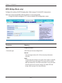
WDS (Bridge Mode only)
Configure the settings for WDS bridging here. Refer to page 19 for the WDS setup process.
Note: You cannot specify WDS while the device is in the router mode.
Change the mode to bridge on TOP screen to display WDS configuration screen.
Parameter
Meaning
WDS
Enable to use WDS.
Connection type
Select how you want to configure WDS.
Manual
Enter the target wireless AP's SSID and security information
manually.
AOSS
Connect with the AirStation using AOSS. If this option is selected,
a special AOSS button will appear. This button can be used for
WDS connection only. Once AOSS connection is set up, the WCRGN will have the same security setting as the other AP in the
bridge. Refer to page 19 for setup directions.
- 52 -
Chapter 4 Configuration
Parameter
Meaning
Connection Status
Displays WDS connection status.
SSID
Enter the target Airstation's SSID.
[ Search ]
Click this button to search for target AirStations by SSID.
Authentication
Enter the target AirStation's wireless authentication method.
Encryption
Enter the target AirStation's encryption type.
WPA-PSK (Pre-shared key)
Enter the target AP's Encryption key (if used).
WEP encryption key setting
Enter the target AP's WEP key (if used).
- 53 -
Chapter 4 Configuration
Security (Router Mode only)
Firewall (Router Mode only)
Configure the AirStation’s firewall here.
Parameter
Meaning
Log Output
Enable to output a log of firewall activity.
Basic Rules
Enable to use any of the quick filters. Preconfigured quick filters
include:
Prohibit NBT and Microsoft-DS Routing
When this is enabled, Microsoft file and printer sharing is blocked
between the WAN and LAN sides of the router. You can configure
this with PPPoE if you select [Use PPPoE Client] or [Use IP
Unnumbered] in Method of Acquiring IP address (on page 31), or if
Easy Setup identified a PPPoE connection during setup.
- 54 -
Chapter 4 Configuration
Parameter
Meaning
Reject IDENT Requests
Enabling this option will answer IDENT requests from the Internet
side with corresponding rejection packets. Enable this option if
you experienced slower transfer speed for network application
such as sending mail, using ftp or displaying on browser. If
you have configured transfer of IDENT requests to the LAN
side computer in the address translation settings (DMZ or TCP
port:113), that setting has higher priority, and overrides this
setting.
Block Ping from Internet
If this is enabled, the AirStation will not respond to pings from the
Internet side. You can configure this with PPPoE if you select [Use
PPPoE Client] in Method of Acquiring IP address (page 31), or if Easy
Setup identified a PPPoE connection during setup.
- 55 -
Chapter 4 Configuration
IP Filter (Router Mode only)
Edit IP filters here.
Parameter
Meaning
Log Output
If enabled, IP filter activity is saved to a log.
Operation
Specify how to process target packets.
Direction
Specify the transmission direction of target packets.
IP Address
Specify the sender's IP address and receiver's IP address of the
target packets.
Protocol
Select a protocol for target transmission packet.
IP Filter Information
Display the list of IP filters which have been registered.
- 56 -
Chapter 4 Configuration
VPN Pass-Through (Router Mode only)
Configure IPv6 pass-through, PPPoE pass-through, and PPTP pass-through here.
Parameter
Meaning
IPv6 Pass-through
Enable to use IPv6 pass-through for address translation.
PPPoE Pass-through
Enable to use PPPoE bridge. Using PPPoE bridge lets you
automatically obtain LAN-side IP addresses from your provider
using the PPPoE protocol because all PPPoE packets can pass
through from the LAN to the WAN side.
PPTP Pass-through
Enable to use the PPTP pass-through for address translation.
- 57 -
Chapter 4 Configuration
LAN Config (Router Mode only)
Port Forwarding (Router Mode only)
Configure port translation here.
Parameter
Meaning
Group
Specify a group name for a new rule to belong to. Select [New
Group] and enter the new group name in the Group Name field
to create a new group. A group name can include up to 16
alphanumeric letters.
Internet Side IP Address
Enter the Internet side IP address (before translation) for the port
translation table entry.
Protocol
Select the Internet side protocol (before translation) for the port
translation table entry.
- 58 -
Chapter 4 Configuration
Parameter
Meaning
LAN Side IP Address
Enter the LAN side IP address (after translation) for the port
translation table entry.
LAN Side Port
Select the LAN side (after translation) port number (1 - 65535) for
the port translation table entry.
Port Forwarding Registration
Information
Shows current entries in the port translation table.
DMZ (Router Mode only)
Configure a destination to transfer communication packets without a LAN side destination to.
Parameter
Meaning
IP Address of DMZ
Enter the IP address of the destination to which packets which are
not routed by a port translation table are forwarded.
Note: RIP protocol packets (UDP port number 520) will not be
forwarded.
- 59 -
Chapter 4 Configuration
UPnP (Router Mode only)
Enable UPnP (Universal Plug and Play) here.
Parameter
Meaning
UPnP
Enable or disable Universal Plug and Play (UPnP) functionality.
- 60 -
Chapter 4 Configuration
QoS (Router Mode only)
Configure priorities for types of packets passing through the router.
Parameter
Meaning
QoS for transmission to the Internet
Determine whether or not to prioritize packets by application.
Check this box to enable QoS.
Upload bandwidth
Specify the upstream bandwidth in kbps from the AirStation to the
internet side.
Enable
Enable or disable this entry.
application name
Enter an application name. Names may use up to 32 alphanumeric
characters, double or single tickmarks ("'), quotation marks (“), and
semicolons (;).
protocol
Select either TCP or UDP.
- 61 -
Chapter 4 Configuration
Parameter
Meaning
destination port
Specify a destination port with the value of 1 - 65535. If this field is
empty, a random port is selected.
priority
Select high, medium, or low priority for these packets.
*Packets whose type isn’t on the list are treated as a level between
medium and low.
Admin Config
Name
Configure the AirStation’s name.
Parameter
Meaning
AirStation Name
Enter a name for the AirStation. Names may include up to 64
alphanumeric characters and hyphens (-).
- 62 -
Chapter 4 Configuration
Password
You may change the login password for the configuration interface here.
Parameter
Meaning
Administrator Name
The username for login is fixed as “root”.
Administrator Password
This password is to log in to the AirStation’s configuration interface.
It may contain up to 8 alphanumeric characters and underscores (_).
- 63 -
Chapter 4 Configuration
Time/Date
Configure the AirStation’s internal clock here.
Parameter
Meaning
Local Date
You may manually set the date of the AirStation’s internal clock.
Local Time
You may manually set the time of the AirStation’s internal clock.
Time Zone
Specify the time zone (offset of Greenwich Mean Time) of the
AirStation's internal clock.
- 64 -
Chapter 4 Configuration
NTP
You may configure an NTP server to automatically correct the AirStation’s time settings.
Parameter
Meaning
NTP Functionality
Enable to use an NTP server to automatically set the AirStation's
internal clock.
NTP Server
Enter the name of the NTP server as a host name, host name with
domain name, or IP address. Up to 255 alphanumeric characters,
hyphens (-), and underscores (_) may be used.
Update Interval
How often should the AirStation submit a time request to the NTP
server? Intervals of 1 - 24 hours may be set.
- 65 -
Chapter 4 Configuration
Access
The screen to restrict access to the AirStation’s settings screens.
Parameter
Meaning
Log Output
Enabling outputs a log of changes to access settings.
Prohibit configuration from wireless
LAN
If enabled, prevents access to settings screens from wirelessly
connected devices (only wired devices may configure).
Prohibit configuration from wired
LAN
If enabled, prevents access to settings screens from wired devices
(only wirelessly connected devices may configure).
Permit configuration from wired
Internet
If enabled, allows access to settings screens from network devices
on the Internet side.
Router mode only
Permitted IP address
Router mode only
Permitted Port
Router mode only
Displayed only if Internet side configuration is enabled. Enter the IP
address of the device that is permitted to configure the AirStation
remotely from the Internet side.
Displayed only if Internet side configuration is enabled. Set a port
number (1 - 65535) if configuring the AirStation from the Internet
side.
- 66 -
Chapter 4 Configuration
Log
Logs may be transferred to a syslog server automatically.
Parameter
Meaning
Log Transfer
Enable to send logs to a syslog server.
Syslog Server
Identify the syslog server by host name, host name with domain
name, or IP address. You may enter up to 255 alphanumeric
characters, hyphens (-), and underscores (_).
Transfer Logs
Choose which logs will be transferred to the syslog server.
- 67 -
Chapter 4 Configuration
Save/Restore
AirStation settings may be saved to a configuration file or restored from one.
Parameter
Meaning
Save current settings
Click [Save] to save the current configuration of the AirStation to a
file. If [Encrypt the configuration file with a password] is checked,
then the configuration file will be password protected with the
specified password.
Restore Configuration from Backup Restore the configuration of the AirStation from a saved
File
configuration file by clicking the [Browse] button, navigating to the
configuration file, and then clicking Restore. If the configuration
file was password protected, then put a check next to [To restore
from the file you need the password], enter the password, and click
[Open].
- 68 -
Chapter 4 Configuration
Initialize/Restart
Initialize or restart the AirStation from here.
Parameter
Meaning
Restart
Click [Restart Now] to restart the AirStation.
Initialize
Click [Initialize Now] to initialize and restart the AirStation.
- 69 -
Chapter 4 Configuration
Update
The screen to update the AirStation’s firmware.
Parameter
Meaning
Firmware Version
Displays the current firmware version of the AirStation.
Firmware File Name
Click [Browse] to specify a firmware file and click [Update
Firmware]. This will update the firmware.
- 70 -
Chapter 4 Configuration
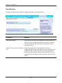
Diagnostic
System Info
System information for the AirStation is displayed here.
- 71 -
Chapter 4 Configuration
Parameter
Meaning
Model
Displays the product name of the AirStation and the firmware
version.
AirStation Name
Displays AirStation Name (as set on page 62).
Operational Mode
Displays the current operational mode of the AirStation.
Internet
Displays WAN port information.
Router mode only
LAN
Displays LAN port information.
Wireless
Displays wireless status.
WDS
Displays the status of WDS.
Bridge mode only
- 72 -
Chapter 4 Configuration
Logs
View the AirStation’s logs here.
Parameter
Meaning
Display log info
Choose the type of logs to display.
Logs
Displays the selected logs.
- 73 -
Chapter 4 Configuration
Packet Info
This screen shows the packets that the AirStation has transferred.
Parameter
Meaning
Sent
Displays the number of packets sent to the WAN (Internet), the
Ethernet LAN, and the wireless LAN.
Received
Displays the number of packets received from the WAN (the
Internet), the Ethernet LAN, and the wireless LAN.
- 74 -
Chapter 4 Configuration
Client Monitor
This screen shows devices that are connected to the AirStation.
Parameter
Meaning
Client Monitor
Displays information ( MAC address, lease IP address, host name,
communication method, wireless authentication and 802.11n) for
devices that are connected to the AirStation.
- 75 -
Chapter 4 Configuration
Ping
A ping test checks whether the AirStation can communicate with a specific network device.
Parameter
Meaning
Destination Address
Enter an IP address or a hostname to ping, and click [Execute]. The
result will be displayed in the [Result] field.
- 76 -
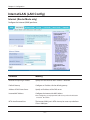
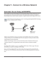
Chapter 5 - Connect to a Wireless Network
Automatic Secure Setup (AOSS/WPS)
AOSS and WPS are systems that enable you to automatically configure wireless LAN settings. Just
pressing the buttons will connect wireless devices and complete security settings. Use them to
automatically connect wireless devices, computers, or game machines which support AOSS or WPS.
AOSS (AirStation One-Touch Secure System) is technology developed by Buffalo Technology.
WPS was created by the Wi-Fi Alliance.
Internet
őŖŔʼn
őŖŔʼn
Modem
AirStation
PC or
Game console
(AOSS Devices)
•Before using AOSS/WPS to connect to a computer with a Buffalo wireless client, install Client
Manager software from the included utility CD on the computer. Consult your wireless client’s
documentation for more information.
•Buffalo’s Client Manager software can be used with the wireless LAN devices built into your
computer. However, it is not guaranteed to work with all wireless LAN devices available.
Note:
To configure WDS with AOSS, you must use a different AOSS button. Refer to page 19 for more
information on using AOSS to configure a WDS bridge.
If you use AOSS to configure WDS, any wireless clients that were previously connected to the
AirStation via AOSS will have been disconnected. Refer to the following procedure to reconnect
them.
- 77 -
Chapter 5 Connect to a Wireless Network
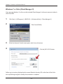
Windows 7 or Vista (Client Manager V)
If you are using Windows 7 or Vista, use the included Client Manager V software to connect wirelessly
with AOSS/WPS.
1
2
3
Click [Start] > [All Programs] > [BUFFALO] > [AirStation Utility] > [Client Manager V].
Click [Create Profile].
If the User Account Control screen opens, click [Yes] or [Continue].
4
Click the [WPS AOSS] button.
Follow any instructions displayed on the screen. When the Security LED on the front of the AirStation stop flashing and glows steadily, the connection is complete.
- 78 -
Chapter 5 Connect to a Wireless Network
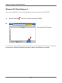
Windows XP (Client Manager 3)
If you are using Windows XP, use Client Manager 3 to connect wirelessly with AOSS/WPS.
1
Right click on the
icon in the system tray and select [Profile].
2
Click the [WPS AOSS] button.
It will take several seconds for your wireless connection to be configured. When the Security LED on
the front of the AirStation stop flashing and glows steadily, the connection is complete.
- 79 -
Chapter 5 Connect to a Wireless Network
Mac OS X (AOSS Assistant)
If you are using Mac OS X 10.7 / 10.6 / 10.5 / 10.4, use the included AOSS Assistant software to connect wirelessly with AOSS.
1
Load the utility CD in your Macintosh.
2
From the menu bar, click [Go] > [Computer].
3
Double-click the CD icon, and then double-click [AOSS Assistant] in the “Mac” folder.
4
The software license screen is displayed. Click [Agree] to proceed.
5
Click [Start AOSS ].
6
Enter the Mac’s username and
password and click [OK].
It will take several seconds for your wireless connection to be configured. When the Security LED on
the front of the AirStation stop flashing and glows steadily, the connection is complete.
- 80 -
Chapter 5 Connect to a Wireless Network
Other Devices (e.g. Game Console)
If you are using a game machine which supports AOSS or WPS, refer to that device’s manual to initiate AOSS/WPS. When instructed, hold down the AOSS button on the AirStation for 1 second.
When the Security LED on the front of the AirStation stop flashing and glows steadily, the connection is complete.
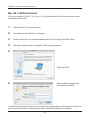
Manual Setup
You can also connect to the AirStation without installing Client Manager V or Client Manager 3 by
using the utility built-in to Windows. The procedure varies depending on which version of Windows
you are using.
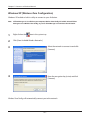
Windows 7 (WLAN AutoConfig)
With Windows 7, use WLAN AutoConfig to connect to the AirStation.
1
Click on the
network icon in the system tray.
2
Select the target AirStation’s name and click
[Connect]. If you will be connecting to this
device in the future, checking [Connect
automatically] is recommended.
- 81 -
Chapter 5 Connect to a Wireless Network
3
Enter the encryption key and click [OK].
Windows Vista (WLAN AutoConfig)
With Windows Vista, use WLAN AutoConfig to connect to the AirStation.
1
Right click on the wireless network icon
2
Click [Connect to a network].
in the system tray.
3
When the screen at left is displayed, select the
network to connect to and click [Connect].
- 82 -
Chapter 5 Connect to a Wireless Network
If the screen below is displayed, click [I want to enter the network key or passphrase instead].
Otherwise,go to step 4.
- 83 -
Chapter 5 Connect to a Wireless Network
4
Enter the encryption key and click [Connect].
Step through the wizard to finish configuration. If the Set Network Location screen is displayed,
select [Home], [Work], or [Public location] depending where you’re using the AirStation.
- 84 -
Chapter 5 Connect to a Wireless Network
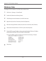
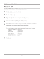
Windows XP (Wireless Zero Configuration)
Windows XP includes a built-in utility to connect to your AirStation.
Note: If Client Manager 3 is installed on your computer, Wireless Zero Config is disabled. Uninstall Client
Manager 3 to use Wireless Zero Config, or just use Client Manager 3 to connect to the AirStation.
1
Right click on the
2
Click [View Available Wireless Networks].
icon in the system tray.
3
Select the network to connect to and click
[Connect].
4
Enter the encryption key (twice) and click
[Connect].
Wireless Zero Config will automatically connect you to the network.
- 85 -
Chapter 5 Connect to a Wireless Network
Mac OS X (Wi-Fi)
Use Wi-Fi on a Mac to connect to the AirStation.
1
Refer to the label on the side of the AirStation.
Make a note of the SSID and KEY printed on the label.
2
Click the
icon in the top section of the
screen and select [Turn Wi-Fi On].
3
Find the SSID from step 1 on the list.
Click it to highlight it.
4
Enter the KEY from step 1 into the
Password entry box, check [Remember
this network], and click [Join].
It will take several seconds for configuration to complete.
- 86 -
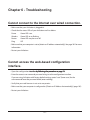
Chapter 6 - Troubleshooting
Cannot connect to the Internet over wired connection.
• Make sure that your AirStation is plugged in!
• Check that the status LEDs of your AirStation are lit as below:
Power
Wireless
Router
Diag
Green LED is on.
Green LED on or flashing
Green LED may be on or off
Off
• Make sure that your computer is set to [obtain an IP address automatically]. See page 101 for more
information.
• Restart your AirStation.
Cannot access the web-based configuration
interface.
• Open the configuration interface���������������������������������������
������������������������������������������������
by following the procedure on page 23.
• Enter the correct user name and password to log in to the configuration interface.
If you are using AirStation with factory default settings, enter “root” (lower case) for the
username and leave the password blank (enter nothing).
• Verify that your web browser is not set to use proxies.
• Make sure that your computer is configured to [Obtain an IP Address Automatically]. (page 101)
• Restart your AirStation.
- 87 -
Chapter 6 Trouble Shooting
Cannot connect to the network wirelessly.
•
Configure your wireless device with the same SSID, encryption type, and encryption key as used
by your AirStation.
The factory defaults are:
SSID -
Printed on the label of the AirStation.
Encryption Type -
WPA/WPA2 mixed mode - PSK (Connect with either WPA-PSK TKIP or WPA2-PSK AES).
Encryption Key -
Printed on the label of the AirStation.
Note: Encryption is disabled by default in Asia Pacific.
• Place your AirStation and wireless devices 2 - 10 feet apart.
• Restart your AirStation.
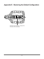
You forgot AirStation's SSID, Encryption Key, or
Password.
Hold down the Reset button (page 105) on your AirStation for 3 seconds to initialize its settings. All
settings, including your password, SSID, and encryption key will be initialized to their defaults.
The followings are the factory default settings of the AirStation.
SSID -
Encryption Type -
Encryption Key -
Printed on the label of the AirStation.
WPA/WPA2 mixed mode - PSK (Connect with either WPA-PSK TKIP or WPA2-PSK AES).
Printed on the label of the AirStation.
(Encryption is disabled by default for Asia Pacific AirStations.)
The link speed is slower than 150 Mbps (Maximum
link speed is only 72Mbps).
By default, the AirStation’s 150 Mbps mode is not enabled. To enable it, use the following procedure:
1. Open the configuration interface of your AirStation (page 23).
2. Click [Wireless SSID & Channel (11n 150Mbps Mode)] in Easy Setup.
3. Change the value in [150 Mbps Mode] - [Band Width] to 40 MHz and click [Apply].
If you still cannot connect at 150 Mbps, check the settings of your wireless client device.
- 88 -
Chapter 6 Trouble Shooting
Other Tips
Issue:
I reset my wireless router to factory settings and forgot how to log in.
Answer:
Open your browser, enter 192.168.11.1 as the browser address, then press the Enter key. You will be
prompted to log in. Enter "root" for the username and leave the password box empty (no password).
Click [OK] to log in. The option to reset your password will be available on the first page.
Issue:
How do I forward ports on my wireless router for my gaming console?
Answer:
Log in to the router. From the home page, go to the Internet Game/ Port Mapping section. Enter the
port that needs to be forwarded and the IP address of the gaming console.
Issue:
How do I enable or modify encryption settings on the wireless router?
Answer:
Log in to the wireless router with your browser. Go to the Wireless Config tab and then select the
Basic tab. Buffalo recommends the use of WPA/WPA2 mixed for wireless encryption. The passphrase/
key should be at least 8 characters in length.
Issue:
How do I change my wireless router's broadcasted network name (SSID)?
Answer:
Log in to the wireless router with your browser. Navigate to Wireless Config - Basic. Find the SSID
setting. Select [Use] and enter the new name for your network. Click [Apply]. Once the wireless
router has rebooted, you will need reconnect any wireless clients to the AirStation using the new
network name. The encryption key will still be the same.
- 89 -
Chapter 6 Trouble Shooting
Issue:
What can I do if my wireless connection drops randomly or seems slow?
Answer:
There are many environmental factors that may affect this behavior. First, ensure the issue is not
range related by locating the wireless router and the device dropping connection in closer proximity
and check whether the connection drops continue.
In some cases, interference from other wireless networks or sources such as 2.4 GHz wireless phones
may impact performance. To work around this scenario, change the wireless channel used by your
wireless router.
Log in to the wireless router with your browser. Click on the Wireless Config tab and then the Basic
tab. The Wireless Channel setting can be selected from channels 1 to 11. If an Auto-Channel option
is available, attempt to use this option to remedy the problem. If Auto-Channel is unavailable,
manually select an alternate channel and click [Apply].
Issue:
Though I am able to successfully make a connection with my wireless router, I am unable to access
the Internet with my web browser.
Answer:
First, power off the Cable or DSL modem, the wireless router, and your computer. Move the router's
mode switch to the on position. Verify that the modem is connected to the wireless router with an
Ethernet cable to the WAN port. Power on the modem and wait one minute. Power on the wireless
router and wait another minute. Power on the computer. Open a browser on the computer and
navigate to a familiar website to verify whether the Internet connection is functioning normally.
If after these steps, an Internet connection is still unavailable, power off the Cable or DSL modem
and computer again and directly connect your computer to the Cable or DSL modem with a cable
between the computer and the port on the modem. Power on the modem and wait one minute.
Power on the computer and again check for an Internet connection.
If an Internet connection IS NOT available with a direct connection to the computer, please call the
Internet Service Provider who installed the modem.
If an Internet connection IS available with a direct connection to the computer, please call our
customer support.
- 90 -
Chapter 6 Trouble Shooting
Issue:
Where can I download the latest drivers, firmware, and instructions for my Buffalo wireless products?
Answer:
The latest drivers and firmware are available online at
www.buffalotech.com
- 91 -
Appendix A - Specifications
Wireless LAN Interface
Standard Compliance
IEEE802.11b / IEEE802.11g / IEEE802.11n technology
Transmission Method
Direct Sequence Spread Spectrum (DSSS), OFDM, SISO
Frequency Range
2,412 - 2,462 MHz (Channels 1 - 11)
Transmission Rate
802.11b/g
54, 48, 36, 24, 18, 12, 9, 6, 11, 5.5, 2, 1 Mbps
802.11n
20 MHz Channel
(LongGI)65,58.5,52,39,26,19.5,13,6.5(1 stream)
(ShortGI)72.2,65.57.8,43.3,28.9,21.7,14.4,7.2(1 steam)
40 MHz Channel
(LongGI)135,121.5,108,61,54,40.5,27,13.5(1 stream)
(ShortGI)150,135,120,90,60,45,30,15(1 stream)
Access Mode
Infrastructure Mode
Security
AOSS, WPA2-PSK (TKIP/AES), WPA/WPA2 mixed PSK, WPA-PSK (TKIP/AES),
128/64 bit WEP, Mac Address Filter
Wired LAN Interface
Standard Compliance
IEEE802.3u (100BASE-TX), IEEE802.3 (10BASE-T)
Transmission Rate
10 / 100 Mbps
Transmission Encoding
100BASE-TX 4B5B/MLT-3, 10BASE-T Manchester Cording
Access Method
CSMA/CD
Speed and Flow Control
10/100, Auto Sensing, Auto MDIX
Number of LAN Ports
4
LAN Port Connector
RJ-45
Other
Power Supply
External AC 100-240V Universal, 50/60 Hz
Power Consumption
WCR-GN
: Approx. 5.8 W (Max)
WCR-HP-GN : Approx. 7.4 W (Max)
Dimensions
WCR-GN
: 118 mm x 104 mm x 23 mm (4.6 x 4.1 x 0.9 in.)
WCR-HP-GN : 130 mm x 105 mm x 23 mm (5.1 x 4.1 x 0.9 in.)
Weight
WCR-GN
: 144 g (5.08 oz.) without stand
WCR-HP-GN : 146 g (5.15 oz.) without stand and antenna
Operating Environment
0 - 40° C (32 - 104° F), 20 - 80% (non-condensing)
- 92 -
Appendix B - Default Configuration Settings
Feature
Parameter
Default Setting
Internet
Method of Acquiring IP Address
Easy Setup (Internet Connection Wizard)
Default Gateway
none
Address of DNS Name Server
none
Internet MAC Address
Use default MAC Address
MTU Size of Internet Port
1500 Bytes
Name of Connection
none
User Name
none
Password
none
Service Name
none
Connection Type
Continuous Connection
Automatic disconnection
Disconnect Condition
When both incoming and outgoing traffic stops
Disconnect Time
5 Minutes
Authorization
Automatic Authorization
MTU Size
1454 Bytes
MRU size
1454 Bytes
Keep Alive
Enabled
Dynamic DNS Service
Disabled
Router Mode only
PPPoE
Router Mode only
DDNS
Router Mode only
LAN
Current Dynamic DNS Informa- none
tion
LAN Side IP Address
Router Mode:
192.168.11.1 (255.255.255.0)
Bridge Mode
192.168.11.100 (255.255.255.0)
DHCP Server
Enabled
Router Mode only
DHCP IP Address Pool
192.168.11.2 for up to 64 addresses
Router Mode only
Lease Period
48 hours
Router Mode only
- 93 -
Appendix B Default Configuration Settings
Feature
Parameter
Default Setting
Default Gateway
AirStation's IP Address
Router Mode only
DNS Servers
AirStation's IP Address
Router Mode only
WINZ Server
Assigned IP address
Router Mode only
Domain Name
Assigned Domain Name
Router Mode only
Default Gateway
none
Bridge Mode only
DNS Server Address
none
Bridge Mode only
DHCP Lease
Router Mode only
Current DHCP Client Informa- none
tion
NAT
Address Translation
Enabled
Log Output of Deleted Packets
Disabled
Route
Routing Information
none
WPS
WPS
Enabled
External Registrar
Enabled
AirStation PIN
An 8-digit random value
(Printed on the label of the AirStation)
WPS Security Information
WPS status:
Router Mode only
- 94 -
configured or unconfigured
Appendix B Default Configuration Settings
Feature
Parameter
Default Setting
AOSS
Encryption Type of Exclusive none
SSID for WEP
Encryption level expansion
function
Enabled
Dedicated WEP SSID isolation
Disabled
AOSS Button on the AirStation Enabled
Unit
Basic
Wireless Radio
Enabled
Wireless Channel
Auto Channel
150Mbps Mode
Band Width: 20MHz
Extension Channel: -
Broadcast SSID
Allow
Separate feature
For US/EU
SSID1: not used
SSID2: used
For AP/RU
SSID1: used
SSID2: not used
SSID
For US/EU
SSID1: not used
SSID2: Configure AirStation’s MAC address + [-1]
SSID3: not used
SSID4: not used
For AP/RU
SSID1: Configure AirStation’s MAC address
SSID2: not used
SSID3: not used
SSID4: not used
Authentication
For US/EU
WPA/WPA2 mixed mode-PSK
For AP/RU
No authentication
Encryption
For US/EU
TKIP/AES mixed mode
For AP/RU
No encryption
Rekey interval
60 minutes
- 95 -
Appendix B Default Configuration Settings
Feature
Parameter
Default Setting
Advanced
Multicast Rate
1Mbps
DTIM Period
1
Privacy Separator
Disabled
WMM
WMM-EDCA Parameters
(Priority AC_BK (Low) )
WMM-EDCA Parameters
(Priority AC_BE (Normal) )
WMM-EDCA Parameters
(Priority AC_VI (High) )
WMM-EDCA Parameters
(Priority AC_VO (Highest) )
MAC Filter
For AP
For STA
CWmin
15
15
CWmax
1023
1023
AIFSN
7
7
TXOP Limit
0
0
For AP
For STA
CWmin
15
15
CWmax
63
1023
AIFSN
3
3
TXOP Limit
0
0
For AP
For STA
CWmin
7
7
CWmax
15
15
AIFSN
1
2
TXOP Limit
94
94
For AP
For STA
CWmin
3
3
CWmax
7
7
AIFSN
1
2
TXOP Limit
47
47
Enforce MAC Filter
Disabled
Registration List
none
WDS
WDS
not used
Firewall
Log Output
Disabled
Basic Rules
Prohibit NBT and Microsoft-DS Routing
Reject IDENT Requests
Block Ping from Internet
Log Output
Disabled
IP Filter Information
none
Router Mode only
IP Filter
Router Mode only
- 96 -
Disabled
Enabled
Enabled
Appendix B Default Configuration Settings
Feature
Parameter
Default Setting
VPN Pass
Through
IPv6 Pass Through
Disabled
PPPoE Pass Through
Disabled
PPTP Pass Through
Disabled
Router Mode only
Port Forwarding
Router Mode only
Port Forwarding Registration none
Information
DMZ
IP Address of DMZ
none
UPnP
Enabled
Router Mode only
UPnP
Router Mode only
QoS
Router Mode only
QoS for transmission to the In- Disabled
ternet
Name
AirStation Name
AP + AirStation's MAC Address
Password
Administrator Name
root (fixed)
Administrator Password
none
Local Date
2010 Year 1 Month 1 Day
Local Time
0 Hour 0 Minute 0 Seconds
Time Zone
(GMT−00:00) Greenwich Mean Time, London
NTP Functionality
Enabled
NTP Server
time, nist, gov
Update Interval
24 hours
Log Output
Disabled
Limitation Item
Prohibit configuration from wireless LAN Disabled
Prohibit configuration from wired LAN
Disabled
Permit configuration from wired Internet Disabled
Log Transfer
Disabled
Syslog Server
none
Transfer Logs
Router Mode:
Address Translation, IP Filter, Firewall, PPPoE Client,
Dynamic DNS, DHCP Client, DHCP Server, AOSS,
Wireless Client, Authentication, Setting Changes,
System Boot, NTP Client, and Wired Link
Time/Date
NTP
Access
Log
Bridge Mode:
IP Filter, DHCP Client, AOSS, Wireless Client, Authentication, Setting Changes, System Boot, NTP
Client, and Wired Link
- 97 -
Appendix C - Checking Wireless Signal Quality
For users of Windows 7, Vista, or Mac OS X (10.4 and later), software supplied with the AirStation can
be used to check the quality and strength of the wireless signal.
Windows 7/Vista
Note: ·If Client Manager V is not already installed, install it from the utility CD.
1
·Client Manager V does not support Windows XP.
Click [Start] > [All Programs] > [BUFFALO] > [AirStation Utility] > [Client Manager V].
2
Click [Advanced Setup].
3
When the Client Manager V status screen is
displayed, click
.
- 98 -
Appendix C Checking Wireless Signal Quality
4
Parameter
Meaning
Connection status
Signal strength (dBm), link speed (Mbps), and signal quality (%) are
displayed in one-minute intervals on a real-time graph.
Usage status by channel
The 11b/11g display shows usage in the 2.4 GHz band channels 1
to 11.
Colors are used to indicate the signal strength of the access point. Colors closer to red indicate an
access point with a stronger signal strength, and colors closer to blue indicate an access point with a
weaker signal strength.
Mac OS X
1
Load the utility CD into your Macintosh.
2
From the menu bar, click [Go] > [Computer].
3
Double-click the CD icon, and then double-click [WLAN Monitor] in the “Mac” folder.
- 99 -
Appendix C Checking Wireless Signal Quality
4
The software license screen is displayed when starting for the first time only. Click [Agree] to
proceed.
5
Parameter
Meaning
Network name (SSID)
This displays the SSID of the AirStation that is currently connected.
Status
This indicates the current connection status.
IP Address
This indicates the IP address of the current wireless network port
(Wi-Fi).
Security
This indicates the authentication method for the current
connection target.
Encryption
This displays the encryption type for the current connection target.
Band
This displays the wireless band for the current connection target.
Channel
This displays the wireless channel for the current connection target.
Link Speed (Mbps)
This displays the current link speed.
Quality (%)
This displays the current signal quality.
Signal Level (dBm)
This indicates the strength of the current signal.
- 100 -
Appendix D - TCP/IP Settings in Windows
Windows 7
To configure TCP/IP in Windows 7, follow the procedure below.
1
Click [Start] > [Control Panel] > [Network and Internet].
2
Double-click [Network and Sharing Center].
3
Click [Change Adapter Settings] on the left side menu.
4
Right-click on [Local Area Connection], then click [Properties].
5
If the message “Windows needs your permission to continue” appears, click [Continue].
6
Select [Internet Protocol Version 4 (TCP/IPv4)] then click [Properties].
7
To have DHCP set your IP address settings automatically, check [Obtain an IP address
automatically] and [Obtain DNS server address automatically].
To set your IP address settings manually, enter values for each settings. Example:
8
If the router’s IP address is 192.168.11.1,
IP address
192.168.11.80
Subnet mask
255.255.255.0
Default gateway
192.168.11.1
Preferred DNS server
192.168.11.1
Alternate DNS server
blank
Click [OK].
- 101 -
Appendix D TCP/IP Settings in Windows
Windows Vista
To configure TCP/IP in Windows Vista, follow the procedure below.
1
Click [Start] > [Settings] > [Control Panel].
2
Double-click [Network and Sharing Center].
3
Click [Manage network connections] on the left side menu.
4
Right click on [Local Area Connection], then click [Properties].
5
When the message [Windows needs your permission to continue], click [Continue].
6
Select [Internet Protocol Version 4 (TCP/IPv4)], then click [Properties].
7
To have DHCP set your IP address settings automatically, check [Obtain an IP address
automatically] and [Obtain DNS server address automatically].
To set your IP address settings manually, enter values for each settings. Example:
8
If the router’s IP address is 192.168.11.1,
IP address
192.168.11.80
Subnet mask
255.255.255.0
Default gateway
192.168.11.1
Preferred DNS server
192.168.11.1
Alternate DNS server
blank
Click [Close].
- 102 -
Appendix D TCP/IP Settings in Windows
Windows XP
To configure TCP/IP in Windows XP, follow the procedure below.
1
Click [Start] > [Settings] > [Control Panel].
2
Double-click [Network].
3
Right click on [Local Area Connection], then click [Properties].
4
Select [Internet Protocol (TCP/IP)], then click [Properties].
5
To have DHCP set your IP address settings automatically, check [Obtain an IP address
automatically] and [Obtain DNS server address automatically].
To set your IP address settings manually, enter values for each setting. Example:.
6
If the router’s IP address is 192.168.11.1,
IP address
192.168.11.80
Subnet mask
255.255.255.0
Default gateway
192.168.11.1
Preferred DNS server
192.168.11.1
Alternate DNS server
blank
Click [Close].
- 103 -
Appendix D TCP/IP Settings in Windows
Mac OS X
To configure TCP/IP in Mac OS X, follow the procedure below.
1
Click [Apple menu] > [System Preferences…].
2
Click [Network].
3
Click [Ethernet].
4
To have DHCP set your IP address settings automatically, select [Using DHCP] in the Configure
IPv4 field.
To set your IP address settings manually, select [Manually] in the Configure IPv4 field and
enter values for each setting. Examples:
5
If the router’s IP address is 192.168.11.1,
IP Address
192.168.11.80
Subnet Mask
255.255.255.0
Router
192.168.11.1
DNS Server
192.168.11.1
Search Domains
blank
Click [Apply].
- 104 -
RESET
Appendix E - Restoring the Default Configuration
Hold down this button for 3 seconds. The
AirStation will be initialized.
- 105 -
Appendix F - Regulatory Compliance Information
Federal Communication Commission Interference Statement
This equipment has been tested and found to comply with the limits for a Class B digital device, pursuant to Part 15 of the FCC Rules. These limits are designed to provide reasonable protection against
harmful interference in a residential installation. This equipment generates, uses and can radiate
radio frequency energy and, if not installed and used in accordance with the instructions, may cause
harmful interference to radio communications. However, there is no guarantee that interference will
not occur in a particular installation. If this equipment does cause harmful interference to radio or
television reception, which can be determined by turning the equipment off and on, the user is encouraged to try to correct the interference by one of the following measures:
•Reorient or relocate the receiving antenna.
•Increase the separation between the equipment and receiver.
•Connect the equipment into an outlet on a circuit different from that to which the receiver is
connected.
•Consult the dealer or an experienced radio/TV technician for help.
FCC Caution:
Any changes or modifications not expressly approved by the party responsible for compliance could
void the user’s authority to operate the equipment.
This device complies with Part 15 of the FCC Rules. Operation is subject to the following two conditions: (1) This device may not cause harmful interference, and (2) this device must accept any interference received, including interference that may cause undesired operation.
FCC ID:
WCR-GN:
FDI-09102082-0
WCR-HP-GN: FDI-09101884-0
Important Note - FCC Radiation Exposure Statement:
This equipment complies with FCC radiation exposure limits set forth for uncontrolled equipment.
This equipment should be installed and operated with minimum distance 20cm between the radiator and your body.
This transmitter must not be co-located or operating in conjunction with any other antenna or transmitter.
The availability of some specific channels and/or operational frequency bands are country dependent and are firmware programmed at the factory to match the intended destination. The firmware
setting is not accessible by the end user.
- 106 -
Appendix F Regulatory Compliance Information
European Union Notice:
This device complies with the essential requirements of the R&TTE Directive 1999/5/EC. The following test methods have been applied in order to prove presumption of conformity with the essential
requirements of the R&TTE Directive 1999/5/EC:
•EN60950-1: 2006 + A11: 2009
Safety of Information Technology Equipment
•EN 50385: (2002-08)
Product standard to demonstrate the compliance of radio base stations and fixed terminal stations for wireless telecommunication systems with the basic restrictions or the reference levels
related to human exposure to radio frequency electromagnetic fields (110MHz - 40 GHz) - General public
•EN 300 328 V1.7.1 (2006-10)
Electromagnetic compatibility and Radio spectrum Matters (ERM); Wideband transmission systems; Data transmission equipment operating in the 2,4 GHz ISM band and using wide band
modulation techniques; Harmonized EN covering essential requirements under article 3.2 of the
R&TTE Directive
•EN 301 489-1 V1.8.1 (2008-04)
Electromagnetic compatibility and Radio Spectrum Matters (ERM); ElectroMagnetic
Compatibility (EMC) standard for radio equipment and services; Part 1: Common technical
requirements
•EN 301 489-17 V2.1.1 (2009-05)
Electromagnetic compatibility and Radio spectrum Matters (ERM); ElectroMagnetic
Compatibility (EMC) standard for radio equipment and services; Part 17: Specific conditions for
2,4 GHz wideband transmission systems and 5 GHz high performance RLAN equipment and 5,8
GHz Broadband Data Transmitting Systems
This device is a 2.4 GHz wideband transmission system (transceiver), intended for use in all EU
member states and EFTA countries, except in France and Italy where restrictive use applies.
In Italy the end-user should apply for a license at the national spectrum authorities in order to obtain
authorization to use the device for setting up outdoor radio links and/or for supplying public access
to telecommunications and/or network services.
This device may not be used for setting up outdoor radio links in France and in some areas the
RF output power may be limited to 10 mW EIRP in the frequency range of 2454 – 2483.5 MHz. For
detailed information the end-user should contact the national spectrum authority in France.
- 107 -
Appendix F Regulatory Compliance Information
Česky[Czech]
Buffalo Technology Inc. tímto prohlašuje, že tento AirStation WCR-GN / WCR-HP-GN je ve shodě se
základními požadavky a dalšími příslušnými ustanoveními směrnice 1999/5/ES.
Dansk[Danish]
Undertegnede Buffalo Technology Inc. erklærer herved, at følgende udstyr AirStation WCR-GN /
WCR-HP-GN overholder de væsentlige krav og øvrige relevante krav i direktiv 1999/5/EF.
Deutsch[German]
Hiermit erklärt Buffalo Technology Inc. dass sich das Gerät AirStation WCR-GN / WCR-HP-GN
in Übereinstimmung mit den grundlegenden Anforderungen und den übrigen einschlägigen
Bestimmungen der Richtlinie 1999/5/EG befindet.
Eesti[Estonian]
Käesolevaga kinnitab Buffalo Technology Inc. seadme AirStation WCR-GN / WCR-HP-GN vastavust
direktiivi 1999/5/EÜ põhinõuetele ja nimetatud direktiivist tulenevatele teistele asjakohastele
sätetele.
English
Hereby, Buffalo Technology Inc. declares that this AirStation WCR-GN / WCR-HP-GN is in compliance
with the essential requirements and other relevant provisions of Directive 1999/5/EC.
Español[Spanish]
Por medio de la presente Buffalo Technology Inc. declara que el AirStation WCR-GN / WCR-HP-GN
cumple con los requisitos esenciales y cualesquiera otras disposiciones aplicables o exigibles de la
Directiva 1999/5/CE.
Ελληνική[Greek]
ΜΕ ΤΗΝ ΠΑΡΟΥΣΑ Buffalo Technology Inc. ΔΗΛΩΝΕΙ ΟΤΙ AirStation WCR-GN / WCR-HP-GN
ΣΥΜΜΟΡΦΩΝΕΤΑΙ ΠΡΟΣ ΤΙΣ ΟΥΣΙΩΔΕΙΣ ΑΠΑΙΤΗΣΕΙΣ ΚΑΙ ΤΙΣ ΛΟΙΠΕΣ ΣΧΕΤΙΚΕΣ ΔΙΑΤΑΞΕΙΣ ΤΗΣ
ΟΔΗΓΙΑΣ 1999/5/ΕΚ.
Français[French]
Par la présente Buffalo Technology Inc. déclare que l’appareil AirStation WCR-GN / WCR-HP-GN est
conforme aux exigences essentielles et aux autres dispositions pertinentes de la directive 1999/5/
CE.
Italiano[Italian]
Con la presente Buffalo Technology Inc. dichiara che questo AirStation WCR-GN / WCR-HP-GN è
conforme ai requisiti essenziali ed alle altre disposizioni pertinenti stabilite dalla direttiva 1999/5/CE.
Latviski[Latvian]
- 108 -
Appendix F Regulatory Compliance Information
Ar šo Buffalo Technology Inc. deklarē, ka AirStation WCR-GN / WCR-HP-GN atbilst Direktīvas 1999/5/
EK būtiskajām prasībām un citiem ar to saistītajiem noteikumiem.
Lietuvių[Lithuanian]
Šiuo Buffalo Technology Inc. deklaruoja, kad šis AirStation WCR-GN / WCR-HP-GN atitinka esminius
reikalavimus ir kitas 1999/5/EB Direktyvos nuostatas.
Nederlands[Dutch]
Hierbij verklaart Buffalo Technology Inc. dat het toestel AirStation WCR-GN / WCR-HP-GN in
overeenstemming is met de essentiële eisen en de andere relevante bepalingen van richtlijn 1999/5/
EG.
Malti[Maltese]
Hawnhekk, Buffalo Technology Inc. , jiddikjara li dan AirStation WCR-GN / WCR-HP-GN jikkonforma
mal-ħtiġijiet essenzjali u ma provvedimenti oħrajn relevanti li hemm fid-Dirrettiva 1999/5/EC.
Magyar[Hungarian]
Alulírott, Buffalo Technology Inc. nyilatkozom, hogy a AirStation WCR-GN / WCR-HP-GN megfelel a
vonatkozó alapvetõ követelményeknek és az 1999/5/EC irányelv egyéb elõírásainak.
Polski[Polish]
Niniejszym, Buffalo Technology Inc. , deklaruję, że AirStation WCR-GN / WCR-HP-GN spełnia
wymagania zasadnicze oraz stosowne postanowienia zawarte Dyrektywie 1999/5/EC.
Português[Portuguese]
Buffalo Technology Inc. declara que este AirStation WCR-GN / WCR-HP-GN está conforme com os
requisitos essenciais e outras disposições da Directiva 1999/5/CE.
Slovensko[Slovenian]
Buffalo Technology Inc. izjavlja, da je ta AirStation WCR-GN / WCR-HP-GN v skladu z bistvenimi
zahtevami in ostalimi relevantnimi določili direktive 1999/5/ES.
Slovensky[Slovak]
Buffalo Technology Inc. týmto vyhlasuje, že AirStation WCR-GN / WCR-HP-GN spĺňa základné
požiadavky a všetky príslušné ustanovenia Smernice 1999/5/ES.
Suomi[Finnish]
Buffalo Technology Inc. vakuuttaa täten että AirStation WCR-GN / WCR-HP-GN tyyppinen laite on
direktiivin 1999/5/EY oleellisten vaatimusten ja sitä koskevien direktiivin muiden ehtojen mukainen.
Svensk[Swedish]
Härmed intygar Buffalo Technology Inc. att denna AirStation WCR-GN / WCR-HP-GN står I
överensstämmelse med de väsentliga egenskapskrav och övriga relevanta bestämmelser som
framgår av direktiv 1999/5/EG.
- 109 -
Appendix F Regulatory Compliance Information
Industry Canada statement
This device complies with RSS-210 of the Industry Canada Rules. Operation is subject to the following two conditions:
(1) This device may not cause harmful interference, and
(2) this device must accept any interference received, including interference that may cause undesired operation.
IMPORTANT NOTE: Radiation Exposure Statement:
This equipment complies with IC radiation exposure limits set forth for an uncontrolled environment. This equipment should be installed and operated with minimum distance 20cm between the
radiator & your body.
This device has been designed to operate with an antenna having a maximum gain of 5 dBi. Antenna having a higher gain is strictly prohibited per regulations of Industry Canada. The required
antenna impedance is 50 ohms.
根據 NCC 低功率電波輻射性電機管制辦法:
第十二條:
經型式認證合格之低功率射頻電機,非經許可,公司、商號或使用者均不得擅自變更頻率、加
大功率或變更原設計之特性及功能。
第十四條:
低功率射頻電機之使用不得影響飛航安全及干擾合法通信;經發現有干擾現象時,應立即停用,
並改善至無干擾時方得繼續使用。前項合法通信,指依電信法規定作業之無線電通信。低功率
射頻電機須忍受合法通信或工業、科學及醫療用電波輻射性電機設備之干擾。
기종별
B 급 기기
( 가정용 정보통신기기 )
사용자안내문
이 기기는 가정용 (B 급 ) 전자파적합기기로서 주
로 가정에서 사용하는 것을 목적으로 하며 , 모든
지역에서 사용할 수 있습니다 .
Brasil
Este equipamento opera em caráter secundário, isto é, não tem direito à proteção contra
interferência prejudicial, mesmo de estações do mesmo tipo e não pode causar interferência a
sistemas operando em caráter primário.
- 110 -
Appendix G - Environmental Information
• The equipment that you have purchased has required the extraction and use of natural resources
for its production.
• The equipment may contain hazardous substances that could impact health and the environment.
• In order to avoid the dissemination of those substances in our environment and to diminish the
pressure on the natural resources, we encourage you to use the appropriate take-back systems.
• The take-back systems will reuse or recycle most of the materials of your end life equipment in a
sound way.
• The crossed-out wheeled bin symbol invites you to use those systems.
• If you need more information on the collection, reuse and recycling systems, please contact your
local or regional waste administration.
- 111 -
Appendix H - GPL Information
The source code for Buffalo products that use GPL code is available at http://opensource.buffalo.jp/ .
- 112 -