1
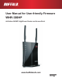
User Manual for User-friendly Firmware
WHR-300HP
AirStation NFINITI HighPower Router and AccessPoint
www.buffalotech.com
Contents
Chapter 1 - Introduction.................................................... 4
Professional or User-friendly?......................................................4
Package Contents........................................................................4
Hardware Overview.....................................................................5
Front Panel LED's........................................................................... 5
Back Panel...................................................................................... 7
Top.................................................................................................. 8
Bottom............................................................................................. 8
Chapter 2 - Placing Your AirStation................................. 9
Antenna Placement......................................................................9
Vertical Placement.......................................................................9
Horizontal Placement...................................................................10
Wall Mounting..............................................................................11
Chapter 3 - Installation......................................................12
Initial Setup..................................................................................12
Changing Firmware......................................................................19
Chapter 4 - Configuration................................................. 21
Accessing the Web-based Configuration Interface......................21
Configuration Menu (Router Mode).............................................23
Configuration Menu (Bridge Mode)..............................................25
Setup............................................................................................27
WAN/LAN.....................................................................................29
Internet............................................................................................ 29
PPPoE............................................................................................ 30
DDNS.............................................................................................. 33
-1-
VPN Server..................................................................................... 35
LAN................................................................................................. 37
DHCP.............................................................................................. 39
NAT................................................................................................. 40
Routing............................................................................................ 41
Wireless.......................................................................................42
WPS................................................................................................ 42
Basic............................................................................................... 43
Advanced........................................................................................ 46
WMM............................................................................................... 47
MAC Filter....................................................................................... 49
WDS................................................................................................ 50
AOSS.............................................................................................. 52
Multicast Control............................................................................. 54
Firewall.........................................................................................55
Firewall............................................................................................ 55
IP Filter............................................................................................ 57
VPN Passthrough........................................................................... 58
Games/Apps................................................................................59
Port Forwarding.............................................................................. 59
DMZ................................................................................................ 60
UPnP............................................................................................... 61
QoS................................................................................................. 62
Admin...........................................................................................63
Name.............................................................................................. 63
Password........................................................................................ 64
Time/Date....................................................................................... 65
NTP................................................................................................. 66
ECO................................................................................................ 67
Access............................................................................................ 69
Log.................................................................................................. 70
Save/Restore.................................................................................. 71
Initialize/Restart.............................................................................. 72
Update............................................................................................ 73
-2-
Diagnostic....................................................................................74
System Info..................................................................................... 74
Logs................................................................................................ 76
Packet Info...................................................................................... 77
Client Monitor.................................................................................. 78
Ping................................................................................................. 79
Chapter 5 - Connect to a Wireless Network.................... 80
Automatic Secure Setup (AOSS/WPS)........................................80
Windows 7/Vista (Client Manager V).............................................. 81
Windows XP (Client Manager 3)..................................................... 82
Mac OS X (AOSS Assistant)........................................................... 83
Other Devices (e.g. Game Console)............................................... 84
Manual Setup...............................................................................84
Windows 7 (WLAN AutoConfig)...................................................... 84
Windows Vista (WLAN AutoConfig)................................................ 85
Windows XP (Wireless Zero Configuration).................................... 88
Mac OS X (Wi-Fi)............................................................................ 89
Chapter 6 - Troubleshooting............................................. 90
Cannot connect to the Internet over wired connection................90
Cannot access the web-based configuration interface................90
Cannot connect to the network wirelessly....................................91
You forgot the AirStation's SSID, Encryption Key, or Password..91
The link speed is slower than 300 Mbps (Maximum link speed is
only 130 Mbps)............................................................................91
Other Tips....................................................................................92
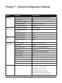
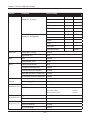
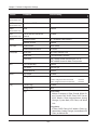
Chapter 7 - Default Configuration Settings..................... 95
-3-
Chapter 1 - Introduction
Professional or User-friendly?
This AirStation wireless router comes with two different firmware packages. You may use either the
dd-wrt-based professional firmware or the simple user-friendly firmware. By default, the professional
firmware is preinstalled. Turn to page 19 for instructions on switching between the two firmware
packages.
Note: Most of this manual documents the User-friendly firmware. For more information on the
dd-wrt-based Professional firmware, consult the help files in its web-based configuration
interface or go to www.dd-wrt.com/wiki.
Package Contents
The following items are included with your AirStation. If any of the items are missing, please contact
your vender.
• Main unit...............................................................................................1
• Detachable antennas ......................................................................2
• AC adapter............................................................................................1
• Stand for vertical/wall-mounting................................................1
• Screws for wall-mounting...............................................................2
• LAN cable..............................................................................................1
• AirStation Utility CD..........................................................................1
• Quick Setup Guide............................................................................1
• Setup Card............................................................................................1
-4-
Chapter 1 Introduction
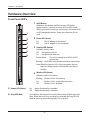
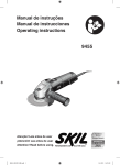
Hardware Overview
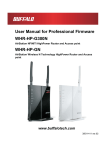
Front Panel LED's
1
AOSS Button
Hold down this button until the Security LED flashes
(approximately 1 second) to initiate AOSS or WPS mode,
allowing the unit to exchange security keys with other AOSS
or WPS compatible devices. Power must be on for this to
work.
2
Power LED (Green)
On: The AC adapter is connected
Off: The AC adapter is not connected
1
2
3
4
3
5
6
Off: Encryption is not set
On: Encryption has been set
Double blink:
The unit is waiting for an AOSS or WPS
security key
Blinking: AOSS/WPS error; failed to exchange security keys
Note: When the Security LED is lit, an encryption key has been set. Wireless clients will need the same key to
connect.
4
5
Router LED (Green)
On: Off:
Security LED (Amber)
Indicates security status.
Wireless LED (Green)
Indicates wireless LAN status
Blinking: Wireless LAN is transmitting
On: Wireless LAN is enabled but not active
Off:
Wireless LAN is disabled
Router functionality is enabled
Router functionality is disabled
6
Diag LED (Red)
This indicates the status of the unit by the number of blinks per cycle.
Note: When the unit is first turned on or restarted, the Diag LED will blink for almost a minute during boot. This is normal.
-5-
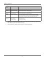
Chapter 1 Introduction
Diag LED
status
Meaning
Status
2 blinks *1
Flash ROM error
Cannot read or write to the flash memory.
3 blinks *
Ethernet (wired) LAN
error
Ethernet LAN controller is malfunctioning.
4 blinks *1
Wireless LAN error
Wireless LAN controller is malfunctioning.
5 blinks
IP address setting error
Because the network addresses of both the Internet port (WAN
port) and the LAN port are the same, it is not possible to establish
communication. Change the LAN side IP address of this unit.
1
Continuously Updating the firmware
blinking *2
Saving settings
Initializing settings
Updating the firmware.
Saving the settings.
Initializing the settings.
*1
Unplug the AC adapter from the wall socket, wait for a few seconds, and then plug it again. If the
light still flashes, please contact technical support.
*2
Never unplug the AC adapter while the Diag LED is blinking continuously.
-6-
Chapter 1 Introduction
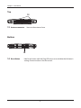
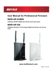
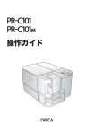
Back Panel
7
Router Switch
Switches router mode between enabled, disabled, and auto.
ÒÏÕÔÅÒ
ÏÎ
ÏÆÆ
ÁÕÔÏ
7
On: Router is enabled (router mode).
Off: Router is disabled (bridge/AP mode).
Auto: This switches between modes automatically based
on whether or not another router is detected on the
Internet port. The default setting for this switch is
Auto.
8
LAN LED (Green)
On: An Ethernet device is connected.
Flashing: An Ethernet device is communicating.
ÌÁÎ
ᴮ
ᴯ
8
9
9
ᴰ
ᴱ
LAN Port
Connect your computer, hub, or other Ethernet devices to
these ports. This switching hub supports 10 Mbps and 100
Mbps connections.
ÉÎÔÅÒÎÅÔ
11
10
ÐÏ×ÅÒ
12
10 Internet LED (Green)
On: The Internet (WAN) port is connected.
Flashing: The Internet port is transmitting data.
11
Internet Port
Connect your cable or DSL modem to this port. 10 Mbps and 100 Mbps
connections are supported. In bridge/AP mode (router switch off ), the
Internet port becomes a regular LAN port, for a total of 5 usable LAN ports.
12
DC Connector
Connect the included AC adapter.
-7-
Chapter 1 Introduction
Top
13
13
Antenna connector
Screw on the antennas here.
Bottom
ᵏᵂᵐᵂᵑ
14
14
Reset Button
Hold in this button until the Diag LED comes on to initialize the AirStation’s
settings. Power must be on for this to work.
-8-
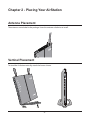
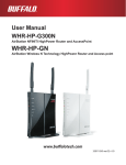
Chapter 2 - Placing Your AirStation
Antenna Placement
The antennas are included in the package. Screw the antennas clockwise to install.
Ò
×Å
Vertical Placement
To stand the AirStation vertically, attach the base as shown.
2
1
1
-9-
Chapter 2 Placing Your AirStation
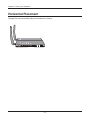
Horizontal Placement
To place the unit horizontally, adjust the antennas as shown.
- 10 -
Chapter 2 Placing Your AirStation
Wall Mounting
1
To wall-mount, attach the stand
with screws as shown.
8.5 cm
(~3.3 inches)
2
Place the center of the AirStation on the
center of the stand and slide downward
to lock in place.
- 11 -
Chapter 3 - Installation
Initial Setup
Using AirStation as a Router or an Access Point
To use the AirStation as a router or an access point, configure as below.
1
Turn off your computer and modem.
2
2) disconnect
2) disconnect
1) turn off the computer
OFF
Unplug the LAN cable that connects
your computer and modem.
computer
modem
3
Make sure the mode switch on the back of
the AirStation is in the auto position.
ROUTER
ER
TY
URI
SEC
ESS
REL
WEI
ROU
DIA
Confirm that the
switch is positioned to
[AUTO].
ON
OFF
AUTO
POW
TER
G
LAN
1
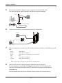
4
Connect one end of the LAN cable to the modem, and connect the other end to the Internet
port of the AirStation. Turn on your modem.
ROUTER
ON
OFF
AUTO
LAN
1
1) connect
2
3
4
2) connect
INTERNET
INTERNET port
POWER
modem
LAN cable
AirStation
- 12 -
Chapter 3 Installation
5
Connect the AirStation’s LAN port to your computer with another LAN cable.
Turn on the AirStation, wait 60 seconds, and then turn on your computer.
AirStation
1) connect
ROUTER
ON
OFF
AUTO
LAN
1
PC
2
1) connect
3
LAN cable
4
INTERNET
POWER
2) connect the power supply
power outlet
6
Confirm that the devices are connected correctly as shown below.
computer
ON
modem
power outlet
7
After the computer has booted, the LEDs on the AirStation should be in the following condition:
Power
Wireless
Router
Diag
LAN
Internet
Green LED on
Green LED on or blinking
Green LED on or off depending on your network
Off
Green LED on or blinking
Green LED on or blinking
Refer to pages page 5 and page 7 for LED locations and other details.
8
Launch a web browser. If the home page is displayed, setup is complete.
If username and password fields are displayed, enter “admin” for the username and
“password” for the password, then click [OK]. Follow the instructions on the screen to
complete setup.
You’ve completed initial setup of your AirStation. Refer to Chapter 4 for advanced settings.
- 13 -
Chapter 3 Installation
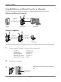
Using AirStation as an Ethernet Converter or a Repeater
To use the AirStation as an Ethernet converter or a repeater, follow the directions below.
Using as an Ethernet Converter:
wireless
wired
ER
POW
SEC
URI
WEI
TY
ESS
REL
TER
ROU
DIA
router
G
AirStation
computer
Using as a repeater:
wireless
wireless
ER
ER
POW
SEC
URI
WEI
POW
TY
SEC
ESS
REL
DIA
URI
WEI
TER
TY
ESS
REL
TER
ROU
ROU
G
DIA
router
G
AirStation
computer
This section describes manual configuration. You can also use AOSS or WPS for automatic configuration.
1
Set your computer’s IP address settings as follows (Appendix C).
2
IP Address
Subnet mask
Default gateway
Preferred DNS server
Alternate DNS server
192.168.11.80
255.255.255.0
192.168.11.1
192.168.11.1
blank
Shut down your computer.
3
Move the switch from the auto position to
off.
ROUTER
ER
POW
TY
URI
SEC
ESS
REL
WEI
ROU
DIA
TER
ON
OFF
AUTO
G
LAN
Move the switch from
the auto position to
off.
1
- 14 -
Chapter 3 Installation
4
Connect the AirStation’s LAN port to your computer with another LAN cable.
Turn on the AirStation, wait 60 seconds, and then turn on your computer.
AirStation
1) connect
ROUTER
ON
OFF
AUTO
LAN
1
PC
2
1) connect
3
LAN cable
4
INTERNET
POWER
2) connect the power supply
power outlet
5
Confirm that the devices are connected correctly as shown below.
computer
ON
power outlet
6
After the computer has booted, the LEDs on the AirStation should be in the following condition:
Power
Wireless
Router
Diag
LAN
Green LED on
Green LED on or blinking
Off
Off
Green LED on or blinking
Refer to pages page 5 and page 7 for LED locations and other details.
- 15 -
Chapter 3 Installation
7
Launch a web browser.
8
Enter the LAN IP address of the AirStation in the
address field, then press the Enter key.
Notes:
•The default IP address of the AirStation is 192.168.11.100 in access point mode.
•If you have changed the IP address of the AirStation, enter that IP address.
9
Enter “admin” for the username and
“password” for the password and click [OK].
Note:
10
Click [Wireless] > [WDS].
- 16 -
If you forget your password, hold down the
reset button (page 8) to initialize all settings.
Note that all other settings will also revert to
their default values.
Chapter 3 Installation
11
If the device you connect supports WDS such as the WHR-300HP, WZR-300HP and WZR600DHP, select [Slave] from the [Specify Master/Slave] menu and click [Search].
If the device you connect doesn’t support WDS, select [Slave(EC)] from the [Specify Master/
Slave] menu and click [Search].
Slave(EC):
Slave:
ER
POW
ITY
UR
SEC
S
LES
IRE
WE
R
UTE
RO
DIA
G
ER
POW
ER
POW
SEC
URI
WEI
TY
SEC
ESS
REL
DIA
BUFFALO Wireless
router with WDS
12
URI
WEI
TY
ESS
REL
TER
TER
ROU
ROU
G
DIA
AirStation
router
G
AirStation
Once the list of the access points is displayed, select the access point you are going to connect to, then click [Select].
If the access point you are going to connect to is not displayed, click [Search Again].
- 17 -
Chapter 3 Installation
13
Enter the encryption settings and password (“key”) for the access point you are connecting
to, then click [Apply].
14
Change your computer’s IP address settings back to their former values.
ex) IP Address
DNS server
Obtain an IP address automatically
Obtain DNS server address automatically
Note: If using the AirStation as a repeater, unplug the LAN cable from your computer. You’re now connected to the AirStation wirelessly.
15
Launch a web browser. If your home page is displayed, setup is complete.
- 18 -
Chapter 3 Installation
Changing Firmware
To change between the professional firmware (dd-wrt) and the user-friendly firmware, follow the
steps below.
1
Open the configuration Interface of the AirStation.
2
To replace the professional firmware with the user-friendly firmware, click [Administration] >
[Firmware Upgrade].
To replace the user-friendly firmware with the professional firmware, go to [Easy Setup] and
click [Update AirStation Firmware].
- 19 -
Chapter 3 Installation
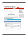
3
Click [Browse...] to select the firmware file, and click [Upgrade] or [Apply].
Note: The firmware files are contained in the “Firmware” folder of the utility CD.
Professional firmware (dd-wrt) update screen:
User-friendly firmware update screen:
- 20 -
Chapter 4 - Configuration
The web-based configuration interface lets you change AirStation settings. Don’t change these
settings unless you know what you’re doing.
Accessing the Web-based Configuration Interface
To configure the AirStation’s advanced settings manually, log in to the web-based configuration interface
as shown below.
1
Launch a web browser.
2
Enter the AirStation’s LAN-side IP address in the address
field, and press the enter key.
Note: ·
The AirStation’s default LAN-side IP address depends on the position of the mode switch.
In router mode: 192.168.11.1
In bridge mode: 192.168.11.100
If the router switch is set to auto and the unit is in bridge mode, then the AirStation’s IP address was
assigned by an external DHCP server.
· If you changed the IP address of the AirStation, then use the new IP address.
3
Enter “admin” for the username and “password”
for the password and click [OK].
Note:
- 21 -
If you forget your password, hold down the
reset button (page 8) to initialize all settings.
Note that all other settings will also revert to
their default values.
Chapter 4 Configuration
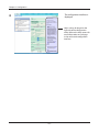
4
The configuration interface is
displayed.
Help is always displayed on the
right side of the configuration
utility. Refer to the help screens for
more information on each page
in the web-based configuration
interface.
- 22 -
Chapter 4 Configuration
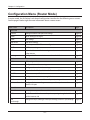
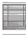
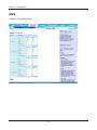
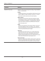
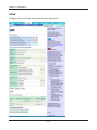
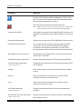
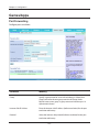
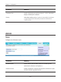
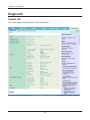
Configuration Menu (Router Mode)
In router mode, the AirStation’s web-based configuration interface has the following menu screens.
See the pages listed at right for more information about a menu screen.
Main screen
Descriptions
Page
Internet
Configure Internet side port and settings
page 29
PPPoE
PPPoE settings (DSL login)
page 30
DDNS
DNS settings
page 33
VPN Server
VPN server settings
page 35
LAN
LAN side port and DHCP server configuration
page 37
DHCP
DHCP lease settings
page 39
NAT
Network address translation settings, used to connect LAN side devices
to the Internet
page 40
Routing
Configure the IP communication route that the AirStation uses
page 41
WPS
WPS settings and status
page 42
Basic
Configure basic wireless settings
page 43
Advanced
Configure advanced wireless settings
page 46
WMM
Set priorities for Wireless Multimedia Extensions (Wi-Fi Multimedia)
page 47
MAC Filter
Limit access to specific devices
page 49
WDS
Configure communication among AirStation
page 50
AOSS
AOSS (AirStation One-touch Secure System) settings and status
page 52
Multicast Control
Configure limits on sending unnecessary multicast packets to the
wireless LAN port
page 54
Firewall
Protect your computer from outside intruders
page 55
IP Filter
Edit IP filters which relates to the packets passing through the LAN side page 57
and the Internet side
VPN
Passthrough
Configure IPv6 passthrough, PPPoE passthrough, and PPTP passthrough
WAN/LAN
Wireless
Firewall
- 23 -
page 58
Chapter 4 Configuration
Games/Apps
Port Forwarding
Configure port translation and exceptions for games and other programs page 59
DMZ
Configure a destination to transfer communication packets without a
LAN side destination.
page 60
UPnP
Configure UPnP (Universal Plug and Play)
page 61
QoS
Configure priority for packets that require a certain data flow
page 62
Name
Configure the AirStation’s name
page 63
Password
Configure the AirStation’s login password for access to configuration
utilities
page 64
Time/Date
Configure the AirStation’s internal clock
page 65
NTP
Configure the AirStation to synchronize with an NTP server to
automatically set the AirStation’s internal clock
page 66
ECO
Configure the AirStation’s ECO Mode.
page 67
Access
Configure access restrictions to the AirStation’s configuration utilities
page 69
Log
Configure a syslog server to manage the AirStation’s logs
page 70
Save/Restore
Save or restore the AirStation’s configuration from a configuration file
page 71
Initialize/Restart
Initialize the AirStation or reboot it
page 72
Update
Update the AirStation’s firmware
page 73
System Info
View current system information for the AirStation
page 74
Logs
Check the AirStation’s logs
page 76
Packet Info
View all packets transferred by the AirStation
page 77
Client Monitor
View all devices currently connected to the AirStation
page 78
Ping
Test the AirStation’s connection to other devices on the network
page 79
Admin
Diagnostic
Logout
Click this to log out of the AirStation’s web-based configuration interface.
Manuals & Utilities
Click this to display download pages for Manuals and Utilities.
- 24 -
Chapter 4 Configuration
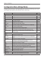
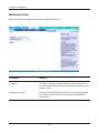
Configuration Menu (Bridge Mode)
In bridge mode, the AirStation’s web-based configuration interface has the following menu screens.
See the pages listed at right for more information about a menu screen.
Main screen
Descriptions
Page
LAN
Configure LAN side ports and devices
page 37
Routing
Configure the IP communication route that the AirStation uses
page 41
WPS
WPS settings and status
page 42
Basic
Configure basic wireless settings
page 43
Advanced
Configure advanced wireless settings
page 46
WMM
Set priorities for Wireless Multimedia Extensions (Wi-Fi Multimedia)
page 47
MAC Filter
Limit access to specific devices
page 49
WDS
Configure communication among AirStation
page 50
AOSS
AOSS (AirStation One-touch Secure System) settings and status
page 52
Multicast Control
Configure limits on sending unnecessary multicast packets to the
wireless LAN port
page 54
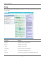
Name
Configure the AirStation’s name
page 63
Password
Configure the AirStation’s login password for access to configuration
utilities
page 64
Time/Date
Configure the AirStation’s internal clock
page 65
NTP
Configure the AirStation to synchronize with an NTP server to
automatically set the AirStation’s internal clock
page 66
ECO
Configure the AirStation’s ECO Mode.
page 67
Access
Configure access restrictions to the AirStation’s configuration utilities
page 69
Log
Configure a syslog server to manage the AirStation’s logs
page 70
Save/Restore
Save or restore the AirStation’s configuration from a configuration file
page 71
Initialize/Restart
Initialize the AirStation or reboot it
page 72
Update
Update the AirStation’s firmware
page 73
View current system information for the AirStation
page 74
LAN Config
Wireless
Admin
Diagnostic
System Info
- 25 -
Chapter 4 Configuration
Logs
Check the AirStation’s logs
page 76
Packet Info
View all packets transferred by the AirStation
page 77
Client Monitor
View all devices currently connected to the AirStation
page 78
Ping
Test the AirStation’s connection to other devices on the network
page 79
Logout
Click this to log out of the AirStation’s web-based configuration interface.
Manuals & Utilities
Click this to display download pages for Manuals and Utilities.
- 26 -
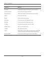
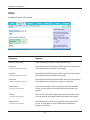
Chapter 4 Configuration
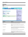
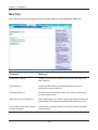
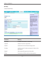
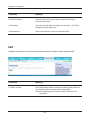
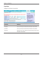
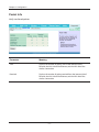
Setup
This is the home page of the configuration interface. You can verify settings and the status of the
AirStation here.
Parameter
Meaning
WAN/LAN
Configure WAN side network settings.
Wireless
Configure wireless settings.
Firewall
Configure security settings.
Games/Apps
Open ports for games and applications.
Admin
Open the Admin configuration screen.
Diagnostic
Gives information and tools for troubleshooting the network.
- 27 -
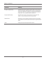
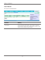
Chapter 4 Configuration
Parameter
Meaning
Easy Setup
Automatically configures the AirStation’s internet connection.
Internet Connection
Displays the current internet connection.
Check Connection
Checks if the AirStation is connected to the Internet properly.
Refresh
Click to refresh the display.
Wireless
Displays current wireless settings.
AOSS Setup
Click to display the AOSS configuration screen.
WPS Setup
Click to display the WPS configuration screen.
ECO Mode
This indicates the operating status of ECO Mode.
Network Services
Shows a list of network services.
Language
Select the language you use.
Logout
Log out of the AirStation’s web-based configuration interface. After
5 minutes of inactivity, the AirStation will log off automatically.
Manuals & Utilities
Click to display download pages for Manuals and Utilities.
- 28 -
Chapter 4 Configuration
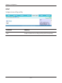
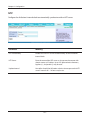
WAN/LAN
Internet
The screen to configure a port of the Internet side.
Parameter
Meaning
Method of Acquiring IP Address
Specifies how the current WAN-side IP address was obtained.
Default Gateway
Specify an IP address for the default gateway.
DNS Name Server Address
Specify an IP address for the DNS server.
Internet MAC Address
Configure the Internet side MAC address.
Note: Configuring an improper MAC address may make the AirStation
unusable. Change this setting at your own risk.
MTU size of Internet Port
Values between 578 to 1500 bytes may be entered.
- 29 -
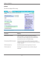
Chapter 4 Configuration
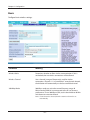
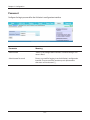
PPPoE
The screen to configure PPPoE settings.
Parameter
Meaning
Default PPPoE Connection
If you have registered multiple connection destinations in
PPPoE Connection List, connection destinations selected here
have priority. You need to configure the route to which PPPoE is
connected to if you don’t use the default setting.
IP Unnumbered PPPoE Connection
Select the destination from the PPPoE Connection List which is
used when specifying [Use IP Unnumbered] in Method of Acquiring
IP Address (page 29).
PPPoE Connection List
Edit PPPoE destination. You can register up to 5 sessions.
Edit Connection List
Click this button to display the screen to edit the settings of
destination.
- 30 -
Chapter 4 Configuration
Parameter
Meaning
PPPoE Connection No.
Click [Edit Connection List] to display.
Name of Connection
Enter a name to identify the connection. You may enter up to 32
alphanumerical characters and symbols.
Username
Enter the username specified by your provider for PPPoE. You may
enter up to 64 alphanumerical characters and symbols.
Password
Enter the password specified by your provider for PPPoE. You may
enter up to 64 alphanumerical characters and symbols.
Service Name
Fill in this field only when your provider specifies a Service Name.
Leave blank otherwise. You may enter up to 64 alphanumerical
characters and symbols.
Connection Type
Specifies the timing for the AirStation to connect to your provider.
Automatic Disconnection
Set time to disconnect after communication is stopped when the
connection method is set to [Connection on Demand] or [Manual].
You can enter up to 1440 minutes.
Authorization
Configure an authorization method with a provider.
MTU Size
Configure the MTU value between 578 and 1492 bytes.
MRU Size
Configure the MRU (Maximum Receive Unit) value between 578
and 1492 bytes.
Keep Alive
If Keep Alive is enabled, the AirStation issues LCP echo requests
to maintain the connection with the PPPoE server once a minute.
If the server does not respond after 6 minutes, then the line is
considered disconnected and the AirStation will terminate the
connection. If your PPPoE connection is often disconnected,
disable Keep Alive.
Preferred Connections
Displays connections that you’ve added to the preferred connection
list.
- 31 -
Chapter 4 Configuration
Parameter
Meaning
Edit Preferred Connections
Click this button to display the screen to edit the settings of
connection destination route
Preferred PPPoE Connection
This is displayed when clicking [Edit Preferred Connections].
Name
This will be the name of the connection in the PPPoE connection
list.
Destination Address
The AirStation will always use this connection to send data to this
address.
Source Address
The AirStation will always use this connection to receive data from
this address.
- 32 -
Chapter 4 Configuration
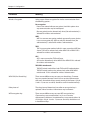
DDNS
Configure Dynamic DNS settings.
Parameter
Meaning
Dynamic DNS Service
Select a provider (DynDNS or TZO) for dynamic DNS.
Username
Enter the username for the dynamic DNS service. You may enter up
to 64 alphanumerical characters and symbols.
Only when DynDNS is selected
Password
Only when DynDNS is selected
Hostname
Only when DynDNS is selected
Email Address
Only when selecting TZO
TZO Key
Only when selecting TZO
Domain Name
Only when selecting TZO
Enter the password for the dynamic DNS service. You may enter up
to 64 alphanumerical characters and symbols.
Enter the hostname for the dynamic DNS service. You may enter up
to 255 alphanumerical characters, hyphens, and periods.
Enter the email address which is registered to the dynamic DNS
service. You may enter up to 64 alphanumerical characters and
symbols.
Enter the TZO Key which is registered to the dynamic DNS service.
You may enter up to 64 alphanumerical characters and symbols.
Enter the domain name which is registered to the dynamic DNS
service. You may enter up to 255 alphanumerical characters,
hyphens, and periods.
- 33 -
Chapter 4 Configuration
Parameter
Meaning
IP Address Update Period
Specifies the period to notify the dynamic DNS service provider of
the current IP address. When DynDNS is selected, set it between 0
and 35 days. When TZO is selected, set it between 0 and 99 days. If
0 (zero) day is set, no periodic update is performed.
Internet-Side IP Address
The WAN-side IP address of the AirStation’s Internet port. This
address is sent to the dynamic DNS service provider.
Domain Name
The domain name assigned by the dynamic DNS Service provider.
The AirStation can be accessed from the Internet using this domain
name.
Status
Displays the status of the dynamic DNS service.
- 34 -
Chapter 4 Configuration
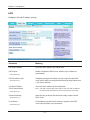
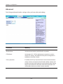
VPN Server
Configure a VPN server.
- 35 -
Chapter 4 Configuration
Parameter
Meaning
Auto Input
Click to generate a random IP address.
LAN Side IP Address
Set a LAN side IP address and subnet mask.
DHCP Server
If enabled, the DHCP server will assign LAN-side IP addresses automatically.
DHCP IP Address Pool
You may choose the range of IP addresses assigned by the DHCP server and
select IP addresses to be excluded from that range. Values from 1-256 may
be entered.
PPTP Server
Enable to use a PPTP server.
Authorization Type
Select the authentication method for PPTP connection.
Server IP Address
Select the server IP address.
Client IP Address
Select the IP address range.
DNS Server IP Address
Set the DNS server IP address for the DNS server to issue to clients.
WINS Server IP Address
Set the WINS server IP address for the WINS server to issue to clients.
MTU/MRU Value
Configure MTU (Maximum Transmission Unit) / MRU (Maximum
Receive Unit) between 578 and 1500 which is used during
transmission on PPTP.
Edit PPTP User List
Click to edit user information.
Add new user
Click [Edit PPTP User List] to display.
Advanced Settings
Username
Enter the username to connect to the PPTP server. You may enter
up to 16 alphanumerical characters and symbols.
Password
Enter the password to connect to the PPTP server. You may enter
up to 16 alphanumerical characters and symbols.
Method of Acquiring IP Address
Select the method to be used to assign the IP address is assigned
to the PPTP client.
PPTP User List
Displays the PPTP connection user information.
- 36 -
Chapter 4 Configuration
LAN
Configure LAN-side IP address settings.
Parameter
Meaning
LAN Side IP Address
Set a LAN side IP address and subnet mask.
DHCP Server
Enable or disable the DHCP server, which assigns IP addresses
automatically.
Router Mode only
DHCP IP Address Pool
Router Mode only
LAN Side IP Address
(For IP Unnumbered)
Router Mode only
Advanced Settings
Router Mode only
Lease Period
Router Mode only
Configure the range of IP addresses to be assigned by the DHCP
server and IP addresses to be excluded from that range. Values from
1-256 may be entered.
Set a LAN side IP address for IP unnumbered.
Note: A PC with a normal LAN side IP address and a PC with an LAN side
IP address for IP Unnumbered cannot communicate each other.
Select [Display] to display the advanced settings options for the
DHCP server.
Set the effective period of an IP address assigned by the DHCP
server. Up to 999 hours may be entered.
- 37 -
Chapter 4 Configuration
Parameter
Meaning
Default Gateway
Router Mode only
Set the default gateway IP address for the DHCP server to issue to
clients.
DNS Servers
Set the DNS server IP address for the DHCP server to issue to clients.
Router Mode only
WINS Server
Router Mode only
Domain Name
Set the WINS server IP address for the DHCP server to issue to
clients.
Router Mode only
Set the domain name for the DHCP server to issue to clients. You
may enter up to 64 alphanumerical characters, hyphens, and
periods.
Default Gateway
Set the default gateway IP address.
Bridge Mode only
DNS Server Address
Set the DNS server IP address.
Bridge Mode only
- 38 -
Chapter 4 Configuration
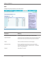
DHCP
Configure DHCP leases.
Parameter
Meaning
IP Address
Enter an IP address to lease manually. The IP address should be
from the same subnet as the DHCP scope, but not be within the
range that DHCP is assigning to other devices.
MAC Address
Enter the MAC address which identifies the client.
Current DHCP Clients
Displays information for current leases. An IP address which is
leased automatically can be changed to be leased manually by
clicking [Manual Assignment].
- 39 -
Chapter 4 Configuration
NAT
NAT (network address translation) allows your private LAN side network devices to communicate
with the Internet.
Parameter
Meaning
Address Translation
Enable to use Network Address Translation.
Log Output of Deleted Packets
Enable to log deleted packets (such as errors) from address
translation.
- 40 -
Chapter 4 Configuration
Routing
Configure the AirStation’s IP communication routes.
Parameter
Meaning
Destination Address
Adds a destination IP address and subnet mask to a routing table.
Gateway
Adds a gateway address to a routing table.
Metric
The metric is the maximum number of router hops a packet may
take on the way to its destination address. Values between 1 and 15
may be entered. The default value is 15.
Routing
Manual entries will appear here after being added.
- 41 -
Chapter 4 Configuration
Wireless
WPS
Configure WPS settings.
Parameter
Meaning
WPS
Enable to use WPS automatic configuration.
External Registrar
Enable to accept external configure requests from other WPS
devices.
Note: External configure requests will not be accepted if AOSS is in use.
AirStation PIN
Displays the PIN code of the AirStation. Clicking [Generate PIN]
will generate a new PIN code. This code can be entered into other
wireless devices that support WPS.
Enrollee PIN
Enter the PIN code for the other wireless device and click [OK].
WPS status
Displays [configured] if all available wireless bands are
configured. Displays [unconfigured] if at least one wireless band is
unconfigured.
- 42 -
Chapter 4 Configuration
Basic
Configure basic wireless settings.
Parameter
Meaning
Wireless Radio
Determines whether to allow wireless communication. If this is
unchecked, then no wireless connections will be allowed.
Wireless Channel
Sets a channel (a range of frequencies) used for wireless
connections. Channels 1-11 are available. If auto-channel selected,
the AirStation will automatically use the best available channel.
300 Mbps Mode
300 Mbps mode uses twice the normal frequency range, 40
MHz instead of 20 MHz. In uncongested areas this can increase
performance. To use 300 Mbps mode, set the bandwidth to 40 MHz
and choose an extension channel.
Note: If auto-channel is selected, then the extension channel is set
automatically.
- 43 -
Chapter 4 Configuration
Parameter
Meaning
Broadcast SSID
If [Allow] is checked, then the AirStation will respond to SSID
searches from wireless devices by broadcasting its SSID. If [Allow] is
unchecked, then the AirStation ignore SSID searches from wireless
devices.
Allow multiple SSIDs
Use Single SSID
Clicking [Allow multiple SSIDs] will enable Multi Security, allowing
the use of multiple SSIDs, each with different wireless security
settings. Clicking [Use Single SSID] will disable Multi Security.
The AirStation will then allow one SSID and one type of wireless
security.
Note: When using Multi Security, enable at least one of the following:
SSID1, SSID2, or SSID3.
SSID1
Multi Security SSID1 can use WPA-PSK-TKIP or WPA/WPA2-Mixed for
wireless security.
SSID2
Multi Security SSID2 can use WPA-PSK-AES for wireless security.
SSID3
Multi Security SSID3 can use WEP for wireless security.
Separate
When [Use] is checked, wireless devices connected to the AirStation
can communicate only with the Internet side, not with each other.
SSID
SSIDs may contain 1-32 alphanumeric characters.
Wireless Authentication
Choose an authentication method for wireless connections.
- 44 -
Chapter 4 Configuration
Parameter
Meaning
Wireless Encryption
Select a type of data encryption for wireless communication from
the following options:
No encryption
Data is transmitted without encryption. Avoid this option since
any communication may be intercepted.
[No encryption] can be selected only when [No authentication] is
selected for wireless authentication.
WEP
WEP is a common encryption method supported by most devices.
It uses an encryption key. WEP can only be selected when [No
authentication] is selected for wireless authentication.
TKIP
TKIP is an encryption method which is more secure than WEP, but
slower. TKIP can be selected only when WPA-PSK or WPA2-PSK is
selected for wireless authentication.
AES
AES is more secure than TKIP, and faster.
AES can be selected only when WPA-PSK or WPA2-PSK is selected
for wireless authentication.
TKIP/AES mixed mode
TKIP/AES mixed mode allows both TKIP and AES authentication.
TKIP/AES mixed mode can be selected only when WPA/WPA2
mixed mode - PSK is selected for wireless authentication.
WPA-PSK (Pre-Shared Key)
There are two different ways to enter pre-shared keys. Character
keys may contain between 8 and 63 case-sensitive alphanumeric
characters. Hexadecimal keys contain exactly 64 characters. Only 0 9 and a - f (not case-sensitive) should be used in hexadecimal keys.
Rekey Interval
The rekey interval determines how often an encryption key is
updated. Values from 0 to 1440 minutes may be entered.
WEP encryption key
There are two different ways to enter WEP encryption keys.
Character keys may contain either 5 or 13 case-sensitive
alphanumeric characters. Hexadecimal keys may contain either 10
or 26 digits. Only 0 - 9 and a - f (not case-sensitive) should be used
in hexadecimal keys.
- 45 -
Chapter 4 Configuration
Advanced
Don’t change advanced wireless settings unless you know what you’re doing.
Parameter
Meaning
Multicast Rate
Set the communication speed of multi-cast packets.
DTIM Period
Set the interval (1 -255) for the beacon to respond to a wireless
device. This setting is only effective when power management is
enabled on the wireless device.
Privacy Separator
If enabled, the Privacy Separator blocks communication between
wireless devices connected to the AirStation. Wireless devices will
be able to connect to the Internet but not with each other. Devices
that are connected to the AirStation with wired connections will
still be able to connect to wireless devices normally.
- 46 -
Chapter 4 Configuration
WMM
Configure QoS priorities here.
- 47 -
Chapter 4 Configuration
Parameter
Meaning
WMM-EDCA Parameters
You don't usually need to change these settings. Using the default
settings is recommended.
Priority
The following priorities may be applied to individual transmission
packets: (Highest) 8, (High) 4, (Normal) 2, and (Low) 1. From the
queue, these packets are processed in order of priority.
CWmin, CWmax
The maximum and minimum value of the contention window.
The contention window is used in the frame collision avoidance
structure performed in IEEE802.11, and generally the smaller the
value in the window, the higher the probability that the queue
obtains the right to send.
AIFSN
The interval to send frames. The unit of the AIFSN is a slot, just as
the window defined by CWmin and CWmax is. The smaller the
interval of sending frames, the faster the algorithm can restart. As
a result, the priority of the queue is higher.
TXOP Limit
The period of time that the queue can use after obtaining the
right to send. The unit is 32 ms. The longer this time, the more
frames can be sent per right to send. However, the que may
interfere with other packet transmissions. If TXOP Limit is set to 0
(zero), only one frame can be sent per right to send.
Admission Control
Restricts new frames from interfering with a previous queue. New
packets are prioritized lower until a queue of them is collected. As
the new queue accumulates more packets, its priority increases.
- 48 -
Chapter 4 Configuration
MAC Filter
This screen lets you restrict wireless access to wireless devices with specific MAC addresses.
Parameter
Meaning
Enforce MAC Filtering
Enable to restrict wireless connections to devices with registered
MAC addresses.
Registration List
Displays the MAC addresses of registered devices which are
permitted to connect wirelessly.
Edit Registration List
Click this button to add a MAC address of a wireless device to the
list of permitted devices.
MAC Addresses to be Registered
Enter a MAC address of a wireless device you permit to connect to
the AirStation. Click [Register] to add that MAC address to the list.
List of all clients that are associated
with this AirStation
Display the list of all MAC addresses of wireless devices connected
to the AirStation.
- 49 -
Chapter 4 Configuration
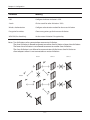
WDS
WDS bridging allows communication between AirStations.
Parameter
Meaning
WDS
Check to use WDS bridging.
Specify Master/Slave
Define this AirStation's role in a WDS bridge.
Master
This AirStation will the master in a WDS bridge. It will have the
Internet connection, and other AirStations in the bridge will be
connected through this AirStation.
Slave
Set AirStation as a slave.
This can be connected with the AirStation which is set as a master
by using WDS feature only if the Master AirStation supports WDS.
Slave (EC)
Set AirStation as a slave.
This uses Ethernet Converter to connect with the AirStation which
is set as a master, so it can be connected even though Master
AirStation does not support WDS.
Auto
Automatically switches between Master and Slave modes
depending on the surrounding network.
If an AirStation works as a router, it will automatically be set as a
master.
If the AirStation works as a bridge and a DHCP server exists
in the network, it will automatically be set as a master . If the
AirStation works as a bridge and no DHCP server is available, it
will automatically be set as a slave.
- 50 -
Chapter 4 Configuration
Parameter
Meaning
SSID
Configure the Master AirStation's SSID.
Search
Click to search for other AirStations' SSIDs.
Wireless Authentication
Configure authentication method for the master AirStation
Encryption for wireless
Choose encryption type for the master AirStation.
WPA-PSK (Pre-shared key)
Set the master AirStation's Encryption key.
Notes: Two AirStation can be connected per one master AirStation.
The slave AirStation is allowed to connect to another slave AirStation as lower slave AirStation.
The lower slave AirStation is not allowed to connect to another slave AirStation.
The slave AirStation is not allowed to communicate with the lower slave AirStation or
client adapters when it is not connected to a master AirStation.
Slave 1
Slave 2
Master
- 51 -
Slave 3
Chapter 4 Configuration
AOSS
Configure and use AirStation One-touch Secure System (AOSS).
- 52 -
Chapter 4 Configuration
Parameter
Meaning
Initiates AOSS automatic wireless configuration. Click this, then
press or click the AOSS button on your AOSS-compatible wireless
client. Repeat for additional AOSS clients.
Click this button to disconnect all AOSS connections.
Note: If AOSS connections are disconnected, the SSID and encryption keys
will be restored to their most recent settings before using AOSS.
Exclusive SSID for WEP
You may allow a separate SSID specifically for WEP connections. If
[disabled] is selected, then clients will not be able to connect with
WEP.
Encryption level expansion
Expands security method from TKIP to WPA/WPA2-PSK-mixed mode.
Dedicated WEP SSID isolation
Set a separate SSID and network segment specifically for WEP
connections. Devices connected with WEP will not be able
to communicate with devices connected using AES/TKIP. All
connected devices will be able to communicate with the internet.
Allow WEP for Game Console Only
When enabled, the AirStation allows wireless devices to connect
with 64-bit or 128-bit WEP.
AOSS Button on the AirStation Unit
Uncheck to disable the physical AOSS button on the AirStation.
Current Encryption Information
Displays the encryption type, SSID, and encryption key that AOSS
has configured.
AOSS Connection only
Random
Click to enter random values for SSID, encryption key, and other
settings.
KEY base
Click to return the SSID, encryption key, and other wireless
settings to the values on the Setup Card.
Reset
Click to return the SSID, encryption key, and other wireless
settings to their previous values.
AOSS Client Information
Displays basic information for AOSS clients connected to the
AirStation.
AOSS Connection only
AOSS Ethernet Converter Information
AOSS Connection only
Displays basic information for Ethernet converters connected to
the AirStation via AOSS.
- 53 -
Chapter 4 Configuration
Multicast Control
Restrict unnecessary multicast packets from wireless LAN ports.
Parameter
Meaning
Snooping
If enabled, snooping supervises multicast administrative packets
such as IGMP and restricts unnecessary multicast transfers to wired
or wireless ports.
Multicast Aging Time
Set the time to hold the data from multicast snooping in the range
of 1 to 3600 (seconds). Enter a value larger than the IGMP/MLD
query interval.
- 54 -
Chapter 4 Configuration
Firewall
Firewall
Parameter
Meaning
Log Output
Enable to output a log of firewall activity.
Basic Rules
Enable to use any of the quick filters. Preconfigured quick filters
include:
Prohibit NBT and Microsoft-DS routing
When enabled, this prevents Microsoft networking from
communicating between the LAN side and the WAN side. You
can configure this with PPPoE if you select [Use PPPoE client] or
[Use IP unnumbered] in Method of Acquiring IP address, or if Easy
Setup identified a PPPoE connection during setup.
- 55 -
Chapter 4 Configuration
Parameter
Meaning
Reject ident requests
Enabling this option will answer IDENT requests from the Internet
side with corresponding rejection packets. Enable this option
if you experience slow transfer speeds for network applications
such as email, ftp, or browsing. If you have configured transfer of
IDENT requests to the LAN side in the address translation settings
(DMZ or TCP port:113), that setting has higher priority, and
overrides this setting.
Block ping from Internet
If this is enabled, the AirStation will not respond to pings from the
Internet side. You can configure this with PPPoE if you select [Use
PPPoE client] or [Use IP unnumbered] in Method of Acquiring IP
address (page 29), or if Easy Setup identified a PPPoE connection
during setup.
- 56 -
Chapter 4 Configuration
IP Filter
Create and edit IP filters.
Parameter
Meaning
Log Output
If enabled, IP filter activity is saved to a log.
Operation
Specify how to process target packets.
Direction
Specify the transmission direction of target packets.
IP Address
Specify the sender's IP address and receiver's IP address of the
target packets.
Protocol
Select a protocol for target transmission packet.
IP Filter
Display the list of IP filters which have been registered.
- 57 -
Chapter 4 Configuration
VPN Passthrough
Configure IPv6 passthrough, PPPoE passthrough, and PPTP passthrough.
Parameter
Meaning
IPv6 Passthrough
Enable to use IPv6 Passthrough for address translation.
PPPoE Passthrough
Enable to use PPPoE bridge. Using PPPoE bridge lets you
automatically obtain an IP address from your provider using the
PPPoE protocol from your computer connected to the LAN side
because all PPPoE packets can pass through between the Internet
and LAN.
PPTP Passthrough
Enable to use PPTP Passthrough for address translation.
- 58 -
Chapter 4 Configuration
Games/Apps
Port Forwarding
Configure port translation.
Parameter
Meaning
Group
Specify a group name for a new rule to belong to. Select [New
Group] and enter the new group name in the Group Name
field to create a new group. A group name can include up to 16
alphanumeric letters.
Internet-Side IP Address
Enter the Internet side IP address (before translation) for the port
translation table entry.
Protocol
Select the Internet side protocol (before translation) for the port
translation table entry.
- 59 -
Chapter 4 Configuration
Parameter
Meaning
LAN Side IP Address
Enter the LAN side IP address (after translation) for the port
translation table entry.
LAN Side Port
Select the LAN side (after translation) port number (1 - 65535) for
the port translation table entry.
Forwarded Ports
Shows current entries in the port translation table.
DMZ
Configure a destination to transfer communication packets without a LAN side destination.
Parameter
Meaning
IP Address of DMZ
Enter the IP address of the destination to which packets which are
not routed by a port translation table are forwarded.
Note:RIP protocol packets (UDP port number 520) will not be
forwarded.
- 60 -
Chapter 4 Configuration
UPnP
Configure Universal Plug and Play.
Parameter
Meaning
UPnP
Enable or disable Universal Plug and Play (UPnP) functionality.
- 61 -
Chapter 4 Configuration
QoS
Configure the priority of packets sent to the Internet.
Parameter
Meaning
QoS for transmission to the Internet
Enable to give priority to specific types of Internet traffic.
Uplink Bandwidth
Specify the upstream bandwidth in kbps from the AirStation to the
Internet side. Set the actual value for the upstream bandwidth.
Enable
Check to enable desired entries, then click [apply].
Application Name
Enter an application name. Names may use up to 32 alpha
numerical characters, double or single tick marks ("'), quotation
marks (“), and semicolons (;).
Protocol
Select either TCP or UDP.
- 62 -
Chapter 4 Configuration
Parameter
Meaning
Destination Port
Specify a destination port with the value of 1 - 65535. If this field is
empty, a random port is selected.
Priority
Select high, medium or low. If packets do not qualify for classification
as a type on the list, then their priority is treated as a level between
medium and low.
Admin
Name
Configure the AirStation’s name.
Parameter
Meaning
AirStation Name
Enter a name for the AirStation. Names may include up to 64
alphanumeric characters and hyphens (-).
Network Services
Enable or disable this to display the computers and devices on your
network with their supported services.
- 63 -
Chapter 4 Configuration
Password
Configure the login password for the AirStation’s configuration interface.
Parameter
Meaning
Administrator
“admin” is the configuration interface’s username for login. This
name is fixed.
Administrator Password
Enter a password for logging in to the AirStation’s configuration
interface. The password may contain up to 8 alphanumeric
characters and underscores (_).
- 64 -
Chapter 4 Configuration
Time/Date
Configure the AirStation’s internal clock.
Parameter
Meaning
Local Date
You may manually set the date of the AirStation’s internal clock.
Local Time
You may manually set the time of the AirStation’s internal clock.
Time Zone
Specify the time zone (offset of Greenwich Mean Time) of the
AirStation's internal clock.
- 65 -
Chapter 4 Configuration
NTP
Configure the AirStation’s internal clock to automatically synchronize with an NTP server.
Parameter
Meaning
NTP Functionality
Enable to use an NTP server to automatically set the AirStation's
internal clock.
NTP Server
Enter the name of the NTP server as a hostname, hostname with
domain name, or IP address. Up to 255 alphanumeric characters,
hyphens (-), and periods (.) may be used.
Update Interval
How often should the AirStation submit a time request to the NTP
server? Intervals of 1 - 24 hours may be set.
- 66 -
Chapter 4 Configuration
ECO
Configure Eco mode from this screen.
- 67 -
Chapter 4 Configuration
Parameter
Meaning
Scheduling
Enable to schedule Eco Mode. If Eco Mode is enabled, AOSS will
function only when the AirStation is in Normal operating mode.
Weekly Schedule
Graphically displays the configured schedule.
Schedule Entry
Configure operational mode for time periods in the weekly schedule. If User Defined mode is chosen, configure it below.
User Defined Mode
Individual power saving elements may be configured for User Defined mode.
- 68 -
Chapter 4 Configuration
Access
You may restrict access to the AirStation’s settings screens.
Parameter
Meaning
Log Output
Enabling outputs a log of changes to access settings.
Prohibit configuration from wireless
LAN
If enabled, prevents access to settings screens from wirelessly
connected devices (only wired devices may configure).
Prohibit configuration from wired
LAN
If enabled, prevents access to settings screens from wired devices
(only wirelessly connected devices may configure).
Permit configuration from wired
Internet
If enabled, allows access to settings screens from network devices
on the Internet side.
Permitted IP Address
Displayed only if Internet side configuration is enabled. Enter the IP
address of the device that is permitted to configure the AirStation
remotely from the Internet side.
Permitted Port
Displayed only if Internet side configuration is enabled. Set a port
number (1 - 65535) if configuring the AirStation from the Internet
side.
- 69 -
Chapter 4 Configuration
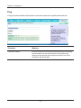
Log
You may use a syslog server to manage the AirStation’s logs.
Parameter
Meaning
Transfer Logs
Enable to send logs to a syslog server.
Syslog Server
Identify the syslog server by hostname, hostname with domain
name, or IP address. You may enter up to 255 alphanumeric
characters, hyphens (-), and underscores (_).
Logs
Choose which logs will be transferred to the syslog server.
- 70 -
Chapter 4 Configuration
Save/Restore
You may save your AirStation’s settings as a file and restore settings from that file later.
Parameter
Meaning
Save Current Settings
Clicking [Save] will save the current configuration of the AirStation
to a file. If the [Encrypt the configuration file with a password]
option is checked, then the configuration file will be password
protected with the password.
Restore Configuration from Backup
File
Restore the configuration of the AirStation from a saved
configuration file by clicking the [Browse...] button, navigating to
the configuration file, and then clicking Restore. If the configuration
file was password protected, then put a check next to [Enter
password], enter the password, and click [Restore].
- 71 -
Chapter 4 Configuration
Initialize/Restart
Reboot or initialize the AirStation.
Parameter
Meaning
Restart
Click [Restart Now] to restart the AirStation.
Initialize
Click [Initialize Now] to initialize and restart the AirStation.
- 72 -
Chapter 4 Configuration
Update
Update the AirStation’s firmware.
Parameter
Meaning
Firmware Version
Displays the current firmware version of the AirStation.
Update Method
Specify Local File
Updates from a firmware file stored on your computer.
Auto Update Online
Automatically updates to the latest firmware available.
Firmware File Name
Click [Browse...] to navigate to the firmware file on your computer
if [Specify Local File] was selected. You don’t need to specify the
firmware location if you’re using [Auto Update Online]. Click
[Update Firmware] to update the firmware.
- 73 -
Chapter 4 Configuration
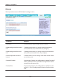
Diagnostic
System Info
This screen displays the AirStation’s system information.
- 74 -
Chapter 4 Configuration
Parameter
Meaning
Model
Displays the product name of the AirStation and the firmware
version.
AirStation Name
Displays the AirStation’s Name.
Mode Switch Status
Displays the status of the mode switch on the back of the
AirStation.
Operational Mode
Displays the current operational mode of the AirStation.
Internet
Displays the information about the Internet port.
LAN
Displays the information about the LAN port.
Wireless
Displays the wireless status.
WDS
Displays the current WDS status.
ECO Mode
Displays the operating status of ECO Mode.
- 75 -
Chapter 4 Configuration
Logs
Check the AirStation’s logs.
Parameter
Meaning
Display logs
Choose the logs to display.
Logs
Displays the logs.
- 76 -
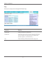
Chapter 4 Configuration
Packet Info
Verify transferred packets.
Parameter
Meaning
Sent
Displays the number of packets sent to the Internet side of
Ethernet, the LAN side of the Ethernet, and the LAN side of the
wireless connection.
Received
Displays the number of packet received from the Internet side of
Ethernet, the LAN side of the Ethernet, and the LAN side of the
wireless connection.
- 77 -
Chapter 4 Configuration
Client Monitor
This screen list connected devices.
Parameter
Meaning
Client Monitor
Displays information ( MAC address, lease IP address, hostname,
communication method, wireless authentication, and 802.11n) for
devices that are connected to the AirStation.
- 78 -
Chapter 4 Configuration
Ping
A Ping test checks whether the AirStation can communicate with a specific network device.
Parameter
Meaning
Destination Address
Enter the IP address or hostname of the device that you are testing
communication with, then click [Execute]. The AirStation will
attempt to communicate with that device and the result will be
displayed in the [Result] field.
- 79 -
Chapter 5 - Connect to a Wireless Network
Automatic Secure Setup (AOSS/WPS)
AOSS and WPS are systems which enable you to automatically configure wireless LAN settings. Just
pressing the buttons will connect wireless devices and complete security settings. Easily connect to
any wireless devices, computers, or game machines which support AOSS or WPS.
AOSS (AirStation One-Touch Secure System) was developed by Buffalo Technology. WPS
was created by the Wi-Fi Alliance.
Internet
őŖŔʼn
őŖŔʼn
ÐÏ×
ÅÒ
ÔÙ
ÕÒÉ
ÓÅÃ
ÅÓÓ
ÒÅÌ
×ÅÉ
ÔÅÒ
ÒÏÕ
ÄÉÁ
Modem
Ç
AirStation
PC or
Game console
(AOSS Devices)
•Before using AOSS or WPS to connect to a Buffalo wireless client, install Client Manager software
from the included utility CD. Consult your wireless client’s documentation for more information.
•Buffalo’s Client Manager software can be used with the wireless LAN devices built into your
computer. However, it is not guaranteed to work with all wireless LAN devices available. Some
wireless clients may require manual setup.
- 80 -
Chapter 5 Connect to a Wireless Network
Windows 7/Vista (Client Manager V)
If you are using Windows 7 or Windows Vista, use the included Client Manager V software to connect
wirelessly with AOSS/WPS.
1
2
3
Click [Start] > [All Programs] > [BUFFALO] > [AirStation Utility] > [Client Manager V].
Click [Create Profile].
If the User Account Control screen opens, click [Yes] or [Continue].
4
Click the [WPS AOSS] button.
Follow any instructions displayed on the screen. When the Security LED on the front of the AirStation
stops flashing and is lit steadily, the connection is complete.
- 81 -
Chapter 5 Connect to a Wireless Network
Windows XP (Client Manager 3)
If you are using Windows XP, use Client Manager 3 to connect wirelessly with AOSS/WPS.
1
Right click on the
icon in the system tray, and select [Profile].
2
Click the [WPS AOSS] button.
Follow any instructions displayed on the screen. When the Security LED on the front of the AirStation
stops flashing and is lit steadily, the connection is complete.
- 82 -
Chapter 5 Connect to a Wireless Network
Mac OS X (AOSS Assistant)
If you are using Mac OS X 10.7 / 10.6 / 10.5 / 10.4, use the included AOSS Assistant software to connect wirelessly with AOSS.
1
Load the utility CD in your Macintosh.
2
From the menu bar, click [Go] > [Computer].
3
Double-click the CD icon, and then double-click [AOSS Assistant] in the “Mac” folder.
4
The software license screen is displayed. Click [Agree] to proceed.
5
Click [Start AOSS ].
6
Enter the Mac’s username and
password and click [OK].
It will take several seconds for your wireless connection to be configured. When the Security LED on
the front of the AirStation stop flashing and glows steadily, the connection is complete.
- 83 -
Chapter 5 Connect to a Wireless Network
Other Devices (e.g. Game Console)
If you are using a game machine which supports AOSS or WPS, refer to that device’s manual to initiate AOSS/WPS. When instructed, hold down the AOSS button on the AirStation for 1 second.
When the Security LED on the front of the AirStation stop flashing and glows steadily, the connection is complete.
Manual Setup
You can also connect to the AirStation without installing Client Manager V or Client Manager 3 by
using the utility built-in to Windows. The procedure varies depending on which version of Windows
you are using.
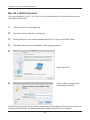
Windows 7 (WLAN AutoConfig)
With Windows 7, use WLAN AutoConfig to connect to the AirStation.
1
Click on the network icon
in the system tray.
2
Select the target AirStation’s name and click
[Connect]. If you will be connecting to this
device in the future, checking [Connect
automatically] is recommended.
- 84 -
Chapter 5 Connect to a Wireless Network
3
Enter the encryption key and click [OK].
Windows Vista (WLAN AutoConfig)
With Windows Vista, use WLAN AutoConfig to connect to the AirStation.
1
Right click on the wireless network icon
2
Click [Connect to a network].
in the system tray.
3
When the screen at left is displayed, select the
network to connect to and click [Connect].
- 85 -
Chapter 5 Connect to a Wireless Network
If the screen below is displayed, click [I want to enter the network key or passphrase instead].
Otherwise, go to step 4.
- 86 -
Chapter 5 Connect to a Wireless Network
4
Enter the encryption key and click [Connect].
Step through the wizard to finish configuration. If the Set Network Location screen is displayed,
select [Home], [Work], or [Public location] depending where you’re using the AirStation.
- 87 -
Chapter 5 Connect to a Wireless Network
Windows XP (Wireless Zero Configuration)
Windows XP includes a built-in utility to connect to your AirStation.
Note: If Client Manager 3 is installed on your computer, Wireless Zero Configuration is disabled. Uninstall Client
Manager 3 to use Wireless Zero Configuration, or just use Client Manager 3 to connect to the AirStation.
1
Right click on the wireless network icon
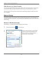
2
Click [View Available Wireless Networks].
displayed in the system tray.
3
Select the network to connect to and click
[Connect].
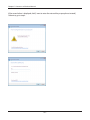
4
Enter the encryption key (twice) and click
[Connect].
Follow the instructions displayed on the screen to finish configuration.
- 88 -
Chapter 5 Connect to a Wireless Network
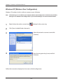
Mac OS X (Wi-Fi)
Use Wi-Fi on a Mac to connect to the AirStation.
Note:
In Mac OS X 10.6 and earlier, “Wi-Fi” appears as “AirPort”.
1
Refer to the Setup Card. Make a note of the
SSID and Key printed on the Setup Card.
2
Click the
icon in the top section of the
screen and select [Turn Wi-Fi On].
3
Find the SSID from step 1 on the list.
Click it to highlight it.
4
Enter the KEY from step 1 into the
Password entry box, check [Remember
this network], and click [Join].
It will take several seconds for configuration to complete.
- 89 -
Chapter 6 - Troubleshooting
Cannot connect to the Internet over wired connection.
• Make sure that your AirStation is plugged in!
• Check that the status LEDs of your AirStation are lit as below:
Power
Wireless
Router
Diag
LAN
Internet
Green LED on
Green LED on or flashing
Green LED may be on or off depending on your network
off
Green LED on or flashing
Green LED on or flashing
• Make sure that your computer is set to obtain an IP address automatically (see appendix C).
• Restart your AirStation.
Cannot access the web-based configuration interface.
• See chapter 4 for instructions to open the AirStation’s configuration interface.
• Enter the correct username and password to log in to the configuration interface. If you are
using AirStation with factory default settings, enter “admin” for the username and “password”
for the password.
• Verify that your web browser is not set to use proxies.
• Make sure that your computer is configured to obtain an IP address automatically (see appendix
C).
• Restart your AirStation.
- 90 -
Chapter 6 Troubleshooting
Cannot connect to the network wirelessly.
•
Configure your wireless client with the same SSID, encryption type, and encryption key as set
on the AirStation.
The factory defaults are:
SSID -
BUFFALO-XXXXXX (the last 6 digits of the AirStation’s MAC address)
Encryption Type -
WPA/WPA2 mixed mode - PSK (Connect with either WPA-PSK TKIP or WPA2-PSK AES).
Encryption Key -
Printed on the Setup Card.
Note: For details, refer to the Setup Card.
•
Place your AirStation and wireless devices 2 - 10 feet apart.
•
Restart your AirStation.
You forgot the AirStation's SSID, Encryption Key, or
Password.
Hold down the reset button on the base of your AirStation for 3 seconds to initialize its settings. All
settings, including your password, SSID, and encryption key will be initialized to their defaults.
The link speed is slower than 300 Mbps (Maximum
link speed is only 130 Mbps).
By default, the AirStation’s 300 Mbps mode is not enabled. You may enable it with the following
procedure:
1. Open the configuration utility (chapter 4).
2. Click [Wireless SSID & Channel] in Easy Setup.
3. Change the value in [300 Mbps Mode] - [Band Width] to 40 MHz and click [Apply].
If you still cannot connect at 300 Mbps, check the settings of your wireless client device.
- 91 -
Chapter 6 Troubleshooting
Other Tips
Issue:
I reset my wireless router to factory settings and forgot how to log in to the configuration utility.
Answer:
Open your browser, enter 192.168.11.1 as the browser address, and hit Enter. You will be prompted
to log in. Enter “admin” for the username and “password” for the password. Click [OK] to log in. The
option to reset your password will be available on the first page.
Issue:
How do I forward ports on my wireless router for my gaming console?
Answer:
Log in to the router's configuration utility. From the home page, go to the Internet Games/Apps
section. Enter the port that needs to be forwarded, and the IP address of the gaming console.
Issue:
How do I enable or modify security encryption settings on the wireless router?
Answer:
Log in to the configuration utility with your browser. Go to [Wireless] - [Basic]. Buffalo recommends
WPA for wireless encryption. The passphrase/key should be at least 8 characters in length.
Issue:
How do I change my wireless router's broadcasted network name (SSID)?
Answer:
Log in to the wireless router with your browser. Navigate to [Wireless] - [Basic]. Find the SSID
setting. Select [Use] and enter the new name for your network. Click [Apply]. Once the wireless
router has rebooted, you will need reconnect any wireless clients to the AirStation using the new
network name. The encryption key will still be the same.
- 92 -
Chapter 6 Troubleshooting
Issue:
What can I do if my wireless connection drops randomly or seems slow?
Answer:
There are many environmental factors that may cause this. First, ensure the issue is not range related
by moving the wireless router and the client device closer together. If the the connection drops
continue, then range is probably not the issue.
Other 2.4 GHz devices such as microwaves, other wireless networks, and 2.4 GHz wireless phones
may impact performance. Try a different wireless channel for your wireless router. Log in to the
wireless router with your browser. Click on [Wireless] - [Basic]. Wireless channels from 1 - 11 may be
selected. Try the Auto-Channel option if available. Otherwise, manually select an alternate channel
and click [Apply].
Issue:
Though I am able to successfully make a connection with my wireless router, I am unable to access
the Internet with my web browser.
Answer:
First, power off the Cable or DSL modem, the wireless router, and your computer. Move the router's
mode switch to the ON position. Verify that the modem is connected to the wireless router with an
Ethernet cable to the WAN port. Power on the modem and wait one minute. Power on the wireless
router and wait another minute. Power on the computer. Open a browser on the computer and
navigate to a familiar website to verify whether the Internet connection is functioning normally.
If after these steps, an Internet connection is still unavailable, power off the Cable or DSL modem
and computer again and directly connect your computer to the Cable or DSL modem with a cable
between the computer and the port on the modem. Power on the modem and wait one minute.
Power on the computer and again check for an Internet connection.
If an Internet connection IS NOT available with a direct connection to the computer, please call the
Internet Service Provider who installed the modem.
If an Internet connection IS available with a direct connection to the computer, please call our
customer support.
- 93 -
Chapter 6 Troubleshooting
Issue:
Where can I download the latest drivers, firmware and instructions for my Buffalo wireless products?
Answer:
The latest drivers and firmware are available online at
www.buffalotech.com
- 94 -
Chapter 7 - Default Configuration Settings
Feature
Parameter
Default Setting
Internet
Method of Acquiring IP Address
Easy Setup (Internet Connection Wizard)
Default Gateway
None
DNS Name Server Address
None
Internet MAC Address
Use default MAC address
MTU Size of Internet Port
1500 Bytes
Default PPPoE Connection
No Active Session
IP Unnumbered PPPoE
Connection
No Active Session
PPPoE Connection List
None
Preferred Connections
None
Dynamic DNS Service
Disabled
Current Dynamic DNS
Settings
None
LAN Side IP Address
192.168.11.1(255.255.255.0)
DHCP Server
Enabled
DHCP IP Address Pool
192.168.11.2 for up to 64 Address(es)
PPTP Server
Disabled
Authorization Type
MS-CHAPv2 (40/128-bit Encryption)
Server IP Address
Auto
Client IP Address
Auto
DNS Server IP Address
LAN IP address of the AirStation
WINS Server IP Address
None
MTU/MRU Value
1396
PPTP User List
None
LAN Side IP Address
Router Mode:
192.168.11.1 (255.255.255.0)
(Router Mode only)
PPPoE
(Router Mode only)
DDNS
(Router Mode only)
VPN Server
(Router Mode only)
LAN
Bridge Mode (Router Switch off ):
192.168.11.100 (255.255.255.0)
Bridge Mode (Router Switch set to Auto):
Obtain automatically from DHCP Server
- 95 -
Chapter 7 Default Configuration Settings
Feature
Parameter
Default Setting
DHCP Server
Enabled
(Router Mode only)
DHCP IP Address Pool
192.168.11.2 - 192.168.11.65
(Router Mode only)
LAN Side IP Address
(IP Unnumbered)
None
(Router Mode only)
Lease Period
48 Hours
(Router Mode only)
Default Gateway
AirStation's IP Address
(Router Mode only)
DNS Servers
AirStation's IP Address
(Router Mode only)
WINS Server
Do Not Specify
(Router Mode only)
Domain Name
Assigned Domain Name
(Router Mode only)
Default Gateway
None
(Bridge Mode only)
DNS Server Address
None
(Bridge Mode only)
DHCP
Current DHCP Clients
None
Address Translation
Enabled
Log Output of Deleted Packets
Disabled
Routing
Routing
None
WPS
WPS
Enabled
External Registrar
Enabled
AirStation PIN
An 8-digit random value
(Printed on the label of the AirStation)
WPS Security Settings
WPS status:
SSID:
(Router Mode only)
NAT
(Router Mode only)
Security:
Encryption key:
- 96 -
Configured
BUFFALO-XXXXXX (the last 6
digits of the AirStation’s MAC
address)
WPA/WPA2 mixedmode - PSK
TKIP/AES mixedmode
An 8-digit random value
(Printed on the Setup Card)
Chapter 7 Default Configuration Settings
Feature
Parameter
Default Setting
Basic
Wireless Radio
Enabled
Wireless Channel
Auto Channel
300 Mbps Mode
Band Width: 20 MHz
Extension Channel: -
Broadcast SSID
Allowed
Separate feature
Not used
SSID
BUFFALO-XXXXXX
Wireless Authentication
WPA/WPA2 mixedmode - PSK
Wireless Encryption
TKIP/AES mixedmode
WPA-PSK (Pre-Shared Key)
An 8-digit random value
(Printed on the Setup Card)
Rekey Interval
60 minutes
Multicast Rate
Auto
DTIM Period
1
Privacy Separator
Disabled
Advanced
WMM
WMM-EDCA Parameters
(Priority AC_BK (Low) )
WMM-EDCA Parameters
(Priority AC_BE (Normal) )
For AP
For STA
CWmin
15
15
CWmax
1023
1023
AIFSN
7
7
TXOP Limit
0
0
Admission Control
-----
Disabled
For AP
For STA
CWmin
15
15
CWmax
63
1023
AIFSN
3
3
TXOP Limit
0
0
Admission Control
-----
Disabled
- 97 -
Chapter 7 Default Configuration Settings
Feature
Parameter
Default Setting
WMM-EDCA Parameters
(Priority AC_VI (High) )
WMM-EDCA Parameters
(Priority AC_VO (Highest) )
MAC Filter
WDS
AOSS
For AP
For STA
CWmin
7
7
CWmax
15
15
AIFSN
1
2
TXOP Limit
94
94
Admission Control
-----
Disabled
For AP
For STA
CWmin
3
3
CWmax
7
7
AIFSN
1
2
TXOP Limit
47
47
Admission Control
-----
Disabled
Enforce MAC Filtering
Disabled
Registration List
None
WDS
Enabled
Specify Master/Slave
Master
Exclusive SSID for WEP
None
Encryption level expansion
Enabled
Dedicated WEP SSID isolation
Disabled
Allow WEP for Game Console Only
Disabled
AOSS Button on the AirStation Unit Enabled
Multicast
Control
Snooping
Enabled
Multicast Aging Time
300 Sec.
Firewall
Log Output
Disabled
Basic Rules
Prohibit NBT and Microsoft-DS routing (Router Mode only)
Reject ident requests
Block ping from Internet
IP Filter
(Router Mode only)
Log Output
Disabled
IP Filter
None
VPN Passthrough IPv6 Passthrough
(Router Mode only)
Disabled
PPPoE Passthrough
Disabled
PPTP Passthrough
Enabled
- 98 -
Disabled
Enabled
Enabled
Chapter 7 Default Configuration Settings
Feature
Parameter
Default Setting
Port Forwarding
Forwarded Ports
None
IP Address of DMZ
None
UPnP
Enabled
QoS for transmission to the
Internet
Disabled
(Router Mode only)
Name
AirStation Name
AP + AirStation's MAC Address
Network Services
Enabled
Administrator
admin (fixed)
Administrator Password
password
Local Date
2012 Year 1 Month 1 Day
Local Time
0 Hour 0 Minute 0 Seconds
Time Zone
(GMT−06:00) Central Standard Time: CST or
(GMT+00:00) Greenwich Mean Time,London
NTP Functionality
Enabled
NTP Server
time.nist.gov
Update Interval
24 hours
Log Output
Disabled
Management Access
Prohibit configuration from wireless LAN
Disabled
Prohibit configuration from wired LAN
Disabled
Permit configuration from wired Internet
Disabled
(Router Mode only)
DMZ
(Router Mode only)
UPnP
(Router Mode only)
QoS
Password
Time/Date
NTP
Access
Log
Transfer Logs
Disabled
Syslog Server
None
Logs
Router Mode:
Address Translation, IP Filter, Firewall, PPPoE Client, Dynamic DNS, DHCP Client, DHCP Server,
AOSS, Wireless Client, Authentication, Setting
Changes, System Boot, NTP Client, and Wired
Link
Bridge Mode:
IP Filter, DHCP Client, AOSS, Wireless Client, Authentication, Setting Changes, System Boot, NTP
Client, and Wired Link
- 99 -