1
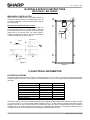
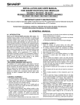
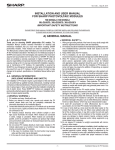
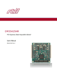
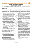
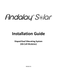
Ver. 1.0UJ Aug 25, 2008
INSTALLATION MANUAL AND USER MANUAL
FOR SHARP PHOTOVOLTAIC MODULES
ND-123UJF / ND-130UJF
PLEASE READ THIS MANUAL CAREFULLY BEFORE INSTALLING OR USING THE MODULES.
PLEASE PASS ALONG THIS MANUAL TO YOUR CUSTOMER.
A) GENERAL MANUAL
2. Install PV modules and ground frames and other metal
components in accordance with applicable codes and regulations.
3. PV modules should be installed and maintained by qualified
personnel. Only installation/service personnel should have access
to the PV module installation site.
4. When PV modules are installed on roofs or any other structures
above ground, appropriate safety practices should be followed and
appropriate safety equipment should be used in order to avoid
possible safety hazards. Note that the installation of PV modules
on some roof types may require the addition of fireproofing, as
required by local building/fire codes.
5. Roof mounted PV modules are to be mounted over a fire resistant
roof.
6. Only PV modules with the same cell size should be connected in
series.
7. Follow all safety precautions of other components used in the
system.
8. In order to avoid risk of injury or electrical shock, do not allow
anyone to handle damaged PV modules if the person is unqualified
or has limited knowledge of PV modules.
9. Avoid uneven shade on the PV module surface. Shaded cells may
become hot (“hot spot” phenomenon) which may result in
permanent damage to the module (e.g., solder joints may peel off).
10. Do not clean the glass surface with chemicals. Do not let water
stay on the glass surfaces of PV modules for a long time. This
creates a risk of permanent damage to the glass, such as white
efflorescence, otherwise known as “glass disease,” which may
cause reduced power output.
11. To avoid dirt accumulation or white efflorescence due to water
accumulation, do not install PV modules horizontally (flat).
12. Do not cover the water drain holes of the frame. There is a risk of
frost damage when the frame is filled with water.
13. In high snow load regions, appropriate measures are to be taken
so that PV module frames (on lower edges of the modules) will not
be damaged.
14. Do not expose PV modules to sunlight concentrated with mirrors,
lenses or other means.
15. Turn off inverters and circuit breakers immediately, should a
problem occur.
16. A defective PV module or module with broken glass may generate
power even if it is removed from the system. It may be dangerous
to handle the defective PV module while exposed to sunlight. Place
defective PV modules in cartons so PV cells are completely
shaded.
17. The maximum open circuit voltage must not be greater than the
specified maximum system voltage. Voltage is proportional to the
number of PV modules in series and is affected by weather
conditions. For strings connected in parallel take proper measures
to block reverse current flow.
18. Keep children away from PV modules.
A-1. INTRODUCTION
This Installation Manual contains essential information for electrical
and mechanical installation that you must know before installing
SHARP photovoltaic (PV) modules. These modules are UL listed (UL
1703). This Manual also contains safety information you need to be
familiar with. All the information described in this Manual is the
intellectual property of SHARP and is based on the technologies and
experience that have been acquired and accumulated over the long
history of SHARP. This Manual does not constitute a warranty,
expressed or implied. SHARP does not assume responsibility and
expressly disclaims liability for loss, damage, or expense arising out of
or in any way connected with installation, operation, use or
maintenance of PV modules. No responsibility is assumed by SHARP
for any infringement of patents or other rights of third parties that may
result from use of PV modules. SHARP reserves the right to make
changes to the product, specifications or Installation Manual without
prior notice.
A-2. GENERAL INFORMATION
(INCLUDING WARNING AND SAFETY)
The installation of PV modules requires a great degree of skill and
should only be performed by qualified licensed professionals, including
licensed contractors and licensed electricians. Please be aware that
there is a serious risk of various types of injury occurring during the
installation including the risk of electric shock. These SHARP PV
modules are equipped with a permanently attached junction box for
ease of installation of wires and conduit.
< GENERAL WARNING >
1. PV modules are heavy. Handle with care.
2. Before you attempt to install, wire, operate and maintain the PV
module, please make sure that you completely understand the
information described in this Installation Manual.
3. Contact with electrically active parts of a PV module such as
terminals can result in burns, sparks and lethal shock whether the
PV modules are connected or not.
4. PV modules produce electricity when sufficient sunlight or other
light source illuminates the module. When modules are connected
in series, voltage is cumulative. When modules are connected in
parallel, current is cumulative. PV systems can produce high
voltage and current which could present an increased hazard and
may cause serious injury or death.
5. Do not connect PV modules directly to motor loads. Variation in PV
module output power as a function of solar irradiance may damage
directly-connected loads. For example,
1: In the case of a brushless motor, the lock function may become
active and the motor may be damaged;
2: In the case of a brush type motor, the coil may be damaged.
< GENERAL SAFETY >
1. Consult local codes and applicable laws concerning required
permits and regulations concerning installation and inspection
requirements.
-1-
Installation Manual for PV modules
Ver. 1.0UJ Aug 25, 2008
disconnected from the system.
12. Do not unplug a connector if the system circuit is connected to an
operating load.
13. Do not work alone (always work as a team of 2 or more people).
14. Wear a safety harness when working above the ground.
15. Do not wear metallic jewelry which may conduct electricity and
enable electric shock during installation.
16. Do not damage the back sheet of PV modules when fastening the
PV modules to a support by bolts.
17. Do not damage the surrounding PV modules or mounting structure
when replacing a PV module.
18. Use UV resistant materials, wire management hardware to secure
cables. Drooping cables may cause various problems, such as
electricity leakage.
19. Take proper measures for preventing the laminate (consisting of
encapsulant, cells, glass, back sheet, etc.) from dropping out of the
frame in case the glass is broken.
20. Cables shall be located so that they will not be exposed to direct
sunlight in order to prevent degradation of cables.
< HANDLING SAFETY >
1. Do not expose the PV module to excessive loads on the surface of
the PV module or twist the frame. The glass may break.
2. Do not stand or step on the PV module. The glass may be slippery,
and there is a risk of injury or electric shock if glass is broken.
3. Do not hit or put excessive load on the glass or back film. PV cells
may break.
4. To avoid damage to the back sheet, do not scratch or hit the back
sheet.
5. To avoid damage to the junction box, do not hit the junction box; do
not pull the cables.
6. Never touch the end of output cables with bare hands when the
module is illuminated. Cover the surface of module with cloth or
other sufficiently opaque material to block the module from incident
light and handle the wires with insulated gloved hands to avoid
electric shock.
7. Do not scratch the output cable or bend it with force. The insulation
of the output cable may break which may result in electricity
leakage or shock.
8. Do not pull the output cable excessively. The output cable
connection may become loose and cause electricity leakage or
shock.
9. Do not drill holes in the frame. It may compromise the frame
strength and cause corrosion of the frame.
10. Do not scratch the insulation coating of the frame (except for
grounding connection). It may cause corrosion of the frame or
compromise the frame strength.
11. Do not loosen or remove the screws from the PV module. It may
compromise the strength of the PV module and cause corrosion.
12. Do not touch the PV module with bare hands. The frame of the PV
module has sharp edges and may cause injury. Wear suitable
gloves, such as leather gloves with padding in the palm and finger
areas.
13. Do not drop the PV module or allow objects to fall on the PV
module.
14. Do not lift the PV module by only one side. The frame may bend.
Always use two hands to lift and carry the PV module on the long
side of the frame.
15. Some PV modules incorporate one or more support bars on the
back of the module. Do not mount or carry the PV module using
the support bar(s) on the back of the module.
A-3. PV MODULE COMPONENTS
A-4. SITE SELECTION
PV modules should be installed in a location where there is no shading
throughout the year. In the northern hemisphere, PV modules should
typically face south, and in the southern hemisphere, PV modules
should typically face north.
Please make sure that there are no obstructions in the surroundings of
the site of installation. Take proper steps in order to maintain reliability
and safety in case the PV modules are installed in areas that have
heavy snow / extreme cold / strong winds / installations over, or near,
water and areas where installations are prone to salt water exposure or
on small islands or in desert areas. If you are planning to use the PV
modules where salt water damage may occur, please consult with
SHARP to determine an appropriate installation method, or if
installation is possible.
< INSTALLATION SAFETY >
1. Always wear protective head gear, insulating gloves and safety
shoes (with rubber soles).
2. Keep the PV module packed in the carton until installation.
3. Do not touch the PV module unnecessarily during installation. The
glass surface and the frame may be hot. There is a risk of burns
and electric shock.
4. Do not work in rain, snow or windy conditions.
5. Use insulated tools.
6. Do not use wet tools.
7. When installing PV modules, do not drop any objects (e.g., PV
modules or tools).
8. Make sure flammable gases are not generated or present near the
installation site.
9. Terminate module-to-module wires in the junction box fully and
correctly. Check all connections.
10. Due to the risk of electrical shock, do not perform any work if the
terminals of the PV module are wet.
11. Do not touch the junction box and the end of the output cables
(connectors) with bare hands during installation or under sunlight,
regardless of whether the PV module is connected to or
-2-
Installation Manual for PV modules
Ver. 1.0UJ Aug 25, 2008
mounting hole or hardware that is used for structurally mounting the
module. UL 1703 prohibits the use of a bonding fastener for any
purpose other than ground bonding.
A-5. TILT ANGLE SELECTION
The tilt angle of the PV module is measured between the surface of the
PV module and a horizontal ground surface. The PV module generates
maximum output power when it faces the sun directly.
For standalone systems with batteries where the PV modules are
attached to a permanent structure, the tilt angle of the PV modules
should be selected to optimize the performance based on seasonal
load and sunlight. In general, if the PV output is adequate when
irradiance is low (e.g., winter), then the angle chosen should be
adequate during the rest of the year. For grid-connected installations
where the PV modules are attached to a permanent structure, PV
modules should be tilted so that the energy production from the PV
modules will be maximized on an annual basis.
A-7. MAINTENANCE
SHARP PV modules are designed for long life and require very little
maintenance. If the angle of the PV module is 5 degrees or more,
normal rainfall is usually sufficient to keep the module glass surface
clean under most weather conditions. If dirt build-up becomes
excessive, clean the glass surface only with a soft cloth using water. If
cleaning the back of the module is required, take utmost care not to
damage the back side materials. In order to ensure proper operation of
the system, please check all wiring connections and the condition of
the wire insulation periodically.
A-6. ELECTRICAL INSTALLATION
To ensure proper system operation and maintain the warranty, be
careful to observe the correct cable connection polarity (Figure 1) when
connecting the modules to a battery or to other modules. If not
connected correctly, the bypass diode(s) could be destroyed. All PV
modules must be grounded by electrical connection of the module
frames to ground. Care must be taken to arrange the system ground so
that the removal of one module from the circuit will not interrupt the
grounding of any of the other modules. For grounding, each PV module
has a hole in the frame for either a bolt, nut and washer, a ground lug
fastened by bolt or screw, or an appropriate screw (hardware not
provided). Installation for wiring shall be in accordance with the NEC
and grounding method shall comply with the NEC, article 250 and the
relevant instructions below. In a connection of this type, the hardware
(such as a star washer) must score the frame surface to make positive
electrical contact with the frame. The ground wire must not be smaller
than No.14 AWG (2.1 mm2), and should be sized according to the
NEC.
Hardware used must be compatible with the mounting structure
material to avoid galvanic corrosion.
The module junction box is shown in Figure 2. When connecting the
modules to a battery or to other modules, you must carefully observe
correct cable connection polarity as shown Figures 1 and 4. If not
connected correctly, the bypass diodes could be destroyed. This will
void your warranty.
Open the cover of the junction box by loosening the two cover screws
as shown in Figure 2.
Figure 3 shows the inside of the junction box. Typical terminal cabling
is AWG 14, but will be dependent upon system design as guided by the
National Electrical Code. Remove the appropriate grommets and route
the interconnecting cables through grommets as shown in Figure 3. To
remove the grommets, push them from inside of the box.
To connect wires to the terminal block, a wire lug connector may be
used as shown in Figure 6. For direct wiring, strip back insulation about
16mm (5/8”) and wrap stripped wire around screw under square
washer as shown in Figure 7. Tighten terminal screw securely with a
proper screwdriver. After completed terminal wiring, secure the cover of
the junction box.
SERIES WIRING (VOLTAGE ADDITIVE)
+
-
+
-
+
-
+
PARALLEL WIRING (CURRENT ADDITIVE)
+
-
+
-
+
-
+
Figure 1
Grounding Using Existing Ground Hole (Figure 8)
The existing ground holes can be used with stainless steel #10-32
bolts, #10 lock washers and #10-32 nuts. All grounding hardware must
have a thread count of at least 32 turns per inch. These holes may be
used to secure an outdoor-rated, tinned copper, UL listed lay in ground
lug such as Ilsco model GBL4-DBT or equivalent.
Grounding Using Existing Unused Module Mounting Hole
(Figure 9)
An existing otherwise unused module mounting hole can be used to
install the same grounding hardware noted above. Do not use a
Loosen the two cover screws to open the cover
Figure 2
-3-
Installation Manual for PV modules
Ver. 1.0UJ Aug 25, 2008
Figure 6
Remove the appropriate grommets. (Push them from inside of the box)
Figure 3
Figure 7
1
2
3
1
2 : Negative Terminal
3
4 : Positive Terminal
4
Lay in Ground Lug
Figure 8
Figure 4
Figure 9
Figure 5
-4-
Installation Manual for PV modules
Ver. 1.0UJ Aug 25, 2008
B) MODULE SPECIFIC INSTRUCTIONS
ND-123UJF / ND-130UJF
MECHANICAL INSTALLATION
D
Please review the descriptions below and drawings carefully; not
mounting the modules according to the described method may void
your warranty. Additionally, UL has tested and listed these modules for
mounting using bolts.
D
C
Mounting Using Frame Bolt Holes (Figure 10 & 11)
The modules may be fastened to a support using the bolt holes in the
bottom of the frame at location “C”, as shown in Figure 11 (back view
of the module) and Figure 10 (mounting detail). The module should be
fastened with four (4) M8 (5/16”) bolts. The mounting method is
designed to withstand loads of 2400 Pa. Take care during installation
to not block the drain holes (D) shown in Figure 11.
C
D
SOLAR MODULE
WASHER
BOLT
mm
BOLTM8
M8XX20
20mm
C
WASHER
SPRING WASHER
NUT
C
D
Figure 10
Figure 11
D
C) ELECTRICAL INFORMATION
ELECTRICAL RATINGS
Rated electrical characteristics are within ±10 percent of the indicated values of Isc, Voc and within +10/-5 percent of Pmax under Standard Test
Conditions (irradiance of 100 mW/cm2, AM 1.5 spectrum, and a cell temperature of 25˚C (77˚F)). The warranty conditions are specified elsewhere in
this manual.
Maximum Power (Pmax)
Open-Circuit Voltage (Voc)
Short-Circuit Current (Isc)
Voltage at maximum power (Vpmax)
Current at maximum power (Ipmax)
Maximum System Voltage
Minimum Blocking diode
Maximum Series Fuse
ND-123UJF
123.0 W
21.78 V
7.99 A
17.21 V
7.15 A
600 V
15 A
15 A
ND-130UJF
130.0 W
21.90 V
8.20 A
17.40 V
7.50 A
600 V
15 A
15 A
Under normal conditions, a PV module may produce more current and/or voltage than reported at Standard Test Conditions. Accordingly, the values
of Isc and Voc marked on UL 1703 listed modules should be multiplied by a factor of 1.25 when determining component voltage ratings, conductor
ampacities, fuse sizes and size of controls connected to the module output. Refer to Sec. 690-8 of the National Electric Code for an additional
multiplying factor of 125 percent (80 percent de-rating) which may be applicable. Where Canadian UL listing applies, installation shall be in
accordance with CSA C22.1, Safety Standard for Electrical Installations, Canadian Electrical Code, Part 1.
-5-
Installation Manual for PV modules
Ver. 1.0UJ Aug 25, 2008
SHARP ELECTRONICS CORPORATION
PHOTOVOLTAIC MODULE LIMITED WARRANTY
This Limited Warranty applies to photovoltaic modules manufactured by SHARP with the following model numbers:
ND-123UJF/ND-130UJF.
Limited Warranty For Materials or Workmanship: Sharp Electronics Corporation warrants to the first consumer purchaser
that this Sharp brand product (the “Product”), when shipped in its original container, will be free from defective
workmanship and materials, and Sharp agrees that for a period of one (1) year from the date of purchase by the consumer,
that Sharp will, at its option, either repair the defect or replace the defective Product or part thereof with a new or
remanufactured equivalent at no charge to the purchaser for parts or labor for the period(s) set forth below.
Limited Warranty For Power: The warranty period with respect to power output continues for a total of 25 years from date
of purchase by the consumer, the first 10 years at 90% minimum rated power output and the balance of 15 years at 80%
minimum rated power output. This warranty is transferable when product remains installed in original location at the time
of product warranty registration.
This warranty does not apply to any alteration of the appearance of the Product that does not affect the performance or
functionality of the Product, nor to the additional excluded item(s) set forth below nor to any Product, in Sharp’s sole
discretion, the exterior of which has been damaged or defaced, which has been subjected to misuse, abnormal service or
handling, or which has been altered or modified in design or construction.
In order to enforce the rights under this limited warranty, the purchaser should follow the steps set forth below and provide
proof of purchase to the servicer.
The limited warranty described herein is in addition to whatever implied warranties may be granted to purchasers by law.
ALL IMPLIED WARRANTIES INCLUDING THE WARRANTIES OF MERCHANTABILITY AND FITNESS FOR USE ARE
LIMITED TO THE PERIOD(S) FROM THE DATE OF THE PURCHASE SET FORTH BELOW. Some states do not allow
limitations on how long an implied warranty lasts, so the above limitation may not apply to you.
Neither the sales personnel of the seller nor any other person is authorized to make any warranties other than those
described herein, or to extend the duration of any warranties beyond the time period described above on behalf of Sharp.
The warranties described herein shall be the sole and exclusive warranties granted by Sharp and shall be the sole and
exclusive remedy available to the purchaser. Correction of defects, in the manner and for the period of time described
herein, shall constitute complete fulfillment of all liabilities and responsibilities of Sharp to the purchaser with respect to the
Product and shall constitute full satisfaction of all claims, whether based on contract, negligence, strict liability or otherwise.
In no event shall Sharp be liable, or in any way responsible, for any damages or defects in the Product which were caused
by repairs or attempted repairs performed by anyone other than an authorized servicer. Nor shall Sharp be liable or in any
way responsible for any incidental or consequential economic, property or special damage. Some states do not allow the
exclusion of incidental or consequential damages, so the above exclusion may not apply to you.
THIS WARRANTY GIVES YOU SPECIFIC LEGAL RIGHTS. YOU MAY ALSO HAVE OTHER RIGHTS, WHICH VARY
FROM STATE TO STATE.
SHARP ELECTRONICS CORPORATION
Sharp Plaza, Mahwah, New Jersey 07495-1163
-6-
Installation Manual for PV modules
Ver. 1.0UJ Aug 25, 2008
Additional Item(s) Excluded from Warranty Coverage
Warranty coverage does not apply when:
a) the product is installed or repaired or serviced in a manner that is contrary to Sharp’s Installation Manual;
b) the product is installed in a mobile or marine environment, subjected to improper voltage or power surges or
abnormal environmental conditions (such as acid rain or other pollution);
c) the components in the construction base on which the module is mounted are defective;
d) external corrosion, mold discoloration or the like occurs;
e) the product has been moved from its original installation;
f) the model number or serial number of the product is altered, removed or rendered illegible.
Sharp’s aggregate liability in connection with the Product, if any, shall not exceed the purchase price paid to Sharp for the
Product or service which gave rise to the claim under the Limited Warranty.
The repair, replacement of the Product, or the supply of additional Product does not cause the beginning of new warranty
terms, nor shall the original warranty terms of this Limited Warranty be extended. Any replaced product shall become
Sharp’s property
Where to Obtain Service:
Warranty service is available at a Sharp Authorized
Dealer located in the United States. To find the location of
the nearest Sharp Authorized Dealer, call Sharp toll free
at 1-800 SOLAR06 (800-765-2706).
Call toll free at 1-800-765-2706 to obtain a Return
Authorization Number and shipping instructions. Proof of
Purchase will be required.
What to do to Obtain Service:
Ship prepaid or carry in your Product to a Sharp
Authorized Dealer. Be sure to have Proof of Purchase
available. If you ship the Product, be sure it is insured and
packaged securely. Sharp will not be responsible for the
costs of de-installation or reinstallation.
SHARP ELECTRONICS CORPORATION
Sharp Plaza, Mahwah, New Jersey 07495-1163
-7-
Installation Manual for PV modules