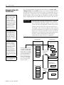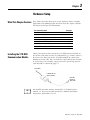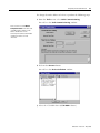
1
ControlLogix DeviceNet Interface Module 1756-DNB User Manual Important User Information Because of the variety of uses for the products described in this publication, those responsible for the application and use of this control equipment must satisfy themselves that all necessary steps have been taken to assure that each application and use meets all performance and safety requirements, including any applicable laws, regulations, codes and standards. The illustrations, charts, sample programs and layout examples shown in this guide are intended solely for purposes of example. Since there are many variables and requirements associated with any particular installation, Allen-Bradley does not assume responsibility or liability (to include intellectual property liability) for actual use based upon the examples shown in this publication. Allen-Bradley publication SGI-1.1, Safety Guidelines for the Application, Installation and Maintenance of Solid-State Control (available from your local Allen-Bradley office), describes some important differences between solid-state equipment and electromechanical devices that should be taken into consideration when applying products such as those described in this publication. Reproduction of the contents of this copyrighted publication, in whole or part, without written permission of Rockwell Automation, is prohibited. Throughout this manual we use notes to make you aware of safety considerations: ATTENTION ! Identifies information about practices or circumstances that can lead to personal injury or death, property damage or economic loss. Attention statements help you to: • identify a hazard • avoid a hazard • recognize the consequences IMPORTANT Identifies information that is critical for successful application and understanding of the product. Allen-Bradley, ControlLogix, and Data Highway Plus are trademarks of Rockwell Automation. ControlNet is a trademark of ControlNet International, Ltd. DeviceNet is a trademark of Open DeviceNet Vendor Association, Inc. Ethernet is a trademark of Digital Equipment Corporation, Intel, and Xerox Corporation. RSLinx, RSLogix 5000, and RSNetWorx are trademarks of Rockwell Software. Windows 95/98 and Windows NT are trademarks of Microsoft Corporation. European Communities (EC) Directive Compliance If this product has the CE mark it is approved for installation within the European Union and EEA regions. It has been designed and tested to meet the following directives. EMC Directive This product is tested to meet the Council Directive 89/336/EC Electromagnetic Compatibility (EMC) by applying the following standards, in whole or in part, documented in a technical construction file: • EN 50081-2 EMC — Generic Emission Standard, Part 2 — Industrial Environment • EN 50082-2 EMC — Generic Immunity Standard, Part 2 — Industrial Environment This product is intended for use in an industrial environment. Low Voltage Directive This product is tested to meet Council Directive 73/23/EEC Low Voltage, by applying the safety requirements of EN 61131-2 Programmable Controllers, Part 2 - Equipment Requirements and Tests. For specific information required by EN 61131-2, see the appropriate sections in this publication, as well as the Allen-Bradley publication Industrial Automation Wiring and Grounding Guidelines For Noise Immunity, publication 1770-4.1. This equipment is classified as open equipment and must be mounted in an enclosure during operation to provide safety protection. Preface About This User Manual Introduction This user manual is designed to provide you enough information to get a small example application up and running. Use this manual if you are knowledgeable about DeviceNet and ControlLogix products, but may not have used the products in conjunction. The information provided is a base; modify or expand the examples to suit your particular needs. The manual contains instructions on configuring a DeviceNet network using RSLinx and RSNetWorx for DeviceNet software over various networks: • • • • directly over the DeviceNet network from a ControlNet network from an Ethernet network from a Data Highway Plus network The example application demonstrates how to perform control on a DeviceNet network using a Logix5550 controller and the 1756-DNB module. You use RSLogix 5000 programming software to create a ladder logic program to control a photoeye and a RediSTATION. IMPORTANT 1 This User Manual should be used in conjunction with the 1756-DNB DeviceNet Scanner Module Installation Instructions, publication 1756-5.66. The Installation Instructions contain important information on configuring your scanner. Publication 1756-6.5.19 - May 2000 P-2 About This User Manual Contents This user manual contains the following chapters: 1 4 Before You Begin go to Chapter 1 2 Planning Your Configuration go to Chapter 2 3 5 Configuring DeviceNet From Another Network go to Chapter 5 Setting Up the Hardware go to Chapter 3 6 7 Audience Configuring the DeviceNet Network go to Chapter 4 Creating and Running the Application Program go to Chapter 6 Troubleshooting go to Chapter 7 This manual is intended for control engineers and technicians who are installing, programming, and maintaining a control system that includes a Logix5550 controller communicating on a DeviceNet network through a 1756-DNB module. We assume that you: • are developing a DeviceNet network using a ControlLogix chassis in conjunction with a 1756–DNB interface module • know each of your device’s I/O parameters and requirements • are experienced with the Microsoft® Windows environment • are familiar with RSNetWorx for DeviceNet software Publication 1756-6.5.19 - May 2000 About This User Manual The Example Application P-3 This manual describes how to set up an example application. The manual provides examples of each step of the setup, with references to other manuals for more details. System Components We used the following devices and software for the example application. For your own application, substitute your own devices to fit your needs. The recommended configurations in this user manual will help you set up the test system and get it working. Your eventual configuration will depend on your application. Note: If you use different software or fimware versions of these products some of your screens may appear slightly different from those shown in the example. Product Name Catalog Number Series Revision 1756-A4, -A7, -A10 - - Qty Hardware 1 ControlLogix chassis 1 Logix5550 controller 1756-L1 A 5.12 1 ControlLogix DeviceNet Interface module 1756-DNB A 3.003 1 DeviceNet Quad-Tap 1492-DN3TW - - 1 RediSTATION operator interface module 2705-T3DN1A42A - - 1 Series 9000 Photoeye 42GNP-9000 or equivalent - - 1 DeviceNet PC serial communication module 1770-KFD A 1.04 1 RS-232 cable 1787-RSCABL/A (PC to 1770-KFD) - - 1 24V Power Supply Regulated 24VDC, 8A - - 1 PC IBM-compatible Windows NT 4.0 - - DeviceNet dropline or trunkline cables, as needed 1787-PCABL, -TCABL, -MCABL - - 1(1) ControlLogix ControlNet Interface module 1756-CNB B 2.24 1(2) ControlLogix Data Highway Plus Interface module 1756-DHRIO B 2.17 1(3) ControlLogix Ethernet Interface module 1756-ENET A 1.18 Software RSLogix 5000 9324-RL5300END - 2.51 RSNetWorx for DeviceNet 9357-DNETL3, - 2.11 RSLinx 9355-WAB - 2.10 (1) Required if interfacing the DeviceNet network and a ControlNet network. See chapters 5 and 6. (2) Required if interfacing the DeviceNet network and a Data Highway Plus network. See chapters 5 and 6. (3) Required if interfacing the DeviceNet network and an Ethernet network. See chapters 5 and 6. Publication 1756-6.5.19 - May 2000 P-4 About This User Manual Common Techniques Used in This Manual The following conventions are used throughout this manual: • Bulleted lists provide information, not procedural steps. • Numbered lists provide sequential steps. • Information in bold contained within text identifies menu windows, or screen options, screen names and areas of the screen, such as dialog boxes, status bars, radio buttons and parameters. This symbol identifies helpful tips. TIP This is a definition box. When a word is bold within the text of a paragraph, a definition box will appear in the left margin to further define the text. A definition box defines terms that may be unfamiliar to you. Screen captures are pictures of the software’s actual screens. The names of screen buttons and fields are often in bold in the text of a procedure. Pictures of keys represent the actual keys you press. More Publication 1756-6.5.19 - May 2000 The “MORE” icon is placed beside any paragraph that references sources of additional information outside of this document. About This User Manual Where to Find More Information More For information about P-5 Refer to the following publications as needed for additional help when setting up and using your DeviceNet network: See this publication Publication Number the ControlLogix DeviceNet interface module ControlLogix DeviceNet Scanner Module Installation Instructions 1756-5.66 the ControlLogix Chassis ControlLogix Chassis Installation Instructions 1756-5.2 ControlLogix power supplies ControlLogix Power Supplies Installation Instructions 1756-5.1 connecting the DeviceNet network DeviceNet Cable Planning and Installation Manual DN-6.7.2 the 1770-KFD communication module DeviceNet RS-232 Interface Module Installation Instructions 1770-5.6 the Logix5550 controller Logix5550 Controller User Manual 1756-6.5.12 the RediSTATION RediSTATION Operator Interface User Manual 2705-804 the ControlLogix ControlNet Interface module ControlLogix ControlNet Bridge Installation Instructions 1756-5.32 the ControlLogix DH+ Interface module ControlLogix DHRIO Module Installation Instructions 1756-5.4 the ControlLogix Ethernet Interface module ControlLogix Ethernet Module Installation Instructions 1756-5.3 RSLogix 5000 software Getting Results with RSLogix 5000 9399-RLD300GR RSLinx software RSLinx Lite User Guide 9399-WAB32LUG RSNetWorx for DeviceNet software See the software’s online Help N/A terms and definitions Allen-Bradley Industrial Automation Glossary AG-7.1 TIP Many of the above publications are available online from the Automation Bookstore: http://www.theautomationbookstore.com. TIP For more information about Rockwell Software products, visit the Rockwell Software internet site: http://www.software.rockwell.com. Publication 1756-6.5.19 - May 2000 P-6 About This User Manual Terminology Publication 1756-6.5.19 - May 2000 This term Means Bridge The interface module’s support of explicit message transfer. Change of State A type of I/O data communication. The interface module can send and receive data with slave devices that have the change of state feature. Data is sent whenever a data change occurs. Data is updated at the rate of the heartbeat. Communication The 1756-DNB interface module or the 1770-KFD module. Module Cyclic A type of I/O data communication. The interface module can send and receive data with slave devices that have the cyclic feature. Data is only sent at a user-configurable rate. EDS Electronic Data Sheet. A vendor-supplied template that specifies how information is displayed as well as what is an appropriate entry (value). Explicit A type of messaging used for lower priority tasks, such as configuration Messaging and data monitoring. Heartbeat Rate Devices that are configured for change of state data can also send a “heartbeat” signal to indicate proper operation. Host Platform The computer that hosts the 1756-DNB interface module. I/O An abbreviation for “input and output”. Implicit The type of messaging used for high priority I/O control data; e.g., change Messaging of state, cyclic, polled, or strobed. Input Data Data produced by a DeviceNet device and collected by the interface module for a host platform to read. MAC ID The network address of a DeviceNet node. Network The DeviceNet network or the RSNetWorx for DeviceNet software representation of the network. Node Hardware that is assigned a single address on the network (also referred to as device). Offline When the PC communication interface is not communicating on the network. Online When the PC communication interface is configured and enabled to communicate on the network. Output Data Data produced by a host platform that is written to the interface module’s memory. This data is sent by the interface module to DeviceNet devices. PC Abbreviation for an IBM® compatible personal-computer. Polled A type of input/output-data communication. A polled message solicits a response from a single, specified device on the network (a point-to-point transfer of data). Record The node address and channel-specific memory assigned in the interface module’s non-volatile storage for a node in the scanlist. Rx An abbreviation for “receive”. Scanlist The list of devices (nodes) with which the scanner is configured to exchange I/O data. Scanner The function of the 1756-DNB interface module to support the exchange of I/O with slave modules. Slave Mode The interface module is in slave mode when it is placed in another interface module’s scanlist as a slave device. Strobed A type of I/O data communication. A strobed message solicits a response from each strobed device (a multicast transfer). It is a 64-bit message that contains one bit for each device on the network. Tx An abbreviation for “transmit”. About This User Manual Rockwell Automation Support P-7 Rockwell Automation offers support services worldwide, with over 75 sales/support offices, 512 authorized distributors, and 260 authorized systems integrators located throughout the United States alone, plus Rockwell Automation representatives in every major country in the world. Local Product Support Contact your local Rockwell Automation representative for: • • • • sales and order support product technical training warranty support support service agreements Technical Product Assistance If you need to contact Rockwell Automation for technical assistance, call your local Rockwell Automation representative, or call Rockwell directly at: 1 440 646-6800. For presales support, call 1 440 646-3NET. You can obtain technical assistance online from the following Rockwell Automation WEB sites: • www.ab.com/mem/technotes/kbhome.html (knowledge base) • www.ab.com/networks/eds (electronic data sheets) Your Questions or Comments about This Manual If you find a problem with this manual, please notify us of it on the enclosed Publication Problem Report (at the back of this manual). If you have any suggestions about how we can make this manual more useful to you, please contact us at the following address: Rockwell Automation, Allen-Bradley Company, Inc. Control and Information Group Technical Communication 1 Allen-Bradley Drive Mayfield Heights, OH 44124-6118 Publication 1756-6.5.19 - May 2000 P-8 About This User Manual Publication 1756-6.5.19 - May 2000 Table of Contents Chapter 1 Before You Begin What This Chapter Contains . . . . . . . . . . . . . . . . . . . . . What You Need to Know . . . . . . . . . . . . . . . . . . . . . . . What Your 1756-DNB Module Does. . . . . . . . . . . . . . . . Communicating with Your Devices . . . . . . . . . . . . . . . . What 1756-DNB Module Data Tables Are and What They Do . . . . . . . . . . . . . . . . . . . . . . . . . . . . The Scanner Configuration Table (SCT) . . . . . . . . . . The Scanlist Table (SLT). . . . . . . . . . . . . . . . . . . . . . RSNetWorx Software as a Configuration Tool . . . . . . . . . RSNetWorx for DeviceNet Configuration Screen Map. What’s Next? . . . . . . . . . . . . . . . . . . . . . . . . . . . . . . . . . . . . . . . . . 1-1 1-1 1-2 1-4 . . . . . . . . . . . . 1-5 1-5 1-6 1-6 1-7 1-8 . . . . . . . . . . . . . . . . . . . . 2-1 2-1 2-2 2-2 2-4 2-5 2-6 2-7 2-8 2-8 What This Chapter Contains . . . . . . . . . . . . . . . . . . . . . . . Installing the 1770-KFD Communication Module . . . . . . . . Installing the Logix5550 Controller. . . . . . . . . . . . . . . . . . . Installing the 1756-DNB Interface Module . . . . . . . . . . . . . Installing a ControlNet, Ethernet, or DH+ Interface Module. Installing the RediSTATION Operator Interface. . . . . . . . . . Installing the Series 9000 Photoeye . . . . . . . . . . . . . . . . . . How Your Example System Will Look . . . . . . . . . . . . . . . . What’s Next? . . . . . . . . . . . . . . . . . . . . . . . . . . . . . . . . . . . 3-1 3-1 3-2 3-2 3-3 3-5 3-6 3-7 3-7 Chapter 2 Planning Your Configuration and Data Mapping Your Devices What You Need to Know . . . . . . . . . . . . . . . . . . . Beginning the Process . . . . . . . . . . . . . . . . . . . . . . The Example Network. . . . . . . . . . . . . . . . . . . . . . Example Network Devices . . . . . . . . . . . . . . . . RediSTATION Operator Interface Data Mapping RediSTATION Input Data Mapping Example . . . RediSTATION Output Data Mapping Example. . Photoeye Input Data Mapping . . . . . . . . . . . . . Photoeye Input Data Mapping Example . . . . . . What’s Next? . . . . . . . . . . . . . . . . . . . . . . . . . . . . . . . . . . . . . . . . . . . . . . . . . . . . . . . . . . . . . . . . . . . . . Chapter 3 Hardware Setup Chapter 4 Configuring the DeviceNet Network i What This Chapter Contains . . . . . . . . . . . . . . . Installing the Software. . . . . . . . . . . . . . . . . . . . Using RSLinx to Configure the DeviceNet Driver Using RSNetWorx to Configure the 1756-DNB Module Scanlist. . . . . . . . . . . . . . Setting Up an Online Connection . . . . . . . . . Setting the 1756-DNB Node Address . . . . . . . Configuring the Scanlist . . . . . . . . . . . . . . . . . . . . . . . . 4-1 . . . . . . . . 4-1 . . . . . . . . 4-2 . . . . . . . . . . . . . . . . . . . . . . . . . . . . . . . . 4-4 4-4 4-6 4-9 Publication 1756-6.5.19 - May 2000 Table of Contents ii Chapter 4 (continued) Verifying the Photoeye Configuration . . . . . . . . . . . . . . . 4-12 Verifying the RediSTATION Configuration . . . . . . . . . . . 4-14 AutoMapping the Devices into the Scanlist . . . . . . . . . . . 4-15 Saving the DeviceNet Configuration . . . . . . . . . . . . . . . 4-18 What’s Next? . . . . . . . . . . . . . . . . . . . . . . . . . . . . . . . . . . . 4-18 Chapter 5 Configuring DeviceNet From Another Network What This Chapter Contains . . . . . . . . . . . . . . . . . . . . . . . 5-1 Where to Find More Information . . . . . . . . . . . . . . . . . . . . 5-2 Configuring DeviceNet from a ControlNet Network . . . . . . 5-2 Configuring DeviceNet from an Ethernet Network . . . . . . . 5-5 Configuring DeviceNet From a Data Highway Plus Network 5-8 What’s Next? . . . . . . . . . . . . . . . . . . . . . . . . . . . . . . . . . . . 5-10 Chapter 6 The Example Application Program What This Chapter Contains . . . . . . . . . . . . Installing the Software. . . . . . . . . . . . . . . . . Creating the Example Application . . . . . . . . Creating a New Controller . . . . . . . . . . . Creating the Controller Tags . . . . . . . . . . I/O Configuration . . . . . . . . . . . . . . . . . Creating the Ladder Logic. . . . . . . . . . . . Downloading and Running the Example Application Program . . . . . . . . . . . . . . . . . Downloading and Running the Program from a ControlNet Network . . . . . . . . . . Downloading and Running the Program from an Ethernet Network . . . . . . . . . . . Downloading and Running the Program from a DH+ Network . . . . . . . . . . . . . . . What’s Next? . . . . . . . . . . . . . . . . . . . . . . . . . . . . . . . . . . . . . . . . . . . . . . . . . . . . . . . . . . . . . . . . . . . . . . . . . . . . . . . . . . . . . . . . . . . . . . . . . . . . . 6-1 6-2 6-2 6-2 6-3 6-5 6-7 . . . . . . . . . . . 6-9 . . . . . . . . . . . 6-9 . . . . . . . . . . . 6-11 . . . . . . . . . . . 6-13 . . . . . . . . . . . 6-14 Chapter 7 Troubleshooting What This Chapter Contains . . . . . . . . . . . . Power-Up Cycle Diagnostics . . . . . . . . . . . . Node Address/Status Indicator . . . . . . . . . . . Interpreting the Three LED Status Indicators. MOD/NET Status Indicator . . . . . . . . . . . IO Status Indicator . . . . . . . . . . . . . . . . . OK Status Indicator . . . . . . . . . . . . . . . . . . . . . . . . . . . . . . . . . . . . . . . . . . . . . . . . . . . . . . . . . . . . . . . . . . . . . . . . . . . . . . . . . . . . . . . . . . . . . 7-1 7-1 7-2 7-4 7-4 7-5 7-6 Appendix A 1756-DNB Status Structure Index Publication 1756-6.5.19 - May 2000 Module Status Structure . . . . . . . . . . . . . . . . . . . . . . . . . . . A-1 Chapter 1 Before You Begin What This Chapter Contains This chapter provides an overview of communication between a Logix5550 controller and DeviceNet devices via a 1756-DNB module. The data tables and the RSNetWorx for DeviceNet screens and windows used to configure data tables are also described. The following table identifies what this chapter contains and where to find specific information. What You Need to Know For information about See page What You Need to Know 1-1 What Your 1756-DNB Module Does 1-2 Communicating with Your Devices 1-4 What 1756-DNB Module Data Tables Are and What They Do 1-5 The Scanner Configuration Table (SCT) 1-5 The Scanlist Table (SLT) 1-6 RSNetWorx Software as a Configuration Tool 1-6 RSNetWorx for DeviceNet Configuration Screen Map 1-7 Before configuring your 1756-DNB module, you must understand: • the data exchange between the controller and DeviceNet devices through the 1756-DNB module • user-configurable 1756-DNB module data tables • the role of RSNetWorx for DeviceNet software 1 Publication 1756-6.5.19 - May 2000 1-2 Before You Begin What Your 1756-DNB Module Does In a typical configuration, the 1756-DNB module acts as an interface between DeviceNet devices and the Logix5550 controller. DeviceNet Network ControlLogix Chassis Logix5550 Controller 1770-KFD Interface Module 1756-DNB Module Series 9000 Photoeye PC with RSNetWorx for DeviceNet software FLEX I/O Rack RediSTATION DeviceNet Devices 1305 Drive The 1756-DNB module communicates with DeviceNet devices over the network to: • read inputs from a device • write outputs to a device • download configuration data • monitor a device’s operational status The 1756-DNB module communicates with the controller in the form of Input, Output, and Diagnostic Tables. Information exchanged includes: • device I/O data • status information • configuration data Publication 1756-6.5.19 - May 2000 Before You Begin 1-3 A controller to I/O DeviceNet configuration is shown in the following figure. See the referenced chapters for information on a particular topic. Controller to I/O PC running RSNetWorx for DeviceNet Input Read by Controller (Chapter 2) Configure DNB module (Chapter 4) Mapping Table (Chapters 2 and 4) Output Write by Controller (Chapter 2) Input Device Output Data to Devices from DNB (Chapter 2) DeviceNet Network Input Data from Device to DNB (Chapter 2) Output Device The 1756-DNB interface module can also be used to bridge a DeviceNet network with another network. See the referenced chapters for information on a particular topic. Configuring Devices and Data Collection on Higher-Level Networks Via ControlLogix/DNB Industrial workstation running RSView Laptop PC running RSNetWorx for DeviceNet ControlNet, DH+, or Ethernet Network 1756-DNB Module Logix 5550 Processor 1756-CNB, -DHRIO. or -ENET interface module Configuration of Devicenet Network via ControlNet, DH+, or Ethernet (Chapter 5) Configuration of devices using RSNetWorx (Chapters 4 & 5) Target Device to be configured Collection of status or alarm data (Chapter 6) DeviceNet Network Source Device to collect data Publication 1756-6.5.19 - May 2000 1-4 Before You Begin Communicating with Your Devices A strobe message is a multicast transfer of data (which is 64 bits in length) sent by the 1756-DNB module that solicits a response from each strobed slave device. There is one bit for each of the possible 64 node addresses. The devices respond with their data, which can be as much as 8 bytes. The 1756-DNB module communicates with a device via strobe, poll, change of state, and/or cyclic messages. It uses these messages to solicit data from or deliver data to each device. Data received from the devices, or input data, is organized by the 1756-DNB module and made available to the controller. Data received from your Logix5550 controller, or output data, is organized in the 1756-DNB module and sent on to your devices. IMPORTANT All data sent and received on a DeviceNet network is in byte lengths. A device may, for example, produce only two bits of input information. Nevertheless, since the minimum data size on a DeviceNet network is one byte, two bits of information are included in the byte of data produced by the device. In this example (only two bits of input information), the upper six bits are insignificant. A poll message is a point-to-point transfer of data (0-255 bytes) sent by the 1756-DNB module that solicits a response from a single device. The device responds with its input data (0-255 bytes). A change of state message is a transfer of data sent whenever a data change occurs. A user-configurable heartbeat rate can also be set to allow devices to indicate proper operation during intervals between data changes. This does not solicit response data, but may receive an acknowledge message. A cyclic message is sent only at a user-configurable rate, such as every 10 ms. Throughout this document, input and output are defined from the Logix5550 controller’s point of view. Output is data sent from the Logix5550 controller to a device. Input is data collected by the Logix5550 controller from a device. DeviceNet Devices 1756-DNB Module Input Data From DeviceNet Devices Input Data Storage Different portions of data from a single device can be mapped to separate 1756-DNB module memory locations. For example, “On/Off” values can be mapped to one location, diagnostic values to another, etc. This is known as “map segmenting.” This concept is illustrated by byte A, stored separately, as segments A1 and A2. A1 Byte 0 B 1 C A2 2 D 4 E 5 E 6 3 A2 A1 B input from the devices to the controller C D E Output Data To DeviceNet Devices Output Data Storage X Y Y X output from the Logix 5550 controller Y Y Y Y Z Publication 1756-6.5.19 - May 2000 Z Before You Begin What 1756-DNB Module Data Tables Are and What They Do 1-5 To manage the flow of data between your controller and the network devices, the 1756-DNB module uses the following data tables. • 1756-DNB Module Configuration Table • Scanlist Table • Device Input Data Table • Device Output Data Table • Device Idle Table • Device Failure Table You can configure two of these data tables through RSNetWorx software. These two tables are stored in the 1756-DNB module’s non-volatile memory and used to construct all other data tables: • Scanner Configuration Table (SCT) • Scanlist Table (SLT) The Scanner Configuration Table (SCT) The SCT controls basic information your 1756-DNB module needs to function on your DeviceNet network. It tells your 1756-DNB module: • if it can transmit and receive input and output data • how long it waits after each scan before it scans the devices again • when to send out its poll messages Publication 1756-6.5.19 - May 2000 1-6 Before You Begin The Scanlist Table (SLT) The SLT supports I/O updating for each of your devices on the network. It also makes it possible for your 1756-DNB module to make device data available to your controller. The SLT tells your 1756-DNB module: • which device node addresses to scan • how to scan each device (strobe, poll, change of state, cyclic or any valid combination) • how often to scan your devices • exactly where in each device’s total data to find the desired data • the size of the input data/output data • exactly where to map the input or output data for your controller to read or write Interscan delay is the time between I/O scans (polled and strobed). It is the time the 1756-DNB module will wait between the last poll message request and the start of the next scan cycle. Userconfigured Tables Data in this Table RSNetWorx Configuration Screen SCT • • • • basic operation module parameters interscan delay background poll ratio 1756-DNB Module Configuration SLT • device-specific identification data Scanlist Editor (SLE) • • data transfer method Edit Device I/O Parameters transmit/receive data size • input and output data source and destination locations Background poll ratio sets the frequency of poll messages to a device in relation to the number of I/O scans. For example, if the ratio is set at 10, that device will be polled once every 10 scans. RSNetWorx Software as a Configuration Tool RSNetWorx for DeviceNet software is used to configure the 1756-DNB module’s data tables. This software tool connects to the 1756-DNB module over the DeviceNet network via a 1770–KFD interface module or PC Card (1784-PCID, -PCIDS, or -PCMCIA). TIP Publication 1756-6.5.19 - May 2000 These values can be configured automatically through the AutoMap function or manually through the Data Table Map. The 1756-DNB module can also be configured remotely from a ControlNet, Ethernet, or Data Highway Plus network. See chapter 5. Before You Begin 1-7 The configuration screen map below shows the RSNetWorx for DeviceNet screens used to configure the 1756-DNB module and the navigation paths between them. The use of these screens is described in Chapter 4. RSNetWorx for DeviceNet Configuration Screen Map The main RSNetWorx for DeviceNet screen. To browse the network, click on the Online button and select the driver. To access the 1756-DNB Interface Module, double-click on the 1756-DNB icon To access the scanlist, click on the Scanlist tab To automatically map input devices, select the Input tab and click on the AutoMap button To automatically map output devices, select the Output tab and click on the AutoMap button. To edit a device’s I/O parameters, double-click on the device in the scanlist Publication 1756-6.5.19 - May 2000 1-8 Before You Begin What’s Next? The remaining sections of this manual provide the following information: • Chapter 2 covers the configuration process planning stage through a data mapping example. • Chapter 3 describes the hardware setup for the example application. • Chapter 4 covers configuration of the DeviceNet network using RSNetWorx for DeviceNet software. • Chapter 5 describes how to configure a DeviceNet network from another network. • Chapter 6 describes how to create, download, and run the example application program. • Chapter 7 covers the diagnostics provided for troubleshooting the 1756-DNB module. Publication 1756-6.5.19 - May 2000 Chapter 2 Planning Your Configuration and Data Mapping Your Devices This chapter introduces questions you should ask before configuring your 1756-DNB interface module. In addition, it presents an example DeviceNet network and I/O data mapping scheme for a photoeye and a RediSTATION operator interface. The following table identifies what this chapter covers and where to find specific information. What You Need to Know For information about See page What You Need to Know 2-1 Beginning the Process 2-1 The Example Network 2-2 Example Network Devices 2-2 Photoeye Input Data Mapping 2-7 Photoeye Input Data Mapping Example 2-8 RediSTATION Operator Interface Data Mapping 2-4 RediSTATION Input Data Mapping Example 2-5 RediSTATION Output Data Mapping Example 2-6 To map data via your 1756-DNB interface module, you must understand: • your network requirements • how input data is mapped • how output data is mapped Beginning the Process Planning before configuring your 1756-DNB module helps make sure that you can: • • • • use your memory and bandwidth efficiently cater to device-specific needs and requirements give priority to critical I/O transfers leave room for expansion A very important question to answer is “what is on your network?” You should be familiar with each device’s: • communication requirements • I/O importance and size • frequency of message delivery 1 Publication 1756-6.5.19 - May 2000 2-2 Planning Your Configuration and Data Mapping Your Devices You should also ask “how might this network appear in the future?” At this point in your planning, it is advantageous for you to have some idea of how the network could be expanded. I/O data mapping can be performed automatically by the RSNetWorx software. But when mapping your I/O, you also have the opportunity to allot room for future I/O. This can save time and effort in the future. For example, RSNetWorx will automatically map the devices as efficiently as possible, but the result is that multiple devices may share the same word location in memory. However, you can also have the system map the devices such that no two devices share the same memory location by selecting the “Dword align” option when performing automapping. You can manually map the devices if you need to assign them to specific memory locations. For details refer to the Help screens provided by the RSNetWorx for DeviceNet software. Additional support can be found at the Rockwell Software website: http://www.software.rockwell.com. The Example Network The following example illustrates a data mapping plan for a DeviceNet network. Note that even if the mapping is performed automatically by the RSNetWorx software, you must know where the devices are mapped in order to use them in your application. Example Network Devices This example network has the following devices: • a Windows NT 4.0 PC running RSNetWorx for DeviceNet, RSLinx, and RSLogix 5000 software • a 1756-DNB communication module interfacing a Logix5550 controller with DeviceNet • a Series 9000 photoelectric sensor (strobed) • a RediSTATION operator interface (polled) IMPORTANT Publication 1756-6.5.19 - May 2000 In the following example, output is data sent to a device from a controller. Input is data collected from a device by a controller. Planning Your Configuration and Data Mapping Your Devices 2-3 The system you will set up is shown below: PC running Windows NT 4.0 with RSNetWorx, RSLinx, and RSLogix 5000 software. Series 9000 Photoelectric Sensor Node 62 ∗ 1770-KFD Communication Module Node 9 ∗ DeviceNet Network Node 0 1756-DNB and Logix5550 Controller in ControlLogix Chassis Node 7 RediSTATION Operator Interface ∗ See note below IMPORTANT Each end of the DeviceNet trunk cable must be properly terminated with a resistor. Refer to the DeviceNet Cable Planning and Installation Manual, publication DN-6.7.2 for information. Publication 1756-6.5.19 - May 2000 2-4 Planning Your Configuration and Data Mapping Your Devices RediSTATION Operator Interface Data Mapping The RediSTATION has both inputs and outputs that must be mapped. The input byte is mapped to the 1756-DNB module’s input data file and then to the Logix5550 controller’s input image table. The output byte is mapped to the 1756-DNB module’s output data file and then to the Logix5550 controller’s output image table. The mapping procedure, using RSNetWorx for DeviceNet software, is described on pages 4-15 to 4-18. RediSTATION operator interface Two input bits from the RediSTATION will be mapped: bit 1 for the green Start button and bit 0 for the red Stop button. Indicator light green start light Bit 4 of the input byte can be commanded on by the Logix 5550’s ladder logic if the indicator light bulb is burnt out or missing. red start light start bit (green button) The RediSTATION operator interface produces one byte of input data and uses one byte of output data. input 1 byte 7 6 5 4 G R 3 2 1 stop bit (red button) 0 blink bit for indicator light output 1 byte 7 6 5 4 3 2 B L 1 0 output bit for indicator light One output bit for the RediSTATION’s indicator light (on/off) will be mapped. In the RediSTATION’s bits for the red and green buttons and the indicator light status bit: • 1 = ON • 0 = OFF Publication 1756-6.5.19 - May 2000 Planning Your Configuration and Data Mapping Your Devices 2-5 RediSTATION Input Data Mapping Example The following is an example of input data mapping for the RediSTATION. RediSTATION Input Byte What’s Happening? 1 2 The bits for the RediSTATION operator interface’s red and green buttons are mapped into the 1756-DNB module’s input data file. 1 byte = unused bits The data file is then transferred to the controller’s input image table. 1 Important: The 1756-DNB module only makes the data file available for the Logix5550 controller to read. The 1756-DNB module does not move the data file to the controller. 0000 0000 0000 0000 Word 1,L 0000 0000 0000 0000 Word 1,H 0000 0000 0000 0000 Word 2,L 0000 0000 0000 0000 Word 2,H 0000 0000 0000 0000 Bit Bit 15/31 1756-DNB Module Input Data File1 0/16 G Logix5550 Controller Input Image Table1 Address Data Word 0,L 0000 0000 0000 00GR Word 0,H R = bit for red button (STOP) G = bit for green button (START) G R R Word 0 Low Word 0 High Word 1 Low Word 1 High 2 Example: The green START button from the RediSTATION appears in the Logix5550 controller’s input image table in double word 0, bit 1. The red STOP button from the RediSTATION appears in the Logix5550 controller’s input image table in double word 1, bit 0. Word 2 Low Word 2 High up to double word 123 1 This mapping is based upon the example in chapter 4. The actual mapping for your system may be different. Publication 1756-6.5.19 - May 2000 2-6 Planning Your Configuration and Data Mapping Your Devices RediSTATION Output Data Mapping Example The RediSTATION’s output is mapped to the 1756-DNB module’s output data file. Within the output byte is a bit for the indicator light. The output data file is then transferred from the Logix5550 controller application to turn the light on or off. What’s Happening? 1 2 RediSTATION Output The indicator-light bit for the RediSTATION operator interface is mapped to the 1756-DNB module’s output data file. start/stop station node address 7 1 byte The output data file is then sent out to the RediSTATION via a poll message from which the RediSTATION receives its indicator light bit. B 2 L = bit for the station indicator light L = unused bits Bit Bit Address 15/31 Logix5550 Controller Output Image Table1 Data Word 0,L 0000 0000 0000 00BL Word 0,H 0000 0000 0000 0000 Word 1,L 0000 0000 0000 0000 Word 1,H 0000 0000 0000 0000 Word 2,L 0000 0000 0000 0000 0/16 B L Word 0, Low Word 0, High 1 Example: The RediSTATION’s indicator light (L) is taken from double word 0, bit 0, in the 1756-DNB Output Image Table. 1 This mapping is based upon the example in chapter 4. The actual mapping for your system may be different. Publication 1756-6.5.19 - May 2000 1756-DNB Module Output Data Table1 Word 1, Low Word 1, High Word 2, Low up to double word 122 Planning Your Configuration and Data Mapping Your Devices 2-7 Photoeye Input Data Mapping The photoelectric sensor (photoeye) inputs are mapped to the 1756-DNB module’s input data file and then to the Logix5550 controller’s input image table. The procedure for doing this using RSNetWorx for DeviceNet software is described on pages 4-15 to 4-17. The photoeye has no outputs to map. Series 9000 Photoeye Two input bits from the photoeye will be mapped: the status bit and the data bit. The photoeye produces one byte of input data in response to the strobe message. input status bit S D 1 byte 7 6 5 4 3 2 1 data bit 0 Publication 1756-6.5.19 - May 2000 2-8 Planning Your Configuration and Data Mapping Your Devices Photoeye Input Data Mapping Example Photoeye Input Byte What’s Happening? 1 The status and data bits from each photoelectric sensor are mapped into the 1756-DNB module’s input data file. 2 1 byte S D = unused bits The input data file is then transferred to the Logix5550 controller’s input image table. 1 Bit Bit Important: The 1756-DNB module only makes the data available for the controller to read. The 1756-DNB module does not move the data to the controller. 15/31 S 0000 0000 0000 0000 Word 1,L 0000 0000 0000 0000 Word 1,H 0000 0000 0000 0000 Word 2,L 0000 0000 0000 0000 Word 2,H 0000 0000 0000 0000 1 This Publication 1756-6.5.19 - May 2000 RediSTATION Word 0 Low Word 1 Low Word 1 High 2 Word 2 Low Word 2 High mapping is based upon the example in chapter 4. The actual mapping for your system may be different. What’s Next? D 0/16 Word 0 High Logix5550 Controller Input Image Table1 Address Data Word 0,L 0000 00SD 0000 0000 Word 0,H 1756-DNB Module Input Data File1 up to double word 123 Chapter 3 describes how to set up the system hardware for the example application. Chapter 3 Hardware Setup What This Chapter Contains This chapter describes how to set up the hardware for the example application. The following table describes what this chapter contains and where to find specific information. For information about See page Installing the 1770-KFD Communication Module Installing the 1770-KFD Communication Module 3-1 Installing the Logix5550 Controller 3-2 Installing the 1756-DNB Interface Module 3-2 Installing a ControlNet, Ethernet, or DH+ Interface Module 3-3 Installing the RediSTATION Operator Interface 3-5 Installing the Series 9000 Photoeye 3-6 How Your Example System Will Look 3-7 Connect the RS-232 connector on the 1770-KFD interface module to one of the serial ports on your PC workstation (e.g., COM1). Connect the DeviceNet connector on the 1770-KFD module to a DeviceNet dropline or trunk cable. You can make the connection to the network in several ways; for example, using a DeviceNet Quad Tap (part no. 1492-DN3TW) as shown on page 3-7. to PC COM 1 1770-KFD RS-232 Interface Module DeviceNet Dropline or Trunk Cable More 1 For detailed directions on how to install the 1770-KFD interface module, see the DeviceNet RS-232 Interface Module Installation Instructions, publication 1770-5.6. Publication 1756-6.5.19 - May 2000 3-2 Hardware Setup Installing the Logix5550 Controller Refer to the following illustration as you install the Logix5550 controller in the ControlLogix chassis. a Align the circuit board with top and bottom guides in the chassis. Important: For the example application, make sure you put the controller in slot 0 (the first slot from the left). b Slide the module into the chassis. Make sure the module properly connects to the chassis backplane. More Installing the 1756-DNB Interface Module c The module is fully installed when it is flush with the power supply and other installed modules. For detailed directions on how to install the controller, see the Logix5550 Controller User Manual, publication 1756-6.5.12. For the example application, insert the 1756-DNB module into slot 1 (the second slot from the left). 41595 Publication 1756-6.5.19 - May 2000 Hardware Setup 3-3 Refer to the following illustration as you connect the 1756-DNB module to the network. 10-position linear plug 1787-PLUGIOR DeviceNet port connector DeviceNet drop line or trunk line More Installing a ControlNet, Ethernet, or DH+ Interface Module For additional information about how to connect the 1756-DNB module to the network, see the ControlLogix DeviceNet Scanner Module Installation Instructions, publication 1756-5.66. You cannot go online to the Logix5550 controller over the DeviceNet network. In order to download the example application program in chapter 6 you must use the controller’s RS-232 connector, or download over another network. Chapter 6 provides examples of downloading over ControlNet, Ethernet, and Data Highway Plus networks. To download over one of these networks you must have that network configured and running and one of the following interface modules installed in the ControlLogix chassis with the controller. For this network Install this module ControlNet 1756-CNB Data Highway Plus 1756-DHRIO Ethernet 1756-ENET Install the module in any open slot in the ControlLogix chassis in the same way that you installed the controller and 1756-DNB module. Then connect the module to the appropriate network. Publication 1756-6.5.19 - May 2000 3-4 Hardware Setup More Refer to the following publications for more information on installing these modules: Publication Publication Number ControlLogix ControlNet Bridge Installation Instructions 1756-5.32 ControlLogix DHRIO Module Installation Instructions 1756-5.4 ControlLogix Ethernet Module Installation Instructions 1756-5.3 When you have completed installation, your ControlLogix chassis should resemble the following illustration: Logix5550 Controller (1765-L1) 1756-DNB module Publication 1756-6.5.19 - May 2000 CNB, DHRIO, or ENET interface modules Hardware Setup Installing the RediSTATION Operator Interface 3-5 Begin installing the RediSTATION by removing the six screws fastening the cover and setting the DIP switches inside as follows: Set this position To this value: 1 2 3 4 5 6 1 1 1 0 0 0 On On On (node Off address1) Off Off 7 8 0 1 Off (data On rate2) 9 10 0 0 Off Off The DeviceNet address is 000111 (node 7). The data rate is 10 (500k bps). The output fault rate is 0 (outputs turned off). The output flash rate is 0 (outputs tuned off). 1 2 More See Chapter 2 of the RediSTATION Operator Interface User Manual, publication 2705-804, for complete information about setting the DIP switches to configure the node address, data rate, output flash rate, and output fault state. Refer to the following illustration as you connect the RediSTATION to the network. TIP You do not need to disconnect incoming power from the DeviceNet network before connecting the RediSTATION. The DeviceNet cable connects directly to the mini connector on the top of the RediSTATION enclosure or through the conduit opening (open style). DeviceNet Cable mini connector open style Publication 1756-6.5.19 - May 2000 3-6 Hardware Setup Installing the Series 9000 Photoeye Connect the photoeye to the network and configure the photoeye as follows: • Node Address: 9 • Operating Mode: Light Operate (default) • Baud Rate: 500 kb Top View of Series 9000 Photoeye Programming Pushbutton Sensitivity Adjustment Yellow - Output Green - Margin Red/Green - Status More Publication 1756-6.5.19 - May 2000 For detailed directions, see the instructions that came with your photoeye. Hardware Setup How Your Example System Will Look 3-7 When you have finished installing all the devices, your example system should appear similar to the one shown below. PC running Windows NT 4.0 with RSNetWorx RSLinx, and RSLogix 5000 software Series 9000 Photoelectric Sensor Node 9 PC Serial Port 1770-KFD Communications Module 1492-DN3TW Quad Tap Node 0 Node 62 1756-DNB module 24V Node 7 ControlLogix Chassis Logix5550 Controller (1756-L1) IMPORTANT What’s Next? CNB, DHRIO, or ENET interface modules RediSTATION Operator Interface Make sure each end of your DeviceNet trunk cable is properly terminated with a resistor. Refer to the DeviceNet Cable Planning and Installation Manual, publication DN-6.7.2 for information. The next step is to configure the 1756-DNB module and perform I/O data mapping using RSNetWorx for DeviceNet software. Publication 1756-6.5.19 - May 2000 3-8 Hardware Setup Publication 1756-6.5.19 - May 2000 Chapter 4 Configuring the DeviceNet Network What This Chapter Contains Installing the Software This chapter describes how to configure the DeviceNet network using RSLinx and RSNetWorx for DeviceNet software. The following table describes what this chapter contains and where to find specific information. For information about See page Installing the Software 4-1 Using RSLinx to Configure the DeviceNet Driver 4-2 Using RSNetWorx to Configure the 1756-DNB Module Scanlist 4-4 Setting Up an Online Connection 4-4 Setting the 1756-DNB Node Address 4-6 Configuring the Scanlist 4-9 Verifying the RediSTATION Configuration 4-14 AutoMapping the Devices into the Scanlist 4-15 Saving the DeviceNet Configuration 4-18 For both the RSLinx and RSNetWorx software. 1. Insert the installation CD in the CD-ROM drive. Note: The CD-ROM supports Windows Autorun. Once inserted into the CD-ROM drive, if you have Autorun configured, the installation will automatically start at the first setup screen. If Autorun is not configured for your CD-ROM drive, go to step 2. 2. From the Start menu, choose Run. You will see the Run pop-up window. 3. Type d:/setup (if it doesn’t appear automatically), where d: is your CD-ROM driver letter. 4. Click on OK. You will see the progress bar, followed by the welcome screen. 1 Publication 1756-6.5.19 - May 2000 4-2 Configuring the DeviceNet Network Using RSLinx to Configure the DeviceNet Driver After you install the software, you use RSLinx to configure your DeviceNet driver and RSNetWorx for DeviceNet to configure the network. 1. Start RSLinx. The RSLinx main window will appear. 2. From the Communications menu, select Configure Drivers. The following window will appear. 3. Select DeviceNet Drivers from the above pull-down list and click on Add/New. You will see the following choices. 4. Select the Allen-Bradley 1770-KFD driver. Publication 1756-6.5.19 - May 2000 Configuring the DeviceNet Network 4-3 The 1770-KFD Driver Configuration window will appear. Your driver setup will vary according to your particular system setup (COM port, Data Rate, Node Address). Choose the appropriate settings for your system. We set the Serial Port Setup Data Rate to 500K for the example application. 5. Configure the driver using the example above as a guide and click on OK. The software will take a few seconds to configure the driver. When it is done the following prompt will appear: 6. Select the default driver name 1770-KFD-1 and click on OK. 7. Close RSLinx. You will use the driver you just configured to browse and configure the network with RSNetWorx for DeviceNet. Publication 1756-6.5.19 - May 2000 4-4 Configuring the DeviceNet Network Using RSNetWorx to Configure the 1756-DNB Module Scanlist Setting Up an Online Connection Follow the procedure below to set up the DeviceNet network using the 1770-KFD driver. 1. Start RSNetWorx. 2. From the File menu, select New. If you have RSNetWorx for ControlNet installed on your computer you may see the following window. Otherwise, proceed to step 4. 3. Highlight DeviceNet Configuration and click on OK. 4. Click on the Online button Publication 1756-6.5.19 - May 2000 on the toolbar. Configuring the DeviceNet Network 4-5 A list of the available drivers in RSLinx will appear. (Your list may appear different from that shown below, depending upon the drivers you have installed on your system.) 5. Select the 1770-KFD-1, DeviceNet driver and click on OK. You will be prompted to upload or download devices before going online. 6. Click on OK to go online and upload the network. RSNetWorx for DeviceNet will begin browsing for network devices. When the software is finished browsing, the network displayed on your screen should look similar to the one shown below. Publication 1756-6.5.19 - May 2000 4-6 Configuring the DeviceNet Network TIP RSNetWorx for DeviceNet performs a one-shot browse when you go online or choose the browse feature. The software will poll for devices once and display the results. If a node which was online later goes offline, there will be no “live” indication in RSNetWorx. You must manually perform a browse to detect the missing node. To perform a manual browse, press the button. Setting the 1756-DNB Node Address Once the devices are uploaded, their node addresses appear below their icons. For the example application, the 1756-DNB interface module should have a node address of 0 (or 00). If you need to change the module’s node address, use the following procedure. TIP You can use this procedure to change the node address of other devices on the network (e.g., the Photoeye). You can also change the network data rate (baud rate) of some devices. Power must be recycled for baud rate changes to take effect. If "00" appears to the right of the 1756-DNB icon and you do not need to change the node address of any other device, skip the remainder of this section and go to “Configuring the Scanlist” on page 4-9. IMPORTANT The network must not be active when performing node commissioning on the 1756-DNB module. Make sure the controller is in Program mode. (Note that this applies only to the 1756-DNB. You may commission other devices with the controller in Run mode.) Publication 1756-6.5.19 - May 2000 Configuring the DeviceNet Network 4-7 To change the node address of a device perform the following steps: 1. From the Tools menu select Node Commissioning. You will see the Node Commissioning window. Note: You can also use the Manual Configuration button on the front of the 1756-DNB module to change its node address and data rate. See the ControlLogix DeviceNet Scanner Module Installation Instructions for more information. 2. Click on the Browse button. You will see the Device Selection window. 3. Select the 1770-KFD driver (1770-KFD-1 above). Publication 1756-6.5.19 - May 2000 4-8 Configuring the DeviceNet Network The devices on the network will appear in the right panel. 4. Select the device from the right panel. 5. Click on OK. You will see the Node Commissioning window with the current settings for the device. Your window will look similar to the one shown below. 6. In the New Device Settings: Node Address box, enter the new node address (e.g., a 0 as shown above). 7. Click on Apply. 8. Click on Exit to close the window. Publication 1756-6.5.19 - May 2000 Configuring the DeviceNet Network 4-9 Configuring the Scanlist 1. Double-click on the 1756-DNB module icon. The following window will appear: 2. Select the Module tab. You will be prompted to upload or download the configuration. 3. Click on Upload. Publication 1756-6.5.19 - May 2000 4-10 Configuring the DeviceNet Network After uploading the following window will appear: 4. Make sure the 1756-DNB module’s Slot number is correct. We used Slot 1 for the example application. TIP We used the Module Defaults for the other parameters. For an explanation of these parameters click on the Help button. 5. Select the Scanlist tab. Publication 1756-6.5.19 - May 2000 Configuring the DeviceNet Network 4-11 You will see Scanlist window with the RediSTATION and photoeye in the list of Available Devices. 6. For this example, uncheck the Automap on Add box, as shown above. You will do the mapping later. 7. Click on the double arrow button to add the photoeye and RediSTATION to the Scanlist. The photoeye and the RediSTATION will then appear in the Scanlist on the right side of the window. Publication 1756-6.5.19 - May 2000 4-12 Configuring the DeviceNet Network 8. Click on OK. You will be prompted to download the changes to the device (i.e., the scanner). 9. Click on Yes. Verifying the Photoeye Configuration 1. Double-click on the 1756-DNB module icon and again select the Scanlist tab. 2. Double-click on the photoeye in the Scanlist. Publication 1756-6.5.19 - May 2000 Configuring the DeviceNet Network 4-13 The Edit I/O Parameters window will appear for the photoeye. The I/O parameters define the configuration for the device in terms of how much and what data the device will exchange with the 1756-DNB module. By default, the photoeye will send 1 byte when it receives the strobe request. Recall from chapter 3 that the output of the photoeye will be returned in bit 0 of this byte. 3. Verify that the photoeye parameters are set as shown above. 4. Make any changes as necessary and click on OK. 5. Close the Edit I/O Parameters window for the photoeye. Publication 1756-6.5.19 - May 2000 4-14 Configuring the DeviceNet Network Verifying the RediSTATION Configuration 1. Double-click on the RediSTATION in the Scanlist window. The Edit I/O Parameters window will appear for the RediSTATION. 2. Make sure that the Polled box is checked and that the Rx Size and Tx Size are each 1 byte. 3. Make any changes as necessary and click on OK. 4. Close the Edit I/O Parameters window for the RediSTATION. Publication 1756-6.5.19 - May 2000 Configuring the DeviceNet Network 4-15 AutoMapping the Devices into the Scanlist Follow the procedure below to automatically map the photoeye and RediSTATION to the Logix5550 controller. TIP If you want to know how to map the devices manually, click on the Help button at the bottom of the screen and select “Map device input data manually". 1. Select the Input tab. 2. Highlight the RediSTATION and the photoeye as shown above and click on the AutoMap button. Publication 1756-6.5.19 - May 2000 4-16 Configuring the DeviceNet Network The resulting device mapping will appear in the lower panel: Slot 1 Double word 0 Photoeye inputs RediSTATION inputs I = Input In chapter 3 the 1756-DNB module was installed in slot 1 in the ControlLogix chassis. In this example the inputs from the RediSTATION are mapped to double word 0 for slot 1 as bits 0-7 of the low word (L). Recall from chapter 2 that the START button is bit 1 and the STOP button is bit 0. Therefore, the addresses for the RediSTATION inputs are: START Local:1:I.Data[0].1 STOP Local:1:I.Data[0].0 The input from the photoeye is mapped to double word 0 for slot 1 as bits 8-15 of the low word. Recall from chapter 3 that the input bit is bit 0. Therefore, the address of the photoeye input is: Local:1:I.Data[0].8 3. Note the addresses assigned to the START and STOP buttons and the photoeye in your system. You will use these addresses in the example application program. 4. Select the Output tab. Publication 1756-6.5.19 - May 2000 Configuring the DeviceNet Network 4-17 You will see the following window: 5. Highlight the RediSTATION and click on the AutoMap button. The output mapping of the RediSTATION will appear in the lower panel of the window. Slot 1 Double word 0 After mapping, the RediSTATION’s output address will appear here. O = Output In this example, the output to the RediSTATION is mapped to double word 0 for slot 1 as the lower byte (bits 0-7) of the low word. Recall from chapter 2 that the indicator light is output bit 0. Therefore, the address for the RediSTATION indicator light is: Local:1:O.Data[0].0 6. Note the address assigned to this output in your system. You will use this address in the example application program. Publication 1756-6.5.19 - May 2000 4-18 Configuring the DeviceNet Network 7. Click on OK. You will be prompted to download the changes to the device (the scanner): 8. Click on Yes. Saving the DeviceNet Configuration 1. From the File menu, select Save As. 2. Save your DeviceNet configuration using an appropriate file name e.g., 1756-DNB). 3. Close or minimize RSNetWorx for DeviceNet. What’s Next? Publication 1756-6.5.19 - May 2000 The next chapter describes how to configure a DeviceNet network remotely from other networks: ControlNet, Ethernet, and Data Highway Plus. Chapter 5 Configuring DeviceNet From Another Network What This Chapter Contains This chapter describes how to configure a DeviceNet network remotely from another network. It provides examples of configuring the DeviceNet network from ControlNet, Ethernet, and Data Highway Plus networks. We assume that you have previously set up the network you will use to communicate with the DeviceNet network and that you have installed the appropriate interface hardware. For these examples we set up a 7-slot ControlLogix chassis with the following modules: Slot 0 1756-L1, Logix5550 controller Slot 1 1756-DNB, DeviceNet Interface module Slot 2 1756-DHRIO, Data Highway Plus Interface module Slot 3 1756-CNB, ControlNet Interface module Slot 4 1756-ENET, Ethernet Interface module The following table describes what this chapter contains and where to find specific information. Refer to the section(s) that apply to your installation. For information about 1 See page Where to Find More Information 5-2 Configuring DeviceNet from a ControlNet Network 5-2 Configuring DeviceNet from an Ethernet Network 5-5 Configuring DeviceNet From a Data Highway Plus Network 5-8 Publication 1756-6.5.19 - May 2000 5-2 Configuring DeviceNet From Another Network Where to Find More Information More For information about: Refer to the following publications as needed for information on configuring other ControlLogix networks: Publication number: the ControlLogix ControlNet interface module ControlLogix ControlNet Scanner Installation Instructions 1756-5.32 ControlLogix ControlNet Interface Module User Manual 1756-6.5.3 the ControlLogix Data Highway Plus interface ControlLogix Data Highway Plus Communication Interface Module 1756-5.4 module Installation Instructions ControlLogix Data Highway Plus Communication Interface Module 1756-6.5.2 User Manual the ControlLogix Ethernet interface module ControlLogix Ethernet Communication Interface Module 1756-5.3 Installation Instructions ControlLogix Ethernet Communication Interface Module 1756-6.5.1 User Manual TCP/IP protocol and networking in general Comer, Douglas E., Internetworking with TCP-IP, Volume 1: n/a Protocols and Architecture, 2nd ed. Englewood Cliffs, N.J.:Prentice-Hall, 1995. ISBN 0-13-216987-8. Tannebaum, Andrew S. Computer Networks, 2nd ed. Englewood n/a Cliffs, N.J.: Prentice-Hall, 1989. ISBN 0-13-162959-X. Configuring DeviceNet from a ControlNet Network See this publication: Before performing this example the ControlNet network must be configured and running. A 1756-CNB module must be installed in the ControlLogix chassis with the 1756-DNB module. In this example the 1756-CNB module is in slot 3 of the ControlLogix chassis and is configured as ControlNet node 11. Use the actual configuration of your CNB module when performing this example. 1. Start RSNetWorx. 2. From the File menu, select New. Publication 1756-6.5.19 - May 2000 Configuring DeviceNet From Another Network 5-3 If you have RSNetWorx for ControlNet installed on your computer you may see the following window. Otherwise, proceed to step 4. 3. Highlight DeviceNet Configuration and click on OK. 4. Click on the Online button on the toolbar. A list of the available drivers in RSLinx will appear. (Your list may appear different from that shown below, depending upon what you have configured on your system.) 5. Select the “+” next to your ControlNet driver (AB_KTC-1 above) to expand the tree. 6. Navigate down the tree through the backplane until you reach the DeviceNet network on channel A of the 1756-DNB module. Publication 1756-6.5.19 - May 2000 5-4 Configuring DeviceNet From Another Network Your window should appear similar to the following one: 7. Select the OK button to accept the path. You will be prompted to upload or download devices before going online. 8. Click on OK to go online. RSNetWorx will begin browsing for network devices. Note that this will take longer than in chapter 4 since you are doing a remote browse. When the software is finished browsing, the network displayed on your screen should look similar to the one shown below. You are now online to the DeviceNet network via the ControlNet network. Perform the procedures described on pages 4-6 to 4-18 to configure the DeviceNet network before downloading and running the example program. Publication 1756-6.5.19 - May 2000 Configuring DeviceNet From Another Network Configuring DeviceNet from an Ethernet Network 5-5 Before performing this example the Ethernet network must be configured and running. A 1756-ENET module must be in the ControlLogix chassis with the 1756-DNB module. In this example the 1756-ENET module is in slot 4 of the ControlLogix chassis and is configured with an IP address of 130.130.130.1. Use the actual configuration of your ENET module when performing this example. 1. Start RSNetWorx. 2. From the File menu, select New. If you have RSNetWorx for ControlNet installed on your computer you may see the following window. Otherwise, proceed to step 4. 3. Highlight DeviceNet Configuration and click on OK. 4. Click on the Online button on the toolbar. Publication 1756-6.5.19 - May 2000 5-6 Configuring DeviceNet From Another Network The Browse for network window will appear with the available drivers. (Your window may appear different from that shown below, depending upon the drivers you have configured on your system.) 5. Select the “+” next to your Ethernet driver (TCP-1 above) to expand it. 6. Navigate down the tree until you reach the DeviceNet network for channel A of the 1756-DNB module. Your screen should appear similar to the following one: 7. Select the OK button to accept the path. Publication 1756-6.5.19 - May 2000 Configuring DeviceNet From Another Network 5-7 You will be prompted to upload or download devices before going online. 8. Click on OK to go online. RSNetWorx for DeviceNet will begin browsing for network devices. Note that this will take longer than in chapter 4 since you are doing a remote browse. When the software is finished browsing, the network displayed on your screen should look similar to the one shown below. You are now online to the DeviceNet network via the Ethernet network. Perform the procedures described on pages 4-6 to 4-18 to configure the DeviceNet network before downloading and running the example program. Publication 1756-6.5.19 - May 2000 5-8 Configuring DeviceNet From Another Network Configuring DeviceNet From a Data Highway Plus Network Before performing this example the Data Highway Plus network must be configured and running. A 1756-DHRIO module must be in the ControlLogix chassis with the 1756-DNB module. In this example, the 1756-DHRIO module is in slot 2 of the ControlLogix chassis and channel A is configured for DH+ as node 3. Use your actual DHRIO configuration when performing this example. 1. Open the RSNetWorx for DeviceNet software. 2. From the File menu, select New. If you have RSNetWorx for ControlNet installed on your computer you may see the following window. Otherwise, proceed to step 4. 3. Highlight DeviceNet Configuration and click on OK. 4. Click on the Online button Publication 1756-6.5.19 - May 2000 on the toolbar. Configuring DeviceNet From Another Network 5-9 The Browse for network window will appear with the available drivers. (Your window may appear different from that shown below, depending upon the drivers you have configured on your system.) 5. Select the “+” next to the Data Highway Plus driver (AB_KT-1 above) to expand it. 6. Navigate down the tree until you reach the DeviceNet network for channel A of the 1756-DNB module. Your window should look similar to the following one: 7. Select the OK button to accept the path. Publication 1756-6.5.19 - May 2000 5-10 Configuring DeviceNet From Another Network You will be prompted to upload or download devices before going online. 8. Click on OK to go online. RSNetWorx for DeviceNet will begin browsing for network devices. Note that this will take longer than in chapter 4 since you are doing a remote browse. When the software is finished browsing, the network displayed on your screen should look similar to the one shown below. You are now online to the DeviceNet network via the Data Highway Plus network. Perform the procedures described on pages 4-6 to 4-18 to configure the DeviceNet network before downloading and running the example program. What’s Next? Publication 1756-6.5.19 - May 2000 The next chapter describes how to create and run the example application program to test the DeviceNet network. Chapter 6 The Example Application Program What This Chapter Contains This chapter describes the procedure to create, download, and run an example ladder logic program to test the DeviceNet network. When the program is running, pressing the START button on the RediSTATION will cause the red indicator light to come on and stay on until the STOP button is pressed. Passing an object in front of the photoeye will increment a counter. Remember that you cannot directly communicate with the controller over a DeviceNet network. You must download and run the program by connecting to the controller’s RS232 port or via another network. This chapter provides examples of downloading and running the program over ControlNet, Ethernet, and Data Highway Plus networks. For these examples we set up a 7-slot ControlLogix chassis with the following modules: Slot 0 1756-L1, Logix5550 controller Slot 1 1756-DNB, DeviceNet interface module Slot 2 1756-DHRIO, Data Highway Plus interface module Slot 3 1756-CNB, ControlNet interface module Slot 4 1756-ENET, Ethernet interface module The following table describes what this chapter contains and where to find specific information. Refer to the section(s) that apply to your installation. More 1 For information about See page Installing the Software 6-2 Creating a New Controller 6-2 Creating the Controller Tags 6-3 I/O Configuration 6-5 Creating the Ladder Logic 6-7 Downloading and Running the Program from a ControlNet Network 6-9 Downloading and Running the Program from an Ethernet Network 6-11 Downloading and Running the Program from a DH+ Network 6-13 For more information, see Getting Results With RSLogix 5000, Rockwell Software publication 9399-RL53GR. Publication 1756-6.5.19 - May 2000 6-2 The Example Application Program Installing the Software To install the RSLogix 5000 software: 1. Insert the CD in the CD-ROM drive. Note: The CD-ROM supports Windows Autorun. Once inserted into the CD-ROM drive, if you have Autorun configured, the installation will automatically start at the first setup screen. If Autorun is not configured for your CD-ROM drive, go to step 2. 2. From the Start menu, choose Run. You will see the Run pop-up window. 3. Type d:/setup (if it doesn’t appear automatically), where d: is your CD-ROM driver letter. 4. Click on OK. You will see the progress bar, followed by the welcome screen. Creating the Example Application The following sections describe how to create the example application using the RSLogix 5000 software. Creating a New Controller The first step is to create a new controller. Use the following procedure. 1. Start RSLogix 5000. You will see the window shown below. Publication 1756-6.5.19 - May 2000 The Example Application Program 6-3 2. Select File from the main menu bar, and then select New from the dropdown menu. The New Controller window will appear. Enter a controller Name of your choice For the example program, controller is in Slot Number 0 Select from the pull-down list. 0 Optional Description Select the directory on your workstation computer (default shown) 3. Enter a Name for your controller. Then select the correct Chassis Type and Slot Number of your Logix5550 controller, and the folder where you want to save the file (Create In). 4. Click on the OK button to accept the parameters. Creating the Controller Tags Use the following procedure to create the controller tags for your application program. 1. Double-click on Controller Tags in the project window. Publication 1756-6.5.19 - May 2000 6-4 The Example Application Program The Controller Tags window will appear: 2. Select the Edit Tags tab at the bottom of the Controller Tags window. 3. Create the following tag: Tag Name counter_1 Type COUNTER Enter the name in the Tag Name field, then click on the button in the Type field. The Select Data Type window will open. 4. Select COUNTER from the list of Data Types and click on OK. 5. Close the Controller Tags window. Publication 1756-6.5.19 - May 2000 The Example Application Program 6-5 I/O Configuration Use the following procedure to configure the 1756-DNB module as an I/O device for the application: 1. Select the I/O Configuration folder in the project window. 2. Click the right mouse button. The following pop-up window will appear: 3. Click on New Module. The Select Module Type window will appear: Publication 1756-6.5.19 - May 2000 6-6 The Example Application Program 4. Select the 1756 DeviceNet Scanner from the list and click on OK. The Module Properties window will appear. For the example program the 1756-DNB is in Slot 1. Enter a Name of your choice. Description is optional Select Compatible Module 5. Fill in the Module Properties window as shown above. TIP The Input Size, Output Size, and Status Size fields define the I/O image transferred across the connection to the Automation controller. If data is being returned across a ControlNet connection you may want to use as small an I/O image as possible to avoid consuming the entire packet size on ControlNet. See Appendix A for information on setting the Status Size. 6. Click on the Finish button. The 1756-DNB module will appear under the I/O Configuration folder. Publication 1756-6.5.19 - May 2000 The Example Application Program 6-7 Creating the Ladder Logic Create the following ladder logic for the example application: 1. Double-click on the Main Routine folder in the project window to bring up the ladder logic diagram. 2. Put an output on the first rung. Assign it the tag “Local:1:O.CommandRegister.Run”. Note that when you added the 1756-DNB to the IO Configuration, the Controller Tag database was updated with the mapping of the 1756-DNB module (see pages 4-16 and 4-17.) This output is the RUN bit for the 1756-DNB module in the local chassis, slot 1. Publication 1756-6.5.19 - May 2000 6-8 The Example Application Program 3. Add the rungs to communicate to the RediSTATION and cause the photoeye to increment a counter. Your completed program should look like this: 4. Save this program using an appropriate name (e.g., “DeviceNet_Controller.ACD.”) Publication 1756-6.5.19 - May 2000 The Example Application Program Downloading and Running the Example Application Program 6-9 You cannot go online to the controller directly over the DeviceNet network. The following sections provide examples of downloading and running the program using the following networks: • ControlNet (page 6-9) • Ethernet (page 6-11) • Data Highway Plus (page 6-13) IMPORTANT Verify that you have the correct controller firmware version. Refer to the Release Notes for RSLogix 5000 for this information. Downloading and Running the Program from a ControlNet Network Follow the procedure below to download and run the example program from a ControlNet network. 1. Click on the RSLogix 5000 Communications menu and select Who Active. 2. The Who Active window will appear (Your window may look different depending upon the drivers and other devices you have installed): 3. Select the “+” next to your ControlNet driver (AB_KTC-1 above) to expand the tree. Publication 1756-6.5.19 - May 2000 6-10 The Example Application Program 4. Navigate down the tree through the backplane until you reach the Logix5550 Controller (1756-L1). Your window should appear similar to the following one: 5. Highlight the controller as shown above and click on the Download button. You will be prompted to Download to the controller. 6. Click on Download. The status bar should increment, and the RS-232 LED indicator on the controller should blink green to indicate communication between the PC and the controller. 7. After the download is complete, change the Logix5550 controller mode to Run. The display on the 1756-DNB module should toggle between “Run” and “A#00”. 8. Press and release the START button on the RediSTATION. The red light should turn on. On your screen, you will see rung 1 in your ladder program being energized as you press the button. 9. Pass your hand back and forth over the photoeye several times. On your screen you should see the counter increment. 10.Press and release the STOP button on the RediSTATION. The red light should turn off. On your screen, you will see rung 2 in your ladder program being energized as you press the button. This completes the ControlNet example. Publication 1756-6.5.19 - May 2000 The Example Application Program 6-11 Downloading and Running the Program from an Ethernet Network Follow the procedure below to download and run the example program from an Ethernet network. 1. Click on the RSLogix 5000 Communications menu and select Who Active. 2. The Who Active window will appear (Your window may look different depending upon the drivers and other devices you have installed): 3. Select the “+” next to your Ethernet driver (TCP-1 above) to expand the tree. 4. Navigate down the tree through the backplane until you reach the Logix5550 Controller. Your window should appear similar to the following one: Publication 1756-6.5.19 - May 2000 6-12 The Example Application Program 5. Highlight the controller as shown above and click on the Download button. The status bar should increment, and the RS-232 LED indicator on the controller should blink green to indicate communication between the PC and the controller. 6. After the download is complete, change the Logix5550 controller mode to Run. The display on the 1756-DNB module should toggle between “Run” and “A#00”. 7. Press and release the START button on the RediSTATION. The red light should turn on. On your screen, you will see rung 1 in your ladder program being energized as you press the button. 8. Pass your hand back and forth over the photoeye several times. On your screen you should see the counter increment. 9. Press and release the STOP button on the RediSTATION. The red light should turn off. On your screen, you will see rung 2 in your ladder program being energized as you press the button. This completes the Ethernet example. Publication 1756-6.5.19 - May 2000 The Example Application Program 6-13 Downloading and Running the Program from a DH+ Network Follow the procedure below to download and run the example program from a DH+ network. 1. Click on the RSLogix 5000 Communications menu and select Who Active. The Who Active window will appear (Your window may look different depending upon the drivers and other devices you have installed): 2. Select the “+” next to your Data Highway Plus driver (AB_KT-1 above) to expand the tree. 3. Navigate down the tree through the backplane until you reach the Logix5550 Controller. Your window should appear similar to the following one: Publication 1756-6.5.19 - May 2000 6-14 The Example Application Program 4. Highlight the controller as shown above and click on the Download button. The status bar should increment, and the RS-232 LED indicator on the controller should blink green to indicate communication between the PC and the controller. 5. After the download is complete, change the Logix5550 controller mode to Run. The display on the 1756-DNB module should toggle between “Run” and “A#00”. 6. Press and release the START button on the RediSTATION. The red light should turn on. On your screen, you will see rung 1 in your ladder program being energized as you press the button. 7. Pass your hand back and forth over the photoeye several times. On your screen you should see the counter increment. 8. Press and release the STOP button on the RediSTATION. The red light should turn off. On your screen, you will see rung 2 in your ladder program being energized as you press the button. This completes the Data Highway Plus example. What’s Next? Publication 1756-6.5.19 - May 2000 This concludes the application examples. The following chapter describes how the diagnostic indicators on the 1756-DNB module can be used for troubleshooting. Chapter 7 Troubleshooting What This Chapter Contains This chapter describes the diagnostics provided by the LED diagnostic indicators on the 1756-DNB module’s front panel. For information about Power-Up Cycle Diagnostics Node Address/Status Indicator Interpreting the Three LED Status Indicators MOD/NET Status Indicator IO Status Indicator OK Status Indicator TIP Power-Up Cycle Diagnostics See page: 7-1 7-2 7-4 7-4 7-5 7-6 The 1756-DNB module (firmware major revision 3) provides extended status information via the RSLogix 5000 Online Help menu. Access the Online Help for “Troubleshooting using the software” to obtain this information. When you apply chassis power, check the module’s alphanumeric indicators to determine if the module is operating. The alphanumeric indicators will display the following: 1. Firmware major revision (01 through 128) 2. Firmware minor revision (01 through 255) 3. Baud rate (125, 250, or 500) Alphanumeric Display 4. MAC ID (00 to 63) MOD/NET IO 1 OK Publication 1756-6.5.19 - May 2000 7-2 Troubleshooting Node Address/Status Indicator After power up the 1756-DNB interface module uses the alphanumeric display as a node address/status indicator that displays numeric codes providing diagnostic information about the module. The display flashes at approximately 1 second intervals. The following table summarizes the meanings of the numeric codes. Node Address/Status Indicator Numeric Description Code Action Network Normal operation. The numeric display Do nothing. Address matches the module’s node address on Displays the DeviceNet network. 0 to 63 70 Module failed Duplicate Node Address Change the module address to another check available one. The node address you selected is already in use on that network. 71 Illegal data in scan list table (node number alternately flashes). 72 Slave device stopped communicating Inspect the field devices and verify (node number alternately flashes). connections. 73 Device’s identity information does not match electronic key in scan list table entry (node number alternately flashes). Verify that the correct device is at this node number. Make sure that the device at the flashing node address matches the desired electronic key (vendor, product code, product type). 74 Data overrun on port detected. Modify your configuration and check for invalid data. Check network communication traffic. 75 No scan list is active in the module. Enter a scan list. 76 No direct network traffic for module detected. None. The module hears other network communication. 77 Data size expected by the device does Reconfigure your module for the not match scan list entry (node number correct transmit and receive data alternately flashes). sizes. 78 Slave device in scan list table does not Add the device to the network, or exist (node number alternately delete the scan list entry for that flashes). device. 79 Module has failed to transmit a message. Make sure that your module is connected to a valid network. 80 Module is in IDLE mode. Put controller in RUN mode. Enable RUN bit in module command register. 81 Module is in FAULT mode. Check Module Command Register for fault bit set. 82 Error detected in sequence of Check scan list table entry for slave fragmented I/O messages from device device to make sure that input and (node number alternately flashes). output data lengths are correct. Check slave device configuration. Reconfigure the scan list table and remove any illegal data. Check for disconnected cables. Publication 1756-6.5.19 - May 2000 Troubleshooting 7-3 Node Address/Status Indicator Numeric Description Code Action 83 Slave device is returning error responses when module attempts to communicate with it (node number alternately flashes). Check accuracy of scan list table entry. Check slave device configuration. Slave device may be in another master’s scan list. Reboot slave device. 84 Module is initializing the DeviceNet network. None. This code clears itself once module attempts to initialize all slave devices on the network. 85 Data size larger than 255 bytes (node Configure the device for a smaller data number alternately flashes). size. 86 Device is producing zero length data (idle state) while module is in Run Mode. 90 User has disabled communication port. Check Module Command Register for disable bit set. 91 Bus off condition detected on comm port. Module is detecting communication errors. 92 No network power detected on comm Provide network power. Make sure port. that module drop cable is providing network power to module comm port. 95 Application FLASH update in progress. None. Do not disconnect the module while application FLASH is in progress. You will lose any existing data in the module’s memory. 97 Module operation halted by user command. Check device configuration and slave node status. Check DeviceNet connections and physical media integrity. Check system for failed slave devices or other possible sources of network interference. Check Module Command Register for halt bit set. Publication 1756-6.5.19 - May 2000 7-4 Troubleshooting Interpreting the Three LED Status Indicators The three LED status indicators on the module provide information about the network and its connections. The tables on pages 7-4 through 7-6 outline the indicator condition and the corresponding status, and explain what each condition means. MOD/NET Status Indicator This bi-color (green/red) LED provides limited device and communication status. The combined Module/Network (or Mod/Net) Status LED indicates whether or not the device has power and is operating properly. MOD/NET Status Indicator Condition Status Indicates off not powered/not online Device is not online. The device has not completed the Dup_MAC_ID test yet. The device may not be powered. green device operational Device is operating in a normal condition. flashing green(1) device in standby (device needs commissioning) Device needs commissioning due to missing, incomplete, or incorrect configuration. Device may be in the standby state. Refer to the DeviceNet Specification, Volume II, Identity Object. flashing red(1) minor fault Recoverable fault. red unrecoverable fault Device has an unrecoverable fault and may need to be replaced. flashing red/ green device self testing Device is in self test. Refer to the DeviceNet Specification, Volume II, Identity Object. (1) Publication 1756-6.5.19 - May 2000 The flash rate of the LED is approximately 1 flash per second. The LED should be on for approximately 0.5 seconds and off for approximately 0.5 seconds. Troubleshooting 7-5 IO Status Indicator This bi-color (green/red) LED indicates the status of the communication link. IO Status Indicator Condition Status Indicates off not powered, not online Device is not online. The device has not completed the Dup_MAC_ID test yet. The device may not be powered; look at the Module Status LED. flashing green(1) online, not connected Device is online, but has no connections in the established state. The device has passed the Dup_MAC_ID test, is online, but has no established connections to other nodes. For a Group 2 Only device, it means that this device is not allocated to a master. For a UCMM capable device, it means that the device has no established connections. green link okay, online, connected The device is online and has connections in the established state. For a Group 2 Only device, it means that the device is allocated to a master. For a UCMM capable device, it means that the device has one or more established connections. flashing red(1) connection time-out One or more I/O connections are in the timed-out state. red Failed communication device. The device has detected an error that has rendered it incapable of communicating on the network (Duplicate MAC ID or Bus-off). (1) critical link failure The flash rate of the LED is approximately 1 flash per second. The LED should be on for approximately 0.5 seconds and off for approximately 0.5 seconds. Publication 1756-6.5.19 - May 2000 7-6 Troubleshooting OK Status Indicator This bi-color (green/red) LED provides device status in the ControlLogix chassis. It indicates whether the device has power and is operating properly. OK Status Indicator Condition Status Indicates off no power No power applied to device. Apply chassis power. Verify module is completely inserted into chassis and backplane. green device operational Device is operating in a normal condition. A controlling device has established connection to the module. flashing green1 device in standby The device is operating correctly; however, no controlling device has established connection to the module. flashing red(1) minor fault Recoverable fault. To recover, reconfigure the device, reset the device, or perform error recovery. red Device has an unrecoverable fault; repair or replace it; or device is in self test during power up. (1) Publication 1756-6.5.19 - May 2000 unrecoverable fault or device self testing The flash rate of the LED is approximately 1 flash per second. The LED should be on for approximately 0.5 seconds and off for approximately 0.5 seconds. Appendix A 1756-DNB Status Structure Module Status Structure The controller receives status information concerning the 1756-DNB module’s ability to exchange DeviceNet messages with other nodes by reading from a Status Structure in the 1756-DNB module. The module periodically updates the contents of the Status Structure and copies its contents to the controller. The Status Structure consists of several 64-bit tables. The bit position of each of the 64 bits that make up a given status table directly corresponds to the node address of a device. The Status Structure can be seen in the Controller Tags database by expanding the Status tag (i.e., Local:1:S). 1 Publication 1756-6.5.19 - May 2000 A-2 1756-DNB Status Structure The Status Structure consists of these data regions: Status Structure Element Description Data Type Scan_Counter counter incremented each I/O scan 32-bit Device_Failure_Register device failed bit table; 1 = failed 64-bit Autoverify_Failure_Register device I/O size does not match scanner’s internal table; 1 = mismatch 64-bit Device_Idle_Register device is idle bit table; 1 = idle 64-bit Active_Node_Register Node online table; 1 = online 64-bit Status_Display ASCII representation of DNB alphanumeric display 4-byte Scanner_Device_Status Scanner Device Status: 4-byte BCD scanner_address DeviceNet address of DNB module 8-bit BCD scanner_status Status of DNB module 8-bit BCD device_address Scrolls through faulted DeviceNet nodes by address (0 = no faults) 8-bit BCD device_status DINTs 10 11 8-bit BCD Reserved_Array Future Expansion (20 bytes) 20 8-bit 16 Device_Status_Array DeviceNet node status, 1 byte per device 64 8-bit 24/32 The 1756-DNB, versions 3.002 and higher, and RSLogix 5000, versions 2.25 and higher, support variable size Status Structures. When the user specifies the size of the Status Structure during the 1756-DNB Module Properties configuration (see page 6-6), the elements of the structure correspond the definition of the Status Structure up to the size selected. Publication 1756-6.5.19 - May 2000 1756-DNB Status Structure A-3 For ControlLogix, the available sizes are: • • • • • 10 11 16 24 32 DINTs (32-bit value) DINTs DINTs DINTs DINTs (Default) For example, if the user selects a status size of 10 DINTs in RSLogix 5000, the Status Structure would consist of fields Scan-Counter through Reserved_Array. If the user selects a status size of 24, the Status Structure would consist of fields Scan_Counter through half of the Device_Status_Array (first 32 DeviceNet addresses). If the user selects a Status Size of 32, the Status Structure would consist of fields Scan_Counter through the entire Device_Status_Array. Publication 1756-6.5.19 - May 2000 A-4 1756-DNB Status Structure Publication 1756-6.5.19 - May 2000 Index A about this user manual P-1 to P-7 audience P-2 automapping 4-15 to 4-18 B before you begin 1-1 to 1-8 C common techniques used in this manual P-4 configuring DeviceNet 4-1 to 4-18 ensuring the 1756-DNB node address is 0 4-6 I/O devices 4-9 to 4-18 automapping 4-15 to 4-18 photoeye 4-12 to 4-18 saving the DeviceNet configuration 4-18 scanlist configuration 4-4 to 4-18 setting up an online connection 4-4 to 4-6 software installation 4-1 using RSLinx 4-2 to 4-3 using RSNetWorx 4-4 to 4-18 configuring DeviceNet from another network 5-1 to 5-10 from ControlNet 5-2 to 5-4 from DH+ 5-8 to 5-10 from Ethernet 5-5 to 5-7 where to find more information 5-2 creating the ladder logic 6-7 downloading and running 6-9 to 6-14 downloading and running the program over ControlNet 6-9 to 6-10 over Data Highway Plus 6-13 to 6-14 over Ethernet 6-11 to 6-12 I/O configuration 6-5 to 6-6 installing the software 6-2 H hardware setup 3-1 to 3-7 1756-DNB module 3-2 to 3-3 1770-KFD module 3-1 Logix5550 controller 3-2 photoeye 3-6 RediSTATION 3-5 help Rockwell Automation support P-7 how your network will look 3-7 I input data definition 1-4 installation see hardware setup O output data definition 1-4 output image table 2-6 D data mapping 2-7 to 2-8 input data example 2-5, 2-7 to 2-8 output data example 2-6 to 2-8 data tables 1-5 to 1-6 scanlist table (SLT) 1-6 scanner configuration table (SCT) 1-5 DeviceNet driver adding 4-2 to 4-4 DNB module functions 1-2 E example application example network 2-2 to 2-8, 3-7 system components P-3 example application program 6-1 to 6-14 creating controller tags 6-3 to 6-4 creating new controller 6-2 to 6-3 P photoeye input data mapping 2-7 to 2-8 installation and configuration 3-6 scanlist configuration 4-12 to 4-18 planning your configuration 2-1 to 2-8 beginning the process 2-1 what you need to know 2-1 Q questions or comments about manual P-7 R RediSTATION data mapping 2-4 to 2-8 input data 2-5 Publication 1756-6.5.19 - May 2000 2 Index output data 2-6 DIP switch setting 3-5 scanlist configuration 4-14 to 4-18 Rockwell Automation support P-7 RSLinx configuring DeviceNet 4-2 to 4-3 installation 4-1 RSLogix5000 software installation 6-2 RSNetWorx as a configuration tool 1-6 configuring DeviceNet 4-4 to 4-18 installation 4-1 S scanlist configuration 4-9 to 4-18 software installation 4-1 status structure A-1 to A-3 Publication 1756-6.5.19 - May 2000 support and technical assistance P-7 system components P-3 T terminology P-6 troubleshooting 7-1 to 7-6 IO status indicator 7-5 MOD/NET status indicator 7-4 node address/status indicators 7-2 to 7-3 OK status indicator 7-6 power-up cycle diagnostics 7-1 typical network configuration 1-2 W what you need to know 1-1 what your 1756-DNB module does 1-2 to 1-4 Allen-Bradley Publication Problem Report If you find a problem with our documentation, please complete and return this form. Pub. Name ControlLogix DeviceNet Interface Module User Manual Cat. No. 1756-DNB Check Problem(s) Type: Pub. No. 1756-6.5.19 Pub. Date May 2000 Part No. 955134-55 Internal Use Only Describe Problem(s) Technical Accuracy text Completeness procedure/step illustration definition info in manual example guideline feature (accessibility) explanation other What information is missing? illustration info not in manual Clarity What is unclear? Sequence What is not in the right order? Other Comments Use back for more comments. Your Name Location/Phone Return to: Marketing Communications, Allen-Bradley., 1 Allen-Bradley Drive, Mayfield Hts., OH 44124-6118 Phone: FAX: Publication 1756-6.5.19- May 2000 (440) 646-3176 (440) 646-4320 PN 955134-55 ( ) PLEASE FOLD HERE NO POSTAGE NECESSARY IF MAILED IN THE UNITED STATES BUSINESS REPLY MAIL FIRST-CLASS MAIL PERMIT NO. 18235 CLEVELAND OH POSTAGE WILL BE PAID BY THE ADDRESSEE 1 ALLEN BRADLEY DR MAYFIELD HEIGHTS OH 44124-9705 PLEASE REMOVE Other Comments Publication 1756-6.5.19 - May 2000 2 Supersedes Publication 1756-6.5.15 - July 1998 PN 955134-55 © 2000 Rockwell International Corporation. Printed in the U.S.A.