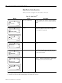
1
EtherNet/IP Media
Planning and
Installation Manual
Installation Instructions
Important User Information
Because of the variety of uses for the products described in this
publication, those responsible for the application and use of this
control equipment must satisfy themselves that all necessary steps
have been taken to assure that each application and use meets all
performance and safety requirements, including any applicable laws,
regulations, codes and standards.
The illustrations, charts, sample programs and layout examples shown
in this guide are intended solely for purposes of example. Since there
are many variables and requirements associated with any particular
installation, Allen-Bradley does not assume responsibility or liability
(to include intellectual property liability) for actual use based upon
the examples shown in this publication.
Allen-Bradley publication SGI-1.1, Safety Guidelines for the
Application, Installation and Maintenance of Solid-State Control
(available from your local Allen-Bradley office), describes some
important differences between solid-state equipment and
electromechanical devices that should be taken into consideration
when applying products such as those described in this publication.
Reproduction of the contents of this copyrighted publication, in whole
or part, without written permission of Rockwell Automation, is
prohibited.
Allen-Bradley is a trademark of Rockwell Automation.
Ethernet is a trademark of Digital Equipment Corporation, Intel, and Xerox Corporation.
Throughout this manual we use these notes to make you aware of
safety considerations:
WARNING
!
ATTENTION
!
Identifies information about practices or
circumstances that have the potential to create an
explosion hazard.
Identifies information about practices or
circumstances that can lead to personal injury or
death, property damage or economic loss.
Warning and Attention statements help you to:
• identify a hazard
• avoid a hazard
• recognize the consequences
IMPORTANT
Identifies information that is critical for successful
application and understanding of the product.
Rockwell Automation
Support
Rockwell Automation offers support services worldwide, with over 75
sales/support offices, 512 authorized distributors and 260 authorized
systems integrators located throughout the United States alone, as well
as Rockwell Automation representatives in every major country in the
world.
Local Product Support
Contact your local Rockwell Automation representative for:
•
•
•
•
sales and order support
product technical training
warranty support
support service agreements
Technical Product Assistance
If you need to contact Rockwell Automation for technical assistance,
call your local Rockwell Automation representative, or call Rockwell
directly at: 1 440 646-6800.
For presales support, call 1 440 646-3NET.
You can also obtain technical assistance online from the following
Rockwell Automation WEB sites:
• www.ab.com/mem/technotes/kbhome.html (knowledge base)
• www.ab.com/networks/eds (electronic data sheets)
Your Questions or Comments on this Manual
If you find a problem with this manual, please notify us of it on the
enclosed Publication Problem Report.
Preface
About This Manual
Who Should Use
This Manual
This manual is intended for control engineers who are responsible for
designing, implementing, and maintaining an industrial control system
using EtherNet/IP (Ethernet Industrial Protocol). This manual
describes the required media components and how to plan for and
install these required components.
What This Manual Contains
This manual contains the following information:
• Chapter 1 provides a QuickStart.
• Chapter 2 provides an overview of Ethernet media in a control
system application.
• Chapter 3 provides guidelines for planning your EtherNet/IP
media system.
• Chapter 3 provides guidelines for installing your EtherNet/IP
media system.
• Chapter 5 provides procedures for troubleshooting your
EtherNet/IP media system
Related Publications
Refer to the following Rockwell publications for additional
information on planning your Ethernet/IP network.
• EtherNet/IP Performance and Application Guide, publication
number ENET-AP001A-EN-P
• Industrial Automation Wiring and Grounding Guidelines,
publication number 1770-4.1
1
Publication ENET-IN001A-EN-P - January 2001
P-2
About This Manual
Publication ENET-IN001A-EN-P - January 2001
Table of Contents
Chapter 1
EtherNet/IP Media
System QuickStart
What this Chapter Contains. . . . . . . . . . . . . . . . . . . . . . . . . . . 1-1
Planning Your Network . . . . . . . . . . . . . . . . . . . . . . . . . . . . . 1-1
Media Selection Guide . . . . . . . . . . . . . . . . . . . . . . . . . . . . . . 1-2
Which Data Rate Should You Use? . . . . . . . .
Network Security . . . . . . . . . . . . . . . . . . . . .
Hubs . . . . . . . . . . . . . . . . . . . . . . . . . . . . . .
Switches. . . . . . . . . . . . . . . . . . . . . . . . . . . .
Placement of Switches or Hubs (Environment
Commensurate with Manufacturer’s Limits) . .
How Many Ports Do You Need? . . . . . . . . . .
Bulkheads . . . . . . . . . . . . . . . . . . . . . . . . . .
Patch Panels. . . . . . . . . . . . . . . . . . . . . . . . .
Selecting Cable to Suit the Environment . . . .
When to Use Shielded (STP)
or Non-Shielded (UTP) Cable . . . . . . . . . . . .
Grounding of Shielded Cables. . . . . . . . . . . .
Know Your Segment Lengths and Limits . . . .
Planning Your Cable Routing . . . . . . . . . . . .
Installing the Cable. . . . . . . . . . . . . . . . . . . .
Terminating Cable Ends . . . . . . . . . . . . . . . .
Connecting Network Devices . . . . . . . . . . . .
IP67 Sealed RJ45 Connectors. . . . . . . . . . . . .
Verifying and Troubleshooting the Network .
.
.
.
.
.
.
.
.
.
.
.
.
.
.
.
.
.
.
.
.
1-2
1-2
1-2
1-2
.
.
.
.
.
.
.
.
.
.
.
.
.
.
.
.
.
.
.
.
.
.
.
.
.
1-3
1-3
1-3
1-3
1-3
.
.
.
.
.
.
.
.
.
.
.
.
.
.
.
.
.
.
.
.
.
.
.
.
.
.
.
.
.
.
.
.
.
.
.
.
.
.
.
.
.
.
.
.
.
1-4
1-4
1-4
1-4
1-4
1-4
1-5
1-5
1-5
Chapter 2
Overview of the EtherNet/IP
Media System
What this Chapter Contains. . . . . . . . . . . . . . . . . . . . . . . . . . .
Industrial Control System Applications . . . . . . . . . . . . . . . . . .
Information Applications . . . . . . . . . . . . . . . . . . . . . . . . . .
Control Applications . . . . . . . . . . . . . . . . . . . . . . . . . . . . .
System Components . . . . . . . . . . . . . . . . . . . . . . . . . . . . . . . .
Ethernet Backbone . . . . . . . . . . . . . . . . . . . . . . . . . . . . . .
Routers. . . . . . . . . . . . . . . . . . . . . . . . . . . . . . . . . . . . . . .
Bridges. . . . . . . . . . . . . . . . . . . . . . . . . . . . . . . . . . . . . . .
Hubs . . . . . . . . . . . . . . . . . . . . . . . . . . . . . . . . . . . . . . . .
Ethernet Switches . . . . . . . . . . . . . . . . . . . . . . . . . . . . . . .
Gateways . . . . . . . . . . . . . . . . . . . . . . . . . . . . . . . . . . . . .
Segments . . . . . . . . . . . . . . . . . . . . . . . . . . . . . . . . . . . . .
Point to Point Connections (Horizontal Cabling) . . . . . . . .
Connectors . . . . . . . . . . . . . . . . . . . . . . . . . . . . . . . . . . . .
2-1
2-1
2-2
2-2
2-3
2-4
2-4
2-4
2-5
2-5
2-6
2-6
2-7
2-7
Standard RJ45 Connectors . . . . . . . . . . . . . . . . . . . . 2-7
IP67 Sealed RJ45 Connectors. . . . . . . . . . . . . . . . . . 2-8
Patch Panels . . . . . . . . . . . . . . . . . . . . . . . . . . . . . . . . . . . 2-8
Enclosures . . . . . . . . . . . . . . . . . . . . . . . . . . . . . . . . . . . . 2-9
Bulkhead Connectors for NEMA Enclosures . . . . . . . . . . . 2-11
i
Publication ENET-IN001A-EN-P - January 2001
Table of Contents
ii
Chapter 3
Planning Your EtherNet/IP
Cable System
What this Chapter Contains. . . . . . . . . . . . . . . . . . . . . . . . . . .
Planning Your System . . . . . . . . . . . . . . . . . . . . . . . . . . . . . .
Determining Connectivity to the Backbone . . . . . . . . . . . .
Network Security . . . . . . . . . . . . . . . . . . . . . . . . . . . . . . .
Determining the Number of Devices and Ports. . . . . . . . . .
Horizontal Segment Lengths and Limits . . . . . . . . . . . . . . .
Use of Fast Ethernet (100 Mbps) . . . . . . . . . . . . . . . . . . . .
Use of Shielded (STP) Cable . . . . . . . . . . . . . . . . . . . . . . .
Grounding of Shielded Cables . . . . . . . . . . . . . . . . . . . . . .
Grounding and Bonding of the Network . . . . . . . . . . . . . .
Selecting Cable . . . . . . . . . . . . . . . . . . . . . . . . . . . . . . . . .
3-1
3-2
3-2
3-2
3-2
3-3
3-3
3-4
3-4
3-6
3-6
Oil Resistant Jackets . . . . . . . . . . . . . . . . . . . . . . . . 3-6
Plenum Rated Cables . . . . . . . . . . . . . . . . . . . . . . . 3-6
Weld Splatter Proofing Cables . . . . . . . . . . . . . . . . . 3-7
Highflex. . . . . . . . . . . . . . . . . . . . . . . . . . . . . . . . . 3-7
IP67 Sealed Connectors. . . . . . . . . . . . . . . . . . . . . . . . . . . 3-7
Placement of Switches or Hubs . . . . . . . . . . . . . . . . . . . . . 3-7
Selecting and Locating the I/O . . . . . . . . . . . . . . . . . . . . . 3-8
Use of Bulkheads . . . . . . . . . . . . . . . . . . . . . . . . . . . . . . . 3-8
Planning Your Cable Routing . . . . . . . . . . . . . . . . . . . . . . 3-8
General Wiring Guidelines . . . . . . . . . . . . . . . . . . . . . . . . 3-9
Ambient Temperature . . . . . . . . . . . . . . . . . . . . . . . 3-9
Precautions about Conduit Installations
of UTP Cables . . . . . . . . . . . . . . . . . . . . . . . . . . . 3-10
Wiring External to Enclosures . . . . . . . . . . . . . . . . 3-10
Wiring Inside Enclosures. . . . . . . . . . . . . . . . . . . . 3-10
Surge Suppression . . . . . . . . . . . . . . . . . . . . . . . . . . . . . 3-11
Use of Ferrite Beads . . . . . . . . . . . . . . . . . . . . . . . . . . . . 3-11
Chapter 4
Installing the EtherNet/IP
Media System
Publication ENET-IN001A-EN-P - January 2001
What this Chapter Contains. . . . . . . . . . . . . . . . . . . . . . . . . . .
Installing the Point-to-Point Horizontal Cable . . . . . . . . . . . . .
Terminating the Cable Ends . . . . . . . . . . . . . . . . . . . . . . . . . .
Required Tools . . . . . . . . . . . . . . . . . . . . . . . . . . . . . . . . .
Terminating UTP Cable . . . . . . . . . . . . . . . . . . . . . . . . . . .
Terminating STP Cable . . . . . . . . . . . . . . . . . . . . . . . . . . .
Cable Routing . . . . . . . . . . . . . . . . . . . . . . . . . . . . . . . . . .
Installing the Switches. . . . . . . . . . . . . . . . . . . . . . . . . . . .
Installing Bulkheads . . . . . . . . . . . . . . . . . . . . . . . . . . . . .
Installing the Cable . . . . . . . . . . . . . . . . . . . . . . . . . . . . . .
Connection of Diagnostic and Maintenance Equipment . . .
4-1
4-1
4-2
4-2
4-3
4-6
4-8
4-8
4-8
4-9
4-9
Table of Contents
iii
Chapter 5
Verifying and Troubleshooting
Your EtherNet/IP Network
What This Chapter Contains . . . . . . . . . . . . . . . . . . . . . . . . . . 5-1
Verifying Terminated Cable Segments . . . . . . . . . . . . . . . . . . . 5-1
The MediaChecker Diagnostic Tool . . . . . . . . . . . . . . . . . . 5-2
Using the 1788-MCHKR MediaChecker . . . . . . . . . . . . . . . . . . 5-2
Setting Up the 1788-MCHKR MediaChecker . . . . . . . . . . . . 5-3
Using the TEST Function . . . . . . . . . . . . . . . . . . . . . . . . . . 5-4
Testing Twisted Wire Pairs . . . . . . . . . . . . . . . . . . . . . . . . 5-5
Testing the Wire Map (WIRE MAP) . . . . . . . . . . . . . . . . . . 5-5
Measuring Cable Length (LENGTH) . . . . . . . . . . . . . . . . . . 5-7
Measuring the Distance to a Short . . . . . . . . . . . . . . . . . . . 5-8
MediaChecker Failure Detection . . . . . . . . . . . . . . . . . . . 5-10
Notes
Index
Publication ENET-IN001A-EN-P - January 2001
Table of Contents
iv
Publication ENET-IN001A-EN-P - January 2001
Chapter
1
EtherNet/IP Media System QuickStart
What this Chapter Contains
Planning Your Network
This chapter provides an overview of what you need to consider in
planning your network selecting the appropriate media. The following
table describes where to find specific information.
For information about
See page
Planning Your Network
1-1
Media Selection Guide
1-2
Your procedure for planning and laying out your Ethernet network
should consist of the following steps:
1. Determine the type of application:
a. Information
b. Control
2. Determine if sealed media (IP67) is required (see pages 2-7 to 2-8).
3. Consider your information system:
a. Determine placement of major components
b. Determine distance of each connection, the placement of
switches may need to be adjust to meet Ethernet’s 100 meter
segment limit and to accommodate devices.
c. Determine environmental requirements
1) temperature
2) presence of chemicals
3) protection requirements
d. Select and order materials based on environments
e. Install system
f. Verify system
4. Consider your control system:
a. Determine placement of major components
b. Determine distance of each connection, the placement of
switches may need to be adjust to meet Ethernet’s 100 meter
segment limit and to accommodate devices.
1
Publication ENET-IN001A-EN-P - January 2001
1-2
EtherNet/IP Media System QuickStart
c. Determine environmental requirements
1) temperature
2) presence of chemicals
3) protection requirements
4) noise levels
5) cable routing
d. Select and order materials based on above requirements
e. Install system
f. Verify system
Media Selection Guide
This section provides an overview of the main considerations you
should take into account when selecting your network media and
laying out your network.
Which Data Rate Should You Use?
For best noise immunity use the lowest data rate at which your
application will run.
Network Security
The control network must be isolated from the office environment
and the internet. You must provide appropriate security through the
use of gateways, firewalls, routers, and/or appropriate security
software. See page 3-2.
Hubs
Pay careful attention to the use of hubs. Hubs do not provide security
and do not help to control collisions among signals from devices
competing for the network media. Collisions reduce throughput of the
network. See page 2-5.
Switches
Switches provide virtual connections that help to control collisions
and reduce traffic on the network. In a control application, in which
real time data access is critical, network switches may be required in
place of hubs.
See page 2-5 for more information.
Publication ENET-IN001A-EN-P - January 2001
EtherNet/IP Media System QuickStart
1-3
Placement of Switches or Hubs (Environment Commensurate with
Manufacturer’s Limits)
Placement of your switches should be carefully planned to minimize
cable lengths and the effects of the environment. Switches or hubs
should be industrially hardened or installed in a suitable enclosure to
protect them from static electricity, temperature extremes, humidity,
and Electro-Magnetic Interference (EMI) generated by nearby
equipment. Be sure to consider the temperature of the enclosures
(closets) where the switches are to be located. Many switches cannot
withstand the temperatures in an industrial environment and the
enclosures may not be air conditioned. Refer to the manufacturer’s
specifications.
How Many Ports Do You Need?
While planning your network, you must determine the number of
switches you will need and the number of ports for each switch
chassis. Each network device will require a corresponding switch port
for connection to the network. The number of ports per switch chassis
will also depend on your physical network layout.
Bulkheads
Bulkheads should be used wherever connectivity through an
enclosure is required. The connector should be located within the
enclosure to minimize exposure to liquids, dusts, and vibration. Plan
your mounting location in such a way that the connector is not
exposed to damage from plant activity. See pages 2-9 to 2-11.
Patch Panels
Patch panels should be used only when necessary to maintain
flexibility. See page 2-8.
Selecting Cable to Suit the Environment
When selecting cable, the jacket construction must be compatible with
the temperature and chemicals in the environment. Chemicals can be
absorbed into the jackets and wire insulation, causing plastic
deterioration and performance degradation.
Do not overlook the cable electrical specifications over temperature,
as many off the shelf cables are not designed to meet TIA/EIA
standards at industrial temperatures. Cable Jackets maybe easily
damaged even at low temperature ranges.
See page 3-6 for more information.
Publication ENET-IN001A-EN-P - January 2001
1-4
EtherNet/IP Media System QuickStart
When to Use Shielded (STP) or Non-Shielded (UTP) Cable
STP cable provides an added level of noise immunity. If you know
that your application is in a high noise environment then shielded
cable media should be considered, or you should consider using an
alternative control network such as ControlNet. See page 3-4.
Grounding of Shielded Cables
Single point grounds are very important for eliminating and reducing
ground loops in shielded cable (see pages 3-4 to 3-6).
Consult the installation data sheet for each device installed for that
device’s grounding requirements. Most Hub/Switch manufactures
require their equipment to be grounded. Note that grounding the
equipment will ground the shield when connected via a shielded RJ45
connector.
Know Your Segment Lengths and Limits
Standard Ethernet limits each segment of horizontal wiring to 100
meters or to 90 meters horizontal wiring with two 5 meter jumpers.
Some applications will require more jumpers. In these applications the
total length of horizontal wiring must be adjusted to compensate for
the added loss of each connector pair.
Planning Your Cable Routing
Route your cable as described on pages 3-8 to 3-11 in this manual.
• If your application is in a high noise environment then you
should plan to use shielded cable.
• Segments should be as short as possible.
Installing the Cable
Install the cable per the manufacturer’s requirements for bend radius
and pull strength. Consult the cable manufacturer when installing UTP
cables in conduit, as the electrical performance can be affected by the
conduit metal. Avoid routing near equipment that generates strong
electric or magnetic fields. See chapter 3 for more information.
Terminating Cable Ends
The performance of your system depends on the cable termination.
Careful cable end preparation will help to install the connector and
assure a successful connector installation. See pages 4-2 to 4-8.
Publication ENET-IN001A-EN-P - January 2001
EtherNet/IP Media System QuickStart
1-5
Connecting Network Devices
Connect the devices to your network per the manufacturer’s
instructions.
IP67 Sealed RJ45 Connectors
Use the appropriate connectors for the environment. If your
application requires cable and connectors to be exposed to liquids or
dust, you should protect the connections from invasion from these
types of contaminates. Use IP67 sealed connectors (see page 2-8) and
bulkheads to help maintain a seal.
You should also consider using sealed connectors if there is exposure
to high vibrations.
Verifying and Troubleshooting the Network
Each cable segment should be verified for proper connection. Clear all
errors before using the cable. Miss-paired or crossed wires will cause
network errors and failures. See chapter 5 for more information.
Publication ENET-IN001A-EN-P - January 2001
1-6
EtherNet/IP Media System QuickStart
Publication ENET-IN001A-EN-P - January 2001
Chapter
2
Overview of the EtherNet/IP Media System
What this Chapter Contains
The following table describes what this chapter contains and where to
find specific information.
For information about
Industrial Control System
Applications
1
See page
Industrial Control System Applications
2-1
Information Applications
2-2
Control Applications
2-2
System Components
2-3
Ethernet Backbone
2-4
Routers
2-4
Bridges
2-4
Hubs
2-5
Ethernet Switches
2-5
Gateways
2-6
Segments
2-6
Point to Point Connections (Horizontal Cabling)
2-7
Connectors
2-7
Standard RJ45 Connectors
2-7
IP67 Sealed RJ45 Connectors
2-8
Patch Panels
2-8
Enclosures
2-9
Bulkhead Connectors for NEMA Enclosures
2-11
Ethernet is widely used in the business world for information
applications. The technology has wide availability, familiarity, and cost
benefits, making it attractive for use in industrial control systems.
However, information applications and control applications have
different requirements as described in the following sections.
Publication ENET-IN001A-EN-P - January 2001
2-2
Overview of the EtherNet/IP Media System
Information Applications
In an industrial control system, information applications typically are
used for downloading PLC programs, monitoring processes, and
gathering statistics, process data, and diagnostics. The performance of
this type of application is not as critical as a control application where
speed, throughput, response time, and downtime are critical to a
manufacturing process.
Control Applications
Control applications require fast response times and high throughput
of data. Network availability is of highest importance. Intrusion into
the network has to be limited by the use of firewalls and bridges. The
installation of the network must be robust enough to prevent damage
and noise ingress that could result in process downtime.
Of particular concern, commercial off the shelf Ethernet products are
not compatible with high noise environments, as may be found in an
industrial manufacturing plant. Among the problems encountered with
low cost off the shelf commercial products are:
• low common mode rejection ratio (CMRR)
• capacitance imbalances, further degrading the CMRR
performance
• attenuation too high over temperature
• impedance tolerance too wide (15%) resulting in high system
reflections
Moreover, control network components must be able to perform in
stressful environments, which may include:
•
•
•
•
Publication ENET-IN001A-EN-P - January 2001
harsh chemicals
electrical noise
extreme temperatures and humidity
vibrations
Overview of the EtherNet/IP Media System
System Components
2-3
An example of an EtherNet/IP control system is shown in the
following figure.
Figure 2.1 - EtherNet/IP Industrial Control System
Firewall/Router
PC running
RSLinx
ControlLogix with
Processor and
Ethernet module
PanelView
Ethernet
Switch
Ethernet
Switch
FLEX I/O System with
Ethernet Adaptor
ControlLogix Gateway
To DeviceNet
Network
To DH+
To ControlNet
Network
Network
Ethernet to RS-232-C Interface
ControlLogix I/O
with Ethernet module
MicroLogix Processor
Ethernet
Switch
Ethernet SLC 5/05
Processor
Powermonitor 3000
Master with Ethernet
Communication Card
Ethernet PLC-5
Processor
Powermonitor II
Ethernet Communication
Card
31159-M
The following sections describe the basic media components of an
EtherNet/IP industrial control system.
Publication ENET-IN001A-EN-P - January 2001
2-4
Overview of the EtherNet/IP Media System
Ethernet Backbone
The Ethernet backbone is the part of the network that handles the
major traffic. It employs the highest-speed transmission paths in the
network and may also run the longest distance. A backbone can span
a large geographic area or be small enough to be contained in a single
cabinet. Smaller networks (or subnets) are attached to the backbone.
Routers
Routers serve as an internet backbone, interconnecting all networks in
an enterprise. This architecture strings several routers together via a
high-speed LAN topology such as Fast Ethernet or Gigabit Ethernet.
Routers are also the backbone of the Internet.
Routers forward data packets from one local area network (LAN) or
wide area network (WAN) to another. Based on routing tables and
routing protocols, routers read the network address in each
transmitted frame and make a decision on how to send it based on the
most expedient route (traffic load, line costs, speed, bad lines, etc.).
Routers are used to segment LANs in order to balance traffic within
workgroups and as “firewalls” to filter traffic for security purposes and
policy management. Routers are also used at the edge of the network
to connect remote locations.
Routers operate at the network layer and can only route a message
that is transmitted by a routable protocol such as IP. Because routers
have to inspect the network address in the protocol, they do more
processing and add more overhead than a bridge or switch (see the
following sections), which both work at the data link layer (layer 2).
Because of the processing overhead, I/O data can not be passed
through a router in real time.
Bridges
A bridge is a device that connects two network segments together.
The segments may be of similar or dissimilar types. The bridge is
inserted into a network to segment it and keep traffic contained within
the segments to improve performance.
Publication ENET-IN001A-EN-P - January 2001
Overview of the EtherNet/IP Media System
2-5
Bridges learn from experience and build and maintain address tables
of the nodes on the network. By monitoring which station
acknowledged receipt of an address, they learn which nodes belong
to the segment.
Bridges work at the data link layer (layer 2) and are protocol
independent, while routers work at the network layer (layer 3) and
are protocol dependent. Since bridges do not have to read the
protocol to obtain the routing information, they are faster than routers.
Bridges with more than two ports (multiport bridges) perform a
switching function (see page 2-5).
Hubs
IMPORTANT
You may experience high levels of collisions and
reduced throughput if you use hubs. You should
carefully plan your requirements before installing
hubs in a control system.
A hub is a central connecting device in a network that joins
communications lines together in a star configuration. Passive hubs
are just connecting units that add nothing to the data passing through
them. Active hubs, also sometimes called “multiport repeaters,”
regenerate the data bits in order to maintain a strong signal. There are
also “intelligent” hubs that provide some added functionality.
When designing your control system, it is important to understand that
all devices connected to a hub compete for the network media,
resulting in collisions and decreased network bandwidth. As a result,
hubs are more suitable for use in information networks than in control
networks.
Ethernet Switches
In recent years, hub technology has been supplanted by a new high
speed switch technology that allows traffic between any two ports on
the switch to pass through without contention. Switches are basically
multiport bridges that can simultaneously move frames between pairs
of ports at full wire speed. For example, a 16-port 10BaseT hub shares
a 10 Mbps bandwidth with all 16 attached nodes. By replacing the
hub with a switch, each sender/receiver pair has the full 10 Mbps
capacity, so a 16-port 10BaseT switch would effectively have an 80
Mbps bandwidth supporting eight pairs. Capacity can be further
increased by using full-duplex switches.
Publication ENET-IN001A-EN-P - January 2001
2-6
Overview of the EtherNet/IP Media System
A switch segments a network into many parallel dedicated lines to
produce a contentionless architecture, as shown in figure 2.2.
Figure 2.2 - Hubs Versus Switches
Switch
Hub
All devices contend for media
and share bandwidth
Each sender/receiver pair
has full network bandwidth
Switches are available for both standard 10 Mbps Ethernet and 100
Mbps Fast Ethernet. In a control application, in which real time data
access is critical, network switches may be required in place of hubs.
Gateways
The term “gateway” can have different meanings. It may refer to a
device that performs protocol conversion between different types of
networks or applications. Such gateways function at the transport
layer and above. They perform complete conversions from one
protocol to another rather than simply support one protocol from
within another. Sometimes routers can implement such gateway
functions.
A gateway can also mean a device that acts as a go-between
connecting two or more networks that use the same protocols. In this
case, the gateway functions as an entry/exit point to the network.
Transport protocol conversion may not be required, but some form of
processing is typically performed.
Segments
A segment is a section of a local area network (LAN) that is used by a
particular workgroup or department and separated from the rest of the
LAN by a bridge, router, or switch. Networks are divided into multiple
segments for security and to improve traffic flow by filtering out
packets that are not destined for the segment.
Publication ENET-IN001A-EN-P - January 2001
Overview of the EtherNet/IP Media System
2-7
Point to Point Connections (Horizontal Cabling)
Point to point connections are direct connections from one device to
another via an Ethernet cable segment as shown in figure 2.3. No
hubs, switches, or other connective devices are used. Additional
examples are shown in figures 2.8 and 2.9 on page 2-10.
Figure 2.3 - Point to Point Connections
31181-M
Point to point connections must end in a null termination as shown in
figure 2.4.
Figure 2.4 - Null Termination (No Switches)
Connector #1
568A/B
1
2
3
4
5
6
7
8
1
2
3
4
5
6
7
8
Connector #2
568A/B
31193-M
Connectors
Connectors play an important role in sealing and vibration
performance. RJ45 connector technology was selected for EtherNet/IP
because it is already accepted as the standard.
Standard RJ45 Connectors
IMPORTANT
Not all RJ45 connectors are suitable for harsh
environments. You must carefully select your RJ45
connector for the intended environment.
Standard “off the shelf” RJ45 connectors are not sealed to meet the
IP67 specification for EtherNet/IP (see following section). In addition,
their common mode rejection ratio (CMRR) can be low and the
amount of cross talk can be too high for industrial applications.
Standard RJ45 connectors also are not generally designed to operate in
high vibration environments.
Publication ENET-IN001A-EN-P - January 2001
2-8
Overview of the EtherNet/IP Media System
IP67 Sealed RJ45 Connectors
Figure 2.5 - IP67 Sealed RJ45 Connectors
31178-M
The IP67 standard specifies that connectors can withstand immersion
in water at a depth of 1 meter for 1 hour without incursion. IP67
sealed RJ45 connectors have the following features:
•
•
•
•
M18 style threaded flange
standard RJ45 jack
seal at face of jack
design accommodating PCB mount, flange mount, or bulkhead
mount
Patch Panels
A patch panel is a group of sockets that function as a manual
switching center between incoming and outgoing lines in a
communications system. They are typically used for flexibility in
network configuration, especially in an office environment. In an
industrial control system patch panels may be used to interface I/O
devices and switches or hubs.
Publication ENET-IN001A-EN-P - January 2001
Overview of the EtherNet/IP Media System
2-9
Enclosures
In an industrial environment, the controller and switch are often
mounted in a controlled environment inside a NEMA enclosure, with
access via bulkhead connectors. Some typical examples are shown in
the following figures.
Figure 2.6 - I/O Interfaced Via Patch Panels and a Switch
Devices
Enclosure
PLC
Patch Panels
Switch
Patch Panel
RJ45 Bulkhead
31182-M
Publication ENET-IN001A-EN-P - January 2001
2-10
Overview of the EtherNet/IP Media System
Figure 2.7 - I/O Interfaced Via Single Patch Panel and Switch
Enclosure
PLC
Switch
Devices
Patch Panel
RJ45 Bulkhead
31179-M
Note that patch panels are not specifically required for industrial
Ethernet. Controllers and I/O devices may be directly connected in a
point to point configuration or connected via hubs or switches, as
shown in the following figures.
Figure 2.8 - Small Point to Point System (No Patch Panel - Direct Connect)
Enclosure
Simple 2 Node
Configuration
PLC
NULL Cable
Device
RJ45 Bulkhead
31184-M
Publication ENET-IN001A-EN-P - January 2001
Overview of the EtherNet/IP Media System
2-11
Figure 2.9 - Larger Point to Point System (No Patch Panels)
Enclosure
PLC
Switch
Devices
RJ45 Bulkhead
or Wire Gland
31185-M
Bulkhead Connectors for NEMA Enclosures
Bulkheads should be used wherever connectivity through an
enclosure is required. A bulkhead connector or gland should be used
where cables enter or exit the cabinet to maintain the enclosure seal.
Publication ENET-IN001A-EN-P - January 2001
2-12
Overview of the EtherNet/IP Media System
Publication ENET-IN001A-EN-P - January 2001
Chapter
3
Planning Your EtherNet/IP Cable System
What this Chapter Contains
Use this chapter to determine your network requirements. The
following table describes what this chapter contains and where to find
specific information.
For information about
See page
Planning Your System
3-2
Determining Connectivity to the Backbone
3-2
Network Security
3-2
Determining the Number of Devices and Ports
3-2
Horizontal Segment Lengths and Limits
3-3
Use of Fast Ethernet (100 Mbps)
3-3
Use of Shielded (STP) Cable
3-4
Grounding of Shielded Cables
3-4
Grounding and Bonding of the Network
3-6
Selecting Cable
3-6
Placement of Switches or Hubs
3-7
Selecting and Locating the I/O
3-8
Use of Bulkheads
3-8
Planning Your Cable Routing
3-8
General Wiring Guidelines
3-9
Surge Suppression
3-11
Use of Ferrite Beads
3-11
After reading this chapter you may wish to consult the engineering
drawings of your facility for specific information concerning the best
location for installing your network.
1
Publication ENET-IN001A-EN-P - January 2001
3-2
Planning Your EtherNet/IP Cable System
Planning Your System
Determining Connectivity to the Backbone
The following sections describe some of the considerations you must
take into account when designing and securing your network.
Figure 3.1 - Backbone Connectivity
Company
LAN
Ethernet Backbone (fiber/copper)
Firewall/
Router
Switch
Switch
Workcell 1
Workcell 2
31186-M
Network Security
Control applications may require access to the control network 100%
of the time. Intrusions by other networks into the control network
could cause processing delays and loss of control. For this reason, the
control network must be isolated from the office environment and the
internet. You must provide appropriate security through the use of
gateways, firewalls, routers, and/or appropriate security software.
IT personnel, in particular, must be made aware that inadvertent
intrusions resulting from system maintenance and housekeeping,
network upgrades, or broadcast storms can disrupt the control system.
Determining the Number of Devices and Ports
The number of ports you need depends on the number of devices
you want to connect to the network. You will need a port for each
node on a segment. If you plan to add nodes at a later date, you
should consider ordering and installing the cable and connectors for
these additional nodes when you install the initial network. This will
minimize disruption to the network during operation.
Publication ENET-IN001A-EN-P - January 2001
Planning Your EtherNet/IP Cable System
3-3
Consider the number and locations of the following when
determining how many ports you will need on your network:
•
•
•
•
•
workstations
I/O racks
PanelViews
bridges, routers, switches and/or hubs
future I/O
Horizontal Segment Lengths and Limits
The total length of each horizontal cable segment must not exceed
100 meters between any two active devices. Jumpers are limited to a
total length of 10 meters, which must be subtracted from the 100
meter limit. For example, if you have a 5 meter jumper at each end of
a cable segment, the segment is limited to a maximum length of 90
meters.
Use of Fast Ethernet (100 Mbps)
A higher data rate will provide a wider network bandwidth. But
generally the higher the data rate the less noise tolerant a
communications network will be. Use of fast Ethernet (100 Mbps) for
control is the most critical application in terms of noise. Additionally,
the network must be error free, as the greater the number of errors in
an EtherNet/IP system the greater the network traffic. When traffic
increases so does response time. If your application depends upon
short response time, safeguards must be taken to minimize errors due
to noise and other causes of increased traffic. Throughput can be
further increased by using full-duplex communications.
For Fast Ethernet, we highly recommend the use of low noise, high
performance cables and connectors. Any degradation in noise
rejection will degrade an entire link between a switching device and
the peripheral equipment. If you are using a Fast EtherNet/IP device,
it has been specially designed for high noise rejection. Introduction of
a non EtherNet/IP device into the network may degrade the noise
rejection of the system and disrupt an otherwise functioning network.
Publication ENET-IN001A-EN-P - January 2001
3-4
Planning Your EtherNet/IP Cable System
Use of Shielded (STP) Cable
Depending on where you plan to route your cable you must select the
correct cable for the environment. Shielded cable performs better than
non-shielded cable in industrial environments. In particular, if your
application is in a high noise environment or your cable must be run
in close proximity to noise radiating sources then you should plan to
use shielded cables.
You should consider shielded cables if your application includes one
or more of the following:
• spot welding control
• Motor Control Centers
• drives greater than 10 HP
• induction welding processes
• proximity to high power RF radiation
• electrostatic processes
• high current devices (greater than 100 amps)
There are specific grounding requirements for shielded cable. These
are discussed in the following section.
Grounding of Shielded Cables
IMPORTANT
Publication ENET-IN001A-EN-P - January 2001
Shields play an important roll in providing noise
immunity for your system. However, an improperly
installed shielded cable can cause problems due to
voltage offsets in your grounding system. To
minimize the effects of ground offsets you will need
to isolate the shield at one end of the cable. In this
case the shield should be isolated at the device, not
at the switch.
Planning Your EtherNet/IP Cable System
3-5
Eliminating ground loops is extremely important in reducing noise
interference cause by ground offsets or local ground transients.
Ground offsets occur when there is a potential difference between
two earth ground points in a system. This potential difference can be
DC or AC or transient. A cable that connects the two points together
provides a secondary path for current to travel. The current through
the communications cable’s shield will couple noise into the
communications system. This noise will have a direct impact on the
signal to noise performance of the system.
Figure 3.2 - Ground Noise Loop In Shielded Cable
Shielded Cable
System
Ground
Noise Loop
V Noise
Remote
Ground
Local
Ground
31199-M
There can be as much as a 45 volt high frequency offset in ground
potential between the two ends of a 100 meter cable. This offset can
cause noise currents in the shields. Consequently, to eliminate ground
loops the cable should be grounded at the switch end only.
If your device is other than a switch (or hub) and provides a low
resistance (< 500k ohms) ground at the jack, do not connect the shield
at the device end of the cable. Breaking the ground can be
accomplished simply by cutting back the shield and insulating it from
the connector plug’s shell. See figures 3.3 and 3.4.
Figure 3.3 - Grounding of Cable Shield
Ground
Here
Switch
Do Not
Ground
Here
Network
Device
31187-M
Publication ENET-IN001A-EN-P - January 2001
3-6
Planning Your EtherNet/IP Cable System
Figure 3.4 - Null Termination of Shielded Cable
Connector #1
Switch
1
2
3
4
5
6
7
8
1
2
3
4
5
6
7
8
Null Cable
Connector #2
Device
31194-M
Grounding and Bonding of the Network
For information regarding grounding and bonding requirements for
your network, refer to Rockwell publication no. 1770-4.1, Industrial
Automation Wiring and Grounding Guidelines, and to NFPA-70, the
National Electrical code, CSA C22.1, the Canadian Electrical code,
and/or other applicable local, national, or international codes.
Selecting Cable
When selecting cable, the jacket construction must be compatible with
the temperature and chemicals in the environment. Do not overlook
the cable electrical specifications over temperature, as many off the
shelf cables are not designed to meet TIA/EIA standards at industrial
temperatures. Cable Jackets maybe easily damaged even at low
temperature ranges. Chemicals can be absorbed into the jackets and
wire insulation, causing plastic deterioration and performance
degradation. Sealed media may be required if connectors or cable
jackets are exposed to a harsh environment.
If you know that your application is in a high noise environment then
shielded cable media should be considered, or you should consider
using an alternative control network such as ControlNet.
Oil Resistant Jackets
If your application requires control of equipment that uses cutting oils
or lubricating chemicals, the selection of cable construction should
include oil resistant type jackets.
Plenum Rated Cables
Plenum installations require special material compounds in the
makeup of the cables. If your application requires cables to be run
above the ceiling then you should use Plenum rated cables.
Publication ENET-IN001A-EN-P - January 2001
Planning Your EtherNet/IP Cable System
3-7
Weld Splatter Proofing Cables
If your application requires control of welding equipment you should
carefully route your cables to reduce damage from weld splatter and
noise ingress. All cables should be routed to cross welding and motor
control cables at right angles and should never run parallel to control
cables. The cables should be protected from the weld splatter either
by an added protective sleeve or by selecting cables with the proper
jacket construction.
Highflex
Typically, Ethernet cables are constructed of 24 gauge solid copper
conductors. Hiflex requires stranded type conductor construction to
extend the life of a cable in flexing applications. Currently, there are
no EtherNet cables with stranded construction.
IP67 Sealed Connectors
If your application requires cable and connectors to be subjected to
liquid or dust contaminates, you should protect the connections from
invasion from these types of chemicals. Use IP67 sealed connectors
(see page 2-8) and bulkheads to help maintain a seal.
Placement of Switches or Hubs
You must consider the environment when selecting switches or hubs
and deciding where to place them. Unless industrially hardened or
specified, switches and hubs should be installed in a suitable
enclosure to protect them from static electricity, temperature extremes,
humidity, and Electro-Magnetic Interference (EMI) generated by
nearby equipment. Be sure to consider the temperature inside the
enclosures (closets) when planning where the switches are to be
located, since the enclosures may not be air conditioned.
The switch or hub should be grounded per the manufacturer’s
recommendations.
Refer to the Telecommunications Industry Association publication
TIA/EIA- 569-A, Telecommunications Pathways and Spaces, for
additional information.
Publication ENET-IN001A-EN-P - January 2001
3-8
Planning Your EtherNet/IP Cable System
Selecting and Locating the I/O
Consider the environment when selecting I/O and deciding where to
locate it. Review the manufacturer’s specifications with respect to:
•
•
•
•
vibration
temperature
humidity
noise
In harsh environments you may have to provide suitable enclosures
for the I/O you have chosen.
Use of Bulkheads
Bulkheads should be used wherever connectivity through an
enclosure is required. The connector should be located within the
enclosure to minimize exposure to liquids dusts and vibration. Plan
your mounting location in such a way that the connector cannot be
damaged.
Planning Your Cable Routing
Plan your cable routing very careful. You should spend sufficient time
planning how to route your cable before attempting to do so. Cables
should not be routed near equipment that generates strong electric or
magnetic fields.
In particular, you should be concerned with routing near and around:
•
•
•
•
•
lights
motors
drive controllers
arc welders
conduit
The following guidelines coincide with the guidelines for “the
installation of electrical equipment to minimize electrical noise inputs
to controllers from external sources” in IEEE standard 518-1982. When
planning your cable system there are certain installation
considerations depending on your application.
Publication ENET-IN001A-EN-P - January 2001
Planning Your EtherNet/IP Cable System
3-9
There are three categories of conductors:
Category
1
Includes:
• AC Power Lines
• High-power digital ac I/O
• High-power digital dc I/O
• Power connections (conductors) from motion drives to
motors
2
• Analog I/O lines and dc power lines for analog circuits
• Low-power digital ac/dc I/O lines
• Low-power digital I/O lines
• Ethernet I/P
3
• Low-voltage dc power lines
• Communication cables to connect between system
components within the same enclosure
General Wiring Guidelines
Follow these guidelines for wiring all EtherNet/IP cables:
• If a cable must cross power lines, it should do so at right angles.
• Route at least 1.5m (5 ft) from high-voltage enclosures, or
sources of rf/microwave radiation.
• If the conductor is in a metal wireway or conduit, each section
of the wireway or conduit must be bonded to each adjacent
section so that it has electrical continuity along its entire length,
and must be bonded to the enclosure at the entry point.
• Only shielded Ethernet cables should be placed into metal
conduit. If you need to protect or route your EtherNet cable in a
metal conduit then you must use a shielded cable. The shield
must not come in contact with the conduit at any point.
For more information on general wiring guidelines, see Rockwell
publication 1770-4.1, Industrial Automation Wiring and Grounding
Guidelines and the Telecommunications Industry Association
publication TIA/EIA-607, Grounding and Bonding Requirements.
Ambient Temperature
The ambient temperature of the environment must be considered in
specifying the cables and connectors to be installed. Some Ethernet
cables cannot survive and/or will not perform to specification in the
extreme hot and cold temperatures of industrial environments
Publication ENET-IN001A-EN-P - January 2001
3-10
Planning Your EtherNet/IP Cable System
Precautions about Conduit Installations of UTP Cables
Some UTP cables may not function properly when installed in
conduit, as the metal conduit can effect the electrical properties of an
unshielded cable. Consult the cable manufacturer when installing UTP
cables in conduit.
Wiring External to Enclosures
Cables that run outside protective enclosures are relatively long. To
minimize cross-talk from nearby cables, it is good practice to maintain
maximum separation between the Ethernet cable and other potential
noise conductors. You should route your cable following these
guidelines.
Cable in a contiguous metallic
wireway or conduit?
Route your cable at
least this distance
Yes
No
From noise sources of this strength
0.08m (3")
Category 1 conductors of less than 20 amps
0.15m (6")
ac power lines of 20 amps or more, up to 100 KVA
0.3m (12")
ac power lines greater than 100 KVA
0.15m (6")
Category 1 conductors of less than 20 amps
0.3m (12")
ac power lines of 20 amps or more, up to 100 KVA
0.6m (24")
ac power lines greater than 100 KVA
Consult your local, state, and national codes regarding the grouping of
cables. In the absence of these codes the general rule for noise
protection is a minimum distance of 3 inches from electric light and
power conductors and an additional inch for each 100 volts over 100
volts:
Voltage Level
Minimum Distance
0 - 100 V
3 inches
101 - 200 V
4 inches
201 - 300 V
5 inches
301 - 400 V
6 inches
Wiring Inside Enclosures
Cable sections that run inside protective equipment enclosures are
relatively short. As with wiring external to enclosures you should
maintain maximum separation between your Ethernet cable and
Category-1 conductors.
When you are running cable inside an enclosure, route conductors
external to all raceways in the same enclosure, or in a raceway
separate from Category-1 conductors.
Publication ENET-IN001A-EN-P - January 2001
Planning Your EtherNet/IP Cable System
Route your cable at
least this distance
3-11
From noise sources of this strength
0.08m (3")
Category 1 conductors of less than 20 amps
0.15m (6")
ac power lines of 20 amps or more, up to 100 KVA
0.6m (24")
ac power lines greater than 100 KVA
Surge Suppression
Transient Electro-Magnetic Interference (EMI) can be generated
whenever inductive loads such as relays, solenoids, motor starters, or
motors are operated by “hard contacts” such as pushbutton or selector
switches. These wiring guidelines assume you guard your system
against the effects of transient EMI by using surge-suppressors to
suppress transient EMI at its source.
Inductive loads switched by solid-state output devices alone do not
require surge suppression. However, inductive loads of ac output
modules that are in series or parallel with hard contacts require
surge-suppression to protect the module output circuits as well as to
suppress transient EMI.
Use of Ferrite Beads
Ferrite beads can provide additional suppression of transient EMI.
Fair-Rite Products Corporation manufactures a ferrite bead (part
number 2643626502) which can be slipped over category-2 and
category-3 (type cable) conductors. You can secure them with
heat-shrink tubing or tie-wraps. A cable transient EMI induced onto
the cable can be suppressed by a ferrite bead located near the end of
the cable. The ferrite bead will suppress the EMI before it enters the
equipment connected to the end of the cable.
Publication ENET-IN001A-EN-P - January 2001
3-12
Planning Your EtherNet/IP Cable System
Publication ENET-IN001A-EN-P - January 2001
Chapter
4
Installing the EtherNet/IP Media System
What this Chapter Contains
Follow the guidelines in this chapter as you install your EtherNet/IP
cabling system. The following table describes what this chapter
contains and where to find specific information.
For information about
Installing the Point-to-Point Horizontal Cable
4-1
Installing the Point-to-Point Horizontal Cable
4-2
Terminating the Cable Ends
4-2
Required Tools
4-2
Terminating UTP Cable
4-3
Terminating STP Cable
4-6
Cable Routing
4-8
Installing the Switches
4-8
Installing Bulkheads
4-8
Installing the Cable
4-9
Connection of Diagnostic and Maintenance Equipment
4-9
IMPORTANT
Installing the Point-to-Point
Horizontal Cable
See page
You should have read chapter 3, Planning an
EtherNet/IP Cable System, before you install your
network.
Install your point-to-point horizontal cable, observing your cable
supplier’s installation instructions and the following guidelines:
• Bend Radius: the bend radius should not exceed 4 times the
cable diameter.
• Pull Strength: the pull strength should not exceed 90 lbs or the
maximum specified on the manufacturer’s data sheet.
1
Publication ENET-IN001A-EN-P - January 2001
4-2
Installing the EtherNet/IP Media System
Terminating the Cable Ends
The performance of your system depends on the cable termination.
Careful cable end preparation will help to install the connector and
assure a successful connector installation. Pay particular attention to
the amount of un-twisting of the conductor pairs. Un-twist only
enough length to route the wires within the connector body. Refer to
the procedures described in the following sections.
IMPORTANT
Not all RJ45 connectors are industrial grade and may
not meet shock and vibration requirements or be
suitable for your environmental conditions. If your
connectors must meet IP67 specifications you must
use sealed connectors.
Required Tools
You will need the following tools to terminate the ends of your UTP
or STP Ethernet cable.
• cable cutting tool supplied with Rockwell Automation tool kit,
1786-CTK
• cable jacket stripping tool, such as Orthronics Easy Strip™
• crimp tool supplied with Rockwell Automation tool kit
1786-CTK and optional RJ-45 die set
Publication ENET-IN001A-EN-P - January 2001
Installing the EtherNet/IP Media System
4-3
Terminating UTP Cable
Terminate UTP cable as follows:
1. First strip back 1 inch of jacket using an appropriate jacket strip
tool. Be careful not to cut the insulation of the wire. If you
damage the insulation, cut off the end of the cable and start over.
Figure 4.1 - Stripping the Cable Jacket
1"“
31188-M
1"“
31189-M
2. Separate the individual wire pairs. Un-twist only back to the
jacket.
Publication ENET-IN001A-EN-P - January 2001
4-4
Installing the EtherNet/IP Media System
3. Align the wires as shown in figure 4.2 below:
Figure 4.2 - Alignment of Wires
Green/White
Green
Orange/White
Blue
Blue/White
Brown
Orange
Brown/White
31190-M
4. Hold the conductors in the proper orientation and trim off excess
length using a pair of sharp cutters. The finished length beyond
the jacket should be less than 0.5 inches.
5. Confirm the correct orientation of the conductors and insert the
conductors into the connector body. Note that each wire has it’s
own slot.
Figure 4.3 - Inserting the Wires into the Connector Body
Brown
Green/White
31191-M
6. Push the cable into the connector body until all the wires touch
the end of the connector body. The jacket should be far enough
into the connector body that the cable clamp will engage and
hold.
Publication ENET-IN001A-EN-P - January 2001
Installing the EtherNet/IP Media System
4-5
7. Insert the connector into the crimp tool and crimp the connector.
Figure 4.4 - Crimping the Connector
8. Check the crimp by pulling gently on the connector. If the jacket
or conductors slide out, cut the connector off and start over.
9. Electrically test the connection using the 1788-MCHKR test tool.
See chapter 5.
Publication ENET-IN001A-EN-P - January 2001
4-6
Installing the EtherNet/IP Media System
Terminating STP Cable
Terminate STP cable as follows:
1. First strip back 1 inch of jacket and shield foil using an the jacket
strip tool. Discard the shield foil. Be careful not to cut the
insulation of the wires. If you damage the insulation, cut off the
end of the cable and start over.
Figure 4.5 - Stripping the Cable Jacket
1"“
31188-M
1"“
31189-M
2. Separate the individual wire pairs. Un-twist only back to the
jacket.
3. Fold the drain wire back in line with the cable.
Publication ENET-IN001A-EN-P - January 2001
Installing the EtherNet/IP Media System
4-7
4. Align the wires as shown in figure 4.6 below:
Figure 4.6 - Alignment of Wires
Green/White
Green
Orange/White
Drain
Blue
Blue/White
Brown
Orange
Brown/White
31190-M
5. Hold the conductors in the proper orientation and trim off the
excess length using a pair of sharp cutters. The finished length
beyond the jacket should be less than 0.5 inches.
6. Confirm the correct orientation of the conductors and insert the
conductors into the connector body. Note that each wire has it’s
own slot.
Figure 4.7 - Inserting the Wires into the Connector Body
Brown
Green/White
31191-M
7. Push the cable into the shielded connector body until all the wires
touch the end of the connector body. The jacket should be far
enough into the connector body that the cable clamp will engage
and hold.
Publication ENET-IN001A-EN-P - January 2001
4-8
Installing the EtherNet/IP Media System
8. Insert the connector into the crimp tool and crimp the connector.
Make sure that the metal tabs on the connector are crimped
around the drain wire.
Figure 4.8 - Crimping the Connector
9. Check the crimp by pulling gently on the connector. If the jacket
or conductors slide out, cut the connector off and start over.
10. Electrically test the connection using the 1788-MCHKR test tool.
See chapter 5.
Cable Routing
Refer to the guidelines on pages 3-8 to 3-11 when routing your cable.
Installing the Switches
Not all switches are industrially hardened. Follow the manufactures
installation requirements for mounting and environmental conditions
Installing Bulkheads
Plan your location in such a way that the connector cannot be
damaged. The connector should be located within the enclosure to
minimize exposure to liquids dusts and vibration.
Publication ENET-IN001A-EN-P - January 2001
Installing the EtherNet/IP Media System
4-9
Installing the Cable
Install the cable per the manufactures requirements for bend radius
and pull strength. Refer to pages 3-8 to 3-11 for additional
information.
Connection of Diagnostic and Maintenance Equipment
Observe the following precaution when using diagnostic and
maintenance equipment.
ATTENTION
!
Connecting diagnostic and maintenance equipment
could cause processing delays and loss of control.
Caution should be exercised in adding additional
nodes and diagnostic/maintenance equipment.
Publication ENET-IN001A-EN-P - January 2001
4-10
Installing the EtherNet/IP Media System
Publication ENET-IN001A-EN-P - January 2001
Chapter
5
Verifying and Troubleshooting Your
EtherNet/IP Network
What This Chapter Contains
The following table describes what this chapter contains and where to
find specific information.
For information about
Verifying Terminated
Cable Segments
5-1
The MediaChecker Diagnostic Tool
5-2
Using the 1788-MCHKR MediaChecker
5-2
Setting Up the 1788-MCHKR MediaChecker
5-3
Using the TEST Function
5-4
Testing Twisted Wire Pairs
5-5
Testing the Wire Map (WIRE MAP)
5-5
Measuring Cable Length (LENGTH)
5-7
MediaChecker Failure Detection
5-10
Measuring the Distance to a Short
5-10
Each cable segment on your network should be verified for proper
connection prior to putting it into service. A variety of test tools are
available to perform verification and diagnostics on your network.
There are also a number of companies that offer this service if you
choose not to invest in the cost of the tools.
IMPORTANT
1
See page
Verifying Terminated Cable Segments
Take care when adding nodes or diagnostic tools to
an operational network. The addition of a foreign
device could disrupt the network performance and
cause machine failure.
Publication ENET-IN001A-EN-P - January 2001
5-2
Verifying and Troubleshooting Your EtherNet/IP Network
The MediaChecker
Diagnostic Tool
Rockwell Automation provides a diagnostic tool (the 1788-MCHKR
MediaChecker) that will measure the length of the Ethernet cable and
indicate correct split pair wiring (wire mapping). The tool will indicate
shorts or opens on any of the 8 conductors as well as the shield. You
must clear any detected errors before using the cable, as miss-paired
or crossed wires will cause network errors and machine failures.
Figure 5.1 - MediaChecker Diagnostic Tool
MediaChecker
1788-MCHKR
SETUP
ENTER
LENGTH
TEST
WIRE MAP
OFF
31195-M
This tool can be purchased though your local distributor or by calling
your local Rockwell Automation sales office. Ask for catalog number
1788-MCHKR.
Using the 1788-MCHKR
MediaChecker
To test a cable with the MediaChecker you must disconnect all
network devices (nodes) from the cable and connect the local end of
the cable to the RJ45 connector on the tool. Connect the ID module to
the far end of the cable to be tested using the RJ45-DB9 converter.
Figure 5.2 - Testing a Cable
Cable Under Test
Cable ID
Module
31196-M
Publication ENET-IN001A-EN-P - January 2001
Verifying and Troubleshooting Your EtherNet/IP Network
5-3
If using a patch panel install the ID module with the supplied jumper
cable at the patch panel and the MediaChecker at the opposite end of
the cable.
Figure 5.3 - Testing a Cable Through a Patch Panel
Cable Under Test
Patch Panel
Jumper
Cable
Cable ID
Module
31197-M
The MediaChecker can be used to perform the following tests:
Table 5.A - MediaChecker Tests for Ethernet Cable
Distance to short
Distance to open
Length
Split Pair
Wire Map
These test procedures are described in the following sections.
Note: For more information on using the MediaChecker, refer to the
1788-MCHKR MediaChecker User Manual, Rockwell publication
1788-UM002A-US-P.
Setting Up the 1788-MCHKR MediaChecker
To set up the MediaChecker for Ethernet perform the following steps:
1. Turn the MedicChecker on and press SETUP .
2. Use the (
) keys to scroll to Ethernet and press ENTER .
3. Scroll (
) to the type of Ethernet cable that you wish to test and
press ENTER to select that cable type.
Publication ENET-IN001A-EN-P - January 2001
5-4
Verifying and Troubleshooting Your EtherNet/IP Network
4. Scroll (
) to the correct category of Ethernet cable and press
to
select
that category.
ENTER
5. Scroll (
size.
) to the correct wire size and press ENTER to select that
6. Press SETUP to exit the setup routine at any time.
IMPORTANT
You can check the cable selection at any time when
not in Setup mode by pressing the ENTER key.
Using the TEST Function
The TEST function tests the attached cable and indicates “PASS” or
“FAIL” based on the cable’s compliance with the parameters stored in
the MediaChecker for the selected cable.
Note: To test only the wire map or measure only the cable length, use
the WIRE MAP or LENGTH functions.
To test a cable, do the following:
1. Connect the MediaChecker and the cable ID module to the cable
ends as shown in figure 5.2 or figure 5.3 (via a patch panel).
2. Turn the rotary switch to TEST.
You can omit step 3 if you know the cable selection is correct for
the cable under test:
3. Press ENTER to check the cable selection. The MediaChecker
displays the cable selection for a few seconds as shown below, and
then starts the test.
MediaChecker
Allen Bradley
ENET
UTP
CAT5 AWG24
4PR
1788-MCHKR
If the cable selection is not correct, refer to Setting Up the
1788-MCHKR MediaChecker on page 5-3.
Publication ENET-IN001A-EN-P - January 2001
Verifying and Troubleshooting Your EtherNet/IP Network
5-5
Testing Twisted Wire Pairs
When you test twisted pair cables, the MediaChecker checks for the
cable ID module at the other end of the cable and displays one of the
following screens when a pass condition exists:
MediaChecker
PASS
135’
Allen Bradley
IDRA
“PASS” indicates the cable is good. The
length of the cable is shown below.
“RA” (“Resistive Adaptor”) indicates
the Cable ID module is detected.
1788-MCHKR
MediaChecker
PASS
135’
Allen Bradley
ID -1788-MCHKR
IMPORTANT
“– –” indicates the cable ID module is
not detected. If the cable ID module is
properly connected and the
MediaChecker does not detect it, the
cable is probably defective.
Important: The MediaChecker may not detect the
cable ID module under some open and short
conditions. The MediaChecker alternately displays
“??” and “RA” (for “Resistive Adapter”) when the
cable ID module is detected but a problem with the
cable or the cable ID module is interfering with the
identification process.
Testing the Wire Map (WIRE MAP)
The MediaChecker’s WIRE MAP function enables you to determine the
wiring of both the near and far ends of twisted pair cables. To test the
wire map, do the following:
1. Connect the MediaChecker and the cable ID module to the cable
ends as shown in figure 5.2 or figure 5.3 (via a patch panel).
2. Turn the MediaChecker’s rotary switch to WIRE MAP.
You can omit step 3 if you know the cable selection is correct for
the cable under test.
3. Press ENTER to check the cable selection. The MediaChecker
displays the network and cable selection for a few seconds and
then starts the test. If the cable selection is not correct, refer to
Setting Up the 1788-MCHKR MediaChecker on page 5-3.
Publication ENET-IN001A-EN-P - January 2001
5-6
Verifying and Troubleshooting Your EtherNet/IP Network
In the Wire Map mode the MediaChecker displays the near end of the
cable in the top line and the far end of the cable in the second line.
MediaChecker
12 36 45 78
12 36 45 78
Allen Bradley
ID
RA
1788-MCHKR
When the MediaChecker detects something on the far end of the
cable, but cannot determine if it is the cable ID module, only the
letters “ID” are displayed at the end of the top line. When the cable ID
module is detected but a problem with the cable or with the cable ID
module is interfering with the identification process the MediaChecker
displays “??” or alternately displays “??” and “RA”.
Without the cable ID module connected to the far end of the cable,
the MediaChecker displays “– –”. The following display indicates the
near end wiring of a cable without the cable ID module connected:
MediaChecker
12 36 45 78
Allen Bradley
ID
-1788-MCHKR
Table 5.B lists the symbols used by the MediaChecker for Ethernet
twisted pair displays.
Table 5.B - Key to Twisted Pair Displays
Ethernet 568A
Wire Color
Pair 1: 4, 5
45
Blue, White/blue
Pair 2: 3, 6
36
White/orange, Orange
Pair 3: 1, 2
12
White/green, Green
Pair 4: 7, 8
78
White/brown, Brown
Ethernet 568B
Publication ENET-IN001A-EN-P - January 2001
Display
Display
Wire Color
Pair 1: 4, 5
45
Blue, White/blue
Pair 2: 1, 2
12
White/orange, Orange
Pair 3: 3, 6
36
White/green, Green
Pair 4: 7, 8
78
White/brown, Brown
Verifying and Troubleshooting Your EtherNet/IP Network
5-7
Measuring Cable Length (LENGTH)
IMPORTANT
Length measurements show the total length of the
Ethernet cable segment.
If you suspect inaccurate length readings, calibrate
the MediaChecker to the cable. See page 5-3 and the
MediaChecker User Manual, publication
1788-UM002A-US-P, for details.
Using the MediaChecker’s LENGTH function, you can measure the
length of Ethernet twisted-pair cables. If the MediaChecker is not
calibrated to the cable under test, the factory defaults are used to
compute the length. If you require more accurate length
measurements, refer to publication 1788-UM002A-US-P.
Before a length measurement is made, the MediaChecker performs
diagnostic tests to prevent any cable failures from corrupting the
length measurement. Failures are described on page 5-10.
To measure the length of a cable, do the following:
1. Connect the MediaChecker and the cable ID module to the cable
ends as shown in figure 5.2 (direct) or figure 5.3 (via a patch
panel).
2. Turn the MediaChecker’s rotary switch to LENGTH.
You can omit step 3 if you know that the cable selection is correct
for the cable under test.
3. Verify the Ethernet cable setup. Press ENTER to check the cable
selection.
On powerup the MediaChecker displays the cable selection for a few
seconds and then starts the test. “CAL” appears to the right in the
second line of the display if a cable calibration has been performed
for the selected cable type. If the cable selection is not correct, refer to
publication 1788-UM002A-US-P, for information on selecting a new
cable setting.
Publication ENET-IN001A-EN-P - January 2001
5-8
Verifying and Troubleshooting Your EtherNet/IP Network
The cable length will be displayed in two screens similar to those
shown below, indicating the lengths of the different wire pairs:
MediaChecker
12
36
Allen Bradley
MediaChecker
97’
97’
45
78
1788-MCHKR
IMPORTANT
Allen Bradley
97’
97’
1788-MCHKR
When a length measurement flashes on the display,
the length of the cable exceeds the maximum
allowed by the Ethernet standard.
Measuring the Distance to a Short
The MediaChecker can be used to detect and report the distance to
shorts and opens as shown in figure 5.4.
Figure 5.4 - Testing For Shorts
FAIL
1&2 SHORT
ID -≤ 80’
The MediaChecker reports information on shorts and terminated
cables as follows:
Short across a data pair: The MediaChecker measures the resistance
of the short, then displays the distance to the short based on the
resistance.
Short across a power pair or from a power wire to a data wire:
The MediaChecker measures and displays the resistance of the short.
Publication ENET-IN001A-EN-P - January 2001
Verifying and Troubleshooting Your EtherNet/IP Network
5-9
Ethernet cable test specifications are shown in table 5.C.
Table 5.C - Ethernet Cable Test Specifications
Test
Range
Cable Length
Split pairs(1)
Resolution(2)
7 % + 0.5 m (1 ft.)
Distance to Short
Distance to Open
Accuracy
1 m to 350 m
(2 ft. to 999 ft.)
7%+3m
(7 % + 10 ft.)
0.5 m (1 ft.)
7%+3m
(7 % + 10 ft.)
N/A
N/A
(1)
Testing for split pairs requires 2 or more pairs with similar capacitance. Split pair section of the
cable must be at least 2 meters (6 ft.) long and greater than 10 % of the total cable length.
(2) 0.5 m (1 ft.) for cables <100 m long (328 ft.); 1 m (5 ft.) for cables >100 m long; 1 ft. (0.5 m) for
cables to 999 ft. long (305 m); 10 ft. (3 m) for cables >999 ft. long.
Publication ENET-IN001A-EN-P - January 2001
5-10
Verifying and Troubleshooting Your EtherNet/IP Network
MediaChecker Failure Detection
Table 5.D shows examples of cable failures detected.
Table 5.D - Cable Failures(1)
Display
Failure
Allen Bradley
MediaChecker
Short across the data pair(2)
“SHORT” is blinking. Wire 1 and wire 2 are shorted together
at approximately 174 ft. (53 m) from the near end of the
cable.
ID -≤ 174’
FAIL
1&2 SHORT
Description
1788-MCHKR
Allen Bradley
MediaChecker
FAIL
12 SPLIT PAIR
Split pair
“SPLIT PAIR” is blinking. In this case, wires from pair 1
(wires 4 & 5) and pair 2 (wires 3 & 6) are swapped.
Refer to table 5.B on page 5-6.
Open wire
“o” is blinking. Wire 3 is open somewhere along the
cable.
Short to the shield.
“SHORT” is blinking. There is a resistive fault between
wire 1 and the shield at approximately 19’ (8 m) from
the near end of the cable.
Three wires are shorted.
“SHORT” is blinking.
Wires 1, 3, and 6 are shorted together at approximately
190 ft.(58 m) from the near end of the cable.
ID
--
1788-MCHKR
Allen Bradley
MediaChecker
45 SPLIT
36
36’
36’
1788-MCHKR
Allen Bradley
MediaChecker
12 36 45 78
12 o6 45 78
ID
RA
1788-MCHKR
Allen Bradley
MediaChecker
FAIL
1&S SHORT
ID -≤ 19’
1788-MCHKR
Allen Bradley
MediaChecker
FAIL
1&3 SHORT
ID -≤ 190’
1788-MCHKR
MediaChecker
Allen Bradley
3&6 SHORT
≤ 190’
1788-MCHKR
(1)
The MediaChecker might not be able to map some situations with four or five wires miswired. In all cases, the MediaChecker indicates a fault and
gives a partial description of the problem, but might not identify all of the wiring errors.
(2) The distance to a short may not be reported, depending on the characteristics of the short.
Publication ENET-IN001A-EN-P - January 2001
Notes
1
Publication ENET-IN001A-EN-P - January 2001
Publication ENET-IN001A-EN-P - January 2001
Index
A
about the EtherNet/IP performance and application
guide P-1
ambient temperature 3-9
B
backbone connectivity 3-2
bridges 2-4 to 2-5
bulkheads
use of 3-8
C
connectors 2-7 to 2-8
IP67 sealed 3-7
IP67 sealed RJ45 connectors 2-8
RJ45 connectors 2-7
E
Ethernet backbone 2-4
EtherNet/IP media system quickstart 1-1 to 1-5
F
fast Ethernet 3-3
ferrite beads 3-11
G
gateways 2-6
grounding and bonding of network 3-6
grounding of shielded cable 3-4 to 3-5
H
highflex 3-7
horizontal cabling 2-7
hubs 2-5
placement of 3-7
I
I/O
selecting and locating 3-8
IP67 sealed RJ45 connectors 2-8, 3-7
M
MediaChecker diagnostic tool 5-2 to 5-9
see using the MediaChecker diagnostic tool
N
network security 3-2
number of devices and ports 3-2 to 3-3
O
oil resistant jackets 3-6
overview of EtherNet/IP media system 2-1 to 2-11
industrial control system applications 2-1 to 2-2
control applications 2-2
information applications 2-2
system components 2-3 to 2-11
bridges 2-4 to 2-5
bulkhead connectors 2-11
connectors 2-7 to 2-8
enclosures 2-9 to 2-11
Ethernet backbone 2-4
gateways 2-6
hubs 2-5
patch panels 2-8 to 2-10
point to point connections (horizontal cabling) 2-7
routers 2-4
segments 2-6
switches 1-2, 2-5 to 2-6
P
patch panels 2-8 to 2-10
planning cable routing 3-8 to 3-9
planning your EtherNet/IP cable system 3-1 to 3-11
conduit installations of UTP cables 3-10
determining connectivity to backbone 3-2
determining number of devices and ports 3-2 to 3-3
fast Ethernet 3-3
IP67 sealed connectors 3-7
network security 3-2
placement of switches or hubs 3-7
planning cable routing 3-8 to 3-9
sealed connectors 1-5, 3-7
sealed media
highflex 3-7
oil resistant jackets 3-6
plenum rated cables 3-6
weld splatter proofing cables 3-7
segment lengths and limits 3-3
selecting and locating I/O 3-8
shielded STP cable 3-4 to 3-5
grounding 3-4 to 3-5
surge suppression 3-11
use of bulkheads 3-8
Publication ENET-IN001A-EN-P - January 2001
2
Index
use of ferrite beads 3-11
wiring external to enclosures 3-10
wiring guideline 3-9 to 3-11
wiring guidelines
ambient temperature 3-9
wiring inside enclosures 3-10 to 3-11
plenum rated cables 3-6
point to point connections 2-7
R
RJ45 connectors 2-7
routers 2-4
S
segment lengths and limits 3-3
segments 2-6
shielded STP cable 3-4 to 3-5
grounding 3-4 to 3-5
surge suppression 3-11
switches 1-2 to 1-3, 2-5 to 2-6
placement of 3-7
Publication ENET-IN001A-EN-P - January 2001
U
using the MediaChecker diagnostic tool 5-2 to 5-9
measuring cable length 5-7 to 5-8
measuring distance to a short 5-8
setting up the MediaChecker 5-3 to 5-4
testing the wire map 5-5 to 5-6
testing twisted wire pairs 5-5 to 5-6
tests for Ethernet cable 5-3
UTP cables
conduit installations 3-10
V
verifying your EtherNet/IP network 5-1 to 5-10
see using the MediaChecker diagnostic tool
verifying terminated cable segments 5-1 to 5-2
W
weld splatter proofing cables 3-7
what this guide contains P-1
who should use this guide P-1
who should use this manual P-1
wiring guidelines 3-9 to 3-11
wiring external to enclosures 3-10
wiring inside enclosures 3-10 to 3-11
Allen-Bradley
Publication Problem Report
Pub. Name EtherNet/IP Media Planning and Installation Manual
Cat. No.
Check Problem(s) Type:
Pub. No. ENET-IN001A-EN-P
Pub. Date January 2001
Part No. 957464-23
Internal Use Only
Describe Problem(s)
Technical Accuracy
text
Completeness
procedure/step
illustration
definition
info in manual
example
guideline
feature
(accessibility)
explanation
other
What information is missing?
illustration
info not in manual
Clarity
What is unclear?
Sequence
What is not in the right order?
Other Comments
Use back for more comments.
Your Name
Location/Phone
Return to: Marketing Communications, Allen-Bradley., 1 Allen-Bradley Drive, Mayfield Hts., OH 44124-6118 Phone:
FAX:
Publication ENET-IN001A-EN-P- January 2001
(440) 646-3176
(440) 646-4320
957464-23
(
)
Other Comments
PLEASE FOLD HERE
BUSINESS REPLY MAIL
FIRST-CLASS MAIL PERMIT NO. 18235 CLEVELAND OH
POSTAGE WILL BE PAID BY THE ADDRESSEE
1 ALLEN BRADLEY DR
MAYFIELD HEIGHTS OH 44124-9705
Publication ENET-IN001A-EN-P - January 2001 2
PN 957464-23
© 2001 Rockwell International Corporation. Printed in the U.S.A.