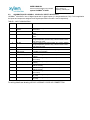
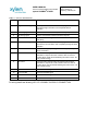
1
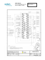
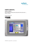
User’s Manual
Logimac 210/220 – PLC based control with up to 4 floats
210/220
USER’S MANUAL
of the PLC-based duplex pump control
system LOGIMAC® 210/220
Page: 2 of 20
Date: February 12
Replacing: February 09
System general characteristics
LOGIMAC® 210/220 (P/N 13-50 90 69) is a control system with the programmable logic controller
(PLC), which has been programmed especially for the operation and surveillance of stations
containing two submersible FLYGT pumps (duplex pump station). A level control is based on 3
(LOGIMAC® 210 sequence) or 4(LOGIMAC® 220 sequence) float signals (level switches).
The control system accomplishes the following basic functions (without being limited to it):
•
allows a choice between LOGIMAC® 210 and 220 sequences
•
controls the two pumps start - stop sequence
•
alternates the duty pump after each cycle of operation,
•
detects and diagnoses fault conditions of the pumps and of the level sensors,
•
puts into service the standby pump if the duty pump is in fault,
•
Identifies the degree of urgency between all fault-conditions and classifies them as FAULTS or
EMERGENCY.
1.1 Part numbers and reference drawing
Programmable logic controller LOGIMAC® 210/220VM-PLC : P/N 13-50 90 70
Alarm annunciator LOGIMAC® 220/210-AP--------------------: P/N 13-50 90 12
© Copyright 1995 ITT Flygt
®
The LOGIMAC is registered mark of ITT Flygt. All rights reserved. No part of this manual may be reproduced or copied without the
written permission of ITT Flygt.
Page: 3 of 20
Date: February 12
Replacing: February 09
USER’S MANUAL
of the PLC-based duplex pump control
system LOGIMAC® 210/220
2. DETAILED SPECIFICATION
2.1 LOGIMAC® 210/220-PLC CONFIGURATION and TECHNICAL DATA
:
ITEM #
DESCRIPTION
CPU & Memory
TECHNICAL DATA
Flash user memory
program memory: 6 Kwords
storage memory: 2 Kwords
operation speed:
logic
1.0 ms/ 1Kword of
user program: L221VM
P/N
16 - inputs
24V DC; current consumption: 7.3mA
max./point
11 relays+1 DC -outputs
operating.voltage: 5-30 V DC
13-50 90 70
5-250 V AC max. load:
2A resistive/ 0.6A ind.
Supply
120V AC ( 102 -132V), 60 Hz (47- 63
Hz)
DC output power supply: 24V + -10%,
200 mA max. current
Dimensions
(90H x 150W x76D) mm
service temperature
0..+55°C
stocking temperature
-40..+85°C
Port
Two serial ports:1: RS 232, 2: RS 485
Removable terminal strip
included
USER’S MANUAL
of the PLC-based duplex pump control
system LOGIMAC® 210/220
Page: 4 of 20
Date: February 12
Replacing: February 09
2.2.
ASSIGNATION OF LOGIMAC® 210/220-PLC INPUTS & OUTPUTS
LOGIMAC® 210/220-PLC has 16 digital inputs and 12 digital outputs (11 relays-based and 1 DC). For this application
the inputs and outputs are assigned to the signals specified in the table 1 and 2 respectively.
TABLE 1.: INPUT ASSIGNATION
INPUT
1
DESCRIPTION
2
ACKNOWLEDGE/
RESET
M1 contactor closed
3
M2 contactor closed
4
B1, R5
5
B2, R6
6
7
8
9
PFD
jumper or GEN SET
RUN contact
not used
FLL ( or ISRL) option
10
FLH- NO (or ISRH)
11
FLH- NC (or ISRH)
12
FL3
13
FL2
14
FL1
15
AUTO P1
16
AUTO P2
NOTES
signal provided by push button RESET on the alarm
annunciator
auxiliary contact of the M1 contactor to indicate the contactor
status
auxiliary contact of the M2 contactor to indicate the contactor
status
contact indicating overcurrent (breaker aux. contact), leakage
or high temperature (interface relay contact from Mini CAS II
unit ) of the P1 pump
contact indicating overcurrent (breaker aux. contact), leakage
or high temperature (interface relay contact from Mini CAS II
unit ) of the P2 pump
power failure detection (PFD)
to disable the parallel operation of two pumps;
LOGIMAC 210 operation
contact indicating the low level reached (follows FLL float NC
contact)
contact indicating the high level reached (follows FLH float
NO contact)
contact indicating the high level reached (follows FLH float NC
contact)
contact indicating the START 2 level reached (follows FL3
float NO contact)
contact indicating the START 1 level reached (follows FL2
float NO contact)
contact indicating the STOP level reached (follows FL1 float
NO contact)
contact indicating AUTO position of the mode selector of the
P1 pump
contact indicating AUTO position of the mode selector of the
P2 pump
For wiring details see drawing L221I/O: LOGIMAC 210/220 I/O CONNECTION
USER’S MANUAL
of the PLC-based duplex pump control
system LOGIMAC® 210/220
Page: 5 of 20
Date: February 12
Replacing: February 09
TABLE 2.: OUTPUT ASSIGNATION
OUTPUT
DESCRIPTION
NOTES
1
High Level alarm (option 3) The output of 24V DC, 0.75 A max. load, programmed as a
memorised High Level alarm. Use a separate LED for
indication.
2
M1 closing signal
order to close the M1 contactor (interface relay R1)
3
M2 closing signal
order to close the M2 contactor (interface relay R2)
4
EMERGENCY alarm
EMERGENCY alarm signal for remote transmission (interface
relay R14)
5
Low Level alarm (option 2)
The output of 120V AC, 2 A max. load, programmed as a
memorised Low Level alarm. Use a separate pilot light for alarm
indication.
6
EMERGENCY/FAULT
EMERGENCY signal (flashing ) and FAULT signal (stable) to
alarm annunciator
7
P1 FAULT
P1 FAULT alarm signal to alarm annunciator (this output is
activated if I4 input is ON or M1 contactor does not close its
contact during nine(9) seconds following the order to close - R1
relay contact closing)
8
P2 FAULT
P2 FAULT alarm signal to alarm annunciator (this output is
activated if I5 input is ON or M2 contactor does not close its
contact during nine (9) seconds following the order to close - R2
relay contact closing
9
FL1 FAILURE
FL1 float FAILURE signal
10
FL2 FAILURE
FL2 float FAILURE signal
11
FL3 FAILURE
FL3 float FAILURE signal
12
FLH FAILURE
FLH float FAILURE signal
For wiring details see drawing L221 I/O: LOGIMAC 210/220 I/O CONNECTION
USER’S MANUAL
of the PLC-based duplex pump control
system LOGIMAC® 210/220
2.3
PROGRAM DESCRIPTION
2.3.1
FLOAT FAILURE DETECTION
Page: 6 of 20
Date: February 12
Replacing: February 09
Programmable controller (PLC) assumes a continuous surveillance of the operating capabilities of all floats and their
electrical wiring.
Float failure detection is done during increasing and decreasing water level.
With a raising water level, the floats’ NO (normally open ) contact must close in sequence: FL1-FL2-FL3-FLH. If a
lower float does not close its contact (contact fails to close) before the higher float, the lower float will be declared
faulty.
With a water going down, the floats must open in sequence: FLH-FL3-FL2-FL1. If a lower float opens its NO contact
before a higher float, the higher float (or floats) will be declared faulty (its contact fails to open).
The float failure fault can not be acknowledged or reset using the RESET push button of the alarm annunciator.
To clear the float failure fault, the float contact must close, if it failed to close, or open, if it failed to open.
A level sensor failure is indicated on the alarm annunciator by one of 4 LED diodes labelled as “FL1 FAILURE”,
“FL2 FAILURE”, “FL3 FAILURE“,”FLH FAILURE” respectively
2.3.2.
FLOAT ASSIGNATION
Four (or three for Logimac 210 sequence) specific levels are assigned to floats FL1, FL2, FL3, and FLH during each
scan of program:
• STOP level
• START 1 level
• START 2 level (Logimac 220 sequence only)
• HIGH LEVEL alarm
Under normal circumstances (no float failure) the floats are assigned as follow:
•
•
•
•
FL1 - STOP level (stops two pumps)
FL2 - START 1 level (starts the duty pump)
FL3 - START 2 level (starts the standby pump; Logimac 220 sequence only)
FLH - water HIGH LEVEL alarm
If FL1 float fails with Logimac 220 sequence chosen, the operating floats will be assigned as follows:
•
•
•
•
FL1 - failure alarm(out of order)
FL2 - STOP level (stops two pumps)
FL3 - START 1 level (starts the duty pump)
FLH - START 2 level (starts the standby pump) and gives water HIGH LEVEL alarm
In Logimac 210 sequence START 2 is eliminated as well as the float FL3 and in this case the float FLH assumes the
START of the pump.
NOTE: See table 1 in appendices 1 for floats assignation in each specific case of the float failure for LOGIMAC 220
sequence and table 2 for LOGIMAC 210 sequence (float FL3 is not used).
2.3.3.
MODE OF OPERATION
A three-position MAN-OFF-AUTO operation mode selector is provided for each pump.
The AUTO position provides a completely automatic system operation.
If mode selector is placed in MAN position the respective pump will start without delay independently from level
detector conditions and requirements.
To stop this pump , put the mode selector in OFF position.
Either during manual or automatic operation the pumps stop automatically on fault condition.
USER’S MANUAL
of the PLC-based duplex pump control
system LOGIMAC® 210/220
2.3.4
Page: 7 of 20
Date: February 12
Replacing: February 09
CHOICE OF PUMP TO START
The control system allows an operation of either one pump only (Logimac 210 sequence ) or two pumps in
parallel ( Logimac 220 sequence) but prevents simultaneous start of two pumps.
In manual mode the pump with its mode selector placed in MAN position will start.
In automatic mode a choice of the pump to start is done by PLC program following the conditions specified below:
P1 PUMP is chosen to start as a duty pump if :
•
•
•
The start conditions are reached (water level is higher than START 1 level) and
P1 pump is operational (no faults) and its mode selector is in AUTO position , and
The P1 cycle of operation had not been memorised, or the P2 pump is faulty or its mode selector is not in
AUTO position.
P2 PUMP is chosen to start as a duty pump if :
•
•
•
The start conditions are reached (water level is higher than START 1 level) and
P2 pump is operational (no faults) and its mode selector is in AUTO position , and
The P1 cycle of operation had been memorised, or the P1 pump is faulty or its mode selector is not in
AUTO position.
P1 PUMP is chosen to start as a standby pump (to parallel operation with the duty pump) if :
•
•
•
•
The parallel operation is enable (no jumper on the input 7= Logimac 220 sequence)
The parallel operation conditions are reached (water level is higher than START 2 level) and
P1 pump is operational (no faults) and its mode selector is in AUTO position , and
M2 contactor is closed
P2 PUMP is chosen to start as a standby pump (to parallel operation with the duty pump) if :
• The parallel operation is enable (no jumper on the input 7= Logimac 220 sequence)
• The parallel operation conditions are reached (water level is higher than START 2 level) and
• P2 pump is operational (no faults) and its mode selector is in AUTO position , and
• M1 contactor is closed
Either start conditions or parallel conditions should be kept during at least 10-second period (START DELAY) to
start the pump.
USER’S MANUAL
of the PLC-based duplex pump control
system LOGIMAC® 210/220
2.3.5.
Page: 8 of 20
Date: February 12
Replacing: February 09
CONTACTOR OPERATION
In automatic mode the M1 contactor of the P1 pump (or the M2 contactor of the P2 pump) will close following the
closing signal from R1 (or R2) interface relay after START DELAY as specified in previous section.
Reception of closing confirmation by PLC is indicated by turning on the respective diode LED labelled RUN P1 or
RUN P2 on alarm annunciator (see appendices 2 for annunciator details).
NOTE: Closing fault: If PLC does not receive a confirmation of the closing (see M1 or M2 contact on PLC inputs I2,
I3) during a 9-second period following the closing order ( R1 or R2 relay closing contact), the closing signal will be
removed and alarm will be signalled. The LED diode EMERGENCY/FAULT on the alarm annunciator will turn on.
In automatic mode, if stop conditions are reached (STOP level) and are held during 1.5-second period, the running
pump contactors will open.
Each contactor can be opened or closed manually, using a mode selector ( MAN-OFF positions).
Either during manual or automatic operation the contactor opens automatically on fault condition of the respective
pump.
USER’S MANUAL
of the PLC-based duplex pump control
system LOGIMAC® 210/220
2.3.6.
Page: 9 of 20
Date: February 12
Replacing: February 09
ALARMS
2.3.6.1. ALARM: P1 / P2 OVERCURRENT
On an overcurrent fault the respective pump breaker opens. Auxiliary NC contacts of breaker status (B1, B2) are
used as overcurrent signals for PLC inputs.
If one of the contacts is closed (B1 or B2), alarm will be indicated by flashing LED diode (OVERLOAD P1 or
OVERLOAD P2) on the alarm annunciator, accompanied by the stable LED diode EMERGENCY/FAULT.
This alarm is not held or memorised in PLC memory but is maintained by the open pump breaker .
The contactor of the pump in fault will open automatically and can’t close without the operator’s intervention. Repair
the pump fault before closing the tripped breaker.
2.3.6.2. ALARM: WATER LEAKAGE OR HIGH TEMPERATURE OF P1/ P2 PUMP
The faults detection will be done by the sensors attached to Mini CAS II units of ITT Flygt. The interface relay of this
unit (R5 or R6) operates if a temperature of pump goes higher than sensor adjustment or water is detected in the
corresponding pump. The contacts of these relays are connected to PLC inputs to supply the information.
If one of these contacts is closed, the alarm WATER LEAKAGE/HIGH TEMPERATURE will be indicated by the
flashing LED diode ( LEAK./TEMP P1 or LEAK./TEMP P2) on the alarm annunciator, accompanied by stable LED
diode EMERGENCY/FAULT.
The high TEMP. alarm will be held (by Mini CAS II units), even if fault conditions disappear.
The LEAK. alarm is not held. It disappears with fault conditions disappearance.
The contactor of the pump in fault will open automatically and cannot be closed without operator’s intervention if a
fault is held (high TEMP.).
Reset the circuit after fault correction: push the RESET push button once for acknowledge (stop flashing) and twice
for reset. To reset a high TEMP. alarm push RESET Mini CAS push button first.
2.3.6.3. ALARM: HIGH WATER LEVEL
The faults detection will be done by FLH float. The normally open (NO) contact of the high level float (or ISRH) is
connected to PLC input.
If this contact is closed, a HIGH WATER LEVEL alarm will be memorised in PLC memory and will be indicated by
LED diode (HIGH LEVEL) on the alarm annunciator, accompanied by flashing LED diode EMERGENCY/FAULT.
The R14 relay will operate (its NO contact is available for transmission of EMERGENCY signal
remotely).
This alarm disappears with fault conditions’ disappearance.
To have this alarm indication memorised use the option 3 described on the next page.
2.3.6.4. ALARM: M1 / M2 Contactor Closing Fault
If a corresponding pump contactor does not close after 9-second delay initialised by the pump closing signal
(activation of the PLC output Q2 / Q3), the closing signal will be removed and the corresponding pump M1 or M2
contactor closing fault will be memorised in the PLC memory. The information to PLC is provided by the auxiliary
contact of the contactor status M1 or M2 (input I2 or I3)
The LED diode EMERGENCY/FAULT will light up.
This alarm is held and memorised in PLC memory. The outputs Q7 or Q8 will be activated (flashing).
Reset the circuit after fault correction: push the RESET push button on the alarm annunciator once for acknowledge
(stop flashing) and twice for reset.
USER’S MANUAL
of the PLC-based duplex pump control
system LOGIMAC® 210/220
Page: 10 of 20
Date: February 12
Replacing: February 09
2.3.6.5. ALARM: LOW WATER LEVEL (option1)
The faults detection can be done by FLL float (NC contact). The normally open (NO) contact of an interposing relay
ISRL should be connected to PLC input 9.
If this contact is closed, the LED diode EMERGENCY/FAULT will light up
This alarm will disappear with fault conditions’ disappearance.
2.3.6.6. ALARM: Memorised LOW WATER LEVEL (option 2)
If option 1 is used and if the red pilot light (LOW LEVEL) is connected to the output Q5 of the LOGIMAC-PLC the
LOW WATER LEVEL alarm will be memorised in PLC memory and will be indicated by this red pilot light (LOW
LEVEL) on the control panel, accompanied by LED diode EMERGENCY/FAULT on the alarm annunciator.
This alarm indication will be held even if the fault conditions disappear.
Reset the circuit after fault correction: push the RESET push button on the alarm annunciator once for acknowledge
(stop flashing) and twice for reset.
2.3.6.7. ALARM: Memorised HIGH WATER LEVEL (option 3)
If the red light (HIGH LEVEL) is connected to the 24VDC output Q1 of the LOGIMAC 210/220-PLC the HIGH
WATER LEVEL alarm be indicated by this red light on the control panel.
This alarm indication will be hold even if the fault conditions disappear.
Reset the circuit after fault correction: push the RESET push button on the alarm annunciator once for acknowledge
(stop flashing) and twice for reset.
2.3.7
EMERGENCY/FAULT SIGNAL
An EMERGENCY condition exists if :
-
high level sensor (float FLH) is activated or is faulty; or ,
both pumps have experienced at least one fault each or,
three (two for L210 sequence)or more floats failed
power phase failure is detected
In an EMERGENCY condition alarm :
- flashing LED diode EMERGENCY/FAULT is lit on the alarm annunciator ;
- R14 relay is activated (its NO contact is available for transmission of EMERGENCY signal
remotely).
Any fault condition other than an EMERGENCY condition is considered as FAULT and will be indicated by:
- turning on a corresponding alarm LED diode on the alarm annunciator, and
- turning on LED diode EMERGENCY/FAULT stable (no flashing)
NOTE: If FAULT signal is required for remote indication, connect an auxiliary relay R15 ( 24V DC.) to
EMERGENCY/FAULT PLC output Q6 in series with normally closed contact (NC) of R14 relay. Use a
contact of this relay as FAULT signal (see drawing L221 I/O for details)
USER’S MANUAL
of the PLC-based duplex pump control
system LOGIMAC® 210/220
Page: 11 of 20
Date: February 12
Replacing: February 09
2.3.8. ADDITIONNAL FEATURES ADDED IN THE PROGRAMMING
Version 1.2
FLOATS FAILURE RESET: the floats’ failure reset is possible using the RESET push button on the annunciator
panel, starting with this version of program.
The condition is, that the pumps were stopped by FL1 or FL2 float (float FL1 or FL2 is OK).
Version 1.3
LOW LEVEL ALARM BY-PASS DURING THE APF CLEANER OPERATION: The feature is applicable to the system
using low level float & APF cleaner. APF cleaner maintains pumps running until snoring (in order to clean a sump), so
without this feature at each APF cleaning cycle the low level alarm will appear.
This feature block the low level alarm appearance until the first normal float (FL1, FL2, FL3, and FLH) is tilted.
Version 1.4
LOW LEVEL FLOAT FAILURE DETECTION & BY-PASS:
Low level float as an alarm float stops al the pumps in order to protect the pumps (running without water can damage
pumps as well as pipes’ system)
Being the lowest float in the sump, the low level float can be trapped in solids so the control system can be blocked
under a low level condition. This version of program includes the detection of that kind of situation.
The detection of Low Level Float failure (low level float trapped) is made by the activation of one of the higher floats
(FL1, FL2, FL3, and FLH). Once the FLL failure detected the system lock is removed and the pumps can operate.
The FLL is back to the system (FLL failure is reset) at the and of pumping cycle (all upper floats OFF) or at any
moment if the float is liberated from solids (is flipped).
Version 1.5
MAXIMUM RUN TIME OF ONE PUMP
When only one pump is running during period of 2 consecutive hours it will be stopped and the other pump will start if
the start condition still exists. It is applicable only if the other pump is available.
Version 1.6
LOW LEVEL FLOAT FAILURE DETECTION & BY-PASS only with High Level float:
The detection of Low Level Float failure (low level float trapped) is made by the activation of High level float only
(FLH). Once the FLL failure detected the system lock is removed and the pumps can operate.
The FLL is back to the system (FLL failure is reset) at the and of pumping cycle (all upper floats OFF) or at any
moment if the float is liberated from solids (is flipped).
Version 1.8
One pump failure added to Emergency Alarm if simplex operation.
USER’S MANUAL
of the PLC-based duplex pump control
system LOGIMAC® 210/220
Page: 12 of 20
Date: February 12
Replacing: February 09
2.4
ALARM ANNUNCIATOR LOGIMAC® 220/210-AP (P/N 13 - 50 90 12).
2.4.1
TECHNICAL DATA :
Supply voltage: 24V DC
Current consuming: 80 mA.max.
2.4.2
COMPONENTS and THEIR FUNCTIONS:
The annunciator is composed of four (4 ) integrated parts:
•
Printed circuit board (P/N 13-50 90 07)
•
Face plate with descriptions (P/N 13-51 15 37)
•
Board connector with terminal (P/N 13-42 00 03)
•
Flat cable (P/N 13-41 00 15)
The printed circuit board
contains:
•
•
•
•
represents the circuit as per drawing 2603-A2 (see appendices 2). The circuit
13 diodes LED ( D1..D13),
2 push buttons (SW1et SW2),
13 resistors (R1..R13) to limit a current and
26 auxiliary diodes of type 1N4004 (D14.. 39).
Each parallel circuit (total 16 circuits) is connected to one pin (1-16) of the (P1) plug for flat cable connection.
The functions of circuit are :
Indication:
The positive(+) signal of 24V DC power supply connected to terminal 2 is common for all diodes LED. To
turn on one diode LED, the negative (-) signal should be connected to another end of circuit. It will be done if
the PLC output relay contact, connected to the specific LED circuit closes (All PLC outputs connected to
annunciator should have the common terminal COM connected to negative( - ) terminal of source).
USER’S MANUAL
of the PLC-based duplex pump control
system LOGIMAC® 210/220
Page: 13 of 20
Date: February 12
Replacing: February 09
Lamp test:
The negative (-) signal of 24V DC power supply connected to terminal 1 is used to test LED diodes. Pushing
the push button SW1, connect 24V DC power supply to all LED diode circuits and turn all LED’s on.
Acknowledge/Reset:
Pushing the push button SW2, the positive (+) signal of 24V DC power supply will be connected to PLC input
being connected to terminal 4 of the annunciator.
This input signal is programmed in PLC as acknowledge signal (first appearance) and as reset signal
(second appearance).
It is important to connect the common terminal COM of this PLC input to negative
( - ) terminal of source.
Face plate is a two-side lamicoid plate, with descriptions in English on the one side and in French on the
another one. The descriptions are as per drawing C-51 15 37
(see appendices 2).
Board connector with terminal is composed of 16 screw-terminals connected to a
16-pin male plug (P2) for a flat cable.
The flat cable is a 2-meters length cable with a female-plug on each end, which can be plugged in:
• P1 plug (on the printed circuit board) et
• P2 plug ( on the board connector with terminal).
USER’S MANUAL
of the PLC-based duplex pump control
system LOGIMAC® 210/220
Page: 14 of 20
Date: February 12
Replacing: February 09
APPENDICE 1
TABLE 1. ASSIGNATION OF FLOATS for LOGIMAC 220 sequence.
faulty
float (s)
NONE
FUNCTION
FLOAT 1
FUNCTION
FLOAT 2
FUNCTION
FLOAT 3
STOP
START 1
(stops two pumps) (starts duty pump)
START 2
(starts standby
pump)
STOP
START 1
(stops two pumps) (starts duty pump)
FLOAT 1
OUT OF ORDER
FLOAT 2
STOP
(stops two pumps)
FLOAT 3
STOP
START 1
(stops two pumps) (starts duty pump)
OUT OF ORDER
FLOAT 4
STOP
START 1
(stops two pumps) (starts duty pump)
FLOATS
1&2
OUT OF ORDER
OUT OF ORDER
START 2
(starts standby
pump)
STOP
(stops two pumps)
FLOATS
1&3
OUT OF ORDER
STOP
(stops two pumps)
FLOATS
1&H
OUT OF ORDER
FLOATS
2&3
STOP
(stops two pumps)
STOP
START 1& 2
(stops two pumps) (starts two pumps)
OUT OF ORDER
OUT OF ORDER
FLOATS
2&H
STOP
(stops two pumps)
OUT OF ORDER
OUT OF ORDER
START 1
(starts duty pump)
OUT OF ORDER
START 1& 2
(starts two pumps)
OUT OF ORDER
FUNCTION
FLOAT H
INDICATION
HIGH LEVEL
alarm
NONE or
EMERGENCY if
FLH active
HIGH LEVEL
alarm &
START 2 (starts
standby pump)
HIGH LEVEL
alarm &
START 2 (starts
standby pump)
HIGH LEVEL
alarm &
START 2 (starts
standby pump
OUT OF ORDER
FAULT or
EMERGENCY if
FLH active
HIGH LEVEL
alarm &
START1&2
(starts two pumps)
HIGH LEVEL
alarm &
START1&2
(starts two pumps)
OUT OF ORDER
FAULT or
EMERGENCY if
FLH active
HIGH LEVEL
alarm &
START1&2
(starts two pumps)
OUT OF ORDER
FAULT or
EMERGENCY if
FLH active
STOP
START 1& 2
OUT OF ORDER
FLOATS
3 ET H
(stops two pumps) (starts two pumps)
3 FLOATS TWO PUMPS START AND KEEP RUNNING UNTIL FAULT CORRECTION
or MORE
FAULT or
EMERGENCY if
FLH active
FAULT or
EMERGENCY if
FLH active
EMERGENCY
FAULT or
EMERGENCY if
FLH active
EMERGENCY
EMERGENCY
EMERGENCY
EMERGENCY
USER’S MANUAL
of the PLC-based duplex pump control
system LOGIMAC® 210/220
Page: 15 of 20
Date: February 12
Replacing: February 09
TABLE 2. ASSIGNATION OF FLOATS FOR LOGIMAC 210 SEQUENCE
faulty
float (s)
NONE
FLOAT 1
FLOAT 2
FLOAT H
FUNCTION
FLOAT 1
STOP
(stops
pump)
OUT OF
ORDER
STOP
(stops
pump)
FUNCTION
FLOAT 2
START
(starts duty
pump)
STOP
(stops
pump)
OUT OF
ORDER
FUNCTION
FLOAT H
INDICATION
HIGH LEVEL
alarm
NONE or
EMERGENCY if
FLH active
HIGH LEVEL
alarm &
START
starts duty pump
HIGH LEVEL
alarm &
START
starts duty pump
OUT OF ORDER
FAULT
EMERGENCY if
FLH active
STOP
START
(stops
(starts duty
pump)
pump)
ONE PUMP START AND KEEP RUNNING UNTIL
2 FLOATS
or MORE FAULT CORRECTION
FAULT
EMERGENCY if
FLH active
EMERGENCY
EMERGENCY
USER’S MANUAL
of the PLC-based duplex pump control
system LOGIMAC® 210/220
Page: 16 of 20
Date: February 12
Replacing: February 09
APPENDICE 2
List of attached drawings:
1. Drawing # 2603-A2 : Alarm annunciator, printed circuit and interconnection schematic
2. Drawing # C-51 15 37: LOGIMAC® 220/210-AP Alarm annunciator, face plate with descriptions
3. Drawing # L221 I/O : LOGIMAC 210/220 INPUT/OUTPUT CONNECTION
USER’S MANUAL
of the PLC-based duplex pump control
system LOGIMAC® 210/220
Page: 17 of 20
Date: February 12
Replacing: February 09
USER’S MANUAL
of the PLC-based duplex pump control
system LOGIMAC® 210/220
Page: 18 of 20
Date: February 12
Replacing: February 09
USER’S MANUAL
of the PLC-based duplex pump control
system LOGIMAC® 210/220
Page: 19 of 20
Date: February 12
Replacing: February 09
USER’S MANUAL
of the PLC-based duplex pump control
system LOGIMAC® 210/220
Page: 20 of 20
Date: February 12
Replacing: February 09
www.xylemwatersolutions.com/ca
Pointe-Claire, QC, Tel.: (514)695-0133 • Saint-Augustin-de-Desaures, QC, Tel.: (418)878-1800
• Val d’Or, QC, Tel.: (819)825-0792•Coquitlam, BC, Tel.: (604) 941-6664 • Calgary, AB, Tel.: (403) 279-8371
Edmonton, AB, Tel.: (780) 489-1961•Saskatoon, SK, Tel.: (306) 933-4849 • Winnipeg, MB, Tel.: (204) 235-0050
•Toronto, ON, Tel.: (416) 679-1199 •Ottawa, ON, Tel.: (613) 225-9600 • Sudbury, ON, Tel.: (705) 560-2141
•Moncton, NB, Tel.: (506) 857-2244 • Halifax, NS, Tel.: (902) 450-1177 • St. John’s, NL, Tel.: (709) 722-6717.