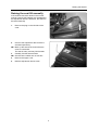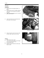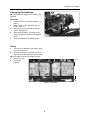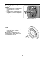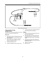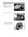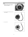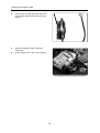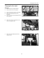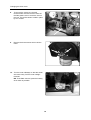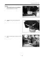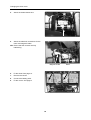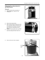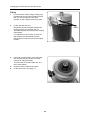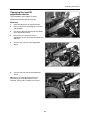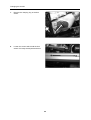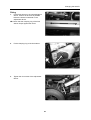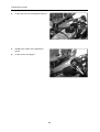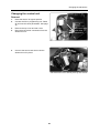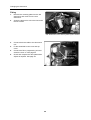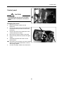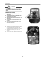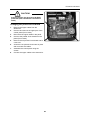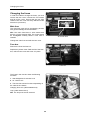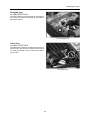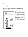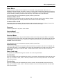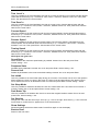
1
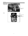
SERVICE MANUAL
Chairman Robo PG8
US
SERVICE MANUAL
Chairman Robo PG8
Produced and published by Permobil AB, Sweden
Edition no. 1, 9905
Order no.: 201019-US-0
PAB no.: 1019:1
Contents
Introduction .....................................................................................................5
Technical support.........................................................................................5
Spare parts ..................................................................................................5
Warranties....................................................................................................5
Maintenance ................................................................................................5
Rating plates ...................................................................................................6
Chairman Robo............................................................................................6
Panel............................................................................................................6
Raising the seat lift.........................................................................................7
Covers..............................................................................................................8
Removal.......................................................................................................8
Fitting ...........................................................................................................8
Changing the batteries...................................................................................9
Removal.......................................................................................................9
Fitting ...........................................................................................................9
Changing the drive wheel ..............................................................................10
Removal.......................................................................................................10
Fitting ...........................................................................................................10
Changing the brake release wires ................................................................11
Changing the magnetic brake .......................................................................12
Removal.......................................................................................................12
Fitting ...........................................................................................................13
Changing the drive motor..............................................................................15
Removal.......................................................................................................15
Fitting ...........................................................................................................17
Changing the carbon-brush in the drive motor...........................................19
Removal of the carbon-brush ......................................................................19
Fitting the carbon-brush...............................................................................20
Changing the seat lift adjustment device ....................................................21
Removal.......................................................................................................21
Fitting ...........................................................................................................23
Changing the control unit..............................................................................25
Removal.......................................................................................................25
Fitting ...........................................................................................................26
Changing the control panel ...........................................................................27
Changing the joystick ....................................................................................28
Changing the printed circuit board...............................................................29
Changing the fuses ........................................................................................30
Main fuse .....................................................................................................30
Fuses in the fuse box ..................................................................................30
Charging fuse ..............................................................................................31
Cable fuse....................................................................................................31
DP1c programming unit .................................................................................32
Error codes......................................................................................................36
Wiring diagram................................................................................................37
4
Inledning
Introduction
The Service Manual is intended for technical personnel who maintain and repair electric wheelchairs.
It is important that anyone who performs maintenance and repairs described in this manual reads and
understands the content of this manual so that the work is performed professionally. Always state the
chassis number when contacting Permobil to ensure that the correct information is provided.
Technical Support
In the event of Technical Problems, you should contact your dealer, or Pemobil Inc at 800-736-0925
Spare parts
Spare parts must be ordered through your dealer.
The spare parts catalogue for the Chairman Basic chassis is PAB 1212 and is available from Permobil
Inc.
Warranties
Contact your nearest dealer or Permobil Inc. for information on the current warranties.
Maintenance
See the information in the Owner’s Manual.
Reconditioning
Contact Permobil Inc. for Reconditioning Instructions.
5
Rating plates
Rating plates
Chairman Robo
Identity marking
Chassis no.
Panel
Identity marking
Art. no.
Serial no.
Modification no.
6
Raising the seat lift
Raising the seat lift manually
If the seat lift cannot be raised in the normal
manner because the batteries are discharged or
the adjustment device is defective, the seat can
be raised manually.
1.
Remove the plug on the left side of the
cover.
2.
Unscrew the adjustment device with the
enclosed special key.
NB. Block up the seat at the front before the
screw is unscrewed.
The seat is heavy and may fall forwards.
3. Carefully fold the seat forwards.
NB. Check that the cables are not too taut.
4. Remove the upper cover.
5. Refit the adjustment device screw.
7
Covers
Covers
Removal
1.
2.
3.
4.
Raise the seat to its highest position, se
page 7.
Remove the top cover. It is held in place by
Velcro tape, so it just needs to be pulled
upwards.
Then remove the chassis cover. It is held in
place by four screws.
Open the electronics box and disconnect
the contact for the rear light.
Contact for rear light
5.
Finally, remove the two front covers. They
are each held in place by two screws.
Fitting
1.
2.
3.
4.
First fit the two front covers.
Then reconnect the cable for the rear light
and close the electronics box.
Fit the chassis cover.
Refit the top cover. Press the Velcro tape
firmly in place.
8
Changing the batteries
Changing the batteries
NB. Use protective goggles when working with
batteries.
Removal
1.
2.
3.
4.
5.
Raise the seat to its highest position., se
page 7.
Remove the covers. See removing the
covers, page 7.
Remove the rear cover and the battery
covers. See page 8.
Disconnect all battery connections, the
positive poles first and then the negative
poles.
Lift out the batteries. Use lifting straps.
Fitting
1.
Insert two new batteries. The battery poles
must be at the back.
2. Connect the battery connections, first the
negative poles and then the positive poles.
NB. The cables must be connected correctly.
3. Refit the covers.
4. Charge the
batteries.
Plus +
Front
Minus -
Plus +
Minus -
rear
Battery connections
9
Changing the drive wheel
Changing the drive wheel
Removal
1.
2.
3.
Raise and block up the wheelchair's chassis
so that the wheel does not reach the
ground.
Loosen and remove the center screw C, the
washer B and the rim locking washer A (see
the figure at the bottom of the page).
Pull the wheel off the axle. Use the removal
tool 304103-99-0 if the wheel cannot be
removed by hand.
Removal tool 304103-99-0
Fitting
1.
2.
Fit the wheel onto the axle.
Fit the rim locking washer A, the washer B
and the center screw C and tighten to
secure the wheel.
NB. The screw has a locking coating which is
sufficient for refitting 3-4 times. Then the screw
must be replaced with a new one.
10
Changing the brake release wires
2
1
Brake release mechanism
Changing the brake
release wires
5.
The upper wire controls the left brake unit and the
lower wire controls the right brake unit.
Fitting
Removal
1.
2.
Raise the seat lift to its highest position (use
the crank provided for chairs without a seat
lift), see page 7.
Remove the cover, see page 8. Move the
brake release lever forwards to its front
position to facilitate removal.
Loosen the wire at the magnetic brake and
at the brake release mechanism.
1.
Fit the wire first at the magnetic brake and
then at the release lever.
2.
Adjust the length of the wire sleeve using
the adjusting screw (2) so that the wire is
tensioned but does not pull on the release
clamp.
3.
Check that the brake works. Release the
brake with the release lever and check that
the wheel can turn.
3.
Loosen the locking nut (1).
4.
Tighten the locking nut.
4.
Screw the adjusting screw (2) all the way in.
5.
Refit the cover.
11
Changing the magnetic brake
Changing the magnetic brake
Removal
1.
2.
3.
Raise the seat to its highest position.
Remove the covers. See page 8.
Disconnect the electrical connection of the
magnetic brake.
Electrical connection of the magnetic brake
4.
Detach the brake release wire from the
brake.
5.
Unscrew the three screws which hold the
brake and remove the brake with the
extensible cover, brake disc and cover.
Note the position of the brake release arm.
6.
12
Changing the magnetic brake
Fitting
1.
Check the setting of the brake. Follow the
instructions on the decal on how the two
Allen screws are adjusted.
2.
Place the magnetic brake's brake disc in the
brake assembly.
3.
Put on the cover.
13
Changing the magnetic brake
4.
Insert a screw to align the parts and screw
the magnetic brake in place using all three
screws.
5.
Attach the magnetic brake's electrical
connection.
Fit the chassis cover. See Covers, page 8.
6.
The magnetic brake's electrical connection
14
Changing the drive motor
Changing the drive motor
Removal
1.
2.
Raise the seat to its highest position.
Remove all the covers. See page 8.
3.
4.
Remove the positive pole from one battery.
Block up the appropriate side of the
wheelchair.
Remove the wheel. See Changing the drive
wheel, page 10.
5.
6.
Detach the electrical connections for the
motor and magnetic brake.
Magnetic brake
7.
Detach the brake release wire from the
magnetic brake.
15
Motor
Changing the drive motor
8.
To remove the motors, the chassis
reinforcement must be removed. Take off
the little plastic cover to reach the nuts on
the rear. The reinforcement is held in place
by four screws.
9.
Remove the three screws which hold the
motor.
10. Turn the motor sideways so that the wheel
axle turns freely. Pull the motor straight
forwards.
NB. To facilitate removal, press the battery
as far back as possible.
16
Changing the drive motor
Fitting
1.
Lift the motor into place. Turn it a little so
that the wheel axle can turn freely without
being obstructed by the chassis.
2.
Screw the motor in place with the three
screws.
3.
Refit the chassis support. Press the cover in
place.
17
Changing the drive motor
4.
Attach the brake release wire.
5.
Attach the electrical connections for the
motor and magnetic brake.
NB. Ensure that the contacts are fully
interlocking.
Magnetic brake
6.
Fit the wheel. See page 10.
7.
Remove the blocks.
8.
Connect the battery poles.
9.
Fit the covers. See page 8.
18
Motor
Changing the carbon-brush in the drive motor
Changing the carbon-brush in
the drive motor
Removal
1.
2.
Remove the drive motor. See page 15.
Remove the motor's cables from the
coupling box.
3.
4.
Remove the magnetic brake.
Mark the stator's position against both ends
with a small mark before loosening the nuts.
It is important for the function of the motor
that the parts are assembled precisely
without being moved away from the original
position.
Loosen two nuts and pull off the motor end.
Press the cable gland off the motor end.
5.
6.
Remove the brush holder completely.
Do not
divide
here
19
Marking
Changing the carbon-brush in the drive motor
Fitting
1.
Fit a new brush holder using the fitting ring
provided with the new brush holder. Ensure
that you turn the cables in the same
direction as the outgoing shaft of the gear.
2.
Fit the end with two nuts.
Remember the wave washer between the
bearing and the end. Ensure that you
assemble the parts according to the marking
made earlier.
It is important for the function of the motor
that the parts are assembled precisely
without being moved away from the original
position.
3.
4.
5.
Marking
Insert the mounting plate, cover and brake
disc. Ensure that you position the holes
correctly for fitting the brake.
Turn the brake so that the brake arm is in
the correct position.
Screw the motor cables to the plinth.
Fit the drive motor. See page 17.
20
Changing the seat lift
Changing the seat lift
adjustment device
The procedure is the same for both
adjustment devices for the seat lift.
Removal
1.
Raise the seat lift to its highest position.
2.
Remove all covers. See page 8. Lower the
seat lift again.
3.
Cut off the cable ties which hold the cables
to the adjustment device.
4.
Disconnect the connections to the
adjustment device. Note how the cables are
attached.
5.
Unscrew the rear bolt of the adjustment
device.
6.
Unscrew the front bolt of the adjustment
device.
NB. Work on the left adjustment device is
facilitated if you manually push the chair
forwards. Check that no cables are too taut.
21
Changing the seat lift
7.
Remove the clamping ring of the limit
switch.
8.
Loosen the screws which hold the limit
switch. Pull away the adjustment device.
22
Changing the seat lift
Fitting
1.
Fit the limit sleeve on the new adjustment
device. Press it as far back as possible
before the sleeve is fastened on the
adjustment device.
NB. Check that the clamping ring of the limit
sleeve clamps against the frame.
2.
Fit the clamping ring of the limit sleeve.
3.
Tighten the front screw of the adjustment
device.
23
Changing the seat lift
4.
Fit the rear screw of the adjustment device.
5.
Reattach the cables of the adjustment
device.
6.
Fit the covers. See page 8.
24
Changing the electronics
Changing the control unit
Removal
1.
2.
3.
4.
5.
Raise the seat to its highest position.
Connect the DP1c programming unit. Read
off and note the drive parameters. See page
32.
Remove the top cover and rear cover.
Disconnect the power connections from the
electronics unit.
Disconnect these
three cable
connections
Unscrew the two screws which hold the
electronics unit in place.
The electronics unit is held in place by two screws
25
Changing the electronics
Fitting
1.
2.
Remove the mounting plate from the old
electronics and mount it on the new
electronics.
Screw the electronics unit to the frame with
the two screws.
The electronics unit is held in place by two screws
3.
4.
5.
6.
Connect the three cable to the electronics
unit.
Fit the wheelchair's rear cover and top
cover.
Connect the DP1c programming unit and
switch the chair on. See page 32
Check and compare the drive parameters.
Adjust as required. See page 32.
Connect these
three cable
connections
26
Control panel
Control panel
CAUTION!
Anyone opening the panel must be ESDprotected (with a wristband connected to
earth).
Changing the panel
1.
Remove the upper cables from the
electronics.
2. Unscrew and remove the control panel from
the panel bracket (two Allen screws under
the panel).
3. Unscrew and remove the upper part of the
control panel (four screws).
4. Disconnect the upper cables in the panel.
5. Open the new panel and connect the upper
cables.
6. Assemble the panel and screw it to the
panel bracket.
NB! The panel cover and base cover are marked
with ID numbers and modification numbers
and belong together
7. Connect the upper cables to the electronics.
27
Control panel
CAUTION!
Anyone opening the panel must be ESDprotected (with a wristband connected to
earth).
Changing the joystick
1.
2.
3.
4.
5.
6.
7.
8.
Remove the upper cables from the
electronics.
Unscrew and remove the upper part of the
control panel (four screws).
Disconnect the joystick connection from the
electronics.
Unscrew the two mounting screws of the
joystick.
Pull out the joystick ball and then remove
the whole mechanism.
Screw the new joystick in place and connect
it to the printed circuit board. Turn the
joystick so that the pointed side is to the left.
Assemble the control panel using the
screws.
Connect the upper cables to the electronics.
28
Printed circuit board
CAUTION!
Anyone opening the panel must be ESDprotected (with a wristband connected to
earth).
Changing the printed circuit board
1.
2.
3.
4.
5.
6.
7.
8.
Remove the upper cables from the
electronics.
Unscrew and remove the upper part of the
control panel (four screws).
Disconnect the upper cables in the panel.
Unscrew the printed circuit board from the
panel (four screws).
Remove the old printed circuit board and fit
a new one.
Screw the new printed circuit board in place
and reconnect the cables.
Assemble the control panel using the
screws.
Connect the upper cables to the electronics.
29
Changing the fuses
Changing the fuses
In order to be able to change the fuses, you must
remove the rear cover. Unscrew the five screws
and lift off the cover. Ensure that the rear light
cables in the rear cover are firmly attached to the
electronics (connector).
Main fuse
The main fuse must only be changed by persons
with good knowledge of the wheelchair.
NB. If the main fuse blows, it often means that
there is a major electrical fault. The cause should
be investigated carefully before a new fuse is
inserted.
80 A main fuse
Change the main fuse and refit the rear cover.
Fuse box
Remove the lid of the fuse box.
Replace any blown fuses. Refit the lid of the fuse
box, refit the rear cover and screw it in place.
Fuse box
The fuses in the fuse box have the following
functions:
1
2
3
1. Seat lift/lights/24 V switched 15 A
2. 24 V direct 15 A
3. This fuse has various functions depending on
the cable in the chassis.
Charging fuse 15 A (cable 306858-00-0)
Loop (cable 308737-00-0)
NB. The loop must not be removed.
Fuses
30
Changing the fuses
Charging fuse
on cable 308737-00-0
The fuse holder for the charging fuse is placed on
the narrow red cable which goes to the positive
pole of the battery.
15 A charging fuse
Cable fuse
on cable 308737-00-0
The cable fuse protects the cable in the event of a
short-circuit in the contact. If this fuse blows, there
is a faulty connection in the contact in the card in
the fuse box.
20 A cable fuse
31
DP1c programming unit
Connection
1. Switch off the chair.
2. Connect the DP1c to the socket beside the charging socket on the left side of the
chair.
3. Switch on the chair.
NB. The seat lift must be in its lowest position for the instrument to work.
The instrument
DP1c
The arrow keys are used to step to
the various programming positions
and to make the necessary changes
in these positions.
Custom Programmer
(For use with Permobil wheelchairs only)
The ? key can be used to obtain help
in the respective programming
positions.
Enter
is
used
to
confirm
programming and to jump to
programming positions from the
menu.
?
The Traffic Light is used to prepare
the chair for driving/testing.
Yes
No
Enter
Penny+Giles
32
DP1c programming unit
Root Menu
When the chair is switched on and the DP1c is connected, driving is blocked. "DP1c Vn.n" is
displayed in the text window of the DP1c, where n.n is the version number of the program in the DP1c
in question. Then the Chairman 8 LS menu position is displayed. It is now possible to step through the
various menus by pressing on either of the arrow keys. The menus in the root menu are:
To go from the menu to the respective program positions, press Enter.
Chairman Robo 8 LS
Downloads all the parameters which a Chairman with Leroy Somer motors had on delivery. Answer
Yes or No and press Enter. These parameters will now be the new basic settings.
Chairman Robo 8 GS
Downloads all the parameters which a Chairman with Grosshop motors had on delivery. Answer Yes
or No and press Enter. These parameters will now be the new basic settings.
Reserved
2 reserve positions for any future chair models.
Service Menu?
Jump to the service menu.
Service Menu
To enter the service menu, step to Service Menu? with the arrow keys and press Enter. It is possible
to step through the service menu using the arrow keys as in the root menu. The service menu is used
to set special drive parameters for a user and to read/erase the fault log. The following positions are
available in the service menu:
To go from the menu to the respective program positions, press Enter.
Read Fault Log
In the fault log it is possible to read off the alarms which have occurred in the chair. For example, this
may appear as follows: 1:Code 3B00#5. This means that fault 3B00 has occurred 5 times in the chair
and the most recent type of fault was 3B00 = Cable break left drive motor. To return to the menu,
press Enter.
Erase Fault Logg
It is possible to erase the fault log here. Answer Yes or No and press Enter.
Acceleration
Here it is possible to set how fast/slowly the chair is to accelerate. Set the desired value with the arrow
keys, up = increase in value, down = reduction, between 0 and 100. Then press Enter. See the table
for the normal value.
Deceleration
Here it is possible to set how fast/slowly the chair is to brake. Set the desired value with the arrow
keys, up = increase in value, down = reduction, between 0 and 100. Then press Enter. See the table
for the normal value.
33
DP1c programming unit
Turn Accel´n
Here it is possible to set how fast/slowly the chair is to reach the maximum turn speed. Set the desired
value with the arrow keys, up = increase in value, down = reduction, between 0 and 100. Then press
Enter. See the table for the normal value.
Turn Decel´n
Here it is possible to set how fast/slowly the chair is to stop turning. Set the desired value with the
arrow keys, up = increase in value, down = reduction, between 0 and 100. Then press Enter. See the
table for the normal value.
Forward Speed
Here it is possible to set the maximum and minimum forward speeds. Set the desired value with the
arrow keys, up = increase in value, down = reduction, between 0 and 100. Then press Enter. See the
table for the normal value.
Reverse Speed
Here it is possible to set the maximum reverse speed. The minimum speed is calculated from the
forward speed. Set the desired value with the arrow keys, up = increase in value, down = reduction,
between 0 and 100. Then press Enter. See the table for the normal value.
Turning Speed
Here it is possible to set the maximum and minimum turning speeds. Set the desired value with the
arrow keys, up = increase in value, down = reduction, between 0 and 100. Then press Enter. See the
table for the normal value.
NB. Adjust with great care.
Speed State
States whether the maximum speed setting is possible. Answer Yes or No and press Enter.
Normal setting = Yes.
Response State
Possible future parameters. Answer Yes or No and press Enter. Normal setting = No.
Present Unit
Resets all parameters to the most recent basic settings. Answer Yes or No and press Enter.
Set Inhibit
Here it is possible to set how inhibit (stop driving) is to function. First answer Yes or No to the question
about whether the chair is to stop in the event of a short-circuit and press Enter, then answer Yes or
No to whether there is be an alternate function for inhibit and press Enter. Normal setting = No/No.
Set Sleep Mode
Here it is possible to determine whether the chair is to switch itself off if it is inactive for more than 5
minutes. Answer Yes or No and press Enter. Normal setting = No.
Park Brake Trip
Here it is possible to set whether the chair is to sense the magnetic brakes. Answer Yes or No and
press Enter. Normal setting = Yes.
Set Steering
Straight trim. Trim with the arrow keys: arrow up (+) = trim to the right, arrow down (-) = trim to the left.
Press Enter to confirm the trim. Applies from V4 of the electronics.
Show Settings
Shows all settings which have been made. Press Enter again to exit the display.
Back to Root
Return to the root menu.
34
DP1c programming unit
Preprogrammed values
Value
Chairman Robo 8 LS
Chairman Robo 8 GS
Acceleration
50
50
Deceleration
70
70
Turn Accel´n
15
20
Turn Deccel´n
28
25
Forward Speed
90/30
100/30
Reverse Speed
42
60
Turning Speed
25/10
25/8
Speed State
Yes
Yes
Response State
No
No
Set Inhibit
No/No
No/No
Set Sleep Mode
No
No
Part Brake Trip
Yes
Yes
Enter
Dp1c V1.2 var0
entering menu...
Back to root
Show
Settings
Set
Steering
Part brake
Trip
Set Sleep
Mode ?
Enter
Chairman 8
LS
Service
Menu?
Read Fault
Log
Set Inhibit
Chairman 8
GS
Reserved
Erase Fault
Log
Present Unit
Hexior 8 LS
Reserved
Acceleration
?
Response
State
Deceleration
?
Speed State?
Turn Accel´n
?
Turn
Decel´n
?
35
Forward
Speed
Reverse
Speed
Turning
Speed
Battery indicator
Battery indicator
– Battery indicator flashes fast..
A fault has occurred and the wheelchair will not
work. The number of flashing lights indicates the
nature of the fault.
– Note the number of flashing lights.
– Switch off the wheelchair.
– Switch the wheelchair back on.
– Check whether the fault is still present.
The battery indicator indicates the status of the
wheelchair.
– Battery indicator lights permanently
This indicates that everything is OK.
– Battery indicator flashes slowly.
This indicates that the battery should be
charged as soon as possible.
Troubleshooting
If a fault occurs in the wheelchair, a number of lights flash on the battery voltage indicator. Count the number
of lights, starting from the joystick, and check in the list what the fault is and what you can do.
Number
of lights
Cause
Remedy
1
The charge level of the battery is
much too low. It requires
immediate charging
Check the condition of the battery to see whether it
needs replacing. Check the contact between the
battery and the control unit.
2
There is an interruption to the left
motor.
Check the connection to the left drive motor.
Check whether the drive motor's carbon-brush is worn.
3
Short-circuit between the battery
and the drive motor.
Check the contacts and cables of the motor.
4
There is an interruption to the right
motor.
Check the connection to the right drive motor.
Check whether the drive motor's carbon-brush is worn.
5
Short-circuit between the battery
and the drive motor.
Check the contacts and cables of the motor.
6
Charger connected to charging
socket.
Remove the charging contact from the chair.
Joystick fault.
Ensure that the joystick is not affected by operation.
Check the contact between the joystick and the
control unit.
Replace the joystick unit.
Replace the joystick cables.
If the fault is still present, replace the control unit.
8
Control unit fault.
Check the contacts of the control unit.
If the fault is still present, replace the control unit.
9
Interruption in brake circuit.
Check the contacts of the magnetic brake.
Too high voltage in the battery
Check the battery and the contacts between the
battery and the control unit.
2
3
4
5
6
7
7
8
9
10
10
36
Green RK 4,0
White RK 4,0
Yellow RK 0,5
Brown RK 0,5
Battery pos
+24V
0
Red RK 6,0
Black RK 6,0
1
2
2
3
3
5
5
6
6
Red RK 6,0
7
7
8
8
9
9
Battery neg
24V Output
15A
20A
1
1
2
2
3
3
10
PG8 REMOTE DIGITAL CONTROLLER
Red RK 2,5
Green UL1569 AWG24
Black RK 2,5
2 3 4 5 6
2
16
Red RK 1,5
Green UL1061 0.56
Black RK 1.0
Red RK 1,5
Green UL1061 0.56
Black RK 1.0
- N
24V
1
2
Black RK 0.75
Violet RK 0.75
1
PCB SLS REDUCED 7192
CABLE CHARGE CONNECTOR 8737
INH D
1
2
15A
6
5
4
3
2
1
J4
3
2
0V
SEAT POS
INHIBIT
DATA
SER.OUT
+12
1
2
3
4
1
2
3
4
5
6
5
6
5 6
34 5
7
8
6 7
8
Brown
Red
Orange
Yellow
Green
Black
ACTU CONTROL SEAT LIFT
6422
1
1
15A
J10
2
1
Grey 0.75
Black RK 0.75
Orange RK 0.75
Blue 0.75
Red 0.75
J11
15A
Black 0.75
2
1
Blue RKKB 4x0.75
C
Grey RKKB 4x0.75
2
No Nc
1
Black Elcu mini 2x0,22
2
Brown Elcu mini 2x0,22
Actuator
1
2
1
2 3 4
+24V
No Nc
CABLE BRAKE TERRA 7135
Brown SKX 0.75
Blue SKX 0.75
CABLE BREAKPO
SEAT FUNC 6127
J7 1
C
1
2
1
2
J9
InhibitLow Speed
J5
2
1
+24V
0V
J4
J3
2
3
4
5
6
7
8
SW3
1
SW1
2
Red RKKB 4x0.75
Nc No
Green Elcuflex 0.22
No Nc
Blue FKUX 0.25
SW2
M
End
Plug 4
7
8
SW3
C
Orange FKUX 0.25
1
2
3
SW2
C
Black RKKB 4x0.75
Orange Elcuflex 0.22
5
6
C
Red Elcuflex 0.22
No Nc
Yellow Elcuflex 0.22
Brown Elcuflex 0.22
No Nc
SEAT LIFT ACTU
6422
SW3
ACTU TERRA
C
Black Elcuflex 0.22
M
SW4
6429
MEMBRANSWITCH 6061-3
RE2
SW1
C
3
T2
SW3
Brown RKKB 0.75
Yellow RKKB 0.75
Actuator
SW1
C
Nc No
+24V
CABLE ACTU CTR
24V 6319
Nc No
4
SW3
MEMBRANSWITCH ACTUATOR CONTROLLER 5954-10
+24V
SW4
SW2
SW5
PIN
RE1
4
1
2
2
3
4
3
4
K5
K7
3
4
K2
K4
K6
K8
5
6
5
6
5
7
8
9
7
8
9
7
8
9
10
10
(SW1)
RE4
5
1
2
RE3
Brown SKX 0.75
Blue SKX 0.75
4
J5
3
6
5
T3
5
K3
4
8
7
3
2
1
2
1
6
10
SIL1
CABLE ACTUATOR CONTR. 6743
CABLE ACTUATOR CONTR. 6743
(SW2)
4
K1
J2
2
3
T4
9
ACTU CONTROL TERRA
7134
+24V
IC1
1
5
PIN
10
Brown SKX 0.75
Blue SKX 0.75
J6
3
T1
+24V
1
1
2
J1
SIL2
1
5
SW1
2
2
3 4
CABLE PCB-ELECTRONIC 6851
12 3 4 5 6
5
4
J6
CABLE 24V OUTLET 7044
1 2 3 4 5 6
J3
6
1
2
Relay C
13
15
1 2
+ P
Charge plug
Brown RKKB 0.75
Blue RKKB 0.75
HA
Black RK 2.5
Red RK 2,5
1
12
Black UL1569 AWG24
Green UL1569 AWG24
CABLE PROGR SIDE PANEL 6852
Prog
11
7777
14
1
Brake switch
JOYSTICK
4
4
Fuse 80A
CONTROL PANEL L8 7199
1
1
2
Blue RK 4,0
Brown RK 4,0
Left motor
24V
CABLE LOWER 7699
Brown RK 0,5
Yellow RK 0,5
Left parkbrake
Brown Elcuflex 0.22
Black Elcuflex 0.22
RITHA
ACTUATOR CONTROLLER BOARD 7131-10
Blue Rk 0.75
Blue Rk 0.75
Black Rk 0.75
1
Black Rk 0.75
Red2.5
Black 2.5
1
M
M
Black 2.5
Red 2.5
2
RIGHT MOTOR
2
LEFT MOTOR
Wiring Diagram Robo S
SW4
K7
K8
SW2
K5
K6
SW3
K3
K4
SW1
K1
K2
Blue RKKB 4x0.75
Grey RKKB 4x0.75
Grey 0.75
Blue 0.75
Red 0.75
Black 0.75
Black Elcu mini 2x0,22
Brown Elcu mini 2x0,22
Black RKKB 4x0.75
Red RKKB 4x0.75
Orange Elcuflex 0.22
Orange FKUX 0.25
Green Elcuflex 0.22
Blue FKUX 0.25
Red Elcuflex 0.22
Yellow Elcuflex 0.22
Brown Elcuflex 0.22
Black Elcuflex 0.22
Brown
Red
Orange
Yellow
Green
Blue
Violett
Grey
Blue
Violett
Green
Orange
Brown Elcuflex 0.22
Black Elcuflex 0.22
Blue
Orange
Yellow
Green
Grey
Violett
Blue
Green
Orange
Violett
Wiring Diagram Robo CS