1
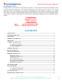
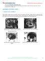
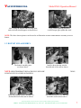
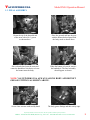
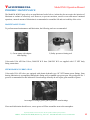
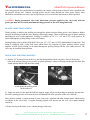
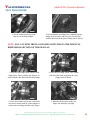
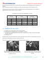
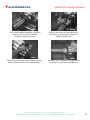
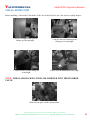
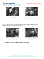
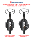
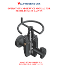
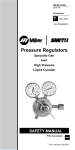
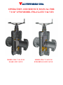
VALVEWORKS USA OPERATION AND SERVICE MANUAL FOR 7 1/16” 2/5M MODEL FM-4 GATE VALVES MODEL FM-4 7 1/16 2/5 M SLAB GATE VALVE MODEL FM-4 7 1/16 2/5 M EXPANDING GATE VALVE VALVEWORKS USA Model FM-4 Operation Manual INTRODUCTION In appreciation to our customer for purchasing our product, we have prepared this Operation Manual to assist you in the Operation, Maintenance, Assembly and Installation of the Valveworks USA API 6A 7-1/16 Model FM-4 gate valves. We encourage you to follow recommendations in this booklet to attain the best possible service from our product, which is designed and proven to offer the service one can expect of a quality product. If you need to contact a representative for more specific information pertaining to a special problem, please contact: EMAIL: WEBSITE: VALVEWORKS USA 1650 SWAN LAKE RD. BOSSIER CITY, LA 71111 PHONE: 318-425-0266 FAX# 318-425-0934 TOLL FREE: 888-425-0266 [email protected] WWW.VALVEWORKSUSA.COM CONTENTS APPLICATIONS ......................................................................................................................................................... 3 TEMPERATURE RATING ....................................................................................................................................... 3 TRIM CHART ............................................................................................................................................................. 3 ORDERING INFORMATION .................................................................................................................................. 4 OPERATION ............................................................................................................................................................... 4 ASSEMBLY INSTRUCTIONS .................................................................................................................................. 5 1.1. BODY SUB-ASSEMBLY ............................................................................................................................... 5 1.2. BONNET SUB-ASSEMBLY ........................................................................................................................... 7 1.3. FINAL ASSEMBLY....................................................................................................................................... 9 ASSEMBLY DRAWING .......................................................................................................................................... 12 BILL OF MATERIALS ............................................................................................................................................ 13 PHYSICAL DIMENSIONS ...................................................................................................................................... 14 PERIODIC MAINTENANCE.................................................................................................................................. 15 MAINTENANCE TOOLS ..................................................................................................................................... 15 STEM BEARING LUBRICATION ........................................................................................................................ 15 BODY LUBRICATION ........................................................................................................................................ 16 PLASTIC INJECTION PACKING ......................................................................................................................... 17 INSTALLING INJECTION PACKING ................................................................................................................... 17 PROCEDURE TO VENT OR DRAIN ...................................................................................................................... 17 MAINTAINANCE INTERVALS ............................................................................................................................. 17 TROUBLESHOOTING ............................................................................................................................................ 19 TEST PROCEDURE................................................................................................................................................. 15 2.1. HYDROSTATIC BODY TEST ...................................................................................................................... 21 2.2. HYDROSTATIC SEAT TEST....................................................................................................................... 22 VISUAL INSPECTION ............................................................................................................................................ 24 FIELD HOOK UP INSTRUCTIONS ...................................................................................................................... 25 Proprietary Booklet of Valveworks USA. Do not reproduce without explicit permission. Address: 1650 Swan Lake Road, Bossier City, LA-71111. Ph # 888-425-0266. Fax # 318-425-0934 2 VALVEWORKS USA Model FM-4 Operation Manual APPLICATIONS Valveworks USA Model FM-4 gate valves can be applied to the following sizes and working pressures. APPLICATION OPTIONS AVAILABLE Gate valve size Valve working pressure Temperature range 7-1/16” 2000-5000 psi -60°C to 121°C (-75°F to 250 °F) The Model FM-4 gate valves covered in this manual are suitable for performance requirement levels 1 and 2, PR1 and PR2 respectively. TEMPERATURE RATING Temperature classification Operating Range °C Min. -60 -46 -46 -29 -18 -18 -18 2 K L N P S T U V Max. 82 82 60 82 60 82 121 121 Min. -75 -50 -50 -20 0 0 0 35 (°F) Max. 180 180 140 180 140 180 250 250 TRIM CHART Minimum Material Requirements Material class AA - General service BB - General service CC - General service DD - Sour service a EE - Sour service a FF - Sour service a HH - Sour service a Body, bonnet, end and outlet connections Carbon or low-alloy steel Carbon or low-alloy steel Stainless steel Carbon or low-alloy steel b Carbon or low-alloy steel b Stainless steel b CRAs b a As defined by NACE MR 0175. b In compliance with NACE MR 0175. Pressure-controlling parts, stems and mandrel hangers Carbon or low-alloy steel Stainless steel Stainless steel Carbon or low-alloy steel b Stainless steel b Stainless steel b CRAs b Proprietary Booklet of Valveworks USA. Do not reproduce without explicit permission. Address: 1650 Swan Lake Road, Bossier City, LA-71111. Ph # 888-425-0266. Fax # 318-425-0934 3 VALVEWORKS USA Model FM-4 Operation Manual ORDERING INFORMATION The following information should be provided with any request for quote or order placement of Valveworks USA Model FM-4 gate valves: Model of Valve Size of Valve Pressure Rating (maximum) API 6A Requirements (PR-PSL) API 14D Requirements (Class of Service) Temperature Rating (API 6A) Material (API 6A) Any Special Test Requirements Any Special Material Requirements Any Special Coating or Protection Requirements Other Specifications and/or Certifications The model FM4 is a full bore 7-1/16 API 6A gate valve. Using a standard hand-wheel operation, the result is a high torque operation. The operating torque can be seriously reduced to half by using a Ball screw operator which is readily available as an upgrade for the Model FM4. OPERATION Valveworks USA Model FM-4 Expanding Gate and FM-4 Slab Gate valves are generally hand wheel operated. The expanding gate of the MODEL FM-4 Valve consists of two pieces (major and minor) acting one against the other by means of a dual wedge expanding when the valve is either fully closed or fully opened. The expansion effect of the wedge against the seats, through the parallel faces of the gate, provides a strong and positive seal against pulsations and vibrations created by flow conditions. The MODEL FM-4 slab gate valve is a one piece slab gate that uses two floating seats to generate a highly reliable seal. The slab gate eliminates the chance of trapping pressure within the body cavity which can cause pressure locking. 1. Fully open the valve before installing or shipping. The sealing area of the gates, in the full open position, is protected by the body and is less likely to be damaged. 2. Do not remove the molybdenum disulfide coating from internal parts. This coating serves as a lubricant and corrosion inhibitor. 3. To hydrostatically test the valve body to full API test pressure, the valve must be in a partially open position. When testing the valve in the closed position (seat test), do not exceed the working pressure stamped on the valve identification plate. 4. During storage always leave the valve in fully opened or fully closed position. This will tightly wedge the gate and segment against the seats and prevent damage to the sealing area of both the gate and seats. 5. When lubricating the body do not exceed the maximum API working pressure stamped on the identification plate. 6. The valve should be fully closed or fully opened during lubrication of the body or seats. 7. Seat lubrication pressures should not exceed the maximum allowable API test pressure. The expanding gate design of our Model M valves provides a tight mechanical positive seal; however to properly effect this seal, the valve must be fully opened or fully closed in order to wedge the gate and segment against Proprietary Booklet of Valveworks USA. Do not reproduce without explicit permission. Address: 1650 Swan Lake Road, Bossier City, LA-71111. Ph # 888-425-0266. Fax # 318-425-0934 4 VALVEWORKS USA Model FM-4 Operation Manual the seats. Do not back off the hand wheel. 8. This method of operation will prevent damage to the sealing surfaces of the gate and seats, and will increase the life of the valve. ASSEMBLY INSTRUCTIONS 1.1. BODY SUB-ASSEMBLY The procedure begins with the assembly of the lower bonnet to the body. Apply anti-seize compound to the body threads and screw the studs into them. Using a certified torque gun, tighten the studs and nuts on the body side. Insert a lower bonnet seal ring and then the bonnet and tighten the nuts on the bonnet side. Body, seat, gate and gate guides are shown in the figure above. The above figure is used for illustration purpose only. Insert the greased side into the body cavity as shown. Grease the back side of the seat as shown. Grease and insert the second seat as shown. Proprietary Booklet of Valveworks USA. Do not reproduce without explicit permission. Address: 1650 Swan Lake Road, Bossier City, LA-71111. Ph # 888-425-0266. Fax # 318-425-0934 5 VALVEWORKS USA Insert a gate guide as shown. Insert the gate assembly into the valve between the seats and in the gate guides. Model FM-4 Operation Manual The two inserted gate guides appear as shown. The gate segment should point in the same direction of the flow as shown above. (For expanding gate type only) NOTE: Model MSG slab gates are bidirectional and can be inserted with either side facing the flow. The gate should be between the seats and inside the gate guides as shown above. Coat all of the body threads with antiseize compound as shown above. Place the bonnet seal ring in the bonnet seal ring groove as shown above. Screw one stud into each of the holes as shown above. Proprietary Booklet of Valveworks USA. Do not reproduce without explicit permission. Address: 1650 Swan Lake Road, Bossier City, LA-71111. Ph # 888-425-0266. Fax # 318-425-0934 6 VALVEWORKS USA After coating the threads and screwing in the studs, the body should appear as shown above. Model FM-4 Operation Manual Using a stud tightening nut and a certified torque gun, tighten the studs NOTE: The above shown pictures can be used as an illustration to better understand the assembly of lower bonnet. 1.2. BONNET SUB-ASSEMBLY The bonnet assembly parts are shown above. Install a thrust bearing onto the threaded end of the stem as shown. NOTE: HIGH TEMPERATURE PACKING IS USED FOR THE EXAMPLE, BUT REGULAR PACKING IS INSTALLED IN A SIMILAR FASHION. Install the packing retainer bushing over the threaded end of the stem as shown. Place the packing over the threaded end of the stem as shown above. Proprietary Booklet of Valveworks USA. Do not reproduce without explicit permission. Address: 1650 Swan Lake Road, Bossier City, LA-71111. Ph # 888-425-0266. Fax # 318-425-0934 7 VALVEWORKS USA Wrap the stick packing around the threads above the stem packing and insert the threaded end into the bonnet. Insert the Bearing Retainer Nut and tighten with an expanding wrench. Insert the Bearing Retainer Locknut and tighten it with an expanding wrench as well. Model FM-4 Operation Manual Add second thrust bearing around stem and insert the bearing spacer sleeve as shown into the top of the bonnet. The bearing retainer nut should appear as shown above. Insert the alemite grease fitting. The finished bonnet assembly should appear similar to the one shown above. Proprietary Booklet of Valveworks USA. Do not reproduce without explicit permission. Address: 1650 Swan Lake Road, Bossier City, LA-71111. Ph # 888-425-0266. Fax # 318-425-0934 8 VALVEWORKS USA Model FM-4 Operation Manual 1.3. FINAL ASSEMBLY Grease the tip of the threaded end of the stem with a No. 3 grease as shown above. Place a hand wheel onto the stem and rotate the handwheel clockwise to lower the bonnet onto the body. Place the greased end into the gate with the bonnet holes aligned with the body studs as shown above. When the bonnet is lowered, remove the handwheel. The final assembly should appear as shown. NOTE: VALVEWORKS USA ALWAYS ALIGNS BODY AND BONNET GREASE FITTINGS AS SHOWN ABOVE. Screw a hex nut onto each stud by hand. The body grease fittings and their safety caps. Proprietary Booklet of Valveworks USA. Do not reproduce without explicit permission. Address: 1650 Swan Lake Road, Bossier City, LA-71111. Ph # 888-425-0266. Fax # 318-425-0934 9 VALVEWORKS USA The packing injection fitting for the bonnet. Model FM-4 Operation Manual Screw one of the body grease fittings into either of the grease fitting holes on the body. Screw the remaining grease fitting into the remaining hole on the body. Tighten one of the grease fittings with a certified torque Tighten the remaining grease fitting with a certified torque gun. Place the valve on the ground for stability. Tighten each of the body/bonnet hex nuts with a certified torque At this point, the assembly should appear similar to the one above. Proprietary Booklet of Valveworks USA. Do not reproduce without explicit permission. Address: 1650 Swan Lake Road, Bossier City, LA-71111. Ph # 888-425-0266. Fax # 318-425-0934 10 VALVEWORKS USA Screw a safety on one of the Body grease fittings. Screw the packing injection fitting into the bonnet. Place the handwheel onto the stem and secure it with a handwheel nut. The handle should point up as shown. Model FM-4 Operation Manual Then, screw the remaining safety cap onto the remaining body grease fitting. Tighten the packing injection fitting with a certified torque gun. The final assembly should appear similar to the one above. Proprietary Booklet of Valveworks USA. Do not reproduce without explicit permission. Address: 1650 Swan Lake Road, Bossier City, LA-71111. Ph # 888-425-0266. Fax # 318-425-0934 11 VALVEWORKS USA Model FM-4 Operation Manual ASSEMBLY DRAWING Proprietary Booklet of Valveworks USA. Do not reproduce without explicit permission. Address: 1650 Swan Lake Road, Bossier City, LA-71111. Ph # 888-425-0266. Fax # 318-425-0934 12 VALVEWORKS USA Model FM-4 Operation Manual BILL OF MATERIALS ITEM 1 2 3 4 5 6 7 8 9 9a 9b 10 11 12 13 14 15 16 16a 16b 17 18 19 20 21 22 23 24 25 PART NO. 235-57XY-DB 205-57XY 096-5700-A 070-57XY 109-0001 105-0001 101-0001 034-57XY 089-FM4-5700 082-0000 055-5700 206-57XY 096-5700-A 071-57XY 052-52XY 002-57XY 110-57XY 031-57XY-1 060-57XY 135-5700 135-5700 135-5700 155-57XY 032-3291 990-0007 041-57XY DESCRIPTION BODY BONNET, UPPER STUD & NUT, UPPER BONNET SEAL RING, UPPER GREASE FITTING, ALEMITE PACKING INJECTION FITTING BODY GREASE FITTING STEM PACKING SET, CHEVRON V PACKING INJECTION PACKING INJECTION, SLEEVE BONNET, LOWER STUD & NUT, LOWER BONNET SEAL RING, LOWER PACKING RETAINER BUSHING GATE, SLAB THRUST BEARING SEAT ASSEMBLY TEFLON INSERT O-RING, BACKSEAL GATE GUIDE HANDWHEEL HANDWHEEL NUT HANDWHEEL WASHER BEARING HOUSING WEATHER SEAL, O-RING NAME PLATE GREASE DRIVE NUT QUANTITY 1 1 16 1 1 1 2 1 1 1 1 1 16 1 1 1 2 2 2 2 2 1 1 1 1 1 1 FILL 1 The last two digits in the part no’s vary with X - “Material Type and Y – “Coating. The table below gives the different available material types and coatings. Please refer to the valve tag to see the material type and coating on the valve parts. Proprietary Booklet of Valveworks USA. Do not reproduce without explicit permission. Address: 1650 Swan Lake Road, Bossier City, LA-71111. Ph # 888-425-0266. Fax # 318-425-0934 13 VALVEWORKS USA Model FM-4 Operation Manual X MATERIAL TYPE Y COATING 1 1A 1B 1C 1D 1E 1F 2 2A 3 3A 4 4A 4B 5 6 6A 6B 7 8 8A 8B 8C 8D 8E 9 9A 9B 4130 4140 1040 1018 1020 SA285-C 1026 410SS FORGED S42400 174SS NITRONIC 50 316SS 316/304SS 304SS BRONZE INCONEL 718 INCONEL 725 INCONEL X750 MONEL A487-4D A487-4C CA15 CF8M CF3M CA6NM STELLITE #6 PLASTIC STELLITE #3 0 NONE; PHOSPHATE, MOLY, STANDARD PAINT/COATING, POWDER COAT NITRIDE QPQPHOSPHATE; EXCEPTION - FC BODY BUSHING DO NOT NITRIDE HARDFACESTELLITE #6 SPRAY & FUSE HARDFACE TUNGSTEN CARBIDE HARDFACE COLMONOY #5 ELECTROLIS NICKEL WELD ON HARDFACE ZINC PLATE XYLAN COATING (4130) INCONEL 625 CLAD (4130)SS-316-RING GROOVE 1 2 3 4 5 6 7 8 9 9A PHYSICAL DIMENSIONS Dimensions A B C D E F 2000 psi 26 1/8 7 1/16 16 5/8 34 ½ 24 15 ½ 3000 psi 28 1/18 7 1/16 16 5/8 34 ½ 24 15 ½ 5000 psi 32 7 1/16 16 5/8 34 ½ 30 15 ½ All dimensions are in inches. Proprietary Booklet of Valveworks USA. Do not reproduce without explicit permission. Address: 1650 Swan Lake Road, Bossier City, LA-71111. Ph # 888-425-0266. Fax # 318-425-0934 14 VALVEWORKS USA Model FM-4 Operation Manual PERIODIC MAINTENANCE The Model M & MSG gate valves are non-lubricated sealed valves, in that they do not require the injection of lubricants or sealants to effectively seal. However, to prevent corrosion, excessive wear and ensure continued operation, a normal amount of lubrication is recommended to extend the life and serviceability of the valve. MAINTENANCE TOOLS To perform normal maintenance and lubrication, the following tools are recommended: 1) Grease pump with adapter and coupling. 2) Safety pressure releasing tool. Valveworks USA API Gate Valves, 2000 PSI W.P. thru 5,000 PSI W.P. are supplied with 1/2" NPT body fitting connections. STEM BEARING LUBRICATION Valveworks USA API valves are equipped with alemite hydraulic type 1/8" NPT bonnet grease fittings. Stem bearing lubrication is accomplished through this fitting using a standard type grease gun. Any good grade No. 3 grease is recommended for this lubrication. Stem bearings normally do not require great amounts of grease. An example of using a grease gun to grease the stem bearings If too much lubrication should occur, excess grease will flow around the stem to the atmosphere. Proprietary Booklet of Valveworks USA. Do not reproduce without explicit permission. Address: 1650 Swan Lake Road, Bossier City, LA-71111. Ph # 888-425-0266. Fax # 318-425-0934 15 VALVEWORKS USA Model FM-4 Operation Manual CAUTION: IF BEARINGS NEED TO BE CHANGED, THE VALVE MUST BE REMOVED FROM SERVICE. BODY LUBRICATION Valves may require body lubrication if they become hard to operate or when they are used in corrosive service conditions. For this purpose, each valve has two safety ball check fittings located at the bottom and top of the body of the valve. Valveworks USA recommends its OEM grease as standard, however; any good grade 3, 4 or 5 grease is recommended for body lubrication, but caution is to be taken so as not to use soluble grease near the product flowing through the valve. Approximately one pound of grease per inch of nominal valve bore size is sufficient to provide adequate lubrication. Place the valve in the fully opened or fully closed position before lubricating the valve. 1. Remove the safety caps from both safety ball check fittings. 2. Install the grease gun fitting (with gauge) on either of the grease fittings. 3. Install the pressure release tool on the other grease fitting. A 1/2" NPT 10,000 psi W.P. needle valve may be attached to the outlet of the pressure release tool as a safety measure, should the ball check not hold pressure. Open 1/2" needle valve, rotate handle of pressure release tool clockwise until main stem makes contact with the ball check; unseat same to release existing body pressure. Proprietary Booklet of Valveworks USA. Do not reproduce without explicit permission. Address: 1650 Swan Lake Road, Bossier City, LA-71111. Ph # 888-425-0266. Fax # 318-425-0934 16 VALVEWORKS USA Model FM-4 Operation Manual If the body pressure does not bleed down completely, the volume of the pressure released can be controlled with the pressure release tool. Continue injecting grease into the body through the other grease fitting. After lubrication, reinstall the two safety caps and operate the valve several times and return to desired position. CAUTION: During pressurized valve body lubrication, pressure applied to the valve body with the grease gun must not exceed the maximum working pressure of the valve being lubricated. PLASTIC INJECTION PACKING Plastic packing is added to the stuffing box through the plastic injection fitting on the valve bonnet to further energize the packing around the stem, shutting off package leakage. There are different types of plastic packing depending on service and temperature. Packing is available in 3/8" X 1" (9.5 mm X 25.4 mm) sticks to be injected through the packing fitting on the valve bonnet. Packing fittings used on Model M & MSG valves are 1/2" (12.7 mm) 14 NPT standard thread connection. This fitting is equipped with a safety ball check which allows the insertion of plastic packing without special adapters or tools. Stick packing can be added through the packing fitting with the valve under pressure. The valve may be installed in any position. INSTALLING INJECTION PACKING 1) Run the 3/4" hex head screw all the way into the fitting and then back out slowly; observe the bleeder hold in the packing fitting. If no pressure or plastic packing is observed flowing out through this hole, this would indicate that the ball check has seated. At this point, the packing screw can be removed. 2) Apply one stick at a time until the leak has stopped. Apply only as much packing as needed to stop the leak. Excessive packing pressure will cause the stem to bind and will make operation of the valve difficult. Most products contain a certain amount of water, lime scale, sediment and other foreign matter which tend to accumulate in the valve body. A regular draining program will increase the life of a valve against damage caused by: 1) Water freezing in the body cavity, causing damage to the body. Proprietary Booklet of Valveworks USA. Do not reproduce without explicit permission. Address: 1650 Swan Lake Road, Bossier City, LA-71111. Ph # 888-425-0266. Fax # 318-425-0934 17 VALVEWORKS USA Model FM-4 Operation Manual 2) An accumulation of foreign matter in the lower part of the body, which could prevent the valve from fully closing, resulting in a throttling action which may cause inefficient sealing. 3) Foreign matter trapped in the body may become lodged between the sealing surfaces of the gate and seats, resulting in scored or damaged sealed. 4) Venting a Model M & MSG valve, is a positive method of checking the sealing ability of the gate and seats. If the body vents down to zero pressure with the valve in fully closed position, this is definite indication that sealing surfaces are in good condition. PROCEDURE TO VENT OR DRAIN 1. Place the valve gate in a fully opened or fully closed position. 2. Remove the safety cap from either body grease fitting and attach the pressure release tool. CAUTION: Remove the safety cap slowly to allow the ball check to sufficiently seal, to avoid uncontrolled venting. Should the ball check fail to seal properly, pressure will continue to blow through the safety cap orifices. You should then retighten the safety cap screw and vent through the other body grease fitting. Once the body pressure is bled to zero you should then attempt to repair the leaking ball check. 3. Screw the stem of the releasing tool into the fitting forcing the ball check off its seat. The valve will vent and drain once the ball check is unseated. A program of regular draining and body venting is the most positive way to prevent problems caused by foreign matter in the valve. However, if a regular draining program cannot be followed, it is recommended that valves be drained after the following operations: 1) After a well has come in and has been cleaned up. 2) After a mudding operation. 3) After a cementing operation. 4) Anytime the valve seems hard to operate by hand and will not fully open or close by the required number of handwheel turns. 5) When the valve is hard to operate from the fully open or fully closed position because it is "pressure locked" or "Iced-up". "Pressure locked" is a condition that may exist with any dual seat expanding type gate valve when body pressure greatly exceeds line pressure. It occurs only in fully closed position and is a positive indication that sealing surfaces are in good condition. "Iced-up" is a condition caused by a restriction in the flow or a differential in the pressure of gas flow at high pressure, which produces extremely low temperatures. These restrictions or differentials in pressure may be caused by throttling through a valve, by leakage of a closed valve or by Leakage through the stem packing. Valves in service on gas containing hydrates or in fresh water service, exposed to low external temperatures may also "iced-up". In this case it is advisable to inject alcohol or glycol into the valve body through the drain fitting to combat these conditions. The same procedures are used for injecting alcohol or glycol as are used for valve body lubrication. Do not operate the valve immediately after injecting as these fluids should be retained in the body to perform the Antifreeze effect. Proprietary Booklet of Valveworks USA. Do not reproduce without explicit permission. Address: 1650 Swan Lake Road, Bossier City, LA-71111. Ph # 888-425-0266. Fax # 318-425-0934 18 VALVEWORKS USA Model FM-4 Operation Manual IDENTIFICATION PLATE Identification plates are attached to all Valveworks USA API Production Gate Valves. They are located on the bonnet of each valve and warrants that all products are manufactured to design and quality control specifications of industry standards. The information listed on the identification plate should be referred to when ordering replacement parts. MAINTENANCE INTERVALS Procedure Recommended Interval Vent or Drain See Page 8 Cycle Open to Close Semi-Annually Disconnect & Test Annually These are just recommended intervals of maintenance. Depending on the level of usage, your valve(s) may require more or less maintenance than this manual suggests. For more information, contact Valveworks USA. TROUBLESHOOTING Problem Cause Leakage when closed Seats Leakage when open thru body/bonnet connection Leakage when partially open thru top of bonnet Bonnet Seal Ring Leakage at flange Packing Flange Seal Ring Solution Disconnect from service and replace the seats. Disconnect from service and replace the bonnet seal ring. Disconnect from service and replace the packing. Disconnect from service and replace the flange seal ring. For extra assistance with these or any other problems, please contact Valveworks USA Proprietary Booklet of Valveworks USA. Do not reproduce without explicit permission. Address: 1650 Swan Lake Road, Bossier City, LA-71111. Ph # 888-425-0266. Fax # 318-425-0934 19 VALVEWORKS USA Model FM-4 Operation Manual TEST PROCEDURE 1. Grease and insert the ring joint into one of the body flanges. 2. Be sure that the test flange has a tightened grease fitting, all of its studs, and a hex nut on each stud with the hex nuts on the grease fitting side as shown. NOTE: YOU CAN FIND THE FLANGE RING JOINT SIZE IN THE PHYSICAL DIMENSIONS SECTION OF THIS MANUAL. 3. Align the test flange studs with the body flange holes. Then, push the test flanges, its studs, and their hex nuts onto the body flange. 4. Place the test flange on the valve flange with all of the studs going thru the valve flange holes as shown. 5. Screw the each hex nut on the vacant side of a stud as shown until all of the studs have a nut on the test flange and the valve flange. 6. Hammer the hex nuts on the test flange side until they are tight. Proprietary Booklet of Valveworks USA. Do not reproduce without explicit permission. Address: 1650 Swan Lake Road, Bossier City, LA-71111. Ph # 888-425-0266. Fax # 318-425-0934 20 VALVEWORKS USA Model FM-4 Operation Manual 7. A finished flange should appear as shown. REPEAT STEPS 1-7 FOR THE OPPOSITE FLANGE. . Remove the safety cap from one of the test flange grease fittings and attach a pressure release tool as shown above. Remove the grease fitting cap from the opposite test flange and attach the flow line as shown above. 2.1. HYDROSTATIC BODY TEST With the pressure release tool and flow line connection tight, open the valve partially, and apply the test pressure for at least three (3) minutes. Bleed off the pressure until it’s reduced to zero, and close the pressure release tool. Proprietary Booklet of Valveworks USA. Do not reproduce without explicit permission. Address: 1650 Swan Lake Road, Bossier City, LA-71111. Ph # 888-425-0266. Fax # 318-425-0934 21 VALVEWORKS USA Model FM-4 Operation Manual Raise the pressure back up to the test pressure for the secondary pressure-holding period of at least three (3) minutes. Bleed off the pressure until it’s reduced to zero. Then, close the pressure release tool and the valve. The hydrostatic body test pressure shall be determined by the rated working pressure of the equipment. Hydrostatic test pressures shall be as given in Table 1. HYDROSTATIC BODY TEST PRESSURE, PSI (MPa) Working Pressure Rating - PSI (Mpa) 2,000 (13,8) 3,000 (20,7) 5,000 (34,5) 10,000 (69,0) 15,000 (103,4) 20,000 (138,0) End and Outlet Connections - PSI (Mpa) 4,000 (27,6) 6,000 (41,4) 7,500 (51,7) 15,000 (103,4) 22,500 (155,2) 30,000` (207,0) Line Pipe and Tubing Threads - PSI (Mpa) 4,000 (27,6) 6,000 (41,4) 7,500 (51,7) 15,000 (103,4) - 2.2. HYDROSTATIC SEAT TEST A. With the valve closed, apply the rated working pressure. B. Hold and monitor at that pressure for at least three (3) minutes. C. Open the valve, and bleed off the pressure until it’s reduced to zero. Then, close the valve and the pressure release tool. D. Repeat steps A-C. Switch the sides of your flow and pressure release connections, bleed off the new pressure release side, and repeat steps A-D to perform a seat test on the new flow side. The valve is acceptable if no leakage is visible during the holding period. While holding the hex nuts on the body flange, loosen each of the test flange hex nuts with a certified torque gun. After removing the body flange hex nuts, you can remove the test flange, its studs, and their hex nuts. Proprietary Booklet of Valveworks USA. Do not reproduce without explicit permission. Address: 1650 Swan Lake Road, Bossier City, LA-71111. Ph # 888-425-0266. Fax # 318-425-0934 22 VALVEWORKS USA Pass a drift mandrel through the valve bore after the valve has been assembled, operated, and pressure tested. Remove the lower bonnet grease fitting cap, and attach a pressure release tool as shown above. Model FM-4 Operation Manual Remove one of the cap, and attach a flow line from the grease pump to the grease fitting as shown above. After the valve is accepted, it is tagged with a green or blue tag before being painted. Proprietary Booklet of Valveworks USA. Do not reproduce without explicit permission. Address: 1650 Swan Lake Road, Bossier City, LA-71111. Ph # 888-425-0266. Fax # 318-425-0934 23 VALVEWORKS USA Model FM-4 Operation Manual VISUAL INSPECTION Before installing a Valveworks USA Model 1540 valve in the field, here are a few items to visually inspect: 1. Be sure the upper bonnet grease fitting cap is on and tight. 3. Make sure the Alemite fittings are on and tight 2. Be sure the lower bonnet grease fitting cap is on and tight. 4. Make sure the Handwheel Nut is tight NOTE: THE GLAND BACKSEAT WILL BE SCREWED INTO THE FINISHED VALVE. Make sure the gate is in the open position Proprietary Booklet of Valveworks USA. Do not reproduce without explicit permission. Address: 1650 Swan Lake Road, Bossier City, LA-71111. Ph # 888-425-0266. Fax # 318-425-0934 24 VALVEWORKS USA Model FM-4 Operation Manual FIELD HOOK UP INSTRUCTIONS Grease and insert the ring joint into one of the body flanges. Align the service flange holes with the body flange holes. Push a stud thru each aligned hole until there is a stud thru each hole. Screw a hex nut on both sides of each stud by hand. NOTE: YOU CAN FIND THE FLANGE RING JOINT SIZE IN THE PHYSICAL DIMENSIONS SECTION OF THIS BOOKLET. Tighten the service flange hex nuts with an certified torque gun. A finished flange should appear as shown. REPEAT STEPS 1-4 FOR THE OPPOSITE FLANGE. Proprietary Booklet of Valveworks USA. Do not reproduce without explicit permission. Address: 1650 Swan Lake Road, Bossier City, LA-71111. Ph # 888-425-0266. Fax # 318-425-0934 25