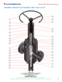
1
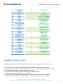
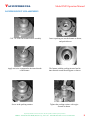
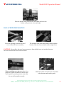
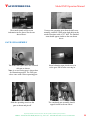
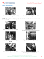
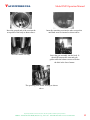
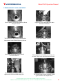
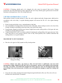
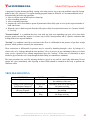
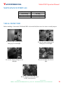
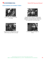
VALVEWORKS USA OPERATION AND SERVICE MANUAL FOR MODEL FM 2 4-1/16 GATE VALVE VALVEWORKS USA Model FM2 Operation Manual INTRODUCTION In appreciation to our customer for purchasing our product, we have prepared this Operation Manual to assist you in the Operation, Maintenance, Assembly and Installation of the Valveworks USA API 6A 4-1/16 inch FM2 Gate Valve. We encourage you to follow recommendations in this booklet to attain the best possible service from our product, which is designed and proven to offer the service one can expect of a quality product. If you need to contact a representative for more specific information pertaining to a special problem, you should contact: EMAIL: WEBSITE: VALVEWORKS USA 1650 SWAN LAKE RD. BOSSIER CITY, LA 71111 PHONE: 318-425-0266 FAX# 318-425-0934 TOLL FREE: 888-425-0266 [email protected] WWW.VALVEWORKSUSA.COM CONTENTS APPLICATIONS .............................................................................................................. 3 TEMPARATURE RATING ............................................................................................ 3 TRIM CHART .................................................................................................................. 3 ORDERING INFORMATION ........................................................................................ 4 OPERATION ................................................................................................................... 4 ASSEMBLY DRAWING ................................................................................................. 5 BILL OF MATERIALS ................................................................................................... 6 ASSEMBLY INSTRUCTIONS .................................................................................................. 7 LOWER BONNET SUB ASSEMBLY ......................................................................................... 8 BALL SCREW PREPARATION ............................................................................................... 9 GATE SUB ASSEMBLY ........................................................................................................ 10 BODY SUB ASSEMBLY ........................................................................................................ 11 UPPER BONNET SUB ASSEMBLY ......................................................................................... 13 BALL SCREW ASSEMBLY ................................................................................................... 14 FINAL ASSEMBLY .............................................................................................................. 17 PERIODIC MAINTENANCE ....................................................................................... 21 BALL SCREW LUBRICATION .............................................................................................. 21 VENTING/DRAINING A VALVE ........................................................................................... 22 TROUBLESHOOTING ................................................................................................. 23 MAINTAINANCE INTERVALS .................................................................................. 24 VISUAL INSPECTION.................................................................................................. 24 FIELD HOOKUP INSTRUCTIONS ............................................................................ 25 Proprietary Booklet of Valveworks USA. Do not reproduce without explicit permission. Address: 1650 Swan Lake Road, Bossier City, LA-71111. Ph # 888-425-0266. Fax # 318-425-0934 2 VALVEWORKS USA Model FM2 Operation Manual APPLICATIONS Valveworks USA 4-/16” FM2 gate valve unit can be applied to the following sizes and working pressures. APPLICATION OPTIONS AVAILABLE Gate valve size Valve working pressure Temperature range 4-1/16” 15,000 psi -60°C to 121°C (-75°F to 250 °F) The FM2 gate valves covered in this manual are suitable for performance requirement levels (PSL) 1 and 2, PR1 and PR2 respectively. TEMPERATURE RATING Temperature classification K L N P S T U V Operating Range Min. °C Max. Min. (°F) Max. -60 -46 -46 -29 -18 -18 -18 2 82 82 60 82 60 82 121 121 -75 -50 -50 -20 0 0 0 35 180 180 140 180 140 180 250 250 TRIM CHART Material class AA - General service BB - General service CC - General service DD - Sour service a EE - Sour service a FF - Sour service a HH - Sour service a Minimum Material Requirements Pressure-controlling Body, bonnet, end and parts, stems and mandrel outlet connections hangers Carbon or low-alloy steel Carbon or low-alloy steel Stainless steel Carbon or low-alloy steel b Carbon or low-alloy steel b Stainless steel b CRAs b a As defined by NACE MR 0175. b In compliance with NACE MR 0175. Carbon or low-alloy steel Stainless steel Stainless steel Carbon or low-alloy steel b Stainless steel b Stainless steel b CRAs b As shown by API-6A. For specific details, consult Valveworks USA. Proprietary Booklet of Valveworks USA. Do not reproduce without explicit permission. Address: 1650 Swan Lake Road, Bossier City, LA-71111. Ph # 888-425-0266. Fax # 318-425-0934 3 VALVEWORKS USA Model FM2 Operation Manual ORDERING INFORMATION The following information should be provided with any request for quote or order placement of Valveworks USA 4-1/16” FM2 Gate Valves: API 6A Requirements (PR-PSL) Temperature Rating (API 6A) Material (API 6A) Any Special Test Requirements Any Special Material Requirements Any Special Coating or Protection Requirements Other Specifications and/or Certifications OPERATION The Valveworks USA Model FM2 gate valves are Ball Screw operated valves. The gate of the MODEL FM2 Valve is a one piece slab gate that uses two floating seats to generate a highly reliable seal. The slab gate eliminates the chance of trapping pressure within the body cavity which can cause pressure locking. Fully open the valve before installing or shipping. The sealing area of the gates, in the full open position, is protected by the body and is less likely to be damaged. Do not remove the molybdenum disulfide coating from internal parts. This coating serves as a lubricant and corrosion inhibitor. To hydrostatically test the valve body to full API test pressure, the valve must be in a partially open position. When testing the valve in the closed position (seat test) do not exceed the working pressure stamped on the valve identification plate. During storage always leave the valve in the fully opened or fully closed position. This will tightly wedge the gate against the seats and prevent damage to the sealing area of both the gate and seats. Always remove the valve from service before work is performed on the stem bearings. When lubricating the body do not exceed the maximum API working pressure stamped on the identification plate. The valve should be fully closed or fully opened during lubrication of the body or seats. Seat lubrication pressures should not exceed the maximum allowable API test pressure. This method of operation will prevent damage to the sealing surfaces of the gate and seats, and will increase the life of the valve. Proprietary Booklet of Valveworks USA. Do not reproduce without explicit permission. Address: 1650 Swan Lake Road, Bossier City, LA-71111. Ph # 888-425-0266. Fax # 318-425-0934 4 VALVEWORKS USA Model FM2 Operation Manual ASSEMBLY DRAWING OF MODEL FM2 GATE VALVE Proprietary Booklet of Valveworks USA. Do not reproduce without explicit permission. Address: 1650 Swan Lake Road, Bossier City, LA-71111. Ph # 888-425-0266. Fax # 318-425-0934 5 VALVEWORKS USA Model FM2 Operation Manual BILL OF MATERIALS ITEM PART NO DESCRIPTION QTY 1 2 3 4 5 6 7 8 9 10 11 12 13 14 15 16 17 18 19 20 21 22 23 24 25 26 27 28 29 30 31 32 33 34 35 290-FM2-84XY 291-FM2-84XY 292-FM2-3-84XY 380-FM2-8400 096-8400-A 096-8400-C 319-FM2-8440 BX-152 109-0001 108-0003 640-FM2-84XY 341-FM3-85XY 351-8500 606-FM2-8411 344-FM2-8411 601-FM2-84XY 602-FM2-8423 334-FM2-8400 609-FM2-84XY 155-FM1-77XY 397-7700 377-FM1-77XY 374-FM1-77XY 345-FM1-77XY 346-FM1-77XY 387-FM1-77XY 381-FM1-7710 373-FM1-7700 369-7700 348-7700 349-7700 032-3502 032-3272 990-0007 400-0002 BODY BONNET BONNET, LOWER HANDWHEEL STUDS / NUTS STUDS / NUTS BONNET SEAL RING RING GASKET GREASE FITTING, ALEMITE GREASE FITTING, BODY OPERATING STEM BALANCING STEM PACKING, STEM UPPER PACKING RETAINER LOWER PACKING GLAND NUT GATE SEAT SEAT SEAL STEM PROTECTOR BEARING HOUSING BALLSCREW, LH THREAD BEARING SPACER, LOWER BEARING SPACER, UPPER COVER PLATE STEM, ADAPTER GLAND, BACKSEAT HANDWHEEL NUT BEARING BEARING, UPPER SNAP RING ROD WIPER - D-3250 O-RING - #350 O-RING - #327 VALVE TAG GREASE 1 1 1 1 12 8 1 1 3 2 1 1 2 1 1 1 2 2 1 1 1 1 1 1 1 1 1 2 1 1 1 3 1 1 4.25 LBS The last two digits in the part no’s vary with X - “Material Type and Y – “Coating. The table below gives the different available material types and coatings. Please refer to the valve tag to see the material type and coating on the valve parts. Proprietary Booklet of Valveworks USA. Do not reproduce without explicit permission. Address: 1650 Swan Lake Road, Bossier City, LA-71111. Ph # 888-425-0266. Fax # 318-425-0934 6 VALVEWORKS USA Model FM2 Operation Manual X MATERIAL TYPE Y COATING 1 1A 1B 1C 1D 1E 1F 2 2A 3 3A 4 4A 4B 5 6 6A 6B 7 8 8A 8B 8C 8D 8E 9 9A 9B 4130 4140 1040 1018 1020 SA285-C 1026 410SS FORGED S42400 174SS NITRONIC 50 316SS 316/304SS 304SS BRONZE INCONEL 718 INCONEL 725 INCONEL X750 MONEL A487-4D A487-4C CA15 CF8M CF3M CA6NM STELLITE #6 PLASTIC STELLITE #3 0 NONE; PHOSPHATE, MOLY, STANDARD PAINT/COATING, POWDER COAT NITRIDE QPQPHOSPHATE; EXCEPTION - FC BODY BUSHING DO NOT NITRIDE HARDFACESTELLITE #6 SPRAY & FUSE HARDFACE TUNGSTEN CARBIDE HARDFACE COLMONOY #5 ELECTROLIS NICKEL WELD ON HARDFACE ZINC PLATE XYLAN COATING (4130) INCONEL 625 CLAD (4130)SS-316-RING GROOVE 1 2 3 4 5 6 7 8 9 9A ASSEMBLY INSTRUCTIONS The following steps have to be followed before assembly of any component of the FM2 gate valves. Assembly work area must be clean and free of dirt, metallic shavings and wood particles. Surface preparation of work area should be metallic or covered with a layer of corrugated cardboard. All lubricants and utensils used in assembly must be clean. All tools used in assembly must be clean and in good working order. Clean all components (metallic) prior to assembly. Keep all elastomers and plastic base materials in bags or boxes until needed for assembly. Inspect all components for burrs, dings, marks, scrapes, nicks, and etc. prior to assembly. Proprietary Booklet of Valveworks USA. Do not reproduce without explicit permission. Address: 1650 Swan Lake Road, Bossier City, LA-71111. Ph # 888-425-0266. Fax # 318-425-0934 7 VALVEWORKS USA Model FM2 Operation Manual LOWER BONNET SUB-ASSEMBLY 5 1/8” 10/15M FM3 bonnet before assembly Apply anti-seize compound to the inner threads of the bonnet. Screw in the packing retainer. Insert a packing set into the bonnet as shown, and push it down. The bonnet with the packing inserted and its inner threads coated should appear as shown. Tighten the packing retainer with a pipe wrench as shown. Proprietary Booklet of Valveworks USA. Do not reproduce without explicit permission. Address: 1650 Swan Lake Road, Bossier City, LA-71111. Ph # 888-425-0266. Fax # 318-425-0934 8 VALVEWORKS USA Model FM2 Operation Manual Place the balance stem protector onto the bonnet and screw the balance stem protector down until tight. BALL SCREW PREPARATION Screw the operating stem into the travel screw of the ball screw assembly. The shoulder of the stem should make contact with the bottom of the travel screw similar to the sample above. CAUTION: Do not allow the travel screw to unscrew from the ball screw nut in either direction. This will cause the ball screw to de-ball itself. When assembling more than one valve, it is a good idea to label or number the travel screw and its specific operating stem to ensure that the two will assemble correctly. Mark the location of 2 socket set screw holes with a hammer and transfer punch. Proprietary Booklet of Valveworks USA. Do not reproduce without explicit permission. Address: 1650 Swan Lake Road, Bossier City, LA-71111. Ph # 888-425-0266. Fax # 318-425-0934 9 VALVEWORKS USA The transfer punch will leave an indentation in two places like the one shown above. Model FM2 Operation Manual Unscrew the operating stem from the ball screw assembly, and drill 2 drill point depth holes at the marked locations with a 0.25” drill. The finished stem should appear similar to the one shown above. GATE SUB ASSEMBLY The Model FM2 gate valve uses a slotted slab gate as shown. Note: A reverse acting gate is shown here for illustration purpose. The FM2 gate valves come with a direct operating gate. Slide the operating stem in to the gate as shown and pin off. Insert balancing stem which screws in to the gate. Pin off after screwing in. The completed gate assembly should appear similar to the one above. Proprietary Booklet of Valveworks USA. Do not reproduce without explicit permission. Address: 1650 Swan Lake Road, Bossier City, LA-71111. Ph # 888-425-0266. Fax # 318-425-0934 10 VALVEWORKS USA Model FM2 Operation Manual BODY SUB ASSEMBLY Insert the studs into the top of the valve body. Coat the threads of the body/bonnet stud holes. NOTE: The top of the valve body is generally referred to as the vacant side where you can read the stencil details on the body. Screw a stud into each empty, coated hole. All of the studs should be inserted as shown above. A stud-tightening nut will be used to tighten the studs. Tighten the studs with an impact wrench. Grease the back and backside edge of the seats Then, grease and insert the external seal rings into the seal ring groove of each of the seats. Proprietary Booklet of Valveworks USA. Do not reproduce without explicit permission. Address: 1650 Swan Lake Road, Bossier City, LA-71111. Ph # 888-425-0266. Fax # 318-425-0934 11 VALVEWORKS USA Model FM2 Operation Manual Insert the greased end of the seat into the seat pocket of the body as shown above. Insert the remaining seat into the other seat pocket until both seats are inserted as shown above. Insert the bonnet seat ring. Lower the gate assembly into the body. It should fit between the seats and gate guides while the balance stem travels thru the hole in the lower bonnet. The operating stem should stand up as shown above. Proprietary Booklet of Valveworks USA. Do not reproduce without explicit permission. Address: 1650 Swan Lake Road, Bossier City, LA-71111. Ph # 888-425-0266. Fax # 318-425-0934 12 VALVEWORKS USA Model FM2 Operation Manual UPPER BONNET SUB ASSEMBLY Insert a packing set into the bonnet as shown, and push it down. The bonnet with the packing inserted and its inner threads coated should appear as shown. Once tight, the packing retainer should be as shown above. After screwing a hex nut on each stud, tighten each with a certified torque gun. Apply anti-seize compound to the inner threads of the bonnet. Screw in the packing retainer. Place the bonnet on the body over the top set of studs. Then, screw a hex nut onto each stud. The finished upper bonnet assembly should appear similar to the sample above. Proprietary Booklet of Valveworks USA. Do not reproduce without explicit permission. Address: 1650 Swan Lake Road, Bossier City, LA-71111. Ph # 888-425-0266. Fax # 318-425-0934 13 VALVEWORKS USA Model FM2 Operation Manual BALL SCREW SUB ASSEMBLY Raise the gate up until the stem is back seated. Then, lay the valve down. The operating stem should protrude as shown above. The lower bearing spacer with the o-ring should appear as shown. Place the lower bearing spacer (snap ring end first) over the operating stem. Apply thread locking solution to the top threads of the operating stem. Place a 350 o-ring on the lower bearing spacer as shown above. Place the snap ring onto the other side of the lower bearing spacer. Afterwards, the lower bearing spacer should appear as shown above. Place the upper bearing spacer on the ball screw as shown above. Proprietary Booklet of Valveworks USA. Do not reproduce without explicit permission. Address: 1650 Swan Lake Road, Bossier City, LA-71111. Ph # 888-425-0266. Fax # 318-425-0934 14 VALVEWORKS USA The ball screw should rest in the recess area on the spacer as shown. Model FM2 Operation Manual Place a bearing-race set over the travel screw and onto the upper bearing spacer. Screw the travel screw onto the top threads of the operating stem as shown above. If it is not already, unscrew the ball screw, with the upper bearing spacer and bearing-race set, to reveal 2 holes for socket set screws as shown above. Adjust Lower Bearing Spacer where milled slot is in line with set screw. Screw in the ¼”20UNC socket set screws, and tighten them with a ¼” Allen wrench. Roll the ball screw nut, upper bearing spacer, and bearing-race set back onto the lower bearing spacer. Then, apply anti-seize compound to the threads of the ball screw nut as shown above. Screw the stem adapter onto the ball screw nut as shown above. Wipe any excess anti-seize compound from underneath the stem adapter. Then, cover the upper bearing spacer and bearing-race set as shown above. Proprietary Booklet of Valveworks USA. Do not reproduce without explicit permission. Address: 1650 Swan Lake Road, Bossier City, LA-71111. Ph # 888-425-0266. Fax # 318-425-0934 15 VALVEWORKS USA Model FM2 Operation Manual CAUTION: DO NOT ALLOW THE TRAVEL SCREW TO UNSCREW FROM THE BALL SCREW NUT IN EITHER DIRECTION. THIS CAN CAUSE THE BALL SCREW TO DE-BALL. Weld the stem adapter to the ball screw nut as shown above. The finish weld should appear similar to the one shown above. Place a bearing-race set onto the stem adapter as shown above. The ball screw assembly should appear very similar to the one above. Grease the lower bearing-race set that is between the upper and lower bearing spacers. Grease the upper bearing-race set that is resting on the stem adapter. The greased ball screw assembly should appear very similar to the one shown above. Proprietary Booklet of Valveworks USA. Do not reproduce without explicit permission. Address: 1650 Swan Lake Road, Bossier City, LA-71111. Ph # 888-425-0266. Fax # 318-425-0934 16 VALVEWORKS USA Model FM2 Operation Manual FINAL ASSEMBLY Unscrew the ball screw assembly until there is approximately a 4.25” space between the bottom of the lower bearing spacer and the top of the upper bonnet. Use a jack-bolt to secure the space. Coat the outer threads of the upper bonnet with anti-seize compound. Insert and tighten 3 Alemite grease fittings into the 3 holes along the outside of the ball screw housing. Once tightened, the Alemite fittings should appear as shown. The top of the ball screw housing should appear as shown. Grease and insert the XLS bearing into the top of the ball screw housing. Then, grease the inner surface of the ball screw housing as shown above. Place the cover plate onto the greased surface atop the XLS bearing. Proprietary Booklet of Valveworks USA. Do not reproduce without explicit permission. Address: 1650 Swan Lake Road, Bossier City, LA-71111. Ph # 888-425-0266. Fax # 318-425-0934 17 VALVEWORKS USA Align the holes in the cover plate with the holes in the top of the ball screw housing, and insert four (4) ¼”-20UNC socket head cap screws thru the cover plate and into the ball screw housing. The top of the ball screw housing should appear as shown. Remove the jack-bolt, and the final assembly should appear similar to the assembly above. Model FM2 Operation Manual Tighten the ¼”-20UNC socket head cap screws with a ¼” Allen wrench. Place the ball screw housing over the stem adapter as shown above, and push the housing down until it rests on the bearing-race set. Insert the snap ring into the snap ring groove. It is located about 2 7/8 inches inside the ball screw housing. Proprietary Booklet of Valveworks USA. Do not reproduce without explicit permission. Address: 1650 Swan Lake Road, Bossier City, LA-71111. Ph # 888-425-0266. Fax # 318-425-0934 18 VALVEWORKS USA After inserting the snap ring, push the ball screw housing onto the outer threads of the upper bonnet. Then, screw the ball screw housing onto the upper bonnet. Model FM2 Operation Manual Once the housing is on the threads, you can use a strap wrench to tighten it down. Again, you will periodically rotate the stem adapter counterclockwise to allow the housing to move. NOTE: Periodically, turn the stem adapter counterclockwise to loosen the ball screw nut to allow the ball screw housing to screw on completely. Insert a ¼”-20 UNC tap bolt into the ball screw housing, and tighten it with a crescent wrench. Lightly coat a ½” NPT grease fitting with with anti-seize compound, and insert it into the upper bonnet. Tighten the grease fitting with an impact wrench. The finished upper bonnet assembly should appear as shown. REPEAT THE ABOVE STEPS FOR THE LOWER BONNET TOO. Proprietary Booklet of Valveworks USA. Do not reproduce without explicit permission. Address: 1650 Swan Lake Road, Bossier City, LA-71111. Ph # 888-425-0266. Fax # 318-425-0934 19 VALVEWORKS USA Place the hand wheel onto the stem adapter. Place a 222 o-ring onto the gland backseat. Turn the hand wheel counterclockwise until it stops. Measure the gap between the gland backseat and stem adapter with a Feeler gauge. Model FM2 Operation Manual Tighten the grease fitting with an impact wrench. Screw the gland backseat into the stem adapter. Leave the stem adapter unscrewed about 0.500”. Screw the gland backseat into the stem adapter the rest of the way. Unscrew the gland backseat and have the distance of the gap trimmed off the thread side of it. Proprietary Booklet of Valveworks USA. Do not reproduce without explicit permission. Address: 1650 Swan Lake Road, Bossier City, LA-71111. Ph # 888-425-0266. Fax # 318-425-0934 20 VALVEWORKS USA Coat the trimmed gland backseat with anti-seize compound. Model FM2 Operation Manual Screw it back into the stem adapter completely. PERIODIC MAINTAINANCE The Model FM2 gate valves are non-lubricated valves, in that they do not require the injection of lubricants or sealants to effectively seal. However, to prevent corrosion and excessive wear a normal amount of lubrication is recommended to extend the life and serviceability of the valve. Maintenance Tools To perform normal maintenance and lubrication, the following tools are recommended: Grease pump with adapter and coupling Safety pressure releasing tool Valveworks USA API Gate Valves at 15,000 PSI W.P. are supplied with 9/16" 17-4SS body fitting connections. BALL SCREW BEARING LUBRICATION Valveworks USA FM2 valves are equipped with alemite hydraulic type 1/8" NPT bonnet grease fittings. Ball Screw bearing lubrication is accomplished through this fitting using a standard type grease gun. Any good grade No. 3 grease is recommended for this lubrication. Ball screw bearings normally do not require great amounts of grease. If too much lubrication should occur, excess grease will flow around the stem to the atmosphere. Proprietary Booklet of Valveworks USA. Do not reproduce without explicit permission. Address: 1650 Swan Lake Road, Bossier City, LA-71111. Ph # 888-425-0266. Fax # 318-425-0934 21 VALVEWORKS USA Model FM2 Operation Manual CAUTION: If bearings should need to be changed, the valve must be removed from service. During pressurized valve body lubrication, pressure applied to the valve body with the grease gun must not exceed the maximum working pressure of the valve being lubricated. VENTING OR DRAINING A VALVE Most products contain a certain amount of water, line scale, sediment and other foreign matter which tend to accumulate in the valve body. A regular draining program will increase the life of a valve against damage caused by: Water freezing in the body cavity, causing damage to the body. An accumulation of foreign matter in the lower part of the body, which could prevent the valve from fully closing, resulting in a throttling action which may cause inefficient sealing. Foreign matter trapped in the body may become lodged between the sealing surfaces of the gate and seats, resulting in scored or damaged sealed. Venting a Model FM2 valve is a positive method of checking the sealing ability of the gate and seats. If the body vents down to zero pressure with the valve in fully closed position, this is definite indication that sealing surfaces are in good condition. PROCEDURE TO VENT OR DRAIN Place the valve gate in a fully opened or fully closed position. Remove the safety cap from either body grease fitting Attach the pressure release tool. CAUTION: Remove the safety cap slowly to allow the ball check to sufficiently seal and avoid uncontrolled venting. Should the ball check fail to seal properly, pressure will continue to blow through the safety cap orifices. You should then retighten the safety cap screw and vent through the other body grease fitting. Once the body pressure is bled to zero you should then attempt to repair the leaking ball check. Screw the stem of the releasing tool into the fitting forcing the ball check off its seat. The valve will vent and drain once the ball check is unseated. Proprietary Booklet of Valveworks USA. Do not reproduce without explicit permission. Address: 1650 Swan Lake Road, Bossier City, LA-71111. Ph # 888-425-0266. Fax # 318-425-0934 22 VALVEWORKS USA Model FM2 Operation Manual A program of regular draining and body venting is the most positive way to prevent problems caused by foreign matter in the valve. However, if a regular draining program cannot be followed, it is recommended that valves be drained after the following operations: After a well has come in and has been cleaned up. After a mudding operation. After a cementing operation. Anytime the valve seems hard to operate by hand and will not fully open or close by the required number of hand wheel turns. When the valve is hard to operate from the fully open or fully closed position because it is "pressure locked" or "Iced-up". "Pressure locked" is a condition that may exist with any dual seat expanding type gate valve when body pressure greatly exceeds line pressure. It occurs only in fully closed position and is a positive indication that sealing surfaces are in good condition. "Iced-up" is a condition caused by a restriction in the flow or a differential in the pressure of gas flow at high pressure, which produces extremely low temperatures. These restrictions or differentials in pressure may be caused by throttling through a valve, by leakage of a closed valve or by Leakage through the stem packing. Valves in service on gas containing hydrates or in fresh water service, exposed to low external temperatures may also "iced-up". In this case it is advisable to inject alcohol or glycol into the valve body through the drain fitting to combat these conditions. The same procedures are used for injecting alcohol or glycol as are used for valve body lubrication. Do not operate the valve immediately after injecting as these fluids should be retained in the body to perform the Antifreeze effect. TROUBLESHOOTING PROBLEM Leakage when closed CAUSE Seats Leakage when open through body/bonnet connection Leakage when partially open thru top of bonnet Leakage at flange Bonnet Seal Ring Packing Flange Seal Ring SOLUTION Disconnect from service and check for the condition of the seats. Disconnect from service and replace the bonnet seal ring Disconnect from service and replace the packing Disconnect from service and replace the flange seal ring. Proprietary Booklet of Valveworks USA. Do not reproduce without explicit permission. Address: 1650 Swan Lake Road, Bossier City, LA-71111. Ph # 888-425-0266. Fax # 318-425-0934 23 VALVEWORKS USA Model FM2 Operation Manual MAINTAINANCE INTERVALS Procedure Vent or Drain Cycle Open to Close Disconnect and Test Recommended Interval See Page Semi-Annually Annually VISUAL INSPECTION Before installing a Valveworks USA Model FM2 valve in the field, here are a few items to visually inspect: Be sure the upper bonnet grease fitting cap is on and tight. Be sure the upper bonnet grease fitting cap is on and tight. Be sure the Alemite fittings are on and tight Be sure the Hand wheel Nut is tight Be sure the gate is in the fully open or fully closed position Proprietary Booklet of Valveworks USA. Do not reproduce without explicit permission. Address: 1650 Swan Lake Road, Bossier City, LA-71111. Ph # 888-425-0266. Fax # 318-425-0934 24 VALVEWORKS USA Model FM2 Operation Manual FIELD HOOK UP INSTRUCTIONS Grease and insert ring joint into the valve flange. Torque the service flange hex nuts with a certified torque gun until they are tight. Align the service flange holes with the body flange holes. Push a stud thru each aligned hole until there is a stud thru each hole. Screw a hex nut on both sides of each stud by hand. A finished flange should appear as shown. Proprietary Booklet of Valveworks USA. Do not reproduce without explicit permission. Address: 1650 Swan Lake Road, Bossier City, LA-71111. Ph # 888-425-0266. Fax # 318-425-0934 25