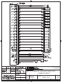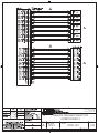
1
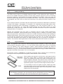
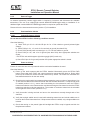
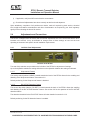
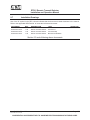
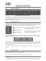
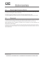
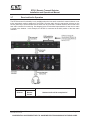
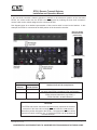
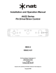
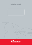
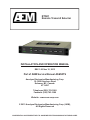
RTS01
Remote Transmit Selector
INSTALLATION AND OPERATION MANUAL
REV 1.00 Nov 15, 2013
Part of AEM Service Manual ASM-RTS
Anodyne Electronics Manufacturing Corp.
15-1925 Kirschner Road
Kelowna, BC, Canada.
V1Y 4N7
Telephone (250) 763-1088
Facsimile (250) 763-1089
Website: www.aem-corp.com
© 2013 Anodyne Electronics Manufacturing Corp. (AEM),
All Rights Reserved
CONFIDENTIAL AND PROPRIETARY TO ANODYNE ELECTRONICS MANUFACTURING CORP.
RTS01 Remote Transmit Selector
Installation and Operation Manual
COPYRIGHT STATEMENT
© 2013 Anodyne Electronics Manufacturing Corp. (AEM), All Rights Reserved
This publication is the property of AEM and is protected by Canadian copyright laws.
No part of this document may be reproduced or transmitted in any form or by any
means including electronic, mechanical, photocopying, recording, or otherwise, without
the prior written permission of AEM.
Installation and Operation Manual
Page ii
ENG-FORM: 820-0100.DOTX
CONFIDENTIAL AND PROPRIETARY TO ANODYNE ELECTRONICS MANUFACTURING CORP.
RTS01 Remote Transmit Selector
Installation and Operation Manual
Prepared By:
Checked By:
Duane Stewart
Designer
Nov 19/13
Nikolis Andrews
Designer
Nov 18, 2013
Approved By:
Tom Betzelt
Product Support
Manager
Nov. 19th, 2013
Todd Blackstock
R&D Manager
Nov 19/13
The status of this installation and operation manual is controlled by the revision shown on the title page.
The status of each section is controlled by revision shown in the footer of each page. All revisions
affecting sections of this manual have been incorporated.
AEM MANUAL REVISIONS
Section
Revision Number
Revision Description
Date
All
Rev: 1.00
Initial release
Nov 15, 2013
Installation and Operation Manual
Page iii
ENG-FORM: 820-0100.DOTX
CONFIDENTIAL AND PROPRIETARY TO ANODYNE ELECTRONICS MANUFACTURING CORP.
RTS01 Remote Transmit Selector
Installation and Operation Manual
Table of Contents
Section
Title
1.0
Description
1.1
1.2
1.3
1.4
1.4.1
1.4.1.1
1.4.1.2
1.4.1.3
1.4.1.4
1.4.2
1.4.3
Introduction
Product Description
Features
Specifications
Electrical Specifications
Input Operating Voltage
Input Power Requirements
Input Signals
Output Signals
Physical Specifications
Environmental Specifications
2.0
Installation
2.1
2.2
2.2.1
2.3
2.3.1
2.3.2
2.3.3
2.3.4
2.3.5
2.3.6
2.3.6.1
2.3.6.2
2.4
2.4.1
2.4.1.1
2.4.1.2
2.4.1.3
2.4.2
2.4.2.1
2.4.2.2
2.4.2.3
2.5
2.5.1
2.5.2
2.6
2.7
Introduction
Unpacking and Inspection
Warranty
Installation Procedures
Warnings
Cautions
Cabling and Wiring
Legend Installation
External Toggle
Post-Installation Checks
Voltage and Resistance Checks
Power on Checks
Adjustments and Connections
Left Side Panel Adjustments
Wrap around Feature
RX ACTIVE Detection Feature
RX Only Feature
Right Side Panel Adjustments
Maximum Transceiver Selection
RX ACTIVE Detection Threshold Adjustment
Tone Volume Adjustment
Accessories Required But Not Supplied
Installation kits
Snap in Legends
Continued Airworthiness
Installation Drawings
Installation and Operation Manual
Page
1-1
1-1
1-2
1-2
1-2
1-2
1-2
1-3
1-4
1-5
1-5
2-1
2-1
2-1
2-1
2-1
2-1
2-2
2-2
2-3
2-3
2-3
2-3
2-4
2-4
2-4
2-4
2-5
2-5
2-5
2-5
2-5
2-6
2-6
2-6
2-6
2-7
Page iv
ENG-FORM: 820-0100.DOTX
CONFIDENTIAL AND PROPRIETARY TO ANODYNE ELECTRONICS MANUFACTURING CORP.
RTS01 Remote Transmit Selector
Installation and Operation Manual
3.0
Operation
3.1
3.2
3.3
3.3.1
3.3.2
3.3.3
3.4
3.5
3.6
3.7
3.8
3.9
Introduction
General
Controls and Indicators
Power
Faceplate Backlighting
Faceplate Annunciators
Snap-in Legends
External Toggle & Transceiver Selection
Wrap-around
Received Audio Operation
RX ONLY
RX ACTIVE Detection
Installation and Operation Manual
3-1
3-1
3-1
3-1
3-2
3-2
3-2
3-3
3-3
3-4
3-6
3-6
Page v
ENG-FORM: 820-0100.DOTX
CONFIDENTIAL AND PROPRIETARY TO ANODYNE ELECTRONICS MANUFACTURING CORP.
RTS01 Remote Transmit Selector
Installation and Operation Manual
Section 1.0 Description
1.1
Introduction
Information in this section consists of product description, design features and specifications for the
RTS01 Remote Transmit Selector. All derivative product information will be contained in the applicable
manual supplement, which may be obtained from AEM as required.
Review all notes, warnings and cautions.
1.2
Product Description
RTS01 Faceplate with reference legends
The RTS01 is a powerful communications tool that can be used to add new capability and function to any
existing analog audio system. It offers three distinct operator benefits; Remote Transmit Select (RTS), RX
Activity Indication, and Audio System Expansion. Installation is designed to be simple, so there is little to
no impact on the existing audio system wiring.
The aircraft cockpit can be a very busy place, especially when your mission demands your full attention
and having both hands busy with the flight controls. Having to release one of those controls to reach over
and change the Transmit Select position on your audio panel can be more than an ‘inconvenience’. The
Remote Transmit Select capability of the RTS01 can be used to help address this situation. Use of an
existing or added ‘toggle switch’ on one of the flight controls is all that is needed to utilize the RTS
functions, once the pilot/operator has set the audio panel for RTS operations. Selection of the transceiver
is indicated by the annunciator above the respective transceiver legend. If you need to change radios,
you simply toggle the control-mounted RTS selector switch up or down until the desired annunciator is
illuminated.
Another issue many pilot/operators are faced with is the number of communication radios they have on
board to meet the mission requirements, and trying to determine which radio they are actually listening to
at any one time. The RX ACTIVE feature of the RTS01 can be used to solve this problem. This is a
simple ‘RX’ annunciator that illuminates to show which radio(s) are actively receiving communications,
and functions regardless of whether or not the operator has that particular radio audio input selected ‘on’
at the audio panel.
The trend towards a higher number of communication radios in aircraft is rapidly exceeding the
capacity of the audio systems that were fit as standard equipment in many different aircraft. The RTS01’s
‘expansion’ capability allows additional transceivers to be added to the communication system without
having to remove and replace the entire audio system.
Snap-in legends on the RTS01 provide the ability to custom label the transceiver channels.
Nov 15, 2013 Rev: 1.00
Page 1-1
ENG-FORM: 800-0100.DOTX
CONFIDENTIAL AND PROPRIETARY TO ANODYNE ELECTRONICS MANUFACTURING CORP.
RTS01 Remote Transmit Selector
Installation and Operation Manual
1.3
Features
Use of an existing or added ‘toggle switch’ to the flight controls provides hands free transceiver selection.
See section 2.3.5 or the interconnect document in section 2.7 for more information.
The RX ACTIVE detection feature illuminates a RX annunciator under the transceivers legend indicating if
a transceiver is currently receiving an audio signal. See section 2.4.1.2 for installation and section 3.6.3
for operation.
The RTS01 may be incorporated as an expansion panel with support for up to 7 transceivers. See section
2.4.2.1 for Maximum transceiver selection information.
An incorporated Wrap-around feature can be enabled for incrementing and decrementing the transceiver
selection. See section 2.4.1.1 for more information.
The RX ONLY feature allows received audio for com 5, 6, and 7 to be monitored individually, regardless
of which transceiver is selected by the operator. See section 2.4.1.3 for installation and section 3.6.2 for
operation.
The RTS01 front panel uses snap-in legends allowing the radio positions to be custom labeled. 7 snap-in
legends are required to operate the RTS01 and are not included. See section 2.3.4 for installation
information.
Some RTS01 models support night vision goggle (NVG) mode and as such are available with NVIS
Green A backlighting and NVIS Green B annunciators. Contact AEM for more information.
1.4
Specifications
1.4.1
Electrical Specifications
1.4.1.1
Input Operating Voltage
Normal Operating Conditions
Nominal
Maximum
Minimum
Emergency
Abnormal Operating Conditions
Nominal
Maximum
Minimum
1.4.1.2
+28 Vdc
+30.3 Vdc
+22.0 Vdc
+18.0 Vdc
+28 Vdc
+32.2 Vdc
+20.5 Vdc
Input Power Requirements
Nominal
Lighting
Nov 15, 2013 Rev: 1.00
400 mA max @ +28 Vdc
1.0 mA max @ +28 Vdc
1.0 mA max @ +5 Vdc
Page 1-2
ENG-FORM: 800-0100.DOTX
CONFIDENTIAL AND PROPRIETARY TO ANODYNE ELECTRONICS MANUFACTURING CORP.
RTS01 Remote Transmit Selector
Installation and Operation Manual
1.4.1.3
Input Signals
Microphone Audio
Quantity
Circuit Type
Rated Level
(MIC Outputs from Audio Controller)
7
Feedthrough/Passive
250 mVrms
RMT Microphone Audio
Quantity
Circuit Type
Rated Level
Impedance
(RMT MIC Outputs from Audio Controller)
1
Single ended
250 Vrms
150 Ω ±10% (fixed, AC impedance)
480 Ω ±10% (fixed, DC impedance)
12V dc (unloaded)
MIC Bias
Transceiver Receive Audio
Quantity
Circuit Type
Rated Level
Impedance
(COM RX from Transceivers)
7
Single ended
7.00 Vrms max
9.4 kΩ ±10%
Transmit Keylines
Quantity
(from Audio Controller)
7
RMT Transmit Keylines
Quantity
Rated Level
(RMT TX Keyline from Audio Controller)
7
Active Lo(≤ 11.5 Vdc)
Remote Transmit Select
Quantity
.
Rated Level
2 (RMT UP, RMT DN)
Active Lo(≤ 11.5 Vdc)
NVG Mode
Quantity
Rated Level
1
Active Lo(≤ 11.5 Vdc)
Nov 15, 2013 Rev: 1.00
Page 1-3
ENG-FORM: 800-0100.DOTX
CONFIDENTIAL AND PROPRIETARY TO ANODYNE ELECTRONICS MANUFACTURING CORP.
RTS01 Remote Transmit Selector
Installation and Operation Manual
1.4.1.4
Output Signals
Microphone Audio
Quantity
Circuit Type
Rated Level
Freq Response
Distortion
Audio Noise Level
(MIC Outputs to Transceivers)
7
Single ended
250 Vrms nominal into 150 Ω
<3 dB from 300 Hz to 6 kHz
< 10%@ Rated output
< 3% @ 10% of Rated Power output
Without Signal >60 dB below rated output
Transceiver Receive Audio
Quantity
Circuit Type
Rated Level
(COM RX to Audio Controller)
7
Feedthrough/Passive
7.00 Vrms into 1 kΩ
RMT Transceiver Receive Audio
Quantity
Circuit Type
Rated Level
Freq Response
Distortion
(RMT COM RX to Audio Controller)
1
Single ended
7.00 Vrms into 1 kΩ
<3 dB from 300 Hz to 6 kHz
< 10%@ Rated output
< 3% @ 10% of Rated Power output
Without Signal >60 dB below rated output
Audio Noise Level
Transmit Keylines
Quantity
Circuit type
Rated Level
Nov 15, 2013 Rev: 1.00
(to Transceivers)
7
Open drain
Active <100Ω to power ground
Inactive > 1 MΩ to power ground
Page 1-4
ENG-FORM: 800-0100.DOTX
CONFIDENTIAL AND PROPRIETARY TO ANODYNE ELECTRONICS MANUFACTURING CORP.
RTS01 Remote Transmit Selector
Installation and Operation Manual
1.4.2
Physical Specifications
Height
0.75" (19.05 mm) max
Depth
4.56" (115.8 mm) max behind panel, including connectors
5.00” (127.0 mm) max overall
Width
5.00" (127.0 mm) max behind panel
5.75" (146.1 mm) max in front of panel
Weight
0.8 lbs. (0.36 kg) max
Mounting
Standard Dzus Mounting (four fasteners)
Faceplate
Lexan polycarbonate
Connectors
1 x 44 pin D-sub Plug (male)
1 x 44 pin Dsub socket (female)
V5 locking hardware
Material/finish
Chassis & cover are brushed aluminum with chromate
conversion
1.4.3
Environmental Specifications
Temperature
-40 to +70qC (operating)
-55 to +85qC (survival)
Altitude
35,000 feet max.
Humidity
95% @ 50qC for 48 Hrs.
Shock
6g for 11ms
End of Section 1.0
Nov 15, 2013 Rev: 1.00
Page 1-5
ENG-FORM: 800-0100.DOTX
CONFIDENTIAL AND PROPRIETARY TO ANODYNE ELECTRONICS MANUFACTURING CORP.
RTS01 Remote Transmit Selector
Installation and Operation Manual
Section 2.0 Installation
2.1
Introduction
Information in this section consists of: unpacking and inspection procedures, installation procedures,
post-installation checks, and installation drawings.
2.2
Unpacking and Inspection
Unpack the equipment carefully. Inspect the unit visually for damage due to shipping and report all such
claims immediately to the carrier involved. Note that each unit should have the following:
- RTS01-001
- Product Information Card
- Certificate of Conformity or Release Certificate
Verify that all items are present before proceeding and report any shortage immediately to your supplier.
2.2.1
Warranty
All Anodyne Electronics Manufacturing Corp. (AEM) products are warranted for 2 years. See the website
www.aem-corp.com/warranty for complete details.
2.3
Installation Procedures
2.3.1
Warnings
WARNING:
High volume settings can cause hearing damage.
Set the headset volume control to the minimum volume setting prior to
conducting tests, and slowly increase the headset volume to a
comfortable listening level.
2.3.2
Cautions
CAUTION:
In all installations, use shielded cable exactly as shown and grounded as
indicated. Significant problems may result.
Nov 15, 2013 Rev: 1.00
Page 2-1
ENG-FORM: 805-0100.DOTX
CONFIDENTIAL AND PROPRIETARY TO ANODYNE ELECTRONICS MANUFACTURING CORP.
RTS01 Remote Transmit Selector
Installation and Operation Manual
2.3.3
Cabling and Wiring
The RTS01 must be wired to an available transceiver position of the existing host audio controller. If
there are no available transceiver positions, the host audio controller must give up one of its existing
transceiver positions to accommodate the electrical installation of the RTS01. If this is the case, the
transceiver position that was given up can be added to the RTS01. Other than information described in
this paragraph, the RTS01 does not affect the functionality of the existing host audio controller in any
way.
All wire shall be selected in accordance with the original aircraft manufacturer's Maintenance Instructions
or AC43.13-1B Change 1, Paragraphs 11-76 through 11-78. Unshielded wire types shall qualify to MILW-22759 as specified in AC43.13-1B Change 1, Paragraphs 11-85, 11-86, and listed in Table 11-11. For
shielded wire applications, use Tefzel MIL-C-27500 shielded wire with solder sleeves (for shield
terminations) to make the most compact and easily terminated interconnect. Follow the interconnect
drawing in section 2.7 as required.
Maintain wire segregation and route wiring in accordance with the original aircraft manufacturers
Maintenance Instructions. Unless otherwise noted, all wiring shall be a minimum of 24 AWG, except
power and ground lines, which shall be a minimum of 22 AWG. Reference the Interconnect drawing for
additional specifications. Check that the ground connection is clean and well secured, and that it shares
no path with any electrically noisy aircraft accessories such as blowers, turn and bank instruments or
similar loads. Microphone and keylines use twisted shielded pair. Do not ground LO connections to
airframe. The maximum cable length between RTS01 and the associated audio controller is 15ft (5m).
2.3.4
Legend Installation
Note: The legends for the transceiver channel labeling must be consistent on each RTS01 within a
communications management system (i.e. on each aircraft). Blank legend plates (Part no.155-06-000)
are to be installed in any unused transceiver location. Unused transceiver positions are limited to
transceivers 5, 6, and 7 with the first disabled transceiver being transceiver 7 followed subsequently by
transceiver 6 and 5. It is recommended to disable unused transceivers using the switch located on the
right side of the RTS01. See section 2.4.2.1 for more details.
Each RTS01 requires a minimum of 7 individually purchased snap-in legends (Part no.155-06-xxx).
Each legend comes complete with a black gasket, either attached or loose in the bag.
When installing the legends for the first time, each legend must be
fitted with a black gasket to eliminate light leakage around the
legend. The gasket fits into place on the back of the legend, but is
easily dislodged or damaged. Take particular care to ensure that it is
properly positioned before snapping the legend fully into place. If a
replacement gasket is required, the whole legend must be ordered.
If it is necessary to remove or replace a legend, carefully pry either
end of the legend up and out of the faceplate, and insert the new or
replacement legend as described above. Avoid using metal or sharp
objects when removing legends.
CAUTION:
If the faceplate is damaged in any way during this process, light leakage may occur, which will
necessitate returning the unit to the manufacturer for repair or replacement.
Nov 15, 2013 Rev: 1.00
Page 2-2
ENG-FORM: 805-0100.DOTX
CONFIDENTIAL AND PROPRIETARY TO ANODYNE ELECTRONICS MANUFACTURING CORP.
RTS01 Remote Transmit Selector
Installation and Operation Manual
2.3.5
External Toggle
An external momentary contact toggle switch is required to increment and decrement the available
transceivers. The use of an existing flight controls MOM-OFF-MOM toggle switch or installation of an
additional flight controls MOM-OFF-MOM toggle switch is required to operate the RTS01.
Please refer to the interconnect document (section 2.7) for installation.
2.3.6
Post-Installation Checks
2.3.6.1
Voltage/Resistance Checks
Do not attach the RTS01 until the following conditions are met.
Check the following:
a) Check P102, pin <5> for +28 Vdc OR pin <6> for +5 Vdc relative to ground (selected lights
voltage).
b) Check P102 pin <2>, <3>, and <4> for continuity to ground (less than 0.5:).
c) Check P102 (aircraft power connector) pin <1> for +28 Vdc relative to ground.
d) Check P102 pin <9>, and <10> for ground (less than 0.5:) when appropriate switches are
closed.
**For RTS01 units which support night vision goggle (NVG) mode only.
e) Check P102 pin <8> for ground (less than 0.5:) when appropriate switch is closed.
2.3.6.2
Power on Checks
Ensure all connectors are securely fastened and the mechanical installation is sound.
Check the following:
a) Power up the audio systems with the RTS01 installed. Momentarily press the RTS01 PWR
button. Ensure the green ‘PWR’ and a green transceiver annunciator are both on. During initial
power up the RTS01 will choose the first transceiver by default. The RTS01 will remember the
last selected transceiver for the next startup.
b) Check that the toggle switch increments and decrements the correct number of transceivers (4 to
7) and ensure that all annunciators illuminate with the selected transceiver. If wrap-around mode
is enabled (section 2.4.1.1), ensure that incrementing the last transceiver sets the RTS01’s
transceiver selection to the first transceiver and decrementing the first transceiver sets the RTS01
transceiver selection to the last transceiver. The number of maximum transceivers is selectable
on the right side of the RTS01 (section 2.4.2.1).
c) Verify that audio is being received and sent to the transceivers correctly through each of the
channels.
d) Verify that a single audible tone is heard while switching transceivers and a dual audible tone is
heard on the first and last transceiver. If Wrap-around mode is enabled, only a single audible tone
is heard.
e) Check that turning on the panels lights will backlight the RTS01 snap-in legends and dim the
faceplate annunciators.
Nov 15, 2013 Rev: 1.00
Page 2-3
ENG-FORM: 805-0100.DOTX
CONFIDENTIAL AND PROPRIETARY TO ANODYNE ELECTRONICS MANUFACTURING CORP.
RTS01 Remote Transmit Selector
Installation and Operation Manual
f)
If applicable, verify that NVG mode dims the annunciators.
g) Check that all adjustments have been correctly set before aircraft departure.
Upon satisfactory completion of all performance checks, make all required log book entries, electrical
load, weight and balance amendments and other documentation as required by your local regulatory
agency before releasing the aircraft for service.
2.4
Adjustments and Connections
The RTS01 is shipped from the factory with all internal adjustments set to the normal test levels. Once
installed in the aircraft, it may be desirable to change some of these settings to best suit the local
operating environment and specific aircraft installation requirements.
2.4.1
Left Side Panel Adjustments
Left Side of the RTS01
Two sets of dip switches are provided on the left side of the RTS01 for adjustment of settings.
Up on the dipswitch enables the setting while down on the dipswitch disables the setting as indicated.
2.4.1.1
Wrap-around Feature
The first dip switch (labeled “WRAP”) located towards the back of the RTS01 allows for the enabling and
disabling of the Wrap-around feature. See section 3.6.
.
Default positioning for the Wrap-around feature is disabled.
2.4.1.2
RX ACTIVE Detection Feature
The second dip switch (labeled “RX DET”) located towards the back of the RTS01 allows the enabling
and disabling of the RX ACTIVE Detection feature. See section 3.9 for the operation of the RX ACTIVE
detection feature.
The detection threshold for the RX ACTIVE feature is further detailed in section 2.4.2.2.
Default positioning for the RX detection feature is enabled.
Nov 15, 2013 Rev: 1.00
Page 2-4
ENG-FORM: 805-0100.DOTX
CONFIDENTIAL AND PROPRIETARY TO ANODYNE ELECTRONICS MANUFACTURING CORP.
RTS01 Remote Transmit Selector
Installation and Operation Manual
2.4.1.3
RX ONLY Feature
The second set of dip switches allows for the individual transceiver selection for the RX Only feature. The
individual transceivers are labeled above the dip switch with COM 5 being transceiver 5 respectively.
See section 3.8 for the operation of the RX only feature.
Default positioning for all 3 RX ONLY dip switches is disabled.
*The dip switch labeled RSV is a reserved switch and provides no functional changes to the device.
2.4.2
Right Side Panel Adjustments
Right side of the RTS01
One rotary switch and two potentiometers are provided on the right side of the RTS01 for the adjustment
of settings.
2.4.2.1
Maximum Transceiver Selection
The rotary switch labeled “MAX COMS” is for selecting the maximum number of transceivers. The
maximum number of transceivers may be adjusted from 4 to 7. Unused transceivers on the RTS01 are
restricted to COM 5, 6, and 7 positions.
Example: If only 5 transceivers are used, transceivers 1 through 5 from left to right will be enabled.
Default positioning for MAX COMS is 7.
2.4.2.2
RX ACTIVE Detection Threshold Adjustment
The potentiometer closest to the front of the RTS01 and labeled “RX DET THRESHOLD” adjusts the RX
Activity Detection sensitivity for all 7 transceivers. Turning the potentiometer clockwise reduces sensitivity
while counterclockwise increases sensitivity.
Default positioning for the potentiometer is the mid position.
2.4.2.3
Tone Volume Adjustment
The potentiometer closest to the back of the RTS01 and labeled “TONE VOL” adjusts the transceiver
increment or decrement tone volume. This setting adjusts the tone of both the single and dual audio
tones. Turning the potentiometer clockwise increases volume while counterclockwise decreases volume.
Default positioning for the potentiometer is in the mid position.
Nov 15, 2013 Rev: 1.00
Page 2-5
ENG-FORM: 805-0100.DOTX
CONFIDENTIAL AND PROPRIETARY TO ANODYNE ELECTRONICS MANUFACTURING CORP.
RTS01 Remote Transmit Selector
Installation and Operation Manual
2.5
Accessories Required But Not Supplied
2.5.1
Installation Kits
Installation kit D44S44PV-IKC (crimp) is required to complete the installation. The kit consists of the
following:
Quantity
1
1
Description
44 Pin D-min Female Crimp Kit
44 Pin D-min Male Crimp Kit
AEM Part No.
D44SV-IKC
D44PV-IKC
D44SV-IKC consists of
Quantity
1
44
Description
*D-sub socket, Crimp, Locking
Contacts, Crimp, female
AEM Part No.
20-21-044
20-26-014
D44PV-IKC consists of
Quantity
1
44
Description
*D-sub plug, Crimp, Locking
Contacts, Crimp, Male
AEM Part No.
20-11-044
20-26-704
*D-sub socket and plug include the required connector hood.
2.5.2
Snap-in Legends
The RTS01 requires 7 snap-in Legends to complete the installation. The 7 snap-in legends must be
purchased as separate items and are not included with the RTS01.
Quantity
-
Description
Blank Snap-in Legend
*Snap-in Legend
AEM Part No.
155-06-000
155-06-xxx
*Snap-in legend text is user specified. Please contact AEM for more information.
2.6
Continued Airworthiness
Maintenance of the RTS01 Remote Transmit Selector is ‘on condition’ only. Periodic maintenance of this
product is not required.
Nov 15, 2013 Rev: 1.00
Page 2-6
ENG-FORM: 805-0100.DOTX
CONFIDENTIAL AND PROPRIETARY TO ANODYNE ELECTRONICS MANUFACTURING CORP.
RTS01 Remote Transmit Selector
Installation and Operation Manual
2.7
Installation Drawings
Use of the "#" symbol in the REV. column indicates that the document is listed elsewhere in the manual.
Refer to the applicable AEM Part No. to locate the referenced document.
DOCUMENT
REV
DESCRIPTION
TYPE
RTS01-001-403-0
RTS01-001-405-0
RTS01-001-922-0
1.00
1.00
1.00
Remote Transmit Selector
Remote Transmit Selector
Remote Transmit Selector
Interconnect
Connector Map
Mechanical Installation
SERIAL NO.
Section 2.0 ends following above documents
Nov 15, 2013 Rev: 1.00
Page 2-7
ENG-FORM: 805-0100.DOTX
CONFIDENTIAL AND PROPRIETARY TO ANODYNE ELECTRONICS MANUFACTURING CORP.
KELOWNA BC CANADA
(250)-763-1088
WWW.AEM-CORP.COM
Nov 6/13
REMOTE TRANSMIT SELECTOR
INTERCONNECT
Nov 14/13
REV
SIZE
A
RTS01-001
L9015
1:1
403-0
1.00
SHEET 1 of 3
KELOWNA BC CANADA
(250)-763-1088
WWW.AEM-CORP.COM
Nov 6/13
REMOTE TRANSMIT SELECTOR
INTERCONNECT
Nov 14/13
REV
SIZE
A
RTS01-001
L9015
1:1
403-0
1.00
SHEET 2 of 3
KELOWNA BC CANADA
(250)-763-1088
WWW.AEM-CORP.COM
Nov 6/13
REMOTE TRANSMIT SELECTOR
INTERCONNECT
Nov 14/13
REV
SIZE
A
RTS01-001
L9015
1:1
403-0
1.00
SHEET 3 of 3
KELOWNA BC CANADA
(250)-763-1088
WWW.AEM-CORP.COM
Nov 6/13
REMOTE TRANSMIT SELECTOR
CONNECTOR MAP
Nov 14/13
REV
SIZE
A
RTS01-001
L9015
1:1
405-0
SHEET 1 of 1
1.00
8
6
7
5
4
2
3
1
5.00 127 MAX
0.25 6.4
2.44 62 EST.
D
4.33 110
5.00 127 MAX
D
C
0.44 11.2
2.06 52.3 EST.
C
B
B
5.75 146.1 MAX
COM2
VHF1
VHF2
0.75 19.1 MAX
COM1
A
TAC1
TAC2
NAME
DRAWN
WEIGHT: 0.8 lbs. (0.4 kg.) MAX
ADF
LAC
DATE
15-Nov-13
CHECKED
Nov 15/13
APPROVED
Nov 15/13
CONFIDENTIAL AND PROPRIETARY
7
6
N/A
5
4
15-1925 KIRSCHNER RD.
KELOWNA BC V1Y 4N7
(250)-763-1088
WWW.AEM-CORP.COM
A
TITLE:
REMOTE TRANSMIT SELECTOR
MECHANICAL INSTALLATION
INTERPRET GEOMETRIC
TOLERANCING PER:
N/A
RTS01 IS SHIPPED FROM THE FACTORY WITHOUT THE LEGENDS INSTALLED.
8
DIMENSIONS ARE IN INCHES
TOLERANCES:
FRACTIONAL 0.5 Deg
BEND
ANGULAR: MACH
TWO PLACE DECIMAL
0.10
THREE PLACE DECIMAL 0.005
THE INFORMATION CONTAINED IN THIS
MATERIAL
DRAWING IS THE SOLE PROPERTY OF
ANODYNE ELECTRONICS MANUFACTURING.
ANY REPRODUCTION IN PART OR AS A WHOLE FINISH
WITHOUT THE WRITTEN PERMISSION OF
ANODYNE ELECTRONICS MANUFACTURING IS
PROHIBITED.
DO NOT SCALE DRAWING
NOTES:
1.
UNLESS OTHERWISE SPECIFIED:
3
SIZE
B
CAGE CODE
DWG. NO.
RTS01-001
.
SCALE: 1:1
REV
WEIGHT:
922-0
2
1.00
SHEET 1 OF 1
1
RTS01 Remote Transmit Selector
Installation and Operation Manual
Section 3.0 Operation
3.1
Introduction
Information in this section consists of functional and operational procedures for the RTS01 Remote
Transmit Selector.
3.2
General
The RTS01 is a powerful communications tool that can be used to add new capability and function to any
existing analog audio system. It offers three distinct operator benefits; Remote Transmit Select (RTS), RX
Activity Indication, and Audio System Expansion. Installation is designed to be simple, so there is little to
no impact on the existing audio system wiring.
The aircraft cockpit can be a very busy place, especially when your mission demands your full attention
and having both hands busy with the flight controls. Having to release one of those controls to reach over
and change the Transmit Select position on your audio panel can be more than an ‘inconvenience’. The
Remote Transmit Select capability of the RTS01 can be used to help address this situation. Use of an
existing or added ‘toggle switch’ on one of the flight controls is all that is needed to utilize the RTS
functions, once the pilot/operator has set the audio panel for RTS operations. Selection of the transceiver
is indicated by the annunciator above the respective transceiver legend. If you need to change radios,
you simply toggle the control-mounted RTS selector switch up or down until the desired annunciator is
illuminated.
Another issue many pilot/operators are faced with is the number of communication radios they have on
board to meet the mission requirements, and trying to determine which radio they are actually listening to
at any one time. The RX ACTIVE feature of the RTS01 can be used to solve this problem. This is a
simple ‘RX’ annunciator that illuminates to show which radio(s) are actively receiving communications,
and functions regardless of whether or not the operator has that particular radio audio input selected ‘on’
at the audio panel.
The trend towards a higher number of communication radios in aircraft is rapidly exceeding the
capacity of the audio systems that were fit as standard equipment in many different aircraft. The RTS01’s
‘expansion’ capability allows additional transceivers to be added to the communication system without
having to remove and replace the entire audio system.
Snap-in legends on the RTS01 provide the ability to custom label the transceiver channels.
3.3
Controls & Indicators
3.3.1
Power
A momentary push button power switch is provided on the RTS01 to power on and off the unit. While
powered on, the “PWR” annunciator will illuminate green below the power switch. The annunciator above
the currently selected transceiver will also illuminate.
Nov 15, 2013 Rev: 1.00
Page 3-1
ENG-FORM: 806-0100.DOTX
CONFIDENTIAL AND PROPRIETARY TO ANODYNE ELECTRONICS MANUFACTURING CORP.
RTS01 Remote Transmit Selector
Installation and Operational Manual
3.3.2
Faceplate Backlighting
RTS01 Faceplate with reference legends.
The illumination of the RTS01 snap-in legends is linked to the aircraft faceplate dimming buss. When
backlighting is on, all snap-in legends will illuminate standard white to a level proportional to the aircraft
dimming buss voltage. See section 3.3.3 for information on the RTS01 annunciators. When backlighting
is off, all snap-in legends are not illuminated.
3.3.3
Faceplate Annunciators
Annunciators are LED indicators that illuminate to indicate currently selected states or provide operator
feedback. Two types of annunciators are incorporated into the faceplate of the RTS01. The first being the
selected transceiver annunciator and the second being the receive indication annunciator.
The transceiver annunciator illuminates green
above the snap-in legend to indicate the
currently selected transceiver.
The ‘RX’ annunciators illuminate green below
the snap-in legends to show which channels are
currently receiving an audio signal.
There are 2 brightness levels for the annunciators that are defined as day mode and night mode. These
modes are automatically selected within the RTS01 by sensing the voltage on the aircraft dimming buss,
as described in the table below:
Day Mode
Night Mode
5V Dimming Buss
< 1.4 Vdc
> 1.4 Vdc
28V Dimming Buss < 5.3 Vdc
> 5.3 Vdc
For NVIS models, there is a third brightness level defined as NVG mode, which is dimmer than night
mode. NVG mode is activated by grounding pin 8 of J102 on the RTS01 through an external switch.
When NVG mode is activated, the annunciator brightness level is fixed regardless of the voltage present
on the aircraft dimming buss.
A version of the RTS01 that supports night vision goggle (NVG) mode is available. Contact AEM for more
information.
3.4
Snap-in Legends
Snap-in legends for each of the 7 possible transceivers provide the ability to customize the individual
transceiver labels to match the radios on the aircraft.
Blank snap-in legends should be inserted in any unused transceiver positions.
Nov 15, 2013 Rev: 1.00
Page 3-2
ENG-FORM: 806-0100.DOTX
CONFIDENTIAL AND PROPRIETARY TO ANODYNE ELECTRONICS MANUFACTURING CORP.
RTS01 Remote Transmit Selector
Installation and Operation Manual
3.5
External Toggle & Transceiver Selection
The RTS01 remotely controls up to 7 transceivers by utilizing an external MOM-OFF-MOM toggle switch
to remotely scroll through the available transceivers.
The RTS01 provides an audible tone to indicate a transceiver change has been made.
The external toggle switch is ideally mounted on or currently installed in the flight controls of the aircraft.
3.6
Wrap-around
The RTS01 includes a Wrap-around feature. When enabled, this feature allows the operator to cycle back
to the first transceiver by simply incrementing past the last selectable transceiver, and vice versa.
While Wrap-around mode is disabled, the RTS01 will only increment to the last transceiver and
decrement to the first transceiver.
If Wrap-around mode is enabled, a single tone audio signal will be heard with each transceiver selection.
When Wrap-around mode is disabled, a two tone audio signal will be heard with the selection of the first
and last transceivers.
Nov 15, 2013 Rev: 1.00
Page 3-3
ENG-FORM: 806-0100.DOTX
CONFIDENTIAL AND PROPRIETARY TO ANODYNE ELECTRONICS MANUFACTURING CORP.
RTS01 Remote Transmit Selector
Installation and Operational Manual
3.7
Received Audio Operation
The RTS01 transmit functionality is only available when the host audio controller’s transmit selector is set
to the transceiver position assigned to the RTS01. Receive audio from the transceiver selected on the
RTS01 (Auto-RX) is summed with receive audio from any RX ONLY enabled channels and routed to the
host audio controller for monitoring. See diagram below for a detailed representation of how receive audio
is routed to the headset. In this example, the RTS01 is connected to the AUX position of the host audio
controller.
Host Audio Controller
TX
AUX RX
Selector
Monitor
Switch
AUX
Don’t care
Nov 15, 2013 Rev: 1.00
Headset Audio will be comprised of
RTS01 COM2 + RTS01 RX ONLY enabled channels
Page 3-4
ENG-FORM: 806-0100.DOTX
CONFIDENTIAL AND PROPRIETARY TO ANODYNE ELECTRONICS MANUFACTURING CORP.
RTS01 Remote Transmit Selector
Installation and Operation Manual
If the host audio controller’s transmit selection is not set to the transceiver position of the connected
RTS01, the receive audio from the RTS01 can be monitored by enabling the host audio controller’s
receive audio monitor switch assigned to the connected RTS01.
See diagram below for a detailed representation of how receive audio is routed to the headset. In this
example, the RTS01 is connected to the AUX position of the host audio controller.
Receive Audio
monitor Switch
positioning
RX-ON down (off)
RX-ON up (on)
Host Audio Controller
TX
AUX RX
Selector
Monitor Switch
COM2
DOWN
COM2
UP
Headset Audio will be comprised of
COM2 from host audio controller only
(No audio from RTS01 regardless of RX annunciation)
COM2 from host audio controller +
RTS01 selected transceiver (eg: COM1) +
RTS01 RX ONLY enabled channels
CAUTION:
The RTS01 transceiver annunciator will not correctly represent the selected
transceiver if the host audio controller’s transmit selector is not set to the
transceiver position assigned to the RTS01. Communication selection will be
from the host audio controller only. If desired the RTS01 can be powered off
to avoid confusion.
Nov 15, 2013 Rev: 1.00
Page 3-5
ENG-FORM: 806-0100.DOTX
CONFIDENTIAL AND PROPRIETARY TO ANODYNE ELECTRONICS MANUFACTURING CORP.
RTS01 Remote Transmit Selector
Installation and Operational Manual
3.8
RX ONLY
The RX ONLY feature allows received audio to be monitored for up to 3 transceivers (COMs 5, 6 and 7)
by the operator regardless of which transceiver is selected on the RTS01. This feature can be enabled or
disabled individually for COMs 5, 6, and 7.
3.9
RX ACTIVE Detection
When enabled, the RX ACTIVE Detection allows for the viewing of all actively receiving channels.
When a channel is receiving an audio signal the corresponding green RX annunciator will illuminate
regardless of which transceiver is selected on the RTS01.
Note: When enabled, the RX annunciators will illuminate regardless of the transceiver selector switch
position or receive audio monitor switch position of the host audio controller.
End of Section 3.0
Nov 15, 2013 Rev: 1.00
Page 3-6
ENG-FORM: 806-0100.DOTX
CONFIDENTIAL AND PROPRIETARY TO ANODYNE ELECTRONICS MANUFACTURING CORP.