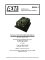
1
SPECIAL NOTICE
This product is now licensed to Anodyne Electronics Manufacturing (AEM) from Northern
Airborne Technology (NAT). AEM is responsible for all matters related to this product, including
sales, support and repair services.
Please note the transition to convert product manuals and supporting documentation is an
ongoing process and is being addressed on an ‘as needed’ basis.
All references to NAT product part numbers (and associated images) are equivalent to AEM
product part numbers.
Contact info:
Anodyne Electronics Manufacturing Corp.
#15-1925 Kirschner Road
Kelowna B.C. Canada
V1Y 4N7
Email: [email protected]
Toll Free: 1-888-763-1088
Phone: 1-250-763-1088
Fax: 1-250-763-1089
www.aem-corp.com
SM44-1
PA250 Series
High Power Voice Amplifier
INSTALLATION AND OPERATION MANUAL
Rev: 2.00 April 22, 2012
Anodyne Electronics Manufacturing Corp.
15-1925 Kirschner Road
Kelowna, BC, Canada.
V1Y 4N7
Telephone (250) 763-1088
Facsimile (250) 763-1089
Website: www.aem-corp.com
© 2012 Anodyne Electronics Manufacturing Corp. (AEM),
All Rights Reserved
CONFIDENTIAL AND PROPRIETARY TO ANODYNE ELECTRONICS MANUFACTURING CORP.
PA250 Series High Power Voice Amplifier
SM44-1 Installation and Operation Manual
COPYRIGHT STATEMENT
© 2012 Anodyne Electronics Manufacturing Corp. (AEM), All Rights
Reserved
This publication is the property of AEM and is protected by Canadian
copyright laws. No part of this document may be reproduced or transmitted
in any form or by any means including electronic, mechanical,
photocopying, recording, or otherwise, without the prior written permission
of AEM.
Installation and Operation Manual
Page ii
ENG-FORM: 820-0100.DOTX
CONFIDENTIAL AND PROPRIETARY TO ANODYNE ELECTRONICS MANUFACTURING CORP.
PA250 Series High Power Voice Amplifier
SM44-1 Installation and Operation Manual
Prepared By:
Checked By:
Approved By:
Tom Betzelt
Product Support
Manager
May 28, 2012
Loen Clement
Designer
May 24/12
Tony Pearson
Designer
Apr 22, 2012
The status of this installation and operation manual is controlled by issue shown on the title page. The
status of each section is controlled by revision shown in the footer of each page. All revisions affecting
sections of this manual have been incorporated into the latest issue.
ISSUE/REVISION RECORD
Manual Issue
Number
Section
Revision Number
Revision Description
Issue Date
4.02
Section 2 Rev: 1.01
Updated with the latest drawings.
Mar 10, 2009
4.01
Section 1 Rev: 1.00
Section 2 Rev: 1.00
Section 3 Rev: 1.00
Update to current templates.
Updated Section 2 with the latest
drawings.
Aug 13, 2008
AEM MANUAL REVISIONS
Section
Revision Number
Revision Description
Date
All
Rev 2.00
Updated drawings and template
April 22, 2012
Installation and Operation Manual
Page iii
ENG-FORM: 820-0100.DOTX
CONFIDENTIAL AND PROPRIETARY TO ANODYNE ELECTRONICS MANUFACTURING CORP.
PA250 Series High Power Voice Amplifier
SM44-1 Installation and Operation Manual
Table of Contents
Section
Title
1.0
Description
1.1
1.2
1.3
1.4
1.4.1
1.4.2
1.4.3
1.5
1.5.1
1.5.2
1.5.3
1.5.4
Introduction
Product Description
Design Features
Specifications
Electrical Specifications
Physical Specifications
Environmental Specifications
Auxiliary Components
Control Panel
Microphone
Loudspeakers
Power Supplies
2.0
Installation
2.1
2.2
2.2.1
2.3
2.4
2.4.1
2.4.2
2.4.3
2.4.4
2.4.5
2.4.6
2.5
2.5.1
2.5.2
2.5.3
2.5.4
2.5.5
2.5.6
2.6
2.6.1
2.6.2
2.6.3
2.6.4
2.7
Introduction
Unpacking and Inspection
Warranty
Continued Airworthiness
Installation Procedures
Cautions
Cabling and Wiring
Ground Site Selection
Aiborne Installation
Remote Installation
Post Installation Checks
Accessories
Dummy Load
Meter Test Set
Protective Circuit Test Unit
Paralleling Transformers
Remote Controls
Tape Recorders/Players
Accessories Required But Not Supplied
Power/Speaker Kit
Recorder Input Kit
Microphone Input Kit
Remote Input Kit
Installation Drawings
Installation and Operation Manual
Page
1-1
1-1
1-1
1-2
1-2
1-2
1-3
1-3
1-3
1-3
1-4
1-5
2-1
2-1
2-1
2-1
2-2
2-2
2-2
2-3
2-3
2-3
2-4
2-5
2-5
2-5
2-5
2-5
2-5
2-5
2-6
2-6
2-6
2-6
2-7
2-7
Page iv
ENG-FORM: 820-0100.DOTX
CONFIDENTIAL AND PROPRIETARY TO ANODYNE ELECTRONICS MANUFACTURING CORP.
PA250 Series High Power Voice Amplifier
SM44-1 Installation and Operation Manual
Section
Title
3.0
Operation
3.1
3.2
3.3
3.3.1
3.3.2
3.3.3
3.3.4
3.3.5
3.3.6
Introduction
General Information
Controls and Indicators
POWER Switch
POWER Lamp
GAIN Control
AUDIO POWER (Level) Meter
OVERLOAD Indicator LED
Resetting the Protective Circuit
Installation and Operation Manual
Page
3-1
3-1
3-1
3-1
3-2
3-2
3-3
3-3
3-3
Page v
ENG-FORM: 820-0100.DOTX
CONFIDENTIAL AND PROPRIETARY TO ANODYNE ELECTRONICS MANUFACTURING CORP.
PA250 Series High Power Voice Amplifier
SM44-1 Installation and Operation Manual
Section 1.0 Description
1.1
Introduction
Information in this section consists of product description, design features and specifications for the
PA250 Series High Power Voice Amplifier. All derivative product information shall be contained in the
applicable manual supplement, which may be obtained from AEM as required.
Review all notes, warning and cautions.
1.2
Product Description
The completely transistorized PA250 Series provides the basis for a portable, high gain tactical sound system.
It is designed to provide point-to-point dissemination of sound in application use over land, water or from the
air. The maximum useable range is greater than one mile when operated from a favourable vantage point.
The nominal rated audio power output is 250 watts with 28 Vdc input power.
Note:
1.3
In airborne applications, the amplifier is normally remote-mounted in the avionics bay and the PA250
Series controls are not operator accessible. Any necessary adjustments must be made at the time of
installation.
Design Features
The PA250 Series amplifier is a 250 watt completely transistorized unit constructed in a rugged, black
anodized, aluminum chassis. Its reliability is enhanced by conservative design and a unique built-in
protective circuit, which shuts off the amplifier whenever excessive input or operating conditions threaten
to impair vital circuit elements.
The PA250 Series contains protective circuits, which operate to protect the semiconductor components
from the following conditions:
a) Reverse polarity
b) Excessive current or voltage
c) Internal or external short circuits
When the problem is transient or cleared, the protective circuit resets by the simple operation of the
power switch.
April 22, 2012 Rev: 2.00
Page 1-1
ENG-FORM: 800-0100.DOTX
CONFIDENTIAL AND PROPRIETARY TO ANODYNE ELECTRONICS MANUFACTURING CORP.
PA250 Series High Power Voice Amplifier
SM44-1 Installation and Operation Manual
1.4
Specifications
1.4.1
Electrical Specifications
Input Power
Supply Voltage
+24 to +36 Vdc normal
+28 Vdc max.
Supply Impedance
<0.05:
Supply Current
0.01 A @ +28 Vdc (no signal)
15-20 A @ +28 Vdc (full power out)
3 A @ +28 Vdc (voice operation)
Input Signals
The signal levels shown below are required for full amplifier drive at the points and impedances
shown.
JACK
PINS
IMPEDANCE
INPUT LEVEL
MIC
REC
REC
A-C
B-C
A-C
150 :
600 :
2000 :
0.005 Vrms
0.5 Vrms
1.0 Vrms
Output Signals
Output Power
250 watts into 1.75 :, with a 5 mVrms, 1 kHz signal applied to
the microphone input
Output Load Impedance
1.4 to 1.75 : each channel. (Nominal 2Ƿ)
Amplifier shut-down if load <1 :
Frequency Response
<3 dB over 500 to 5000 Hz
Harmonic Distortion
<10% at 40% rated power, with 1000 Hz sine wave input
1.4.2
Physical Specifications
Height
4.26” (108.3 mm) including controls
Depth
10.00” (254.0 mm) including mounting plate
9.17” (232.8 mm) excluding mounting plate
Width
8.75” (222.3 mm) including mounting plate
6.63” (168.4 mm) excluding mounting plate
Weight
6.75 lbs (3.06 kg)
April 22, 2012 Rev: 2.00
Page 1-2
ENG-FORM: 800-0100.DOTX
CONFIDENTIAL AND PROPRIETARY TO ANODYNE ELECTRONICS MANUFACTURING CORP.
PA250 Series High Power Voice Amplifier
SM44-1 Installation and Operation Manual
1.4.3
1.5
Environmental Specifications
Temperature
-35 to +60qC
Altitude
25,000 feet
Auxiliary Components
The PA250 Series amplifier is designed to operate with specific compatible components to form an
effective sound system.
1.5.1
Control Panel
1.5.1.1
AA21
The AA21 Cabin PA control unit is designed to provide centralized control for an aircraft’s internal and
external PA systems. The unit is Dzus mounted with an illuminated faceplate and a front panel switch to
provide selection of the various operational modes. The AA21 provides two low level audio signal outputs
that drive the input on remote mounted power amplifiers. One output is designed to drive the PA110/220
series amplifiers and the other output is designed to drive the PA250/700 series amplifiers.
1.5.1.2
AA22
The AA22 PA/Siren control unit is a compact, self contained, Dzus mounted unit for use with the PA250
and PA700 series audio power amplifiers. It has a low level output rated at 500 mVrms. It provides a
centralized control for external audio paging and siren functions.
1.5.1.3
PM01-001
The PM01-001 is a remote control device designed as the operating station for a high power audio
system. The PM01-001 is equipped with two decibel meters which make it ideal for monitoring either one
or two power amplifiers.
1.5.2
Microphone
1.5.2.1
PM03-002
The PM03-002 is a hand-held, dynamic and noise-cancelling microphone with a push-to-talk button. It
comes with a coiled retractable cable and connector for direct connection to the amplifier or remote
control unit such as the PM01-001.
April 22, 2012 Rev: 2.00
Page 1-3
ENG-FORM: 800-0100.DOTX
CONFIDENTIAL AND PROPRIETARY TO ANODYNE ELECTRONICS MANUFACTURING CORP.
PA250 Series High Power Voice Amplifier
SM44-1 Installation and Operation Manual
1.5.3
Loudspeakers
Various types of loudspeaker arrays can be used in sounds systems using the PA250/700 amplifiers.
They are identified by the style and number of drivers (and bells) in each speaker array as shown in Table
1. As a guideline for system configuration, there should be a minimum of 1 speaker driver/bell assembly
for each 100 watts of amplifier power.
Part No.
Description
TS92-02XN
Standard two-bell array with drivers
TS92-04XN
TS93-04XN
TS94-04XN
Standard four-bell array with drivers
Standard four-bell cloverleaf array with drivers
Standard four-bell mini speaker array with drivers
Table 1
Speaker Arrays
For comparison, the efficiencies of the four-bell speakers are shown in Table 2 (assuming the same input
power is delivered to each type).
Part No.
Description
Efficiency
TS92-02XN
TS92-04XN
Standard two-bell array with drivers
Standard four-bell array with drivers
100%
195%
Table 2
Efficiencies
The higher efficiency rating is due to more concentrated sound patterns and lower, more efficient power
conversion at each speaker driver. The larger speakers can also accept more power from the amplifying
system and may show an even better efficiency rating than these figures indicate.
1.5.3.1
TS92-02XN
The two-bell speaker array is widely used in airborne applications where its light weight and small size
are important considerations. While its output efficiency is not equal to that of the larger loudspeaker
types, it performs well on small and medium-sized aircraft. The size and weight of the two-bell speaker
often permits it to become a permanent installation in the aircraft.
1.5.3.2
TS92-04XN
The four-bell loudspeaker is almost universally chosen for portable sound systems.
efficiency compensates for the additional weight compared to the two-bell speaker.
1.5.3.3
The greater
Multiple Speakers
The TS9X is designed to be assembled in groups of two, four or more. This permits the use of multiple
amplifying systems for higher sound levels and greater distance.
April 22, 2012 Rev: 2.00
Page 1-4
ENG-FORM: 800-0100.DOTX
CONFIDENTIAL AND PROPRIETARY TO ANODYNE ELECTRONICS MANUFACTURING CORP.
PA250 Series High Power Voice Amplifier
SM44-1 Installation and Operation Manual
1.5.4
Power Supplies
Power can be supplied by storage batteries, electronic supplies or vehicle/aircraft power systems.
Vehicle supplies of 24 – 28 Vdc are an obvious choice for most airborne/mobile installations. The 12 – 14
Vdc supply of the commercial vehicle can not be used.
In the hand-pack series, sealed nickel cadmium cells are used. Adding extra cells can almost double the
available power.
Electronic power supplies are frequently used in maintenance shops and fixed installations. A minimum
requirement would be a well regulated supply of 20 - 40 Vdc at 25 A.
1.5.4.1
VR33-001 Power Converter
The VR33-001 is a power conversion device designed to increase the nominal 28 Vdc aircraft voltage to
33 Vdc using high speed switching DC-DC conversion. The VR33-002 is designed to be used with the
PA250 Series Audio Power Amplifier.
End of Section 1.0
April 22, 2012 Rev: 2.00
Page 1-5
ENG-FORM: 800-0100.DOTX
CONFIDENTIAL AND PROPRIETARY TO ANODYNE ELECTRONICS MANUFACTURING CORP.
PA250 Series High Power Voice Amplifier
SM44-1 Installation and Operation Manual
Section 2.0 Installation
2.1
Introduction
Information in this section consists of unpacking and inspection procedures, installation procedures, postinstallation checks and installation drawings for the PA250 Series High Power Voice Amplifier.
Review all notes, warnings and cautions.
2.2
Unpacking and Inspection
Unpack the equipment carefully. Inspect the unit visually for damage due to shipping and report all such
claims immediately to the carrier involved. Check that all items listed below are present before proceeding
and report any shortage immediately to your supplier:
- PA250 Series High Power Voice Amplifier
- Product Information Card
- Certificate of Conformity or Release Certification
2.2.1
Warranty
All Anodyne Electronics Manufacturing Corp. (AEM) products are warranted for 2 years. See the website
www.aem-corp.com/warranty for complete details.
2.3
Continued Airworthiness
Maintenance of the PA250 Series High Power Voice Amplifier is ‘on condition’ only. Periodic maintenance
of this product is not required.
April 22, 2012 Rev: 2.00
Page 2-1
ENG-FORM: 805-0100.DOTX
CONFIDENTIAL AND PROPRIETARY TO ANODYNE ELECTRONICS MANUFACTURING CORP.
PA250 Series High Power Voice Amplifier
SM44-1 Installation and Operation Manual
2.4
Installation Procedures
2.4.1
Cautions
CAUTION:
Use of a fully floating audio wattmeter or transformer coupled meter is
recommended. Always check ADF and compass calibration after installing external
speakers or ‘PA’ amplifiers. Significant single cycle errors may be caused by the
concentration of steel and magnetic material.
Use shielded cable exactly as shown and ground as indicated. All audio installations
can be severely degraded by incorrect wiring and shielding. Unusual buzzes, hums
or other background audio are symptomatic of multiple grounds, or noisy external
systems such as blowers or pumps sharing wiring with the audio system. Never
operate this unit below its rated impedance.
When a remote control unit is used, all signal inputs must be made at that unit and a
cable of appropriate length will be necessary to connect it to the amplifier.
Precautions are necessary when external signals, such as intercom, radio or
recorders are used. The high gain of the amplifier requires care to prevent feedback
or crosstalk. Ground loops and stray currents in the input line must be eliminated.
2.4.2
Cabling and Wiring
All wire shall be selected in accordance with the original aircraft manufacturer's Maintenance Instructions
or AC43.13-1B Change 1, Paragraphs 11-76 through 11-78. Unshielded wire types shall qualify to
MIL-W-22759 as specified in AC43.13-1B Change 1, Paragraphs 11-85, 11-86, and listed in Table 11-11.
For shielded wire applications, use Tefzel MIL-C-27500 shielded wire with solder sleeves (for shield
terminations) to make the most compact and easily terminated interconnect. Follow the connector map in
Section 2.7 as required.
Allow 3" from the end of the shielded wiring to the shield termination to allow the connector hood to be
easily installed. Reference the interconnect drawing in Section 2.7 for shield termination details.
Maintain wire segregation and route wiring in accordance with the original aircraft manufacturers
Maintenance Instructions.
Unless otherwise noted, all wiring shall be a minimum of 22 AWG, except power and ground lines, which
shall be a minimum of 20 AWG. Reference the Interconnect drawing for additional specifications. Check
that the ground connection is clean and well secured, and that it shares no path with any electrically noisy
aircraft accessories such as blowers, turn and bank instruments or similar loads. Power to this unit must
be supplied from a separate circuit breaker or fuse (fast blow), and not attached to any other circuit
breaker without additional protection. Verify that the selected circuit breaker size and wire gauge are
adequate for the installation using the techniques specified in AC43.13-1B Change 1, Paragraphs 11-47
through 11-51 and 11-66 through 11-69.
April 22, 2012 Rev: 2.00
Page 2-2
ENG-FORM: 805-0100.DOTX
CONFIDENTIAL AND PROPRIETARY TO ANODYNE ELECTRONICS MANUFACTURING CORP.
PA250 Series High Power Voice Amplifier
SM44-1 Installation and Operation Manual
2.4.3
Ground Site Selection
Sound waves transmitted through air are strongly affected by wind, weather, time of day and intervening
objects. Satisfactory sound projection over great distances is possible from a well-situated operating site
that can take maximum advantage of these natural elements.
Optimum location of the loudspeakers is the prime controlling factor in site selection. This is especially
important when maximum projection is required.
An operating location with a line-of-sight observation of the target objective is desirable. For example, a
hillside location with the loudspeakers directed down or across the valley would be ideal. Sound carries
well across water and consequently advantage can be taken of a river or a lake to improve sound
transmission. It is preferable to locate upwind of the target in order to benefit from the carrying power of
the wind. Whenever possible, the site should be free of foliage or other obstructions for several hundred
yards in front of the loudspeakers.
Directional sound bends away from warm surfaces. For example, transmissions over warm pavements
attenuate rapidly with distance, as the sound ‘curls upward’ into the cooler upper air.
2.4.4
Airborne Installation
Experience shows that sound projection from fixed wing or rotor aircraft is possible up to 2 miles slant
range. If a circling course is planned, the loudspeakers should point horizontally alongside or at right
angles to the airframe. This permits the bank of the aircraft or the downward thrust of rotor blades to
direct the sound beam toward the ground target. To reduce air resistance, the speakers may be mounted
in an open doorway or fitted into a streamlined pod. From a hovering helicopter, intelligibility is improved
by focusing the directional sound to an area outside the rotor blast.
When an input audio line from an intercom, radio, recorder, etc. to REC input is used, precautions are
necessary. The high gain of the amplifier requires care in prevention of feedback. Complete elimination of
ground loop and stray currents in the input line is mandatory. This may mean an isolation transformer is
necessary, if not otherwise provided by the signal source. Refer to Dwg No. AA22\492\403-1 for details of
an aviation-specific interconnect.
Shielding the microphone from direct sound waves from the speakers prevents acoustic feedback. This
may be achieved using an enclosure, or by operating at a considerable distance behind the speaker
pattern.
Multiple speakers require correct phasing, otherwise sound cancellation will greatly reduce the projected
power. The proper phasing is provided by the cables supplied. If any repairs or re-cabling are required,
the wiring should be checked from Dwg No. PA250\407-0.
2.4.5
Remote Installation
For installations where the Audio Power Amplifier will be remote mounted, it is recommended that the
knob be removed from the GAIN control and be replaced with the compression fitting (AEM Part No.
25-01-002, Smith p/n 181) supplied in the PAREC-IKS and PAMIC-IKS install kits. Do not remove the nut
that secures the GAIN potentiometer to the control panel. Once the compression fitting is installed on the
bushing of the potentiometer, set the GAIN control to the desired setting then carefully tighten the
compression fitting on to the shaft of the GAIN control potentiometer.
April 22, 2012 Rev: 2.00
Page 2-3
ENG-FORM: 805-0100.DOTX
CONFIDENTIAL AND PROPRIETARY TO ANODYNE ELECTRONICS MANUFACTURING CORP.
PA250 Series High Power Voice Amplifier
SM44-1 Installation and Operation Manual
2.4.6
Post Installation Checks
The PA system is not intended to be operated in a linear volume manner (i.e., it is not like a stereo
system). The PA is designed to provide high levels of audio power under difficult conditions and does so
by sacrificing some of the high fidelity for a higher average power output. The volume control on the
AA21/AA22 is not intended to provide linear operations from the PA system and will result in broken and
sporadic output from the PA when insufficient levels are delivered to the AA21/AA22 and/or to the PA250
unit from the AA21/AA22.
For most RADIO and PA (voice) operations, it is suggested that the AA21/AA22 volume control be set to
maximum (fully cw). If the system is overdriving, reduce the AA21/AA22 volume setting.
To check the system, the aircraft must be moved outside and away from as many reflective surfaces as
possible. It is not recommended to operate the PA microphone on the ground, as a high risk exists for
audio coupling and feedback. However, if the test is to be conducted on the ground, the aircraft should be
positioned on a grassy surface to help reduce the distortion produced by sound reflected from concrete or
asphalt. It is also beneficial to stuff the speaker projectors with soft rubberized foam to reduce the risk of
feedback and distortion.
Note:
Advise all nearby personnel that PA system tests are to be conducted.
Start by checking the Siren Circuit for proper operation and tone/rate adjustment. The Siren always
operates at 100% output from the AA21/AA22 and should drive the PA's to full output on audio peaks.
The Level trimpot(s) of the AA21/AA22 will be set at the factory to provide rated output at full front panel
volume control adjustment.
Once the siren operation is satisfactory, you may try RADIO operations through the AA21/AA22. To
achieve full output capability from the AA21/AA22, a signal of 2.5 Vrms at 1 kHz must be delivered to the
AA21/AA22 radio audio input and the AA21/AA22 volume must be set to maximum. Lower levels of input
signal or volume settings will result in poor output audio (very broken).
For PA (voice) tests, it is best that the aircraft is flown in an approximately 200 foot hover and commands
are given to a human ground target for visual response to the commands. Remember, the human target
should be positioned in the area that the speaker system is designed to project the audio to. This will
depend on speaker orientation and the height "above ground level" (AGL) of the aircraft. To achieve the
best operation, all voice commands must be spoken slowly and clearly, with extra emphasis on each
word.
Note:
Remove all sound absorbing material from the speakers prior to flight.
To determine the operational capability of the system, put the aircraft in a hover and with the target
properly positioned, provide PA instruction to the target to accomplish a certain task that will give visual
cue to the flight crew that the target has understood the instructions (i.e., "touch your head", "sit down",
"turn around", etc.).
Upon satisfactory completion of all performance checks, make all required log book entries, electrical
load, weight and balance amendments and other documentation as required by your local regulatory
agency before releasing the aircraft for service.
April 22, 2012 Rev: 2.00
Page 2-4
ENG-FORM: 805-0100.DOTX
CONFIDENTIAL AND PROPRIETARY TO ANODYNE ELECTRONICS MANUFACTURING CORP.
PA250 Series High Power Voice Amplifier
SM44-1 Installation and Operation Manual
2.5
Accessories
A range of accessories are available for testing and complementing the sound system.
2.5.1
Dummy Load
The TL-PA2 is a 2 ohm resistive load with a three foot cable and type MS3106A-16-11P connector for
ready substitution in the speaker circuit or for connecting to the Meter Test Unit. One dummy load should
be used per channel. The use of resistive dummy load facilitates testing and power measurements,
especially when ‘quiet’ operation is desirable.
2.5.2
Meter Test Set
The TL-PA4 Meter Test Set is a convenient test unit complete with connectors and cables for inserting
into the power circuits of an amplifier and measuring both the DC current drawn and AC voltage
generated across the load. The load may be either the speakers or the TL-PA2 dummy load (checks one
channel at a time).
2.5.3
Protective Circuit Test Unit
A Protective Circuit Test Unit is available to test the protective circuit so that its proper adjustment is
assured. This unit, used with the TL-PA2 dummy load, provides GO/NO GO limits for correctly setting the
trip level.
2.5.4
Paralleling Transformers
Paralleling transformers are available for driving up to four amplifiers from the same audio signal source.
2.5.5
Remote Controls
Units may be obtained to control and/or monitor between one and eight amplifiers in parallel. All remote
units provide audio gain control and on-off power switching. A special junction box located at the
amplifiers is required in multiple amplifier systems for cable terminations and control functions. Aviation
specific configurations and other information are available upon request.
If the installation is configured using a PM01 type remote control, the POWER switch on the PA250
should be set to ‘OFF/REMOTE’. If the installation uses an AA21/AA22 type remote control, the POWER
switch should be set to ‘ON’.
2.5.6
Tape Recorder/Players
Cables and adapters are available to interface tape recorders with the high powered voice amplifier
systems.
April 22, 2012 Rev: 2.00
Page 2-5
ENG-FORM: 805-0100.DOTX
CONFIDENTIAL AND PROPRIETARY TO ANODYNE ELECTRONICS MANUFACTURING CORP.
PA250 Series High Power Voice Amplifier
SM44-1 Installation and Operation Manual
2.6
Accessories Required But Not Supplied
Installation kits are required to complete the installation. They consist of the following:
2.6.1
Power/Speaker Kit
This kit is used for the Power/Speaker connection. For a straight connection use PAPWR-IKS and for a
right angle connection use PAPWR-IKSR.
PAPWR-IKS consists of
Quantity
1
Description
MS 5 Pin Female Straight Sealed Solder Cup
AEM Part No.
20-42-001
Description
MS 5 Pin Female 90q Sealed Solder Cup
AEM Part No.
20-39-005
PAPWR-IKSR consists of
Quantity
1
2.6.2
Recorder Input Kit
This kit is used for the Recorder input connection. For a straight connection use PAREC-IKS and for a
right angle connection use PAREC-IKSR.
PAREC-IKS consists of
Quantity
1
1
Description
MS 3 Pin Female Straight Sealed Solder Cup
Nut, Shaft Locking ¼"
AEM Part No.
20-42-003
25-01-002
Description
MS 3 Pin Female 90q Sealed Solder Cup
Nut, Shaft Locking ¼"
AEM Part No.
20-39-003
25-01-002
PAREC-IKSR consists of
Quantity
1
1
2.6.3
Microphone Input Kit
This kit is used for the Microphone input connection. For a straight connection use PAMIC-IKS and for a
right angle connection use PAMIC-IKSR.
PAMIC-IKS consists of
Quantity
1
1
April 22, 2012 Rev: 2.00
Description
MS 3 Pin Female Straight Sealed Solder Cup
Nut, Shaft Locking ¼"
AEM Part No.
20-42-003
25-01-002
Page 2-6
ENG-FORM: 805-0100.DOTX
CONFIDENTIAL AND PROPRIETARY TO ANODYNE ELECTRONICS MANUFACTURING CORP.
PA250 Series High Power Voice Amplifier
SM44-1 Installation and Operation Manual
PAMIC-IKSR consists of
Quantity
1
1
2.6.4
Description
MS 3 Pin Female 90q Sealed Solder Cup
Nut, Shaft Locking ¼"
AEM Part No.
20-39-003
25-01-002
Remote Input Kit
This kit is used for the Remote input connection. For a straight connection use PAREM-IKS and for a right
angle connection use PAREM-IKSR.
PAREM-IKS consists of
Quantity
1
Description
MS 7 Pin Female Straight Sealed Solder Cup
AEM Part No.
20-42-007
Description
MS 7 Pin Female 90q Sealed Solder Cup
AEM Part No.
20-39-007
PAREM-IKSR consists of
Quantity
1
2.7
Installation Drawings
DOCUMENT
AA21-400
AA21\400\403-0
REV.
DESCRIPTION
TYPE
SERIAL NO.
1.01
Cabin PA System
Interconnect
All
AA22-492
AA22\492\403-0
AA22\492\403-1
AA22\492\403-2
1.10
1.10
1.10
PA/Siren System
PA/Siren System
PA/Siren System
Interconnect
Interconnect
Interconnect
All
All
All
PA250
PA250\407-0
1.00
PA250 Amplifier
Cabling Diagram
All
PA250-001
PA250\001\407-0
PA250\001\922-0
1.00
2.10
250 Watt System
Audio Power Amplifier
Cabling Diagram
Mechanical Installation
All
All
Section 2.0 ends following the above documents
April 22, 2012 Rev: 2.00
Page 2-7
ENG-FORM: 805-0100.DOTX
CONFIDENTIAL AND PROPRIETARY TO ANODYNE ELECTRONICS MANUFACTURING CORP.
PA250 Series High Power Voice Amplifier
SM44-1 Installation and Operation Manual
Section 3.0 Operation
3.1
Introduction
Information in this section consists of functional and operational procedures for the PA250 Series High
Power Voice Amplifier.
3.2
General Information
The PA250 Series is built within an aluminum chassis, which provides a rugged case and an excellent
heat sink. Removable side panels protect the power components mounted between the cooling fins from
accidental contact with metallic objects. These panels are easily removed to gain access to the
components. Operating features are the Press-to-Test indicator lamps, the gain control, the microphone
and recorder input connectors, the POWER switch and the power-input / speaker-output connectors.
3.3
Controls and Indicators
Controls and indicators are shown in Figure 1 and will be described in more detail in this section.
AUDIO POWER
(Level) Meter
GAIN Control
POWER
lamp
OVERLOAD
Indicator
POWER
Switch
Figure 1: Controls and Indicators
3.3.1
POWER Switch
The PA250 Series is switched on by setting the POWER switch to the ‘up’ position (ON).
If the installation uses a remote control (AA21/AA22 or PM01), the ‘power on’ selection will be made at
the remote control.
For a PM01 type remote control, the POWER switch on the PA250 should be set to ‘OFF/REMOTE’. If
the installation uses an AA21/AA22 type remote control, the POWER switch should be set to ‘ON’.
April 22, 2012 Rev: 2.00
Page 3-1
ENG-FORM: 806-0100.DOTX
CONFIDENTIAL AND PROPRIETARY TO ANODYNE ELECTRONICS MANUFACTURING CORP.
PA250 Series High Power Voice Amplifier
SM44-1 Installation and Operation Manual
3.3.2
POWER Lamp
The POWER lamp should illuminate red when the power switch is selected ON, the voltage and polarity
of input power is correct and no protective circuit has tripped.
If the POWER lamp is pressed with the power switch off, it will illuminate red to indicate the presence of
DC power at the input power receptacle.
Fluctuations in the intensity of the lamp during operation indicate a high impedance power source or a
depleted battery in the unit.
3.3.3
GAIN Control
The GAIN control is a rotary switch used to adjust the gain of the unit. For specific operating information,
see sections 3.3.3.1 and 3.3.3.2 below.
3.3.3.1
Operation with Microphone
For microphone operation the ‘GAIN’ control is adjusted clockwise from OFF until the level meter
occasionally swings into the red area during a test count. If feedback is a problem it may be necessary to
reduce the input ‘Gain’ control or preferably, improve the sound shielding of the microphone position.
Loudspeakers will overheat with a continuous signal at full power. Voice operation will generate less heat,
and pauses between words result in a low-duty cycle.
3.3.3.2
Operation with Recorder
When a recorder or other external sound source is to be operated with the amplifier, connection is made
to the recorder (REC) input connector.
The ‘GAIN’ control is rotated counterclockwise from the OFF position to increase the recorder input
signal. Pins B - C will be used for a 600 Ohm source and Pins A - C will be used for a 2000 Ohm source
as shown on the amplifier panel.
If the recorded sound is voice, the correct input level is adjusted in the same manner as for microphone
operation. If the recorded sound is music, it is advisable to operate at a reduced ‘GAIN’ control setting. If
the input signal is siren or trill, the GAIN should be set for maximum volume and the level meter will read
continuously in the red area.
Failure to reduce the gain setting may cause excessive power to be dissipated in the speaker units and
result in failure of the speaker voice coils due to overheating.
Fade operation can easily be performed between microphone and recorder inputs by adjusting the ‘GAIN’
control setting. This operation permits a smooth transition from voice input to tape/playback input and
back again.
CAUTION:
With siren or trill signals, limit full power operation to periods of 15 seconds
ON/OFF to prevent damage to speakers.
April 22, 2012 Rev: 2.00
Page 3-2
ENG-FORM: 806-0100.DOTX
CONFIDENTIAL AND PROPRIETARY TO ANODYNE ELECTRONICS MANUFACTURING CORP.
PA250 Series High Power Voice Amplifier
SM44-1 Installation and Operation Manual
3.3.4
AUDIO POWER (Level) Meter
The AUDIO POWER meter indicates the audio voltage going to the speaker load. The meter is calibrated
so that the pointer will be in the red area of the display at full power with the proper load.
Note:
3.3.5
If the load is incorrectly connected, an erroneous meter reading will be given.
OVERLOAD Indicator LED
The PA250 Series amplifier is designed with self-protecting circuitry to interrupt operation whenever
unusual conditions exist which might endanger the amplifier components. Such conditions might be
excessive voltage, a voltage spike, a speaker short or a temperature rise. The OVERLOAD indicator will
illuminate red to notify the operator that the protective circuitry has been activated. See Section 3.3.6 for
‘Reset’ information.
3.3.6
Resetting the Protective Circuit
Once the protective circuit is activated, the OVERLOAD indicator LED will illuminate red and no further
operation is possible without corrective action. If the trouble was due to a temporary or transitory cause,
operation may be resumed by simply selecting the power switch to OFF and back to ON. If the protective
circuit again shuts the amplifier off, the POWER switch should be turned off and the problem diagnosed
and corrected before further use of the unit is attempted.
CAUTION:
The transistors of this system are subject to damage when exposed to excessive heat, voltage,
or current for even short periods of time.
The PA250 Series incorporates a protective circuit, which disables the amplifier when safe
operating currents or voltages are exceeded. The protective circuit is adequate in most
instances however, it is also subject to damage when the unit is exposed to extreme or
sustained stresses. Careful monitoring is therefore necessary when operating under unusual
environmental extremes. Precautions should be taken to maintain temperature within
recommended limits. Other damaging conditions are excessive battery charging voltages, short
circuits within the system and transmission of compressed high level music resulting in
continuous high-level power generation.
Operation at high temperature should be limited to short periods. Even at normal temperatures,
operation at continuous full power (Level meter in the red) should be interrupted for 5–10
seconds at 15-second intervals.
Loudspeakers will overheat with a continuous signal at full power. Voice operation will generate
less heat, and pauses between words will result in a low duty cycle.
Section 3.0 ends
April 22, 2012 Rev: 2.00
Page 3-3
ENG-FORM: 806-0100.DOTX
CONFIDENTIAL AND PROPRIETARY TO ANODYNE ELECTRONICS MANUFACTURING CORP.