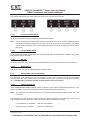
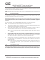
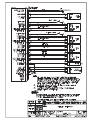
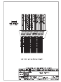
1
SPECIAL NOTICE
This product is now licensed to Anodyne Electronics Manufacturing (AEM) from Northern
Airborne Technology (NAT). AEM is responsible for all matters related to this product, including
sales, support and repair services.
Please note the transition to convert product manuals and supporting documentation is an
ongoing process and is being addressed on an ‘as needed’ basis.
All references to NAT product part numbers (and associated images) are equivalent to AEM
product part numbers.
Contact info:
Anodyne Electronics Manufacturing Corp.
#15-1925 Kirschner Road
Kelowna B.C. Canada
V1Y 4N7
Email: [email protected]
Toll Free: 1-888-763-1088
Phone: 1-250-763-1088
Fax: 1-250-763-1089
www.aem-corp.com
SM09-2
AA83-001
InterMUSIC™ Stereo Intercom System
Serial No. 2938 and below
INSTALLATION AND OPERATION MANUAL
REV 5.00
April 17, 2012
Anodyne Electronics Manufacturing Corp.
15-1925 Kirschner Road
Kelowna, BC, Canada.
V1Y 4N7
Telephone (250) 763-1088
Facsimile (250) 763-1089
Website: www.aem-corp.com
© 2012 Anodyne Electronics Manufacturing Corp. (AEM),
All Rights Reserved
CONFIDENTIAL AND PROPRIETARY TO ANODYNE ELECTRONICS MANUFACTURING CORP.
AA83-001 InterMUSIC™ Stereo Intercom System
SM09-2 Installation and Operation Manual
COPYRIGHT STATEMENT
© 2012 Anodyne Electronics Manufacturing Corp. (AEM), All Rights Reserved
This publication is the property of AEM and is protected by Canadian copyright
laws. No part of this document may be reproduced or transmitted in any form or
by any means including electronic, mechanical, photocopying, recording, or
otherwise, without the prior written permission of AEM.
Installation and Operation Manual
Page ii
ENG-FORM: 820-0100.DOTX
CONFIDENTIAL AND PROPRIETARY TO ANODYNE ELECTRONICS MANUFACTURING CORP.
AA83-001 InterMUSIC™ Stereo Intercom System
SM09-2 Installation and Operation Manual
Prepared By:
Checked By:
Tony Pearson
Designer
Apr 17, 2012
Approved By:
Tom Betzelt
Product Support
Manager
May 28, 2012
Loen Clement
Designer
May 24/12
The status of this installation and operation manual is controlled by issue shown on the title page. The
status of each section is controlled by revision shown in the footer of each page. All revisions affecting
sections of this manual have been incorporated into the latest issue.
AEM MANUAL REVISIONS
Section
Revision Number
Revision Description
Issue Date
All
Rev 5.00
Updated template and drawings
April 17, 2012
Installation and Operation Manual
Page iii
ENG-FORM: 820-0100.DOTX
CONFIDENTIAL AND PROPRIETARY TO ANODYNE ELECTRONICS MANUFACTURING CORP.
AA83-001 InterMUSIC™ Stereo Intercom System
SM09-2 Installation and Operation Manual
Table of Contents
Section
Title
1.0
Description
1.1
1.2
1.3
1.3.1
1.3.2
1.4
1.4.1
1.4.2
1.4.3
Introduction
Purpose of Equipment
Features
Stereo & Intercom Special Features
Communication Functions
Specifications
Electrical Specifications
Physical Specifications
Environmental Specifications
2.0
Installation
2.1
2.2
2.2.1
2.3
2.3.1
2.3.2
2.3.3
2.3.4
2.3.5
2.3.6
2.3.7
2.3.8
2.3.9
2.4
2.5
2.6
Introduction
Unpacking and Inspection
Warranty
Installation Procedures
Warnings
Cautions
Cabling and Wiring
Installation Notes
Adjustments
Setting Music Input Compatibility
Mechanical Installation
Post-Installation Checks
Final Check
Continued Airworthiness
Accessories Required
Installation Drawings
3.0
Operation
3.1
3.2
3.2.1
3.2.2
3.3
3.3.1
3.3.2
3.3.3
3.3.4
3.3.5
3.3.6
3.3.7
Introduction
General
Stereo & Intercom Special Features
Communication Functions
Controls and Indicators
ICS VOL/VOX
MUSIC VOL/COPILOT VOX
Annunciator
VOX Operation
Mode Switch
Automatic Fail-safe
Muting Explanation
Installation and Operation Manual
Page
1-1
1-1
1-1
1-1
1-1
1-2
1-2
1-3
1-3
2-1
2-1
2-1
2-1
2-1
2-1
2-2
2-2
2-2
2-3
2-4
2-4
2-5
2-6
2-6
2-6
3-1
3-1
3-1
3-1
3-2
3-2
3-2
3-2
3-3
3-3
3-4
3-5
Page iv
ENG-FORM: 820-0100.DOTX
CONFIDENTIAL AND PROPRIETARY TO ANODYNE ELECTRONICS MANUFACTURING CORP.
AA83-001 InterMUSIC™ Stereo Intercom System
SM09-2 Installation and Operation Manual
Section 1.0 Description
1.1
Introduction
This manual contains information on the AA83-001 InterMUSIC™. All derivative products will be covered
by manual supplements, which can be obtained from AEM as required. Information in this section
consists of purpose of equipment, features and specifications.
1.2
Purpose of Equipment
The AA83-001 is a 4-place stereo voice-activated intercom, providing full intercom capabilities for pilot, co-pilot
and two passengers (PAX). It provides entertainment and communication audio in full stereo to all four
headsets, and transceiver control for both the pilot and co-pilot. The InterMUSIC™ family of stereo intercoms
allows several installation configurations – from single unit systems, to fully independent stations for the pilot,
co-pilot and passengers. For expanded systems, tie line connections are compatible with other AEM systems
including AA80, AA82, AMS4x and AA9x series units.
1.3
Features
1.3.1
Stereo & Intercom Special Features
The stereo music audio is muted during transmit or intercom operation and when radio receive audio is
detected, permitting greater intelligibility of incoming transmissions.
The AA83-001 muting depth
adjustment ranges from complete music muting to gentle background music on command, with a fast
attack and slow level return for optimum user comfort. Each microphone is individually gated, for the best
possible noise performance during VOX operation. A front panel annunciator allows easy visual setting of
the VOX threshold, and also indicates transmit operation.
1.3.2
Communication Functions
The AA83-001 provides full boom-mic transmit and ICS functions for the pilot and coPilot, and provides ICS and radio monitor operation for two additional passengers. Pilot priority on
transmit and pilot isolation (direct connection to the aircraft radio system) are standard features on all
AEM intercom systems. The AA83-001 can support PTT ICS operation for all users, and can be wired to
cyclic/yoke switches for both TX and ICS functions.
The balance adjustment pots permit signals to be shifted in the user’s acoustic listening space so that
tower transmissions appear to come from one area, and intercom from another. This greatly aids in
signal recognition an more accurately reproduces a natural listening environment for the flight crew.
April 17, 2012 Rev: 5.00
Page 1-1
ENG-FORM: 800-0100.DOTX
CONFIDENTIAL AND PROPRIETARY TO ANODYNE ELECTRONICS MANUFACTURING CORP.
AA83-001 InterMUSIC™ Stereo Intercom System
SM09-2 Installation and Operation Manual
1.4
Specifications
1.4.1
Electrical Specifications
Input Power
+11 to +32 Vdc. Nominal 14/28 Vdc systems
Supply Current
0.4A max. (full output power, all users)
Headset Power:
Typical 100 mW into each side each headset
(300 Ω ear element)
4 headsets total
Total maximum power 400 mW per channel
Indicators:
Transmit (Green LED)
(ICS (Amber LED)
Inputs:
4 Microphone
‘carbon equivalent’
250 mVrms for full output
150 Ω input impedance
2 TX keylines
Active ground, for Pilot & Copilot
4 ICS keylines
Active ground, for all users
2 music inputs
Compatible, left & right
Configurable for either Walkman™/Discman™
phones compatible (3 Vp-p), or Line Output
compatible (100-500 mV @ 10 kΩ)
1 Aircraft radio input
2.5 Vrms for full output
1 kΩ input impedance
1 bi-directional ICS Tie Line
1 Vp-p for full output
2.2 kΩ input impedance
Outputs:
4 aircraft stereo headsets (300 Ω/side)
Not designed for 8 Ω headsets
1 radio microphone output to aircraft audio panel
1 TX keyline output (hard ground for TX)
Logic:
TX, active ICS, and incoming Receive Audio all mute the music
channel (Muting depth adjustable)
Fast attack, slow return of music signal Pilot TX priority
April 17, 2012 Rev: 5.00
Page 1-2
ENG-FORM: 800-0100.DOTX
CONFIDENTIAL AND PROPRIETARY TO ANODYNE ELECTRONICS MANUFACTURING CORP.
AA83-001 InterMUSIC™ Stereo Intercom System
SM09-2 Installation and Operation Manual
1.4.2
Physical Specifications
Dimensions excluding front panel:
1.4.3
Height
1.30” (33.0 mm) max.
Depth
5.60” (142.2 mm) max
Width
2.60” (66.0 mm) max
Weight
0.60 lbs (283.5g) excluding external hardware
Mounting
Horizontal or vertical through-panel mounting
Environmental Specifications
Temperature:
Operating
Storage
-40˚C. to +70˚C
-55˚C to +85˚C
Altitude
25,000 feet
Humidity
95% Non-condensing
Shock
DO-160C category “P”, panel mounting 6 G.
End of Section 1.0
April 17, 2012 Rev: 5.00
Page 1-3
ENG-FORM: 800-0100.DOTX
CONFIDENTIAL AND PROPRIETARY TO ANODYNE ELECTRONICS MANUFACTURING CORP.
AA83-001 InterMUSIC™ Stereo Intercom System
SM09-2 Installation and Operation Manual
Section 2.0 Installation
2.1
Introduction
Information in this section consists of: unpacking and inspection procedures, installation procedures,
post-installation checks, and installation drawings.
2.2
Unpacking and Inspection
Unpack the equipment carefully. Inspect the unit visually for damage due to shipping and report all such
claims immediately to the carrier involved. Note that each unit should have the following:
-
AA83-001 InterMUSIC™
Product Information Card
Release certification
Installation kit (Section 2.5)
Verify that all items are present before proceeding and report any shortage immediately to your supplier.
2.2.1
Warranty
All Anodyne Electronics Manufacturing Corp. (AEM) products are warranted for 2 years. See the website
www.aem-corp.com/warranty for complete details.
2.3
Installation Procedures
2.3.1
Warnings
Do not bundle any lines from this unit with transmitter coax lines. Do not bundle any logic, audio, or DC
power lines from this unit with 400 Hz synchro wiring or AC power lines. Do not position this unit next to
any device with a strong alternating magnetic field such as an inverter, motor or blower, or significant
audio interference will result.
2.3.2
Cautions
In all installations, use shielded cable exactly as shown and ground as indicated. Significant problems
may result from not following these guidelines.
All audio installations can be seriously degraded by incorrect wiring and shielding, and may result in
abnormal cross-talk, hum and ground-loop noise. Be especially careful with all microphone wiring and
Tie Line wiring, as these lines carry the lowest level signals in the aircraft.
All microphone and headset jacks should be electrically isolated from the airframe or significant ground
loop noise may result.
April 17, 2012 Rev: 5.00
Page 2-1
ENG-FORM: 805-0100.DOTX
CONFIDENTIAL AND PROPRIETARY TO ANODYNE ELECTRONICS MANUFACTURING CORP.
AA83-001 InterMUSIC™ Stereo Intercom System
SM09-2 Installation and Operation Manual
2.3.3
Cabling and Wiring
All unshielded wire should be to MIL-W-22759 or equivalent. For shielded wire applications, use Tefzel
MIL-C-27500 shielded wire with solder sleeves (for shield terminations) to make the most compact and
easily terminated interconnect. Follow the wiring diagrams in Section 2.6 as required.
Allow 3 inches from the end of the wire to the shield termination to allow the hood to be easily installed.
Note that the hood is a ‘clamshell’ hood, and is installed after the wiring is complete. Aircraft harnessing
should permit the unit to be lowered from the panel for easy access to all side adjustments. Do NOT
mount the unit until all adjustments have been carried out.
All wiring should be at least 22 AWG, except power and ground lines, which should be at least 20 AWG.
Ensure that the ground connection is clean and well secured, and that it shares no path with any
electrically noisy aircraft accessories such as blowers, turn and bank instruments or similar loads. Power
to this unit must be supplied from a separate breaker (1/2 A) or fuse (1/2 A fast), and not attached to any
other existing breaker without additional protection. The correct fuse is included with the AA83-001.
2.3.4
Installation Notes
All AA95/AMS4X Audio Controllers used with the AA83-001 must have the ICS Tie Line and Gain
Modifications installed. This will only be a concern on Audio Controllers with S/N 1918 or before. If the
AA83-001 is used with a second unit such as an AA82, you may wish to install the 2.2 k: resistor shown
in the installation drawing. This is used to equalize ICS Tie Line loading when changing from the tie to
split connections.
If you are not familiar with Tie Line techniques, request the installation bulletin from AEM covering Tie
Line theory and practice.
2.3.5
Adjustments
The unit ships from the factory with all internal adjustments set to the normal test levels. Once installed in
the aircraft, it may be desirable to change some of these settings to best suit the local operating
environment.
CAUTION
Before performing the following adjustments ensure the aircraft radio’s volume
control is set to produce 2.5 Vrms r10 % at the input to the AA83-001, or the mute
functions may not operate correctly.
April 17, 2012 Rev: 5.00
Page 2-2
ENG-FORM: 805-0100.DOTX
CONFIDENTIAL AND PROPRIETARY TO ANODYNE ELECTRONICS MANUFACTURING CORP.
AA83-001 InterMUSIC™ Stereo Intercom System
SM09-2 Installation and Operation Manual
The internal adjustments are located along the sides of the unit and are as follows:
2.3.5.1
ICS, RX, and MUSIC BAL
These potentiometers are used to adjust the headset stereo balance.
Note:
2.3.5.2
The balance adjustment pots permit signals to be shifted in the user's acoustic listening space so
that tower transmissions appear to come from one area, and intercom from another. This greatly
aids in signal recognition and more accurately reproduces a natural listening environment for the
flight crew.
ICS and MUSIC BASS
These potentiometers are used to adjust the amount of bass audio to the headsets. Rotating ccw will lower
the bass level, and cw will raise it.
2.3.5.3
RX VOL
To reduce the receive audio volume, rotate this potentiometer ccw, and to increase the volume, rotate it cw.
2.3.5.4
MUSIC MUTE
The music mute level can be adjusted using this potentiometer.
2.3.6
Setting Music Input Compatibility
The AA83-001 (S/N 1091and up) can be configured to be Low-Z or High-Z circuits by two internal
jumpers (J103 and J104), which can be accessed by removing the cover and top PCB from the AA83001. The AA83-001 is normally shipped from the factory as a Low-Z version.
2.3.6.1
Jumper Adjustment
Refer to Component Locator AA83\001\924-0 in Section 6 of the AA83-001 Maintenance Manual. If any
further information is required, contact the Product Support department at AEM Corp.
Note:
The AA83-001 is a static sensitive device. Use proper ESD handling procedures when the cover
is removed.
The two types of music inputs are configured by the position of jumpers J103 and J104, located on the
main PCB near the access hole for Q101. Music input type is determined as follows:
Low Z/Walkman™ compatible
J103 and J104 Installed
High Z/Pre-Amp compatible
J103 and J104 Removed
April 17, 2012 Rev: 5.00
Page 2-3
ENG-FORM: 805-0100.DOTX
CONFIDENTIAL AND PROPRIETARY TO ANODYNE ELECTRONICS MANUFACTURING CORP.
AA83-001 InterMUSIC™ Stereo Intercom System
SM09-2 Installation and Operation Manual
To gain access to the jumpers, remove the cover from the AA83-001. Remove the top PCB by removing
three pan-head screws and carefully lifting it straight up.
When reassembling the unit ensure the pins and connector are aligned properly before screwing the PCB
down.
2.3.7
Mechanical Installation
The AA83-001 can be installed in a vertical or horizontal attitude directly on the instrument console, using
the AA83-IKC Installation kit (see Section 2.5 for details).
Before the unit is mounted, make all functional tests and trimpot adjustments. Be sure the harness has
enough clearance to permit the unit to be dropped down for re-adjustment, if needed later. Make sure
unit is securely fastened to the panel, and that the connector locks are tightened before any flight is
attempted.
For proper installation, refer to the Drill Template (AA83\001\921-0) and the following steps:
Note: The mounting nuts on the panel pots should not be removed at any time.
a)
After deciding the attitude (vertical or horizontal) of the unit, drill the required mounting holes in the
aircraft panel and insert the AA83-001 from behind the panel.
b)
Remove the protective plastic film from the black metal faceplate, and position it with the
appropriate legend orientation facing out. Secure with the mounting screws provided.
Note:
Ensure that the aircraft panel is tightly ‘sandwiched’ between the AA83-001 and the
faceplate.
c)
Rotate the inner and outer shafts of the ICS VOL / VOX potentiometer fully ccw. The outer knob
may be rotated by hand, but it may be necessary to temporarily attach the inner ICS knob to
facilitate this action. Align the white markers on the knobs to the LIVE position on the faceplate
label. Using a 0.05" Allen key, tighten the knobs onto the potentiometer shafts.
d)
Rotate the shaft of the MUSIC VOL potentiometer fully ccw. Align the white marker on the knob
to the MIN position on the faceplate label. Using a 0.05" Allen key, tighten the knob onto the
potentiometer shaft.
Note:
2.3.8
Make sure there is enough clearance between the concentric knobs so that rotating one
does not also move the other. A piece of paper makes a good spacer when setting up
the clearance.
Post-Installation Checks
If any preset requires adjustment, be sure this is carried out before the aircraft leaves, and that the unit
and its mating connector are secured before departure. Make all required log book entries, electrical
load, weight and balance amendments and other paperwork as required by your local regulatory agency.
April 17, 2012 Rev: 5.00
Page 2-4
ENG-FORM: 805-0100.DOTX
CONFIDENTIAL AND PROPRIETARY TO ANODYNE ELECTRONICS MANUFACTURING CORP.
AA83-001 InterMUSIC™ Stereo Intercom System
SM09-2 Installation and Operation Manual
2.3.8.1
Voltage/resistance checks
Do not attach the AA83-001 until the following conditions are met.
Check the following:
a)
Check P101, pin <1> for +9 to +32 Vdc relative to ground.
b)
Check P101, pin <16> for continuity to ground (less than 0.5 :).
c)
Check P101, pins <11> and <12> for continuity to ground (less than 0.5 :) when the relevant ICS
switch is keyed.
d)
Check all mic, phone, music, and key lines for shorts to ground or adjacent pins. Check all key
lines for correct operation.
2.3.8.2
Power On checks
Install the AA83-001 and power up the aircraft’s systems, and turn on the radios and accessories
required. Verify normal operation of all functions. Refer to Section 3 for specific operation details.
a)
Begin with only the pilot's headset installed, no hand mic. Check for correct radio operation (both
receive and transmit) and ICS operation. Check yoke (or cyclic) switch action.
b)
If there is a music source in the system turn it on and verify that music is heard in all modes
except PLT ISO. Check for proper mute operation.
Note:
Unusual buzzes, hums or other background audio may be symptomatic of multiple grounds or
noisy external systems sharing the same wire bundle. Incorrect jack wiring is a common fault,
especially for passenger stations, and may cause loss of audio, a tone on the headset lines, or
other problems.
c)
Plug in the copilot's headset. Check for correct radio and ICS operation. Check pilot's transmit
priority. Check yoke or cyclic switch functions, if applicable.
d)
Plug in the hand mic (if applicable to the installation), and test for correct operation in all modes.
It must activate the transmitter(s) in all cases.
e)
Plug in any remaining headsets, and check for correct ICS operation.
f)
To verify proper operation, all functions and levels should be checked in-flight.
Be sure headsets are of good quality and are installed correctly. Unless the AA83-001 has specifically
been wired for mono operation NEVER USE MONO AIRCRAFT HEADSETS in the system, as they will
short out one side of the AA83-001 power amplifier when installed in stereo jacks. This may result in
eventual unit failure, which IS NOT COVERED BY WARRANTY.
2.3.9
Final Check
Fly the aircraft and check levels and operation of all functions. You may wish to change Bass or Balance
controls after flight, depending on how the system performs with regard to ambient noise.
Upon satisfactory completion of all performance checks, make the required log entries and
complete the necessary Regulatory Agency paperwork before releasing the aircraft for service.
April 17, 2012 Rev: 5.00
Page 2-5
ENG-FORM: 805-0100.DOTX
CONFIDENTIAL AND PROPRIETARY TO ANODYNE ELECTRONICS MANUFACTURING CORP.
AA83-001 InterMUSIC™ Stereo Intercom System
SM09-2 Installation and Operation Manual
2.4
Continued Airworthiness
Maintenance of the AA83-001 is ‘on condition’ only. Periodic maintenance of this product is not required.
2.5
Accessories Required
Installation kit p/n AA83-IKC is required to complete the installation. The kit consists of the following:
Quantity
1
1
3
1
1
1
1
Description
AEM Part #
D-min 44 Pin Female Crimp Installation Kit
AGC 1/2A Fuse
5/8” 6-32 Black Pan Head Screw
Fluted 1/8” ICS Knob
Fluted 1/8” Music Knob
Hole Overlay
Rectangular Faceplate
D44SL-IKC
23-00-005
25-11-427
40-21-ICS3
40-21-MUS3
43-10-083
50-04-831
The AEM Part #: D44SL-IKC consists of:
Quantity
Description
1
D-min 44 Socket Housing
44
Mini D Crimp Socket
1*
Jack Screw Set
1*
Lock Clip Set
1
25 pin Connector Hood
* Use as required.
2.6
AEM Part #
20-20-044
20-26-703
20-27-002
20-27-004
20-29-026
Installation Drawings
DRAWING
REV.
DESCRIPTION
AA83\001\302-0
AA83\001\403-0
AA83\001\405-0
AA83\001\921-0
1.00
2.00
2.00
1.00
InterMUSIC System
InterMUSIC Stereo Intercom
InterMUSIC Stereo Intercom
Drill Template
TYPE
Block Diagram
Interconnect
Connector Map
Mounting Plate
Section 2.0 ends following the above documents
April 17, 2012 Rev: 5.00
Page 2-6
ENG-FORM: 805-0100.DOTX
CONFIDENTIAL AND PROPRIETARY TO ANODYNE ELECTRONICS MANUFACTURING CORP.
Confidential and Proprietary to NAT
Confidential and Proprietary to NAT
AA83-001 InterMUSIC™ Stereo Intercom System
SM09-2 Installation and Operation Manual
Section 3.0 Operation
3.1
Introduction
Information in this section consists of the functional and operational procedures for the AA83-001
InterMUSIC™ stereo intercom.
3.2
General
The AA83-001 InterMUSIC™ is a stereo intercom system that supports a pilot, copilot and two
passengers. It provides entertainment and communication audio in full stereo to all four headsets, and
transceiver control for both the pilot and copilot. The InterMUSIC™ family of stereo intercoms allows
several installation configurations from single unit systems, to fully independent stations for the pilot,
copilot and passengers. Tie Line connections are compatible with other AEM systems including AA82,
AMS40 and AA95 series units for expanded systems.
3.2.1
Stereo & Intercom Special Features
The stereo music audio is muted during transmit or intercom operation and when radio receive audio is
detected, permitting greater intelligibility of incoming transmissions. The AA83-001 muting depth
adjustment ranges from complete music muting to gentle background music on command, with a fast
attack and slow level return for optimum user comfort. Each microphone is individually gated, for the best
possible noise performance during VOX operation. A front panel annunciator allows easy visual setting of
the VOX threshold, and also indicates transmit operation.
3.2.2
Communication Functions
The AA83-001 provides full boom-mic transmit and ICS functions for the pilot and co-pilot, and provides
ICS and radio monitor operation for two additional passengers. Pilot priority on transmit and pilot isolation
(direct connection to the aircraft radio system) are standard features on all AEM intercom systems. The
AA83-001 can support PTT ICS operation for all users, and can be wired to cyclic/yoke switches for both
TX and ICS functions.
The balance adjustment pots permit signals to be shifted in the user's acoustic listening space so that
tower transmissions appear to come from one area, and intercom from another. This greatly aids in
signal recognition and more accurately reproduces a natural listening environment for the flight crew.
April 17, 2012 Rev: 5.00
Page 3-1
ENG-FORM: 806-0100.DOTX
CONFIDENTIAL AND PROPRIETARY TO ANODYNE ELECTRONICS MANUFACTURING CORP.
AA83-001 InterMUSIC™ Stereo Intercom System
SM09-2 Installation and Operation Manual
3.3
Controls and Indicators
ICS VOL (Inner)
PILOT VOX (Outer)
Mode Switch
3.3.1
MUSIC VOL (Inner)
COPILOT VOX
(Outer)
Annunciator
ICS VOL/VOX
The ICS VOL/PILOT VOX control is a fluted concentric rubber knob on the left side of the front panel.
The inner (front) knob is the ICS VOL control, which is used to set Intercom volume. It is at minimum volume
when fully counter-clockwise (ccw). As the knob is rotated clockwise (cw), the ICS volume for crew and
PAX increases. The ICS is muted during transmit operations.
The outer (rear) knob is the PILOT VOX control. For full information on VOX operation, see section 3.3.4.
3.3.2
MUSIC VOL/COPILOT VOX
The MUSIC VOL control is a fluted concentric rubber knob on the right side of the front panel.
The inner (front) knob is the MUSIC VOL control, which is used to set normal music volume. The volume is
at minimum when fully counter-clockwise (ccw), and as the knob is rotated clockwise (cw), the volume
increases. Music is muted during transmit operations.
The outer (rear) knob is the COPILOT VOX control. For full information on VOX operation, see section
3.3.4.
3.3.3
Annunciator
The front panel annunciator is a bi-colour LED that shows intercom status.
If the LED is illuminated green, it indicates transmit activity, and if it is red, it indicates VOX activity. For
transmit with sidetone or mic activity, it will illuminate amber. The green LED also indicates a possible
stuck mic if still lit after transmission is concluded.
April 17, 2012 Rev: 5.00
Page 3-2
ENG-FORM: 806-0100.DOTX
CONFIDENTIAL AND PROPRIETARY TO ANODYNE ELECTRONICS MANUFACTURING CORP.
AA83-001 InterMUSIC™ Stereo Intercom System
SM09-2 Installation and Operation Manual
3.3.4
VOX Operation
The VOX control is used to set the level of audio required to activate the microphones.
The AA83-001 provides three modes of intercom operation, selected by the position of the VOX control.
LIVE ICS
When the VOX control is positioned fully ccw, the relevant mics will be live, and any
sound picked up will be processed by the ICS system (hot mic).
KEYED ICS
When the VOX control is positioned fully cw to the MAX position, the intercom will be in a
keyed-only mode.
VOX ICS
When the VOX control is positioned between fully cw and fully ccw, the intercom is in
VOX mode. To establish the VOX threshold, rotate the control ccw until the LED turns
red, and then rotate the control cw until the LED goes dark. Continue turning the control
cw until the desired voice sensitivity is set.
3.3.5
Mode Switch
The Mode switch is a red three-position toggle switch that is used to select the operational mode of the
AA83-001.
3.3.5.1
Normal Mode
In normal use, the AA83-001 serves as a common intercommunication system for up to four users, and a
flow-through interface for connection to the ship's external communication system. The front panel
controls allow both the pilot and copilot (plus the passengers) to set their respective VOX trigger points
independently to match different headsets or noise locations.
For normal operation, the MODE switch is set to the NORMAL (down) position. A transmit command
from either the pilot or copilot will send their microphone signal through to the aircraft communication
system. Correct operation will be indicated by the front panel indicator lighting green.
3.3.5.2
Pilot Isolation Operation
In normal operation, the pilot, copilot, and passengers hear the same signals from the aircraft
communication system. Sometimes this is not desirable from the pilot's perspective, such as when he
needs to communicate with the tower on approach or has a heavy traffic load, and is not interested in the
discussions on the intercom.
The MODE switch has a middle position, marked PILOT ISO, which disconnects the pilot from the internal
amplifier of the AA83-001 and connects the pilot directly to the aircraft communication system. All other
users are unaffected and continue to use the entertainment and intercom functions of the AA83-001. The
pilot has no ICS or music operation when selected to PIL ISO, and all his signals are presented in mono
format during this mode.
This mode is 'fail-passive', meaning that it requires no power to operate and is the same mode the box
goes into automatically when power is lost to the AA83-001. In this way, switch over is immediate for
the pilot and there is no possibility of lost communication because of a lack of pilot action. Note that the
pilot's boom mic is sent directly to the radio in this mode, and only a PTT key input is needed to transmit.
April 17, 2012 Rev: 5.00
Page 3-3
ENG-FORM: 806-0100.DOTX
CONFIDENTIAL AND PROPRIETARY TO ANODYNE ELECTRONICS MANUFACTURING CORP.
AA83-001 InterMUSIC™ Stereo Intercom System
SM09-2 Installation and Operation Manual
3.3.5.3
Tie/Split Operation
The MODE switch has one further position, which can be used in expanded systems for more complex
audio circuits. If an outboard AA82 has been installed (or some other AEM system with tie line
capability), then this switch will open and close the tie line output to create common or split intercom
circuits with the external system.
In all positions other than SPLIT, the ICS tie line is sent to outside systems for common intercom
operation. This can be used for common communication from front to rear (for example) in a larger
aircraft. When set to the SPLIT position, the AA83-001 cuts the tie line, breaking the two units into
individual intercom circuits with isolated conversations. In this way, many different circuit combinations
can be set up, depending on what device is hooked to the tie line.
With no external unit, the SPLIT position has no function within the AA83-001.
3.3.6
Automatic Fail-safe
In the event of a power failure, automatic fail-safe operation will be activated. This routes the pilot’s
phones, mic audio, and mic PTT directly to the COM radio. Copilot and passengers will have no ICS,
music, or receive functions.
The pilot mic is directly connected to the transceiver mic. Mic bias is provided by the transceiver, not the
AA83-001. The pilot TX keyline is directly connected to the transceiver.
During receive mode, receive audio is directly connected from the audio source to the pilot phones, and
during transmit mode, the sidetone audio is directly connected from the audio source to the pilot phones.
In both cases, copilot and passengers have no ICS, music, sidetone, or receive functions.
In the unlikely event of an AA83-001 circuit failure that results in a communication problem, the automatic
fail-safe mode can be enabled by pulling the AA83-001 circuit breaker.
Note:
In Automatic Fail-Safe mode, the receive/sidetone levels may require adjustment at the audio
source.
The pilot should confirm that all aspects of Automatic Fail-Safe operation are working before
accepting the aircraft into service.
April 17, 2012 Rev: 5.00
Page 3-4
ENG-FORM: 806-0100.DOTX
CONFIDENTIAL AND PROPRIETARY TO ANODYNE ELECTRONICS MANUFACTURING CORP.
AA83-001 InterMUSIC™ Stereo Intercom System
SM09-2 Installation and Operation Manual
3.3.7
Muting Explanation
When transmitting, any music will be muted quickly, and will slowly return when transmission is
completed. Music will also be muted when ICS or RX functions are active. The degree of muting is set
via the MUSIC MUTE adjustment explained in the installation section of this manual. The relative volume
of the music can be changed from the front panel by the knob marked with a musical note.
Below is a simple chart to aid in understanding audio switching in the NORMAL Operation mode. The
following terms are used:
' Active' - Function being used.
' Muted' - Functions that are overridden by the active condition.
' Idle'
- Functions that are not active, but still available for use.
Music
ICS
Active
Muted
Muted
Muted
Muted
Idle
Active
Idle
Muted
Muted
RX
Pilot TX
Copilot TX
Idle
Idle
Active
Idle
Idle
Idle
Idle
Idle
Active
Idle
Idle
Idle
Idle
Muted
Active
End of Section 3.0
April 17, 2012 Rev: 5.00
Page 3-5
ENG-FORM: 806-0100.DOTX
CONFIDENTIAL AND PROPRIETARY TO ANODYNE ELECTRONICS MANUFACTURING CORP.