1
Management
Software
Layer 2-4 Gigabit
Ethernet EcoSwitches
AT-9000/28
AT-9000/28SP
AT-9000/52
◆
Command Line
User’s Guide
AlliedWare Plus Version 2.1.1
613-001311 Rev A
Copyright
Copyright © 2010, Allied Telesis, Inc.
All rights reserved.
This product includes software licensed under the BSD License. As such, the following language applies for those portions of
the software licensed under the BSD License:
Redistribution and use in source and binary forms, with or without modification, are permitted provided that the following
conditions are met:
* Redistributions of source code must retain the above copyright notice, this list of conditions and the following disclaimer.
* Redistributions in binary form must reproduce the above copyright notice, this list of conditions and the following
disclaimer in the documentation and/or other materials provided with the distribution.
* Neither the name of Allied Telesis, Inc. nor the names of the respective companies above may be used to endorse or promote
products derived from this software without specific prior written permission.
THIS SOFTWARE IS PROVIDED BY THE COPYRIGHT HOLDERS AND CONTRIBUTORS "AS IS" AND ANY
EXPRESS OR IMPLIED WARRANTIES, INCLUDING, BUT NOT LIMITED TO, THE IMPLIED WARRANTIES OF
MERCHANTABILITY AND FITNESS FOR A PARTICULAR PURPOSE ARE DISCLAIMED. IN NO EVENT SHALL
THE COPYRIGHT HOLDER OR CONTRIBUTORS BE LIABLE FOR ANY DIRECT, INDIRECT, INCIDENTAL,
SPECIAL, EXEMPLARY, OR CONSEQUENTIAL DAMAGES (INCLUDING, BUT NOT LIMITED TO,
PROCUREMENT OF SUBSTITUTE GOODS OR SERVICES; LOSS OF USE, DATA, OR PROFITS; OR BUSINESS
INTERRUPTION) HOWEVER CAUSED AND ON ANY THEORY OF LIABILITY, WHETHER IN CONTRACT,
STRICT LIABILITY, OR TORT (INCLUDING NEGLIGENCE OR OTHERWISE) ARISING IN ANY WAY OUT OF THE
USE OF THIS SOFTWARE, EVEN IF ADVISED OF THE POSSIBILITY OF SUCH DAMAGE.
Copyright 1989, 1991, 1992 by Carnegie Mellon University. Derivative Work - 1996, 1998-2000. Copyright 1996, 1998-2000
by The Regents of the University of California - All rights reserved. Copyright (c) 2001-2003 by Networks Associates
Technology, Inc. - All rights reserved. Copyright (c) 2001-2003 by Cambridge Broadband Ltd. - All rights reserved. Copyright
(c) 2003 by Sun Microsystems, Inc. - All rights reserved. Copyright (c) 2003-2005 by Sparta, Inc. - All rights reserved.
Copyright (c) 2004 by Cisco, Inc. and Information Network Center of Beijing University of Posts and Telecommunications. All rights reserved. Copyright (c) 2003 by Fabasoft R&D Software GmbH & Co KG - All rights reserved. Copyright (c) 20042006 by Internet Systems Consortium, Inc. ("ISC") - All rights reserved. Copyright (c) 1995-2003 by Internet Software
Consortium - All rights reserved. Copyright (c) 1992-2003 by David Mills - All rights reserved. Copyright (c) 1995 by Tatu
Ylonen <[email protected]>, Espoo, Finland - All rights reserved. Copyright (c) 1998 by CORE SDI S.A., Buenos Aires,
Argentina - All rights reserved. Copyright 1995, 1996 by David Mazieres - All rights reserved. Copyright 1983, 1990, 1992,
1993, 1995 by The Regents of the University of California - All rights reserved. Copyright (c) 1995 Patrick Powell - All rights
reserved. Copyright (c) 1998-2005 The OpenSSL Project - All rights reserved. Copyright (C) 1995-1998 Eric Young
([email protected]) - All rights reserved. Copyright (c) 2008, Henry Kwok - All rights reserved. Copyright (c) 1995, 1998,
1999, 2000, 2001 by Jef Poskanzer <[email protected]>. - All rights reserved.
Some components of the SSH software are provided under a standard 2-term BSD license with the following names as
copyright holders: Markus Friedl, Theo de Raadt, Niels Provos, Dug Song, Aaron Campbell, Damien Miller, Kevin Steves,
Daniel Kouril, Wesley Griffin, Per Allansson, Nils Nordman, and Simon Wilkinson,
Portable OpenSSH includes code from the following copyright holders, also under the 2-term BSD license: Ben Lindstrom,
Tim Rice, Andre Lucas, Chris Adams, Corinna Vinschen, Cray Inc., Denis Parker, Gert Doering, Jakob Schlyter, Jason
Downs, Juha Yrjola, Michael Stone, Network Associates, Solar Designer, Todd C. Miller, Wayne Schroeder, William Jones,
Darren Tucker, Sun Microsystems, The SCO Group.
Some Portable OpenSSH code is licensed under a 3-term BSD style license to the following copyright holders: Todd C. Miller,
Theo de Raadt, Damien Miller, Eric P. Allman, The Regents of the University of California, and Constantin S. Svintsoff. Some
Portable OpenSSH code is licensed under an ISC-style license to the following copyright holders: Internet Software
Consortium, Todd C. Miller, Reyk Floeter, and Chad Mynhier. Some Portable OpenSSH code is licensed under a MIT-style
license to the following copyright holder: Free Software Foundation, Inc.
This product also includes software licensed under the GNU General Public License available from:
http://www.gnu.org/licenses/gpl2.html
Allied Telesis is committed to meeting the requirements of the open source licenses including the GNU General Public
License (GPL) and will make all required source code available.
If you would like a copy of the GPL source code contained in this product, please send us a request by registered mail
including a check for US$15 to cover production and shipping costs, and a CD with the GPL code will be mailed to you.
GPL Code Request
Allied Telesis, Inc.
3200 North First Street
San Jose, California 95134
No part of this publication may be reproduced without prior written permission from Allied Telesis, Inc.
Allied Telesis, AlliedWare Plus, and the Allied Telesis logo are trademarks of Allied Telesis, Incorporated. Microsoft and
Internet Explorer are registered trademarks of Microsoft Corporation. All other product names, company names, logos or
other designations mentioned herein are trademarks or registered trademarks of their respective owners.
Allied Telesis, Inc. reserves the right to make changes in specifications and other information contained in this document
without prior written notice. The information provided herein is subject to change without notice. In no event shall Allied
Telesis, Inc. be liable for any incidental, special, indirect, or consequential damages whatsoever, including but not limited
to lost profits, arising out of or related to this manual or the information contained herein, even if Allied Telesis, Inc. has
been advised of, known, or should have known, the possibility of such damages.
Contents
Preface ........................................................................................................................ 29
Document Conventions .................................................................................................................................... 30
Where to Find Web-based Guides ................................................................................................................... 31
Contacting Allied Telesis .................................................................................................................................. 32
Online Support ........................................................................................................................................... 32
Email and Telephone Support.................................................................................................................... 32
Returning Products .................................................................................................................................... 32
Sales or Corporate Information .................................................................................................................. 32
Management Software Updates................................................................................................................. 32
Section I: Getting Started ......................................................................................... 33
Chapter 1: AlliedWare Plus™ Command Line Interface ............................................................................ 35
Management Sessions ..................................................................................................................................... 36
Local Management..................................................................................................................................... 36
Remote Management................................................................................................................................. 36
Management Interfaces.................................................................................................................................... 38
Local Manager Account.................................................................................................................................... 39
AlliedWare Plus™ Command Modes ............................................................................................................... 40
Moving Down the Hierarchy ............................................................................................................................. 43
ENABLE Command ................................................................................................................................... 43
CONFIGURE TERMINAL Command......................................................................................................... 43
CLASS-MAP Command............................................................................................................................. 43
LINE CONSOLE 0 Command .................................................................................................................... 44
LINE VTY Command.................................................................................................................................. 44
POLICY-MAP Command ........................................................................................................................... 44
CLASS Command...................................................................................................................................... 45
INTERFACE PORT Command .................................................................................................................. 45
VLAN DATABASE Command .................................................................................................................... 46
INTERFACE VLAN Command................................................................................................................... 46
INTERFACE TRUNK Command................................................................................................................ 46
LOCATION CIVIC-LOCATION Command ................................................................................................. 47
LOCATION COORD-LOCATION Command ............................................................................................. 47
Moving Up the Hierarchy .................................................................................................................................. 48
EXIT and QUIT Commands ....................................................................................................................... 48
END Command .......................................................................................................................................... 48
DISABLE Command .................................................................................................................................. 49
Port Numbers in Commands ............................................................................................................................ 50
Combo Ports 25 to 28....................................................................................................................................... 51
Command Format............................................................................................................................................. 52
Command Line Interface Features............................................................................................................. 52
Command Formatting Conventions ........................................................................................................... 52
Command Examples.................................................................................................................................. 52
Startup Messages............................................................................................................................................. 53
5
Contents
Chapter 2: Starting a Management Session ................................................................................................ 55
Starting a Local Management Session ............................................................................................................. 56
Starting a Remote Telnet or SSH Management Session.................................................................................. 58
VTY Lines ................................................................................................................................................... 58
What to Configure First ..................................................................................................................................... 60
Creating a Boot Configuration File ............................................................................................................. 60
Changing the Login Passwords.................................................................................................................. 61
Assigning a Name to the Switch................................................................................................................. 61
Adding a Management IP Address............................................................................................................. 62
Saving Your Changes................................................................................................................................. 64
Ending a Management Session ........................................................................................................................ 65
Chapter 3: Basic Command Line Management ........................................................................................... 67
Clearing the Screen .......................................................................................................................................... 68
Displaying the On-line Help .............................................................................................................................. 69
Saving Your Configuration Changes................................................................................................................. 71
Ending a Management Session ........................................................................................................................ 72
Chapter 4: Basic Command Line Management Commands ...................................................................... 73
? (Question Mark Key) ...................................................................................................................................... 75
CLEAR SCREEN .............................................................................................................................................. 77
CONFIGURE TERMINAL ................................................................................................................................. 78
COPY RUNNING-CONFIG STARTUP-CONFIG ..............................................................................................79
DISABLE ........................................................................................................................................................... 80
DO..................................................................................................................................................................... 81
ENABLE ............................................................................................................................................................ 82
END .................................................................................................................................................................. 83
EXIT .................................................................................................................................................................. 84
LENGTH ........................................................................................................................................................... 85
LOGOUT ........................................................................................................................................................... 87
QUIT ................................................................................................................................................................. 88
TERMINAL LENGTH ........................................................................................................................................ 89
WRITE .............................................................................................................................................................. 90
Section II: Basic Operations .....................................................................................91
Chapter 5: Basic Switch Management ......................................................................................................... 93
Adding a Name to the Switch............................................................................................................................ 94
Adding Contact and Location Information ......................................................................................................... 95
Displaying Parameter Settings.......................................................................................................................... 96
Manually Setting the Date and Time ................................................................................................................. 97
Pinging Network Devices .................................................................................................................................. 98
Resetting the Switch ......................................................................................................................................... 99
Restoring the Default Settings to the Switch...................................................................................................100
Setting the Baud Rate of the Console Port .....................................................................................................102
Configuring the Management Session Timers ................................................................................................103
Setting the Maximum Number of Manager Sessions......................................................................................104
Configuring the Banners .................................................................................................................................105
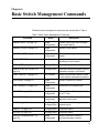
Chapter 6: Basic Switch Management Commands ...................................................................................107
BANNER EXEC ..............................................................................................................................................109
BANNER LOGIN .............................................................................................................................................110
BANNER MOTD .............................................................................................................................................111
BAUD-RATE SET ...........................................................................................................................................112
CLOCK SET....................................................................................................................................................113
6
AT-9000 Switch Command Line User’s Guide
ERASE STARTUP-CONFIG .......................................................................................................................... 114
EXEC-TIMEOUT ............................................................................................................................................ 115
HOSTNAME ................................................................................................................................................... 117
LINE CONSOLE ............................................................................................................................................. 118
LINE VTY........................................................................................................................................................ 119
NO HOSTNAME............................................................................................................................................. 120
PING............................................................................................................................................................... 121
REBOOT ........................................................................................................................................................ 122
RELOAD......................................................................................................................................................... 123
SERVICE MAXMANAGER............................................................................................................................. 124
SHOW BAUD-RATE....................................................................................................................................... 125
SHOW CLOCK ............................................................................................................................................... 126
SHOW RUNNING-CONFIG ........................................................................................................................... 127
SHOW SWITCH ............................................................................................................................................. 128
SHOW SYSTEM............................................................................................................................................. 130
SHOW USERS ............................................................................................................................................... 131
SNMP-SERVER CONTACT........................................................................................................................... 133
SNMP-SERVER LOCATION.......................................................................................................................... 134
Chapter 7: Port Parameters ........................................................................................................................ 135
Adding Descriptions........................................................................................................................................ 136
Setting the Speed and Duplex Mode.............................................................................................................. 137
Setting the MDI/MDI-X Wiring Configuration .................................................................................................. 139
Enabling or Disabling Ports ............................................................................................................................ 140
Enabling or Disabling Backpressure............................................................................................................... 141
Enabling or Disabling Flow Control ................................................................................................................ 142
Resetting Ports ............................................................................................................................................... 145
Configuring Threshold Limits for Ingress Packets .......................................................................................... 146
Blocking Broadcast, Multicast or Unknown Unicast Packets.......................................................................... 148
Reinitializing Auto-Negotiation........................................................................................................................ 150
Restoring the Default Settings........................................................................................................................ 151
Displaying Port Settings ................................................................................................................................. 152
Displaying or Clearing Port Statistics ............................................................................................................. 154
Chapter 8: Port Parameter Commands ..................................................................................................... 155
BACKPRESSURE .......................................................................................................................................... 157
BPLIMIT.......................................................................................................................................................... 159
CLEAR PORT COUNTER.............................................................................................................................. 160
DESCRIPTION ............................................................................................................................................... 161
DUPLEX ......................................................................................................................................................... 162
EGRESS-RATE-LIMIT ................................................................................................................................... 163
FCTRLLIMIT................................................................................................................................................... 164
FILTERING..................................................................................................................................................... 165
FLOWCONTROL............................................................................................................................................ 167
HOLBPLIMIT .................................................................................................................................................. 170
LINKTRAP ...................................................................................................................................................... 172
NO EGRESS-RATE-LIMIT ............................................................................................................................. 173
NO FILTERING .............................................................................................................................................. 174
NO FLOWCONTROL ..................................................................................................................................... 176
NO LINKTRAP................................................................................................................................................ 177
NO SHUTDOWN ............................................................................................................................................ 178
NO STORM-CONTROL ................................................................................................................................. 179
POLARITY...................................................................................................................................................... 180
PURGE........................................................................................................................................................... 181
RENEGOTIATE.............................................................................................................................................. 182
RESET............................................................................................................................................................ 183
7
Contents
SHOW FLOWCONTROL INTERFACE...........................................................................................................184
SHOW INTERFACE .......................................................................................................................................186
SHOW INTERFACE STATUS ........................................................................................................................188
SHOW PLATFORM TABLE PORT .................................................................................................................190
SHOW SYSTEM PLUGGABLE ......................................................................................................................193
SHOW SYSTEM PLUGGABLE DETAIL.........................................................................................................194
SHUTDOWN ...................................................................................................................................................195
SPEED ............................................................................................................................................................196
STORM-CONTROL ........................................................................................................................................197
Chapter 9: IPv4 and IPv6 Management Addresses ...................................................................................199
Overview .........................................................................................................................................................200
IPv4 Management Address and Default Gateway ..........................................................................................203
Adding an IPv4 Management Address .....................................................................................................203
Adding an IPv4 Default Gateway Address ...............................................................................................205
Deleting an IPv4 Management Address and Default Gateway ................................................................206
Displaying an IPv4 Management Address and Default Gateway .............................................................206
IPv6 Management Address and Default Gateway ..........................................................................................208
Adding an IPv6 Management Address .....................................................................................................208
Adding an IPv6 Default Gateway Address ...............................................................................................209
Deleting an IPv6 Management Address and Default Gateway ................................................................210
Displaying an IPv6 Management Address and Default Gateway .............................................................210
Chapter 10: IPv4 and IPv6 Management Address Commands ................................................................213
IP ADDRESS ..................................................................................................................................................215
IP ADDRESS DHCP .......................................................................................................................................217
IP ROUTE .......................................................................................................................................................219
IPV6 ADDRESS ..............................................................................................................................................220
IPV6 ROUTE...................................................................................................................................................222
NO IP ADDRESS ............................................................................................................................................224
NO IP ADDRESS DHCP.................................................................................................................................225
NO IP ROUTE.................................................................................................................................................226
NO IPV6 ADDRESS .......................................................................................................................................227
NO IPV6 ROUTE ............................................................................................................................................228
SHOW IP INTERFACE ...................................................................................................................................229
SHOW IP ROUTE ...........................................................................................................................................230
SHOW IPV6 INTERFACE...............................................................................................................................232
SHOW IPV6 ROUTE ......................................................................................................................................233
Chapter 11: Simple Network Time Protocol (SNTP) Client ......................................................................235
Overview .........................................................................................................................................................236
Configuring Daylight Savings Time and UTC Offset .......................................................................................237
Activating the SNTP Client and Specifying the IP Address of an NTP or SNTP Server .................................238
Disabling the SNTP Client ..............................................................................................................................239
Displaying the SNTP Client.............................................................................................................................240
Displaying the Date and Time .........................................................................................................................241
Chapter 12: SNTP Client Commands .........................................................................................................243
CLOCK SUMMER-TIME .................................................................................................................................244
CLOCK TIMEZONE ........................................................................................................................................245
NO CLOCK SUMMER-TIME...........................................................................................................................246
NO NTP PEER................................................................................................................................................247
NTP PEER ......................................................................................................................................................248
PURGE NTP ...................................................................................................................................................249
SHOW CLOCK ...............................................................................................................................................250
SHOW NTP ASSOCIATIONS.........................................................................................................................251
SHOW NTP STATUS .....................................................................................................................................253
8
AT-9000 Switch Command Line User’s Guide
Chapter 13: MAC Address Table ................................................................................................................ 255
Overview......................................................................................................................................................... 256
Adding Static MAC Addresses ....................................................................................................................... 258
Deleting MAC Addresses ............................................................................................................................... 260
Setting the Aging Timer .................................................................................................................................. 261
Displaying the MAC Address Table................................................................................................................ 262
Chapter 14: MAC Address Table Commands ........................................................................................... 263
MAC ADDRESS-TABLE AGEING-TIME........................................................................................................ 264
MAC ADDRESS-TABLE STATIC................................................................................................................... 266
NO MAC ADDRESS-TABLE STATIC ............................................................................................................ 269
SHOW MAC ADDRESS-TABLE .................................................................................................................... 271
Chapter 15: Enhanced Stacking ................................................................................................................. 273
Overview......................................................................................................................................................... 274
Command and Member Switches ............................................................................................................ 274
Common VLAN ........................................................................................................................................ 274
Guidelines ................................................................................................................................................ 275
General Steps .......................................................................................................................................... 275
Configuring the Command Switch .................................................................................................................. 277
Configuring a Member Switch ........................................................................................................................ 280
Managing the Switches of an Enhanced Stack .............................................................................................. 282
Changing the Stack Mode .............................................................................................................................. 284
Chapter 16: Enhanced Stacking Commands ............................................................................................ 285
ESTACK COMMAND-SWITCH...................................................................................................................... 286
ESTACK RUN ................................................................................................................................................ 287
NO ESTACK COMMAND-SWITCH ............................................................................................................... 288
NO ESTACK RUN .......................................................................................................................................... 289
RCOMMAND .................................................................................................................................................. 290
SHOW ESTACK ............................................................................................................................................. 291
SHOW ESTACK COMMAND-SWITCH.......................................................................................................... 293
SHOW ESTACK REMOTELIST ..................................................................................................................... 294
Chapter 17: Port Mirror ............................................................................................................................... 295
Overview......................................................................................................................................................... 296
Creating the Port Mirror or Adding New Source Ports.................................................................................... 297
Removing Source Ports or Deleting the Port Mirror ....................................................................................... 298
Displaying the Port Mirror ............................................................................................................................... 299
Chapter 18: Port Mirror Commands ........................................................................................................... 301
MIRROR INTERFACE.................................................................................................................................... 302
NO MIRROR INTERFACE ............................................................................................................................. 303
SHOW MIRROR............................................................................................................................................. 304
Chapter 19: Internet Group Management Protocol (IGMP) Snooping .................................................... 307
Overview......................................................................................................................................................... 308
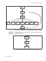
Host Node Topology....................................................................................................................................... 310
Single-host Per Port ................................................................................................................................. 310
Multiple-hosts Per Port............................................................................................................................. 310
Configuring the IGMP Snooping Parameters ................................................................................................. 311
Enabling IGMP Snooping ............................................................................................................................... 312
Disabling IGMP Snooping .............................................................................................................................. 313
Displaying IGMP Snooping............................................................................................................................. 314
9
Contents
Chapter 20: IGMP Snooping Commands ...................................................................................................315
CLEAR IP IGMP .............................................................................................................................................316
IP IGMP LIMIT ................................................................................................................................................317
IP IGMP QUERIER-TIMEOUT........................................................................................................................318
IP IGMP SNOOPING ......................................................................................................................................319
IP IGMP SNOOPING MROUTER ...................................................................................................................320
IP IGMP STATUS ...........................................................................................................................................321
NO IP IGMP SNOOPING................................................................................................................................322
NO IP IGMP SNOOPING MROUTER.............................................................................................................323
SHOW IP IGMP SNOOPING ..........................................................................................................................324
Section III: File System ...........................................................................................327
Chapter 21: File System ..............................................................................................................................329
Overview .........................................................................................................................................................330
Copying Boot Configuration Files ...................................................................................................................331
Renaming Boot Configuration Files ................................................................................................................332
Deleting Boot Configuration Files ...................................................................................................................333
Displaying the Specifications of the File System ............................................................................................334
Listing the Files in the File System .................................................................................................................335
Chapter 22: File System Commands ..........................................................................................................337
COPY ..............................................................................................................................................................338
DELETE ..........................................................................................................................................................339
DELETE FORCE ............................................................................................................................................340
DIR ..................................................................................................................................................................341
MOVE .............................................................................................................................................................342
SHOW FILE SYSTEMS ..................................................................................................................................343
Chapter 23: Boot Configuration Files ........................................................................................................345
Overview .........................................................................................................................................................346
Specifying the Active Boot Configuration File .................................................................................................347
Creating a New Boot Configuration File..........................................................................................................349
Displaying the Active Boot Configuration File .................................................................................................350
Chapter 24: Boot Configuration File Commands ......................................................................................351
BOOT CONFIG-FILE ......................................................................................................................................352
COPY RUNNING-CONFIG .............................................................................................................................354
COPY RUNNING-CONFIG STARTUP-CONFIG ............................................................................................355
ERASE STARTUP-CONFIG ...........................................................................................................................356
NO BOOT CONFIG-FILE................................................................................................................................357
SHOW BOOT..................................................................................................................................................358
SHOW STARTUP-CONFIG ............................................................................................................................360
WRITE ............................................................................................................................................................361
Chapter 25: File Transfers ...........................................................................................................................363
Overview .........................................................................................................................................................364
Uploading or Downloading Files with TFTP ....................................................................................................365
Downloading New Management Software with TFTP ..............................................................................365
Downloading Boot Configuration Files with TFTP ....................................................................................366
Uploading Files with TFTP .......................................................................................................................367
Uploading or Downloading Files with Zmodem...............................................................................................369
Downloading New Management Software with Zmodem.........................................................................369
Downloading Boot Configuration Files with Zmodem...............................................................................370
Uploading Files with Zmodem ..................................................................................................................371
10
AT-9000 Switch Command Line User’s Guide
Downloading Files with Enhanced Stacking................................................................................................... 373
Downloading New Management Software with Enhanced Stacking........................................................ 373
Chapter 26: File Transfer Commands ........................................................................................................ 375
COPY FILENAME ZMODEM ......................................................................................................................... 376
COPY FLASH TFTP....................................................................................................................................... 377
COPY TFTP FLASH....................................................................................................................................... 378
COPY ZMODEM ............................................................................................................................................ 380
UPLOAD IMAGE REMOTELIST .................................................................................................................... 381
Section IV: Event Messages .................................................................................... 383
Chapter 27: Event Log ................................................................................................................................ 385
Overview......................................................................................................................................................... 386
Displaying the Event Log................................................................................................................................ 387
Clearing the Event Log ................................................................................................................................... 388
Chapter 28: Event Log Commands ............................................................................................................ 389
CLEAR LOG BUFFERED............................................................................................................................... 390
LOG BUFFERED............................................................................................................................................ 391
SHOW LOG.................................................................................................................................................... 393
SHOW LOG CONFIG..................................................................................................................................... 396
SHOW LOG REVERSE.................................................................................................................................. 398
Chapter 29: Syslog Client ........................................................................................................................... 399
Overview......................................................................................................................................................... 400
Creating Syslog Server Definitions................................................................................................................. 401
Deleting Syslog Server Definitions ................................................................................................................. 404
Displaying the Syslog Server Definitions........................................................................................................ 405
Chapter 30: Syslog Client Commands ...................................................................................................... 407
LOG HOST ..................................................................................................................................................... 408
NO LOG HOST............................................................................................................................................... 410
SHOW LOG CONFIG..................................................................................................................................... 411
Section V: Port Trunks ........................................................................................... 413
Chapter 31: Static Port Trunks ................................................................................................................... 415
Overview......................................................................................................................................................... 416
Load Distribution Methods ....................................................................................................................... 416
Guidelines ................................................................................................................................................ 418
Creating New Static Port Trunks or Adding Ports To Existing Trunks............................................................ 420
Specifying the Load Distribution Method ........................................................................................................ 421
Removing Ports from Static Port Trunks or Deleting Trunks .......................................................................... 422
Displaying Static Port Trunks ......................................................................................................................... 423
Chapter 32: Static Port Trunk Commands ................................................................................................ 425
NO STATIC-CHANNEL-GROUP.................................................................................................................... 426
PORT-CHANNEL LOAD-BALANCE .............................................................................................................. 427
SHOW STATIC-CHANNEL-GROUP.............................................................................................................. 428
STATIC-CHANNEL-GROUP .......................................................................................................................... 429
11
Contents
Chapter 33: Link Aggregation Control Protocol (LACP) ..........................................................................431
Overview .........................................................................................................................................................432
LACP System Priority ...............................................................................................................................433
Base Port..................................................................................................................................................433
Aggregator ID Number .............................................................................................................................433
LACP Port Priority Value ..........................................................................................................................433
Load Distribution Methods........................................................................................................................434
Guidelines.................................................................................................................................................434
Creating New Aggregators..............................................................................................................................436
Setting the Load Distribution Method ..............................................................................................................437
Adding Ports to Aggregators ...........................................................................................................................438
Removing Ports from Aggregators..................................................................................................................439
Deleting Aggregators ......................................................................................................................................440
Displaying Aggregators ...................................................................................................................................441
Chapter 34: LACP Commands ....................................................................................................................443
CHANNEL-GROUP ........................................................................................................................................444
LACP SYSTEM-PRIORITY.............................................................................................................................446
NO CHANNEL-GROUP ..................................................................................................................................447
PORT-CHANNEL LOAD-BALANCE ...............................................................................................................448
SHOW ETHERCHANNEL ..............................................................................................................................450
SHOW ETHERCHANNEL DETAIL .................................................................................................................452
SHOW ETHERCHANNEL SUMMARY ...........................................................................................................453
SHOW LACP SYS-ID .....................................................................................................................................454
SHOW PORT ETHERCHANNEL....................................................................................................................455
Section VI: Spanning Tree Protocols .....................................................................457
Chapter 35: Spanning Tree and Rapid Spanning Tree Protocols ...........................................................459
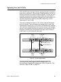
Overview .........................................................................................................................................................460
Bridge Priority and the Root Bridge ................................................................................................................461
Path Costs and Port Costs..............................................................................................................................462
Port Priority .....................................................................................................................................................463
Forwarding Delay and Topology Changes......................................................................................................464
Hello Time and Bridge Protocol Data Units (BPDU) .......................................................................................465
Point-to-Point and Edge Ports ........................................................................................................................466
Mixed STP and RSTP Networks .....................................................................................................................468
Spanning Tree and VLANs .............................................................................................................................469
RSTP BPDU Guard ........................................................................................................................................470
RSTP Loop Guard ..........................................................................................................................................472
Chapter 36: Spanning Tree Protocol (STP) ...............................................................................................477
Designating STP as the Active Spanning Tree Protocol.................................................................................478
Enabling the Spanning Tree Protocol .............................................................................................................479
Setting the Switch Parameters........................................................................................................................480
Setting the Port Parameters............................................................................................................................482
Disabling the Spanning Tree Protocol ............................................................................................................483
Restoring the Default Parameter Settings ......................................................................................................484
Displaying STP Settings .................................................................................................................................485
Chapter 37: STP Commands .......................................................................................................................487
NO SPANNING-TREE STP ENABLE .............................................................................................................489
SHOW SPANNING-TREE ..............................................................................................................................490
SPANNING-TREE FORWARD-TIME .............................................................................................................491
SPANNING-TREE HELLO-TIME ....................................................................................................................492
SPANNING-TREE MAX-AGE .........................................................................................................................493
12
AT-9000 Switch Command Line User’s Guide
SPANNING-TREE MODE STP ...................................................................................................................... 494
SPANNING-TREE PATH-COST .................................................................................................................... 495
SPANNING-TREE PRIORITY (Bridge Priority) .............................................................................................. 496
SPANNING-TREE PRIORITY (Port Priority).................................................................................................. 498
SPANNING-TREE STP ENABLE................................................................................................................... 500
SPANNING-TREE STP PURGE .................................................................................................................... 501
Chapter 38: Rapid Spanning Tree Protocol (RSTP) ................................................................................. 503
Designating RSTP as the Active Spanning Tree Protocol.............................................................................. 504
Enabling the Rapid Spanning Tree Protocol .................................................................................................. 505
Configuring the Switch Parameters ................................................................................................................ 506
Setting the Forward Time, Hello Time, and Max Age .............................................................................. 506
Setting the Bridge Priority ........................................................................................................................ 507
Enabling or Disabling BPDU Guard ......................................................................................................... 507
Configuring the Port Parameters .................................................................................................................... 509
Configuring Port Costs ............................................................................................................................. 509
Configuring Port Priorities ........................................................................................................................ 510
Designating Point-to-point and Shared Ports........................................................................................... 510
Designating Edge Ports ........................................................................................................................... 510
Enabling or Disabling RSTP Loop-guard ................................................................................................. 511
Enabling or Disabling BPDU Guard ......................................................................................................... 511
Disabling the Rapid Spanning Tree Protocol.................................................................................................. 513
Restoring the Default RSTP Settings ............................................................................................................. 514
Displaying RSTP Settings .............................................................................................................................. 515
Chapter 39: RSTP Commands .................................................................................................................... 517
NO SPANNING-TREE.................................................................................................................................... 519
NO SPANNING-TREE ERRDISABLE-TIMEOUT ENABLE ........................................................................... 520
NO SPANNING-TREE GUARD ROOT .......................................................................................................... 521
NO SPANNING-TREE LOOP-GUARD .......................................................................................................... 522
NO SPANNING-TREE PORTFAST ............................................................................................................... 523
NO SPANNING-TREE RSTP ENABLE.......................................................................................................... 524
SHOW SPANNING-TREE.............................................................................................................................. 525
SPANNING-TREE ERRDISABLE-TIMEOUT ENABLE.................................................................................. 527
SPANNING-TREE ERRDISABLE-TIMEOUT INTERVAL .............................................................................. 528
SPANNING-TREE FORCEVERSION ............................................................................................................ 529
SPANNING-TREE FORWARD-TIME............................................................................................................. 530
SPANNING-TREE GUARD ROOT................................................................................................................. 531
SPANNING-TREE HELLO-TIME ................................................................................................................... 532
SPANNING-TREE LINK-TYPE ...................................................................................................................... 533
SPANNING-TREE LOOP-GUARD................................................................................................................. 534
SPANNING-TREE MAX-AGE ........................................................................................................................ 535
SPANNING-TREE MODE RSTP.................................................................................................................... 536
SPANNING-TREE PATH-COST .................................................................................................................... 537
SPANNING-TREE PORTFAST...................................................................................................................... 538
SPANNING-TREE PRIORITY (Bridge Priority) .............................................................................................. 539
SPANNING-TREE PRIORITY (Port Priority).................................................................................................. 541
SPANNING-TREE RSTP ENABLE ................................................................................................................ 543
SPANNING-TREE RSTP PURGE.................................................................................................................. 544
13
Contents
Section VII: Virtual LANs ......................................................................................545
Chapter 40: Port-based and Tagged VLANs ..............................................................................................547
Overview .........................................................................................................................................................548
Port-based VLAN Overview ............................................................................................................................550
VLAN Name..............................................................................................................................................550
VLAN Identifier .........................................................................................................................................550
Untagged Ports.........................................................................................................................................551
Port VLAN Identifier..................................................................................................................................551
Guidelines to Creating a Port-based VLAN ..............................................................................................552
Drawbacks of Port-based VLANs .............................................................................................................552
Port-based Example 1 ..............................................................................................................................553
Port-based Example 2 ..............................................................................................................................554
Tagged VLAN Overview .................................................................................................................................556
Tagged and Untagged Ports ....................................................................................................................557
Port VLAN Identifier..................................................................................................................................557
Guidelines to Creating a Tagged VLAN ...................................................................................................557
Tagged VLAN Example ............................................................................................................................558
Creating VLANs ..............................................................................................................................................560
Adding Untagged Ports to VLANs...................................................................................................................561
Adding Tagged Ports to VLANs ......................................................................................................................563
Removing Untagged Ports from VLANs .........................................................................................................565
Removing Tagged Ports from VLANs .............................................................................................................566
Deleting VLANs...............................................................................................................................................567
Displaying the VLANs .....................................................................................................................................568
Chapter 41: Port-based and Tagged VLAN Commands ...........................................................................569
NO SWITCHPORT ACCESS VLAN ...............................................................................................................570
NO SWITCHPORT TRUNK ............................................................................................................................571
NO SWITCHPORT TRUNK NATIVE VLAN....................................................................................................572
NO VLAN ........................................................................................................................................................573
SHOW VLAN ..................................................................................................................................................574
SWITCHPORT ACCESS VLAN......................................................................................................................576
SWITCHPORT MODE ACCESS ....................................................................................................................578
SWITCHPORT MODE TRUNK.......................................................................................................................579
SWITCHPORT TRUNK ALLOWED VLAN......................................................................................................581
SWITCHPORT TRUNK NATIVE VLAN ..........................................................................................................584
SWITCHPORT VOICE DSCP.........................................................................................................................586
SWITCHPORT VOICE VLAN PRIORITY .......................................................................................................587
VLAN...............................................................................................................................................................588
Chapter 42: GARP VLAN Registration Protocol ........................................................................................591
Overview .........................................................................................................................................................592
Guidelines .......................................................................................................................................................595
GVRP and Network Security...........................................................................................................................596
GVRP-inactive Intermediate Switches ............................................................................................................597
Enabling GVRP on the Switch ........................................................................................................................598
Enabling GIP on the Switch ............................................................................................................................599
Enabling GVRP on the Ports ..........................................................................................................................600
Setting the GVRP Timers................................................................................................................................601
Disabling GVRP on the Ports..........................................................................................................................602
Disabling GIP on the Switch ...........................................................................................................................603
Disabling GVRP on the Switch .......................................................................................................................604
Restoring the GVRP Default Settings .............................................................................................................605
Displaying GVRP ............................................................................................................................................606
14
AT-9000 Switch Command Line User’s Guide
Chapter 43: GARP VLAN Registration Protocol Commands .................................................................. 607
GVRP APPLICANT STATE ACTIVE.............................................................................................................. 609
GVRP APPLICANT STATE NORMAL ........................................................................................................... 610
GVRP ENABLE .............................................................................................................................................. 611
GVRP REGISTRATION ................................................................................................................................. 612
GVRP TIMER JOIN ........................................................................................................................................ 613
GVRP TIMER LEAVE..................................................................................................................................... 614
GVRP TIMER LEAVEALL .............................................................................................................................. 615
NO GVRP ENABLE........................................................................................................................................ 616
PURGE GVRP................................................................................................................................................ 617
SHOW GVRP APPLICANT ............................................................................................................................ 618
SHOW GVRP CONFIGURATION .................................................................................................................. 619
SHOW GVRP MACHINE................................................................................................................................ 620
SHOW GVRP STATISTICS ........................................................................................................................... 621
SHOW GVRP TIMER ..................................................................................................................................... 623
Chapter 44: MAC Address-based VLANs .................................................................................................. 625
Overview......................................................................................................................................................... 626
Egress Ports............................................................................................................................................. 626
VLANs that Span Switches ...................................................................................................................... 629
VLAN Hierarchy ....................................................................................................................................... 630
Guidelines....................................................................................................................................................... 631
General Steps................................................................................................................................................. 632
Creating MAC Address-based VLANs............................................................................................................ 633
Adding MAC Addresses to VLANs and Designating Egress Ports................................................................. 634
Removing MAC Addresses ............................................................................................................................ 635
Deleting VLANs .............................................................................................................................................. 636
Displaying VLANs........................................................................................................................................... 637
Example of Creating a MAC Address-based VLAN ....................................................................................... 638
Chapter 45: MAC Address-based VLAN Commands ............................................................................... 641
NO VLAN........................................................................................................................................................ 642
NO VLAN MACADDRESS (Global Configuration Mode) ............................................................................... 643
NO VLAN MACADDRESS (Port Interface Mode) .......................................................................................... 644
SHOW VLAN MACADDRESS........................................................................................................................ 645
VLAN MACADDRESS.................................................................................................................................... 647
VLAN SET MACADDRESS (Global Configuration Mode).............................................................................. 649
VLAN SET MACADDRESS (Port Interface Mode)......................................................................................... 651
Chapter 46: Private Port VLANs ................................................................................................................. 653
Overview......................................................................................................................................................... 654
Host Ports ................................................................................................................................................ 654
Uplink Port................................................................................................................................................ 654
Guidelines....................................................................................................................................................... 655
Creating Private VLANs.................................................................................................................................. 656
Adding Host and Uplink Ports......................................................................................................................... 657
Deleting VLANs .............................................................................................................................................. 658
Displaying Private VLANs............................................................................................................................... 659
Chapter 47: Private Port VLAN Commands .............................................................................................. 661
NO VLAN........................................................................................................................................................ 662
PRIVATE-VLAN.............................................................................................................................................. 663
SHOW VLAN PRIVATE-VLAN ....................................................................................................................... 664
SWITCHPORT MODE PRIVATE-VLAN HOST.............................................................................................. 665
SWITCHPORT MODE PRIVATE-VLAN PROMISCUOUS ............................................................................ 666
15
Contents
Section VIII: Port Security .....................................................................................667
Chapter 48: MAC Address-based Port Security ........................................................................................669
Overview .........................................................................................................................................................670
Static Versus Dynamic Addresses ...........................................................................................................670
Intrusion Actions .......................................................................................................................................670
Guidelines.................................................................................................................................................671
Configuring Ports ............................................................................................................................................672
Enabling MAC Address-based Security on Ports ...........................................................................................674
Disabling MAC Address-based Security on Ports...........................................................................................675
Displaying Port Settings ..................................................................................................................................676
Chapter 49: MAC Address-based Port Security Commands ...................................................................677
NO SWITCHPORT PORT-SECURITY ...........................................................................................................678
NO SWITCHPORT PORT-SECURITY AGING...............................................................................................679
SHOW PORT-SECURITY INTERFACE .........................................................................................................680
SHOW PORT-SECURITY INTRUSION INTERFACE ....................................................................................683
SWITCHPORT PORT-SECURITY..................................................................................................................684
SWITCHPORT PORT-SECURITY AGING .....................................................................................................685
SWITCHPORT PORT-SECURITY MAXIMUM ...............................................................................................686
SWITCHPORT PORT-SECURITY VIOLATION .............................................................................................687
Chapter 50: 802.1x Port-based Network Access Control .........................................................................689
Overview .........................................................................................................................................................690
Authentication Process ...................................................................................................................................691
Authentication Methods ..................................................................................................................................692
Operational Settings .......................................................................................................................................693
Authenticator Port Operating Modes...............................................................................................................694
Single Host Mode .....................................................................................................................................694
Multiple Host Mode...................................................................................................................................694
Multiple Supplicant Mode .........................................................................................................................696
Supplicant and VLAN Associations.................................................................................................................698
Single Host Mode .....................................................................................................................................699
Multiple Host Mode...................................................................................................................................699
Multiple Supplicant Mode .........................................................................................................................699
Supplicant VLAN Attributes on the RADIUS Server .................................................................................699
Guest VLAN ....................................................................................................................................................701
RADIUS Accounting........................................................................................................................................702
General Steps .................................................................................................................................................703
Guidelines .......................................................................................................................................................705
Enabling 802.1x Port-Based Network Access Control on the Switch .............................................................707
Configuring Authenticator Ports ......................................................................................................................708
Designating Authenticator Ports ...............................................................................................................708
Designating the Authentication Methods ..................................................................................................708
Configuring the Operating Modes.............................................................................................................709
Configuring Reauthentication..........................................................................................................................711
Removing the Authenticator Role from Ports..................................................................................................712
Disabling 802.1x Port-Based Network Access Control on the Switch.............................................................713
Displaying Authenticator Ports ........................................................................................................................714
Displaying EAP Packet Statistics ....................................................................................................................715
Chapter 51: 802.1x Port-based Network Access Control Commands ....................................................717
AAA AUTHENTICATION DOT1X DEFAULT GROUP RADIUS .....................................................................720
AUTH DYNAMIC-VLAN-CREATION ..............................................................................................................721
AUTH GUEST-VLAN ......................................................................................................................................723
16
AT-9000 Switch Command Line User’s Guide
AUTH HOST-MODE....................................................................................................................................... 724
AUTH REAUTHENTICATION ........................................................................................................................ 726
AUTH TIMEOUT QUIET-PERIOD.................................................................................................................. 727
AUTH TIMEOUT REAUTH-PERIOD.............................................................................................................. 728
AUTH TIMEOUT SERVER-TIMEOUT ........................................................................................................... 729
AUTH TIMEOUT SUPP-TIMEOUT ................................................................................................................ 730
AUTH-MAC ENABLE ..................................................................................................................................... 731
AUTH-MAC REAUTH-RELEARNING ............................................................................................................ 732
DOT1X CONTROL-DIRECTION .................................................................................................................... 733
DOT1X EAP ................................................................................................................................................... 735
DOT1X INITIALIZE INTERFACE ................................................................................................................... 737
DOT1X MAX-REAUTH-REQ.......................................................................................................................... 738
DOT1X PORT-CONTROL AUTO................................................................................................................... 739
DOT1X PORT-CONTROL FORCE-AUTHORIZED........................................................................................ 740
DOT1X PORT-CONTROL FORCE-UNAUTHORIZED .................................................................................. 741
DOT1X TIMEOUT TX-PERIOD...................................................................................................................... 742
NO AAA AUTHENTICATION DOT1X DEFAULT GROUP RADIUS .............................................................. 743
NO AUTH DYNAMIC-VLAN-CREATION ....................................................................................................... 744
NO AUTH GUEST-VLAN ............................................................................................................................... 745
NO AUTH REAUTHENTICATION.................................................................................................................. 746
NO AUTH-MAC ENABLE ............................................................................................................................... 747
NO DOT1X PORT-CONTROL ....................................................................................................................... 748
SHOW AUTH-MAC INTERFACE ................................................................................................................... 749
SHOW AUTH-MAC SESSIONSTATISTICS INTERFACE ............................................................................. 750
SHOW AUTH-MAC STATISTICS INTERFACE ............................................................................................. 751
SHOW AUTH-MAC SUPPLICANT INTERFACE ........................................................................................... 752
SHOW DOT1X ............................................................................................................................................... 753
SHOW DOT1X INTERFACE .......................................................................................................................... 754
SHOW DOT1X SESSIONSTATISTICS INTERFACE .................................................................................... 755
SHOW DOT1X STATISTICS INTERFACE .................................................................................................... 756
SHOW DOT1X SUPPLICANT INTERFACE .................................................................................................. 757
Section IX: Simple Network Management Protocols ........................................... 759
Chapter 52: SNMPv1 and SNMPv2c ........................................................................................................... 761
Overview......................................................................................................................................................... 762
Enabling SNMPv1 and SNMPv2c .................................................................................................................. 764
Creating Community Strings........................................................................................................................... 765
Adding or Removing IP Addresses of Trap or Inform Receivers.................................................................... 766
Deleting Community Strings ........................................................................................................................... 768
Disabling SNMPv1 and SNMPv2c.................................................................................................................. 769
Displaying SNMPv1 and SNMPv2c................................................................................................................ 770
Chapter 53: SNMPv1 and SNMPv2c Commands ...................................................................................... 773
NO SNMP-SERVER....................................................................................................................................... 775
NO SNMP-SERVER COMMUNITY................................................................................................................ 776
NO SNMP-SERVER ENABLE TRAP AUTH .................................................................................................. 777
NO SNMP-SERVER HOST............................................................................................................................ 778
NO SNMP-SERVER VIEW............................................................................................................................. 780
SHOW RUNNING-CONFIG SNMP ................................................................................................................ 781
SHOW SNMP-SERVER ................................................................................................................................. 782
SHOW SNMP-SERVER COMMUNITY.......................................................................................................... 783
SHOW SNMP-SERVER VIEW....................................................................................................................... 785
SNMP-SERVER ............................................................................................................................................. 786
SNMP-SERVER COMMUNITY ...................................................................................................................... 787
17
Contents
SNMP-SERVER ENABLE TRAP AUTH .........................................................................................................788
SNMP-SERVER HOST...................................................................................................................................789
SNMP-SERVER VIEW ...................................................................................................................................791
Chapter 54: SNMPv3 Commands ...............................................................................................................793
NO SNMP-SERVER .......................................................................................................................................795
NO SNMP-SERVER GROUP .........................................................................................................................796
NO SNMP-SERVER HOST ............................................................................................................................797
NO SNMP-SERVER USER ............................................................................................................................798
NO SNMP-SERVER VIEW .............................................................................................................................799
SHOW SNMP-SERVER .................................................................................................................................800
SHOW SNMP-SERVER GROUP ...................................................................................................................801
SHOW SNMP-SERVER HOST.......................................................................................................................802
SHOW SNMP-SERVER USER.......................................................................................................................803
SHOW SNMP-SERVER VIEW .......................................................................................................................804
SNMP-SERVER..............................................................................................................................................805
SNMP-SERVER ENGINEID LOCAL...............................................................................................................806
SNMP-SERVER GROUP ...............................................................................................................................807
SNMP-SERVER HOST...................................................................................................................................809
SNMP-SERVER USER...................................................................................................................................810
SNMP-SERVER VIEW ...................................................................................................................................812
Section X: Network Management ..........................................................................815
Chapter 55: sFlow Agent .............................................................................................................................817
Overview .........................................................................................................................................................818
Ingress Packet Samples...........................................................................................................................818
Packet Counters .......................................................................................................................................818
sFlow Collectors .......................................................................................................................................819
Guidelines.................................................................................................................................................819
Configuring the sFlow Agent ...........................................................................................................................820
Configuring the Ports ......................................................................................................................................821
Configuring the Sampling Rate.................................................................................................................821
Configuring the Polling Interval.................................................................................................................821
Selecting the sFlow Collector ...................................................................................................................822
Enabling the sFlow Agent ...............................................................................................................................824
Disabling the sFlow Agent ..............................................................................................................................825
Displaying the sFlow Agent.............................................................................................................................826
Configuration Example....................................................................................................................................827
Chapter 56: sFlow Agent Commands ........................................................................................................831
NO SFLOW ENABLE......................................................................................................................................832
SET SFLOW COLLECTOR IP ........................................................................................................................833
SFLOW COLLECTOR IP ................................................................................................................................834
SFLOW ENABLE ............................................................................................................................................835
SFLOW POLLING-INTERVAL ........................................................................................................................836
SFLOW SAMPLING-RATE .............................................................................................................................837
SHOW SFLOW ...............................................................................................................................................838
SHOW SFLOW DATABASE ...........................................................................................................................840
Chapter 57: LLDP and LLDP-MED ..............................................................................................................843
Overview .........................................................................................................................................................844
Mandatory LLDP TLVs .............................................................................................................................845
Optional LLDP TLVs.................................................................................................................................845
Optional LLDP-MED TLVs........................................................................................................................847
18
AT-9000 Switch Command Line User’s Guide
Enabling LLDP and LLDP-MED on the Switch............................................................................................... 850
Configuring Ports to Only Receive LLDP and LLDP-MED TLVs.................................................................... 851
Configuring Ports to Send Only Mandatory LLDP TLVs................................................................................. 852
Configuring Ports to Send Optional LLDP TLVs............................................................................................. 854
Configuring Ports to Send Optional LLDP-MED TLVs ................................................................................... 856
Configuring Ports to Send LLDP-MED Civic Location TLVs .......................................................................... 858
Configuring Ports to Send LLDP-MED Coordinate Location TLVs................................................................. 862
Configuring Ports to Send LLDP-MED ELIN Location TLVs .......................................................................... 866
Removing LLDP TLVs from Ports .................................................................................................................. 868
Removing LLDP-MED TLVs from Ports ......................................................................................................... 869
Deleting LLDP-MED Location Entries ............................................................................................................ 870
Disabling LLDP and LLDP-MED on the Switch .............................................................................................. 871
Displaying General LLDP Settings ................................................................................................................. 872
Displaying Port Settings ................................................................................................................................. 873
Displaying or Clearing Neighbor Information.................................................................................................. 874
Displaying Port TLVs ...................................................................................................................................... 876
Displaying and Clearing Statistics .................................................................................................................. 877
Chapter 58: LLDP and LLDP-MED Commands ......................................................................................... 879
CLEAR LLDP STATISTICS............................................................................................................................ 882
CLEAR LLDP TABLE ..................................................................................................................................... 883
LLDP HOLDTIME-MULTIPLIER..................................................................................................................... 884
LLDP LOCATION ........................................................................................................................................... 885
LLDP MANAGEMENT-ADDRESS ................................................................................................................. 887
LLDP MED-NOTIFICATIONS......................................................................................................................... 889
LLDP MED-TLV-SELECT............................................................................................................................... 890
LLDP NON-STRICT-MED-TLV-ORDER-CHECK .......................................................................................... 892
LLDP NOTIFICATIONS.................................................................................................................................. 893
LLDP NOTIFICATION-INTERVAL ................................................................................................................. 894
LLDP REINIT.................................................................................................................................................. 895
LLDP RUN...................................................................................................................................................... 896
LLDP TIMER .................................................................................................................................................. 897
LLDP TLV-SELECT........................................................................................................................................ 898
LLDP TRANSMIT RECEIVE .......................................................................................................................... 901
LLDP TX-DELAY ............................................................................................................................................ 902
LOCATION CIVIC-LOCATION ....................................................................................................................... 903
LOCATION COORD-LOCATION ................................................................................................................... 906
LOCATION ELIN-LOCATION......................................................................................................................... 909
NO LLDP MED-NOTIFICATIONS .................................................................................................................. 910
NO LLDP MED-TLV-SELECT ........................................................................................................................ 911
NO LLDP NOTIFICATIONS ........................................................................................................................... 913
NO LLDP RUN ............................................................................................................................................... 914
NO LLDP TLV-SELECT ................................................................................................................................. 915
NO LLDP TRANSMIT RECEIVE .................................................................................................................... 916
NO LOCATION............................................................................................................................................... 917
SHOW LLDP .................................................................................................................................................. 919
SHOW LLDP INTERFACE ............................................................................................................................. 921
SHOW LLDP LOCAL-INFO INTERFACE ...................................................................................................... 923
SHOW LLDP NEIGHBORS DETAIL .............................................................................................................. 925
SHOW LLDP NEIGHBORS INTERFACE ...................................................................................................... 929
SHOW LLDP STATISTICS............................................................................................................................. 931
SHOW LLDP STATISTICS INTERFACE ....................................................................................................... 933
SHOW LOCATION ......................................................................................................................................... 935
19
Contents
Chapter 59: Address Resolution Protocol (ARP) ......................................................................................937
Overview .........................................................................................................................................................938
Adding Static ARP Entries ..............................................................................................................................939
Deleting Static or Dynamic ARP Entries .........................................................................................................940
Clearing the ARP Table ..................................................................................................................................941
Displaying the ARP Table ...............................................................................................................................942
Chapter 60: ARP Commands ......................................................................................................................943
ARP.................................................................................................................................................................944
CLEAR ARP-CACHE ......................................................................................................................................946
NO ARP ..........................................................................................................................................................947
SHOW ARP ....................................................................................................................................................948
Chapter 61: RMON .......................................................................................................................................951
Overview .........................................................................................................................................................952
RMON Port Statistics ......................................................................................................................................953
Adding Statistics Groups ..........................................................................................................................953
Viewing Statistics Groups.........................................................................................................................954
Deleting Statistics Groups ........................................................................................................................954
RMON Histories ..............................................................................................................................................955
Adding History Groups .............................................................................................................................955
Displaying History Groups ........................................................................................................................956
Deleting History Groups ...........................................................................................................................957
RMON Alarms .................................................................................................................................................958
Creating RMON Statistics Groups............................................................................................................959
Creating RMON Events ............................................................................................................................959
Creating RMON Alarms............................................................................................................................960
Creating an Alarm - Example 1 ................................................................................................................961
Creating an Alarm - Example 2 ................................................................................................................963
Chapter 62: RMON Commands ...................................................................................................................967
NO RMON ALARM .........................................................................................................................................969
NO RMON COLLECTION HISTORY..............................................................................................................970
NO RMON COLLECTION STATS ..................................................................................................................971
NO RMON EVENT..........................................................................................................................................972
RMON ALARM................................................................................................................................................973
RMON COLLECTION HISTORY ....................................................................................................................977
RMON COLLECTION STATS ........................................................................................................................979
RMON EVENT LOG .......................................................................................................................................980
RMON EVENT LOG TRAP .............................................................................................................................981
RMON EVENT TRAP .....................................................................................................................................982
SHOW RMON ALARM ...................................................................................................................................983
SHOW RMON EVENT ....................................................................................................................................985
SHOW RMON HISTORY ................................................................................................................................987
SHOW RMON STATISTICS ...........................................................................................................................989
Chapter 63: Access Control Lists (ACLs) ..................................................................................................991
Overview .........................................................................................................................................................992
Filtering Criteria ........................................................................................................................................992
Actions......................................................................................................................................................992
ID Numbers ..............................................................................................................................................992
How Ingress Packets are Compared Against ACLs .................................................................................993
Guidelines.................................................................................................................................................993
Creating ACLs.................................................................................................................................................995
Adding ACLs to Ports.................................................................................................................................... 1000
Removing ACLs from Ports .......................................................................................................................... 1001
20
AT-9000 Switch Command Line User’s Guide
Deleting ACLs from the Switch..................................................................................................................... 1002
Displaying the ACLs ..................................................................................................................................... 1003
Chapter 64: ACL Commands .................................................................................................................... 1005
ACCESS-LIST (MAC Address) .................................................................................................................... 1007
ACCESS-LIST ICMP .................................................................................................................................... 1010
ACCESS-LIST IP.......................................................................................................................................... 1014
ACCESS-LIST PROTO ................................................................................................................................ 1018
ACCESS-LIST TCP...................................................................................................................................... 1023
ACCESS-LIST UDP ..................................................................................................................................... 1027
IP ACCESS-GROUP .................................................................................................................................... 1031
MAC ACCESS-GROUP ............................................................................................................................... 1032
NO ACCESS-LIST........................................................................................................................................ 1033
NO IP ACCESS-GROUP.............................................................................................................................. 1034
NO MAC ACCESS-GROUP ......................................................................................................................... 1035
SHOW ACCESS-LIST.................................................................................................................................. 1036
SHOW INTERFACE ACCESS-GROUP....................................................................................................... 1037
Chapter 65: Quality of Service (QOS) Commands ................................................................................. 1039
MLS QOS ENABLE ...................................................................................................................................... 1041
MLS QOS MAP COS-QUEUE...................................................................................................................... 1042
MLS QOS MAP DSCP-QUEUE ................................................................................................................... 1044
MLS QOS QUEUE ....................................................................................................................................... 1046
MLS QOS SET COS .................................................................................................................................... 1047
MLS QOS SET DSCP .................................................................................................................................. 1048
MLS QOS TRUST COS ............................................................................................................................... 1049
MLS QOS TRUST DSCP ............................................................................................................................. 1050
NO MLS QOS ENABLE................................................................................................................................ 1051
NO WRR-QUEUE WEIGHT ......................................................................................................................... 1052
SHOW MLS QOS INTERFACE.................................................................................................................... 1053
SHOW MLS QOS MAPS COS-QUEUE ....................................................................................................... 1056
SHOW MLS QOS MAPS DSCP-QUEUE..................................................................................................... 1057
WRR-QUEUE WEIGHT................................................................................................................................ 1059
Section XI: Management Security ....................................................................... 1061
Chapter 66: Local Manager Accounts ..................................................................................................... 1063
Overview....................................................................................................................................................... 1064
Command Mode Restriction................................................................................................................... 1064
Password Encryption ............................................................................................................................. 1065
Creating Local Manager Accounts ............................................................................................................... 1066
Deleting Local Manager Accounts................................................................................................................ 1068
Activating Command Mode Restriction ........................................................................................................ 1069
Disabling Command Mode Restriction ......................................................................................................... 1070
Encrypting Local Manager Account Passwords ........................................................................................... 1071
Displaying the Local Manager Accounts ...................................................................................................... 1072
Chapter 67: Local Manager Account Commands ................................................................................... 1073
ENABLE PASSWORD ................................................................................................................................. 1074
NO ENABLE PASSWORD ........................................................................................................................... 1075
NO USERNAME........................................................................................................................................... 1076
SERVICE PASSWORD-ENCRYPTION ....................................................................................................... 1077
USERNAME ................................................................................................................................................. 1078
21
Contents
Chapter 68: Telnet Server ......................................................................................................................... 1081
Overview ....................................................................................................................................................... 1082
Enabling the Telnet Server ........................................................................................................................... 1083
Disabling the Telnet Server........................................................................................................................... 1084
Displaying the Telnet Server ......................................................................................................................... 1085
Chapter 69: Telnet Server Commands ..................................................................................................... 1087
NO SERVICE TELNET ................................................................................................................................. 1088
SERVICE TELNET ....................................................................................................................................... 1089
SHOW TELNET ............................................................................................................................................ 1090
Chapter 70: Telnet Client ........................................................................................................................... 1091
Overview ....................................................................................................................................................... 1092
Starting a Remote Management Session with the Telnet Client................................................................... 1093
Chapter 71: Telnet Client Commands ...................................................................................................... 1095
TELNET ........................................................................................................................................................ 1096
TELNET6 ...................................................................................................................................................... 1097
Chapter 72: Secure Shell (SSH) Server .................................................................................................... 1099
Overview ....................................................................................................................................................... 1100
Algorithms............................................................................................................................................... 1100
Active Encryption Key............................................................................................................................. 1100
Support for SSH ............................................................................................................................................ 1101
Guidelines............................................................................................................................................... 1101
SSH and Enhanced Stacking........................................................................................................................ 1103
Creating the Encryption Key Pair .................................................................................................................. 1105
Enabling the SSH Server .............................................................................................................................. 1106
Disabling the SSH Server ............................................................................................................................. 1107
Deleting Encryption Keys .............................................................................................................................. 1108
Displaying the SSH Server ........................................................................................................................... 1109
Chapter 73: SSH Server Commands ........................................................................................................ 1111
CRYPTO KEY DESTROY HOSTKEY .......................................................................................................... 1112
CRYPTO KEY GENERATE HOSTKEY ........................................................................................................ 1113
NO SERVICE SSH ....................................................................................................................................... 1115
SERVICE SSH .............................................................................................................................................. 1116
SHOW SSH KEY HOSTKEY ........................................................................................................................ 1117
SHOW SSH SERVER................................................................................................................................... 1118
SSH SERVER LOGIN-TIMEOUT ................................................................................................................. 1119
SSH SERVER MAX-STARTUPS.................................................................................................................. 1120
SSH SERVER SESSION-TIMEOUT............................................................................................................. 1121
Chapter 74: Non-secure HTTP Web Browser Server .............................................................................. 1123
Overview ....................................................................................................................................................... 1124
Enabling the Web Browser Server ................................................................................................................ 1125
Setting the Protocol Port Number ................................................................................................................. 1126
Disabling the Web Browser Server ............................................................................................................... 1127
Displaying the Web Browser Server ............................................................................................................. 1128
Chapter 75: Non-secure HTTP Web Browser Server Commands ......................................................... 1129
HTTP SERVER ............................................................................................................................................. 1130
IP HTTP PORT ............................................................................................................................................. 1131
NO HTTP SERVER ...................................................................................................................................... 1132
SHOW IP HTTP ............................................................................................................................................ 1133
22
AT-9000 Switch Command Line User’s Guide
Chapter 76: Secure HTTPS Web Browser Server ................................................................................... 1135
Overview....................................................................................................................................................... 1136
Certificates ............................................................................................................................................. 1136
Distinguished Name ............................................................................................................................... 1137
Guidelines .............................................................................................................................................. 1138
Creating a Self-signed Certificate................................................................................................................. 1139
Configuring the HTTPS Web Server for a Certificate Issued by a CA.......................................................... 1142
Enabling the Web Browser Server ............................................................................................................... 1146
Disabling the Web Browser Server............................................................................................................... 1147
Displaying the Web Browser Server............................................................................................................. 1148
Chapter 77: Secure HTTPS Web Browser Server Commands .............................................................. 1149
CRYPTO CERTIFICATE DESTROY............................................................................................................ 1150
CRYPTO CERTIFICATE GENERATE ......................................................................................................... 1151
CRYPTO CERTIFICATE IMPORT ............................................................................................................... 1153
CRYPTO CERTIFICATE REQUEST............................................................................................................ 1154
HTTPS SERVER .......................................................................................................................................... 1156
IP HTTPS CERTIFICATE............................................................................................................................. 1157
NO HTTPS SERVER.................................................................................................................................... 1158
SHOW CRYPTO CERTIFICATE.................................................................................................................. 1159
SHOW IP HTTPS ......................................................................................................................................... 1160
Chapter 78: RADIUS and TACACS+ Clients ............................................................................................ 1163
Overview....................................................................................................................................................... 1164
Remote Manager Accounts .......................................................................................................................... 1165
Guidelines .............................................................................................................................................. 1167
Managing the RADIUS Client ....................................................................................................................... 1168
Adding IP Addresses of RADIUS Servers.............................................................................................. 1168
Specifying a RADIUS Global Encryption Key ........................................................................................ 1169
Specifying the Server Timeout ............................................................................................................... 1169
Deleting Server IP Addresses ................................................................................................................ 1169
Displaying the RADIUS Client................................................................................................................ 1170
Managing the TACACS+ Client .................................................................................................................... 1171
Adding IP Addresses of TACACS+ Servers .......................................................................................... 1171
Deleting IP Addresses of TACACS+ Servers ........................................................................................ 1171
Displaying the TACACS+ Client............................................................................................................. 1172
Configuring Remote Authentication of Manager Accounts........................................................................... 1173
Chapter 79: RADIUS and TACACS+ Client Commands ......................................................................... 1177
AUTHENTICATION PURGE ........................................................................................................................ 1179
LOGIN AUTHENTICATION.......................................................................................................................... 1180
NO LOGIN AUTHENTICATION ................................................................................................................... 1182
NO RADIUS-ACC ENABLE.......................................................................................................................... 1183
NO RADIUS-SERVER HOST....................................................................................................................... 1184
NO SERVER-BASED AUTHENTICATION RADIUS.................................................................................... 1185
NO SERVER-BASED AUTHENTICATION TACACS................................................................................... 1186
NO TACACS-SERVER HOST...................................................................................................................... 1187
RADIUS-ACC ENABLE ................................................................................................................................ 1188
RADIUS-SERVER HOST ............................................................................................................................. 1189
RADIUS-SERVER HOST ACCT-PORT ....................................................................................................... 1191
RADIUS-SERVER KEY................................................................................................................................ 1193
RADIUS-SERVER TIMEOUT....................................................................................................................... 1194
SERVER-BASED AUTHENTICATION RADIUS .......................................................................................... 1195
SERVER-BASED AUTHENTICATION TACACS ......................................................................................... 1196
SHOW RADIUS............................................................................................................................................ 1197
SHOW TACACS........................................................................................................................................... 1199
23
Contents
TACACS-SERVER HOST ............................................................................................................................ 1201
Appendix A: System Monitoring Commands ..........................................................................................1203
SHOW CPU .................................................................................................................................................. 1204
SHOW CPU HISTORY ................................................................................................................................. 1205
SHOW CPU USER-THREADS ..................................................................................................................... 1206
SHOW MEMORY.......................................................................................................................................... 1207
SHOW MEMORY ALLOCATION .................................................................................................................. 1208
SHOW MEMORY HISTORY......................................................................................................................... 1209
SHOW MEMORY POOLS ............................................................................................................................ 1210
SHOW PROCESS ........................................................................................................................................ 1211
SHOW SERIALNUMBER ............................................................................................................................. 1212
SHOW SYSTEM INTERRUPTS ................................................................................................................... 1213
SHOW TECH-SUPPORT ............................................................................................................................. 1214
Appendix B: Management Software Default Settings ............................................................................ 1217
Boot Configuration File ................................................................................................................................. 1218
Class of Service ............................................................................................................................................ 1219
Console Port ................................................................................................................................................. 1220
802.1x Port-Based Network Access Control ................................................................................................. 1221
Enhanced Stacking ....................................................................................................................................... 1222
GVRP ............................................................................................................................................................ 1223
IGMP Snooping............................................................................................................................................. 1224
Link Layer Discovery Protocol (LLDP and LLDP-MED) ................................................................................ 1225
MAC Address-based Port Security ............................................................................................................... 1226
MAC Address Table ...................................................................................................................................... 1227
Management IP Address .............................................................................................................................. 1228
Manager Account .......................................................................................................................................... 1229
Port Settings ................................................................................................................................................. 1230
RADIUS Client .............................................................................................................................................. 1231
Remote Manager Account Authentication .................................................................................................... 1232
RMON ........................................................................................................................................................... 1233
Secure Shell Server ...................................................................................................................................... 1234
sFlow Agent .................................................................................................................................................. 1235
Simple Network Management Protocol (SNMPv1, SNMPv2c and SNMPv3) ............................................... 1236
Simple Network Time Protocol...................................................................................................................... 1237
Spanning Tree Protocols (STP and RSTP) .................................................................................................. 1238
Spanning Tree Status............................................................................................................................. 1238
Spanning Tree Protocol.......................................................................................................................... 1238
Rapid Spanning Tree Protocol ............................................................................................................... 1238
System Name ............................................................................................................................................... 1240
TACACS+ Client ........................................................................................................................................... 1241
Telnet Server ................................................................................................................................................ 1242
VLANs ........................................................................................................................................................... 1243
Web Server ...................................................................................................................................................1244
Command Index ......................................................................................................................................... 1245
24
Tables
Table 1. AlliedWare Plus Modes ......................................................................................................................................... 41
Table 2. Basic Command Line Commands ........................................................................................................................ 73
Table 3. Basic Switch Management Commands .............................................................................................................. 107
Table 4. SHOW SWITCH Command ................................................................................................................................ 128
Table 5. SHOW USERS Command .................................................................................................................................. 131
Table 6. Port Parameter Commands ................................................................................................................................ 155
Table 7. SHOW FLOWCONTROL INTERFACE Command ............................................................................................. 184
Table 8. SHOW INTERFACE Command .......................................................................................................................... 186
Table 9. SHOW INTERFACE STATUS Command .......................................................................................................... 188
Table 10. SHOW PLATFORM TABLE PORT COUNTERS Command ............................................................................ 190
Table 11. Features that Require an IP Management Address .........................................................................................200
Table 12. Management IP Address Commands ............................................................................................................... 213
Table 13. SHOW IP INTERFACE Command ................................................................................................................... 229
Table 14. SHOW IP ROUTE Command ........................................................................................................................... 230
Table 15. SHOW IPV6 INTERFACE Command ............................................................................................................... 232
Table 16. SNTP Daylight Savings Time and UTC Offset Commands .............................................................................. 237
Table 17. Simple Network Time Protocol Commands ...................................................................................................... 243
Table 18. SHOW NTP ASSOCIATIONS Command ......................................................................................................... 251
Table 19. MAC Address Table Commands ...................................................................................................................... 263
Table 20. SHOW MAC ADDRESS-TABLE Command - Unicast Addresses .................................................................... 272
Table 21. SHOW MAC ADDRESS-TABLE Command - Multicast Addresses .................................................................. 272
Table 22. Enhanced Stacking Commands ....................................................................................................................... 285
Table 23. SHOW ESTACK Command .............................................................................................................................. 292
Table 24. Port Mirror Commands ..................................................................................................................................... 301
Table 25. SHOW MIRROR Command ............................................................................................................................. 304
Table 26. IGMP Snooping Parameters ............................................................................................................................. 311
Table 27. Internet Group Management Protocol Snooping Commands ...........................................................................315
Table 28. SHOW IP IGMP SNOOPING Command .......................................................................................................... 325
Table 29. File Extensions and File Types ......................................................................................................................... 330
Table 30. File System Commands .................................................................................................................................... 337
Table 31. SHOW FILE SYSTEMS Command .................................................................................................................. 343
Table 32. Boot Configuration File Commands .................................................................................................................. 351
Table 33. SHOW BOOT Command .................................................................................................................................. 358
Table 34. File Transfer Commands .................................................................................................................................. 375
Table 35. Event Log Commands ...................................................................................................................................... 389
Table 36. Event Message Severity Levels ........................................................................................................................ 391
Table 37. SHOW LOG Command .................................................................................................................................... 393
Table 38. Management Software Modules ....................................................................................................................... 394
Table 39. SHOW LOG CONFIG Command ..................................................................................................................... 396
Table 40. Event Message Severity Levels ........................................................................................................................ 401
Table 41. Program Abbreviations ..................................................................................................................................... 401
Table 42. Syslog Client Commands ................................................................................................................................. 407
Table 43. SHOW LOG CONFIG Command ..................................................................................................................... 411
Table 44. Static Port Trunk Commands ............................................................................................................................ 425
Table 45. LACP Port Trunk Commands ........................................................................................................................... 443
Table 46. SHOW ETHERCHANNEL Command ............................................................................................................... 450
Table 47. Bridge Priority Value Increments ...................................................................................................................... 461
Table 48. Port Priority Value Increments .......................................................................................................................... 463
Table 49. STP Switch Parameter Commands .................................................................................................................. 480
25
Tables
Table 50. STP Port Parameter Commands ......................................................................................................................482
Table 51. Spanning Tree Protocol Commands .................................................................................................................487
Table 52. STP Bridge Priority Value Increments ..............................................................................................................496
Table 53. STP Port Priority Value Increments ..................................................................................................................498
Table 54. RSTP Switch Parameters .................................................................................................................................506
Table 55. RSTP Port Parameters .....................................................................................................................................509
Table 56. Rapid Spanning Tree Protocol Commands ......................................................................................................517
Table 57. RSTP Bridge Priority Value Increments ............................................................................................................539
Table 58. Port Priority Value Increments ..........................................................................................................................541
Table 59. Port-based and Tagged VLAN Commands ......................................................................................................569
Table 60. SHOW VLAN Command ...................................................................................................................................574
Table 61. GARP VLAN Registration Protocol Commands ................................................................................................607
Table 62. Mappings of MAC Addresses to Egress Ports Example ...................................................................................627
Table 63. Revised Example of Mappings of MAC Addresses to Egress Ports .................................................................628
Table 64. Example of a MAC Address-based VLAN Spanning Switches .........................................................................630
Table 65. MAC Address-based VLAN Commands ...........................................................................................................641
Table 66. SHOW VLAN MACADDRESS Command ........................................................................................................646
Table 67. Private Port VLAN Commands .........................................................................................................................661
Table 68. MAC Address-based Port Security Commands ................................................................................................672
Table 69. MAC Address-based Port Security Commands ................................................................................................677
Table 70. SHOW PORT-SECURITY INTERFACE Command .........................................................................................680
Table 71. Reauthentication Commands ............................................................................................................................711
Table 72. 802.1x Port-based Network Access Control Commands ..................................................................................717
Table 73. SNMPv1 and SNMPv2c Commands ................................................................................................................773
Table 74. SHOW SNMP-SERVER COMMUNITY Command ...........................................................................................783
Table 75. SHOW SNMP-SERVER VIEW Command ........................................................................................................785
Table 76. SNMPv3 Commands ........................................................................................................................................793
Table 77. sFlow Agent Commands ...................................................................................................................................831
Table 78. SHOW SFLOW Command ...............................................................................................................................838
Table 79. SHOW COLLECTOR DATABASE Command ..................................................................................................841
Table 80. Mandatory LLDP TLVs ......................................................................................................................................845
Table 81. Optional LLDP TLVs .........................................................................................................................................845
Table 82. Optional LLDP-MED TLVs ................................................................................................................................847
Table 83. Optional LLDP TLVs .........................................................................................................................................854
Table 84. Abbreviated List of LLDP-MED Civic Location Entry Parameters .....................................................................858
Table 85. LLDP-MED Coordinate Location Entry Parameters ..........................................................................................862
Table 86. LLDP and LLDP-MED Commands ...................................................................................................................879
Table 87. Optional TLVs ...................................................................................................................................................898
Table 88. LLDP-MED Civic Location Entry Parameters ...................................................................................................903
Table 89. LLDP-MED Coordinate Location Entry Parameters ..........................................................................................906
Table 90. SHOW LLDP Command ...................................................................................................................................919
Table 91. SHOW LLDP NEIGHBORS DETAIL Command ...............................................................................................926
Table 92. SHOW LLDP NEIGHBORS INTERFACE Command .......................................................................................929
Table 93. SHOW LLDP STATISTICS Command .............................................................................................................931
Table 94. SHOW LLDP STATISTICS INTERFACE Command ........................................................................................933
Table 95. SHOW LLDP STATISTICS INTERFACE Command ........................................................................................935
Table 96. Address Resolution Protocol Commands .........................................................................................................943
Table 97. SHOW ARP Command .....................................................................................................................................948
Table 98. Abbreviated List of MIB Object Names and OID Numbers ...............................................................................960
Table 99. RMON Commands ............................................................................................................................................967
Table 100. MIB Object Names and ID Numbers ...............................................................................................................975
Table 101. SHOW RMON ALARM Command ..................................................................................................................983
Table 102. SHOW RMON EVENT Command ..................................................................................................................985
Table 103. SHOW RMON HISTORY Command ..............................................................................................................987
Table 104. SHOW RMON STATISTICS Command .........................................................................................................989
Table 105. Access Control List ID Number Ranges .........................................................................................................993
Table 106. ACCESS-LIST Commands for Creating ACLs ...............................................................................................995
Table 107. Access Control List Commands ....................................................................................................................1005
Table 108. ICMP Types ..................................................................................................................................................1012
Table 109. Protocol Numbers .........................................................................................................................................1020
26
AT-9000 Switch Command Line User’s Guide
Table 110. Quality of Service Commands ...................................................................................................................... 1039
Table 111. SHOW MLS QOS INTERFACE Command .................................................................................................. 1055
Table 112. Local Manager Account Commands ............................................................................................................. 1073
Table 113. Telnet Server Commands ............................................................................................................................. 1087
Table 114. Telnet Client Commands .............................................................................................................................. 1095
Table 115. Secure Shell Server Commands .................................................................................................................. 1111
Table 116. Non-secure HTTP Web Browser Server Commands ................................................................................... 1129
Table 117. Secure HTTPS Web Browser Server Commands ........................................................................................ 1149
Table 118. SHOW IP HTTPS Command ........................................................................................................................ 1160
Table 119. RADIUS and TACACS+ Client Commands .................................................................................................. 1177
Table 120. SHOW RADIUS Command .......................................................................................................................... 1197
Table 121. SHOW TACACS Command ......................................................................................................................... 1199
Table 122. System Monitoring Commands ..................................................................................................................... 1203
27
Tables
28
Preface
This is the command line management guide for the AT-9000/28,
AT-9000/28SP AT-9000/52 Managed Layer 2-4 Gigabit Ethernet
EcoSwitches. The instructions in this guide explain how to start a
management session and how to use the commands in the AlliedWare
Plus™ command line interface to view and configure the features of the
switch.
For hardware installation instructions, refer to the AT-9000 Manager Layer
2 Gigabit Ethernet EcoSwitch Series Installation Guide.
This preface contains the following sections:
“Document Conventions” on page 30
“Where to Find Web-based Guides” on page 31
“Contacting Allied Telesis” on page 32
Caution
The software described in this documentation contains certain
cryptographic functionality and its export is restricted by U.S. law. As
of this writing, it has been submitted for review as a “retail encryption
item” in accordance with the Export Administration Regulations, 15
C.F.R. Part 730-772, promulgated by the U.S. Department of
Commerce, and conditionally may be exported in accordance with
the pertinent terms of License Exception ENC (described in 15
C.F.R. Part 740.17). In no case may it be exported to Cuba, Iran,
Iraq, Libya, North Korea, Sudan, or Syria. If you wish to transfer this
software outside the United States or Canada, please contact your
local Allied Telesis sales representative for current information on
this product’s export status.
29
Document Conventions
This document uses the following conventions:
Note
Notes provide additional information.
Caution
Cautions inform you that performing or omitting a specific action
may result in equipment damage or loss of data.
Warning
Warnings inform you that performing or omitting a specific action
may result in bodily injury.
30
AT-9000 Switch Command Line User’s Guide
Where to Find Web-based Guides
The installation and user guides for all the Allied Telesis products are
available for viewing in portable document format (PDF) from our web site
at www.alliedtelesis.com.
31
Contacting Allied Telesis
This section provides Allied Telesis contact information for technical
support and for sales and corporate information.
Online Support
You can request technical support online by accessing the Allied Telesis
Knowledge Base: www.alliedtelesis.com/support/kb.aspx. You can use
the Knowledge Base to submit questions to our technical support staff and
review answers to previously asked questions.
Email and
Telephone
Support
For Technical Support via email or telephone, refer to the Allied Telesis
web site at www.alliedtelesis.com. Select your country from the list on
the web site and then select the appropriate tab.
Returning
Products
Products for return or repair must first be assigned a return materials
authorization (RMA) number. A product sent to Allied Telesis without an
RMA number will be returned to the sender at the sender’s expense. For
instructions on how to obtain an RMA number, go to the Support section
on our web site at www.alliedtelesis.com.
Sales or
Corporate
Information
You can contact Allied Telesis for sales or corporate information through
our web site at www.alliedtelesis.com.
Management
Software Updates
New releases of the management software for our managed products are
available from the following Internet sites:
Allied Telesis web site: www.alliedtelesis.com
Allied Telesis FTP server: ftp://ftp.alliedtelesis.com
If the FTP server prompts you to log on, enter “anonymous” as the user
name and your email address as the password.
32
Section I
Getting Started
This section contains the following chapters:
Chapter 1, “AlliedWare Plus™ Command Line Interface” on page 35
Chapter 2, “Starting a Management Session” on page 55
Chapter 3, “Basic Command Line Management” on page 67
Chapter 4, “Basic Command Line Management Commands” on page
73
33
34
Section I: Getting Started
Chapter 1
AlliedWare Plus™ Command Line
Interface
This chapter has the following sections:
“Management Sessions” on page 36
“Management Interfaces” on page 38
“Local Manager Account” on page 39
“AlliedWare Plus™ Command Modes” on page 40
“Moving Down the Hierarchy” on page 43
“Moving Up the Hierarchy” on page 48
“Port Numbers in Commands” on page 50
“Combo Ports 25 to 28” on page 51
“Command Format” on page 52
“Startup Messages” on page 53
35
Chapter 1: AlliedWare Plus™ Command Line Interface
Management Sessions
You can manage the switch locally or remotely. Local management is
conducted through the Console port on the switch. Remote management
is possible with a variety of management tools from workstations on your
network.
Local
Management
The switch has a Console port for local management of the unit. This port
is located on the front panels on the AT-9000/28 and AT-9000/28SP
Switches, and the rear panel on the AT-9000/52 Switch.
Local management sessions, which must be performed at the unit, hence
the name “local,” are commonly referred to as out-of-band management
because they are not conducted over your network.
The requirements for local management sessions are a terminal or a PC
with a terminal emulator program and the management cable that comes
with the switch.
Note
The initial management session of the switch must be from a local
management session.
Remote
Management
You can remotely manage the switch with these software tools:
Telnet client
Secure Shell client
Secure (HTTPS) or non-secure (HTTP) web browser
SNMPv1, SNMPv2c, or SNMPv3 application
Management sessions performed with these tools are referred to as inband management because the sessions are conducted over your
network. Remote management sessions are generally more convenient
than local management session because they can be performed from any
workstation that has one of these software tools.
To support remote management, the switch must have a management IP
address. For instructions on how to assign a management IP address to
the switch, refer to “What to Configure First” on page 60 or Chapter 9,
“IPv4 and IPv6 Management Addresses” on page 199.
Remote Telnet Management
The switch has a Telnet server that you can use to remotely management
the unit from Telnet clients on your management workstations. Remote
Tenet sessions give you access to the same commands and the same
36
Section I: Getting Started
AT-9000 Switch Command Line User’s Guide
management functions as local management sessions.
Note
Telnet remote management sessions are conducted in clear text,
leaving them vulnerable to snooping. If an intruder captures the
packet with your login name and password, the security of the switch
will be compromised. For secure remote management, Allied Telesis
recommends Secure Shell (SSH) or secure web browser (HTTPS).
Remote Secure Shell Management
The switch has an SSH server for remote management with an SSH client
on a management workstation. This management method is similar to
Telnet management sessions in that it gives you access to the same
command line interface and the same functions, But where they differ is
SSH management sessions are secure against snooping because the
packets are encrypted, rendering them unintelligible to intruders who might
capture them.
For instructions on how to configure the switch for SSH management, refer
to Chapter 72, “Secure Shell (SSH) Server” on page 1099.
Web Browser Windows
The switch comes with a web browser server and special web browser
windows so that you can manage the unit using a web browser on a
management workstation. The switch supports both encrypted (HTTPS)
and non-encrypted (HTTP) web browser management sessions.
Simple Network Management Protocol
The switch supports remote SNMPv1, SNMPv2c and SNMPv3
management. This form of management requires an SNMP application,
such as AT-View, and an understanding of management information base
(MIB) objects. The switch supports the following MIBs for SNMP
management:
SNMP MIB-II (RFC 1213)
Bridge MIB (RFC 1493)
Interface Group MIB (RFC 2863)
Ethernet MIB (RFC 1643)
Remote Network MIB (RFC 1757)
Allied Telesis managed switch MIBs
The Allied Telesis managed switch MIBs (atistackinfo.mib and
atistackswitch.mib) are available from the Allied Telesis web site.
Section I: Getting Started
37
Chapter 1: AlliedWare Plus™ Command Line Interface
Management Interfaces
The switch has two management interfaces:
AlliedWare Plus™ command line
Web browser windows
The AlliedWare Plus command line is available from local management
sessions and remote Telnet and Secure Shell management sessions. The
web browser windows are available from remote web browser
management sessions.
38
Section I: Getting Started
AT-9000 Switch Command Line User’s Guide
Local Manager Account
You must log on to manage the switch. This requires a valid user name
and password. The switch comes with one local manager account. The
user name of the account is “manager” and the default password is
“friend.” The user name and password are case sensitive. This account
gives you access to all management modes and commands.
The default manager account is referred to as “local” because the switch
authenticates the user name and password itself. If more manager
accounts are needed, you can add up to eight more local manager
accounts. For instructions, refer to Chapter 66, “Local Manager Accounts”
on page 1063.
Another way to create more manager accounts is to transfer the task of
authenticating the accounts to a RADIUS or TACACS+ server on your
network. For instructions, refer to Chapter 78, “RADIUS and TACACS+
Clients” on page 1163.
The switch supports up to three manager sessions at one time.
Section I: Getting Started
39
Chapter 1: AlliedWare Plus™ Command Line Interface
AlliedWare Plus™ Command Modes
The AlliedWare Plus™ command line interface consists of a series of
modes that are arranged in the hierarchy shown in Figure 1.
User
Executive
Mode
Privileged
Executive
Mode
Global
Configuration
Mode
Class-Map
Mode
Line
Mode
Static Port
Trunk
Mode
Policy Map
Mode
Port
Interface
Mode
VLAN
Configuration
Mode
Other
Modes
Class
Mode
Figure 1. Command Modes
The modes have different commands and support different management
functions. The only exceptions are the User Exec mode and the Privileged
Exec mode. The Privileged Exec mode contains all the same commands
as the User Exec mode, plus many more.
To perform a management function, you first have to move to the mode
that has the appropriate commands. For instance, to configure the speeds
and wiring configurations of the ports, you have to move to the Port
Interface mode because the SPEED and POLARITY commands, which
are used to configure the speed and wiring parameters, are stored in that
mode.
Some management functions require that you perform commands from
more than one mode. For instance, creating a new VLAN requires that you
first go to the VLAN Configuration mode to initially create it and then to the
40
Section I: Getting Started
AT-9000 Switch Command Line User’s Guide
Port Interface mode to designate the ports.
The modes, their command line prompts, and their functions are listed in
Table 1.
Table 1. AlliedWare Plus Modes
Mode
User Exec mode
Privileged Exec mode
Global Configuration mode
Section I: Getting Started
Prompt
awplus>
awplus#
(config)#
Function
Displays the switch settings.
Lists the files in the file system.
Pings remote systems.
Displays the switch settings.
Lists the files in the file system.
Pings remote systems.
Sets the date and time.
Saves the current configuration.
Downloads new versions of the
management software.
Restores the default settings.
Renames files in the file system.
Resets the switch.
Creates classifiers and access
control lists.
Creates encryption keys for
remote HTTPS and SSH
management.
Activates and deactivates 802.1x
port-based network access
control.
Assigns a name to the switch.
Configures IGMP snooping.
Sets the MAC address table aging
timer.
Enters static MAC addresses.
Specifies the IP address of an
SNTP server.
Configures the RADIUS client.
Sets the console timer.
41
Chapter 1: AlliedWare Plus™ Command Line Interface
Table 1. AlliedWare Plus Modes
Mode
Prompt
Function
Class-map mode
(config-cmap)#
Creates classifiers and flow
groups for Quality of Service
policies.
Console Line mode
(config-line)#
Sets the session timer for local
management sessions.
Activates and deactivates remote
manager authentication.
Sets the session timers for remote
Telnet and SSH management
sessions.
Activates and deactivates remote
manager authentication.
Virtual Terminal Line mode
(config-line)#
Policy Map mode
(config-pmap)#
Maps flow groups to traffic classes
for Quality of Service policies.
Port Interface mode
(config-if)#
Configures port settings.
Disables and enables ports.
Configures the port mirror.
Configures 802.1x port-based
network access control.
Creates static port trunks.
Adds and removes ports from
VLANs.
Creates Quality of Service
policies.
Static Port Trunk Interface
mode
(config-if)#
Sets the load distribution method
for static port trunks.
VLAN Configuration mode
(config-vlan)#
Creates VLANs.
Class mode
(config-pmap-c)#
Configures traffic classes for
Quality of Service policies.
Civic Location mode
(config_civic)#
Creates optional LLDP-MED civic
location entries.
Coordinate Location mode
(config_coord)#
Creates optional LLDP-MED
coordinate location entries.
42
Section I: Getting Started
AT-9000 Switch Command Line User’s Guide
Moving Down the Hierarchy
To move down the mode hierarchy, you have to step through each mode
in sequence. Skipping modes isn’t allowed.
Each mode has a different command. For instance, to move from the User
Exec mode to the Privileged Exec mode, you use the ENABLE command.
Some commands, like the INTERFACE PORT command, which is used to
enter the Port Interface mode, require a value, such as a port number, a
VLAN ID or a port trunk ID.
ENABLE
Command
You use this command to move from the User Exec mode to the Privileged
Exec mode. The format of the command is:
enable
AlliedWare Plus (TM) AT-9000/28 AT-S63
awplus> enable
awplus#
Figure 2. ENABLE Command
CONFIGURE
TERMINAL
Command
You use this command to move from the Privileged Exec mode to the
Global Configuration mode. The format of the command is:
configure terminal
AlliedWare Plus (TM) AT-9000/28 AT-S63
awplus> enable
awplus# configure terminal
awplus(config)#
Figure 3. CONFIGURE TERMINAL Command
CLASS-MAP
Command
You use this command to move from the Global Configuration mode to the
Class-Map mode where you create classifiers and flow groups for Quality
of Service policies. The format of the command is:
class-map id_number
Section I: Getting Started
43
Chapter 1: AlliedWare Plus™ Command Line Interface
awplus(config)# class-map 256
awplus(config-cmap)#
Figure 4. CLASS-MAP Command
LINE CONSOLE
0 Command
You use this command to move from the Global Configuration mode to the
Console Line mode to set the management session timer and to activate
or deactivate remote authentication for local management sessions. The
mode is also used to set the baud rate of the terminal port. The format of
the command is:
line console 0
awplus(config)# line console 0
awplus(config-line)#
Figure 5. LINE CONSOLE Command
LINE VTY
Command
You use this command to move from the Global Configuration mode to the
Virtual Terminal Line mode to set the management session timer and to
activate or deactivate remote authentication of manager accounts. The
format of the command is:
line vty line_id
The range of the LINE_ID parameter is 0 to 9. For information on the VTY
lines, refer to “VTY Lines” on page 58. This example enters the Virtual
Terminal Line mode for VTY line 2:
awplus(config)# line vty 2
awplus(config-line)#
Figure 6. LINE VTY Command
POLICY-MAP
Command
You use this command to move from the Global Configuration mode to the
Policy Map mode where flow groups for Quality of Service policies are
mapped to traffic classes. The format of the command is:
policy-map id_number
This example enters the Policy Map mode for the traffic class with the ID
number 1:
awplus(config)# policy-map 1
awplus(config-pmap)#
Figure 7. POLICY-MAP Command
44
Section I: Getting Started
AT-9000 Switch Command Line User’s Guide
CLASS
Command
You use this command to move from the Policy Map mode to the Class
mode, to add flow groups to traffic classes for Quality of Service policies.
The format of the command is:
class id_number
This example adds to a traffic class a flow group with the ID number 1:
awplus(config-pmap)# class 1
awplus(config-pmap-c)#
Figure 8. CLASS Command
INTERFACE
PORT Command
You use this command to move from the Global Configuration mode to the
Port Interface mode where you configure the parameter settings of the
ports and add ports to VLANs and Quality of Service policies. The format
of the command is:
interface port
This example enters the Port Interface mode for port 21.
awplus(config)# interface port1.0.21
awplus(config-if)#
Figure 9. INTERFACE PORT Command - Single Port
You can configure more than one port at a time. This example enters the
Port Interface mode for ports 11 to 15 and 22.
awplus(config)# interface port1.0.11-port1.0.15,port1.0.22
awplus(config-if)#
Figure 10. INTERFACE PORT Command - Multiple Ports
The INTERFACE PORT command is also located in the Port Interface
mode itself, so that you do not have to return to the Global Configuration
mode to configure a different port. This example moves from the current
Port Interface mode to the Port Interface mode for ports 7 and 10.
awplus(config-if)# interface port1.0.7,port1.0.10
awplus(config-if)#
Figure 11. INTERFACE PORT Command - Moving Between Port Interface
Modes
Section I: Getting Started
45
Chapter 1: AlliedWare Plus™ Command Line Interface
VLAN
DATABASE
Command
You use this command to move from the Global Configuration mode to the
VLAN Configuration mode, which has the commands for creating VLANs.
The format of the command is:
vlan database
awplus(config)# vlan database
awplus(config-vlan)#
Figure 12. VLAN DATABASE Command
INTERFACE
VLAN Command
You use this command to move from the Global Configuration mode to the
VLAN Interface mode to assign the switch a management IP address. The
format of the command is:
interface vlanvid
The VID parameter is the ID of an existing VLAN on the switch. This
example enters the VLAN Interface mode for a VLAN that has the VID 12:
awplus(config)# interface vlan12
awplus(config-if)#
Figure 13. INTERFACE VLAN Command
Note
A VLAN must be identified in this command by its VID and not by its
name.
INTERFACE
TRUNK
Command
You use this command to move from the Global Configuration mode to the
Static Port Trunk Interface mode, to change the load distribution methods
of static port trunks. You specify a trunk by its name of “sa” followed by its
ID number. You can specify only one static port trunk at a time. The format
of the command is:
interface trunk_name
This example enters the Static Port Trunk Interface mode for trunk ID 2:
awplus(config)# interface sa2
awplus(config-if)#
Figure 14. INTERFACE TRUNK Command
46
Section I: Getting Started
AT-9000 Switch Command Line User’s Guide
LOCATION
CIVICLOCATION
Command
You use this command to move from the Global Configuration mode to the
Civic Location mode, to create LLDP civic location entries. The format of
the command is:
location civic-location id_number
This example assigns the ID number 16 to a new LLDP civic location
entry:
awplus(config)# location civic-location 16
awplus(config-civic)#
Figure 15. LLDP LOCATION CIVIC-LOCATION Command
LOCATION
COORDLOCATION
Command
You use this command to move from the Global Configuration mode to the
Coordinate Location mode, to create LLDP coordinate location entries.
The format of the command is:
location coord-location id_number
This example assigns the ID number 8 to a new LLDP coordinate location
entry:
awplus(config)# location coord-location 8
awplus(config-coord)#
Figure 16. LLDP LOCATION COORD-LOCATION Command
Section I: Getting Started
47
Chapter 1: AlliedWare Plus™ Command Line Interface
Moving Up the Hierarchy
There are four commands for moving up the mode hierarchy. They are the
EXIT, QUIT, END and DISABLE commands.
EXIT and QUIT
Commands
These commands, which are functionally identical, are found in nearly all
the modes. They move you up one level in the hierarchy, as illustrated in
Figure 17.
User
Executive
Mode
Privileged
Executive
Mode
exit or quit
Global
Configuration
Mode
exit or quit
Class-Map
Mode
Line
Mode
Static Port
Trunk
Mode
Policy Map
Mode
Port
Interface
Mode
VLAN
Configuration
Mode
Other
Modes
exit or quit
Class
Mode
Figure 17. Moving Up One Mode with the EXIT and QUIT Command
END Command
48
You’ll probably want to return to the User Exec mode or the Privileged
Exec mode after you have configured a feature, to verify your changes
with the appropriate SHOW command. And while you could step back
through the modes one at a time with the EXIT or QUIT command, you’ll
find the END command more convenient because it moves you directly to
the Privileged Exec mode from any mode below the Global Configuration
mode.
Section I: Getting Started
AT-9000 Switch Command Line User’s Guide
User
Executive
Mode
Privileged
Executive
Mode
end
Global
Configuration
Mode
Class-Map
Mode
Line
Mode
Static Port
Trunk
Mode
Policy Map
Mode
Port
Interface
Mode
VLAN
Configuration
Mode
Other
Modes
Class
Mode
Figure 18. Returning to the Privileged Exec Mode with the END Command
DISABLE
Command
To return to the User Exec mode from the Privileged Exec mode, use the
DISABLE command.
User
Executive
Mode
disable
Privileged
Executive
Mode
Global
Configuration
Mode
Figure 19. Returning to the User Exec Mode with the DISABLE Command
Section I: Getting Started
49
Chapter 1: AlliedWare Plus™ Command Line Interface
Port Numbers in Commands
Here is the format for port numbers in commands:
port1.0.n
The n variable is the number of the port you want to configure on the
switch. The two digits in the prefix “port1.0.” are used with modular
products and with products that support stacking. To specify a port
number on the AT-9000 Switch, which is not a modular product and which
does not support stacking, you should always use the prefix “port1.0.”
Here are a few examples. This example uses the INTERFACE PORT
command to enter the Port Interface mode for ports 12 and 18:
awplus> enable
awplus# configure terminal
awplus(config)# interface port1.0.12,port1.0.18
You can also specify port ranges. This example displays the port settings
for ports 21 to 23:
awplus# show interface port1.0.21-port1.0.23
Note that you must include the prefix “port1.0.” in the last number of a
range.
You can also combine individual ports and port ranges in the same
command, as illustrated in these commands, which enter the Port
Interface mode for ports 5 to 11 and ports 16 and 18:
awplus> enable
awplus# configure terminal
awplus(config)# interface port1.0.5-port1.0.11,port1.0.16,
port1.0.18
50
Section I: Getting Started
AT-9000 Switch Command Line User’s Guide
Combo Ports 25 to 28
Ports 25 to 28 on the AT-9000/28 and AT-9000/28SP Managed Layer 2
ecoSwitches are combo ports. Each combo consists of one 10/100/
1000Base-T port and one SFP slot. The twisted pair ports have the letter R
for Redundant as part of their port numbers on the front faceplates of the
units.
Here are the guidelines to using these ports and slots:
Only one port in a pair — either the twisted pair port or the companion
SFP module — can be active at a time.
The twisted pair port is the active port if the SFP slot is empty, or if an
SFP module is installed but does not have a link to a network device.
The twisted pair port automatically changes to the redundant status
mode when an SFP module establishes a link with a network device.
A twisted pair port automatically transitions back to the active status
when a link is lost on an SFP module.
A twisted pair port and an SFP module share the same configuration
settings, including port settings, VLAN assignments, access control
lists, and spanning tree.
The only exception to shared settings is port speed. If you disable
Auto-Negotiation on a twisted pair port and set the speed and duplex
mode manually, the speed reverts to Auto-Negotiation when an SFP
module establishes a link with an end node.
Note
These guidelines do not apply to the SFP slots on the AT-9000/52
Managed Layer 2 ecoSwitch.
Section I: Getting Started
51
Chapter 1: AlliedWare Plus™ Command Line Interface
Command Format
The following sections describe the command line interface features and
the command syntax conventions.
Command Line
Interface
Features
Command
Formatting
Conventions
Command
Examples
The command line interface has these features:
Command history - Use the up and down arrow keys.
Keyword abbreviations - Any keyword can be recognized by typing an
unambiguous prefix, for example, type “sh” and the software responds
with “show.”
Tab key - Pressing the Tab key fills in the rest of a keyword
automatically. For example, typing “sh” and then pressing the Tab key
enters “show” on the command line.
This manual uses the following command format conventions:
screen text font - This font illustrates the format of a command and
command examples.
[ ] - Brackets indicate optional parameters.
| - Vertical line separates parameter options for you to choose from.
Italics - Italics indicate variables you have to provide.
Most of the command examples in this guide start at the User Exec mode
and include the navigational commands. Here is an example that creates
a new VLAN called Engineering with the VID 5:
awplus> enable
awplus# configure terminal
awplus(config)# vlan database
awplus(config-vlan)# vlan Engineering vid 5
You do not have to return to the User Exec mode when you finish a
management task. But it is a good idea to return to the Privileged Exec
mode to confirm your changes with the appropriate SHOW command,
before performing a new task.
52
Section I: Getting Started
AT-9000 Switch Command Line User’s Guide
Startup Messages
The switch generates the following series of status messages whenever it
is powered on or reset. The messages can be view on the Console port
with a terminal or a computer with a terminal emulator program.
awplus# umount: none busy - remounted read-only
umount: cannot remount rootfs read-only
umount: cannot umount /: Device or resource busy
The system is going down NOW !!
Sending SIGTERM to all processes.
Sending SIGKILL to all processes.
Requesting system reboot.
Restarting system.
/usr/bin:/bin:/usr/sbin:/sbin
Starting SNMP...
Starting MainTask...
Initializing
Initializing
Initializing
Initializing
Initializing
Initializing
Initializing
Initializing
Initializing
Initializing
Initializing
Initializing
Initializing
Initializing
Initializing
Initializing
Initializing
Initializing
Initializing
Initializing
Initializing
Initializing
Initializing
Initializing
Initializing
Initializing
Initializing
Initializing
Initializing
Initializing
System ............................
Board .............................
Serial Interface ..................
Timer Library .....................
IPC ...............................
Event Log .........................
Switch Models .....................
File System .......................
Database ..........................
Configuration .....................
AW+ CLI ...........................
Drivers ...........................
Port ..............................
Trunk .............................
Port Security .....................
LACP ..............................
PORT VLAN .........................
Port Mirroring ....................
Port Statistics ...................
Snmp Service ......................
Web Service .......................
Monitor ...........................
STP ...............................
SPANNING TREE .....................
L2_MGMT ...........................
LLDP_RX ...........................
LLDP_TX ...........................
GARP ..............................
GARP Post Init Task ...............
IGMPSnoop .........................
done!
done!
done!
done!
done!
done!
done!
done!
done!
done!
done!
done!
done!
done!
done!
done!
done!
done!
done!
done!
done!
done!
done!
done!
done!
done!
done!
done!
done!
done!
Figure 20. Startup Messages
Section I: Getting Started
53
Chapter 1: AlliedWare Plus™ Command Line Interface
Initializing
Initializing
Initializing
Initializing
Initializing
Initializing
Initializing
Initializing
Initializing
Initializing
Initializing
Initializing
Initializing
Initializing
Initializing
Initializing
Initializing
Initializing
Initializing
Initializing
Initializing
Initializing
Initializing
Initializing
Initializing
SYS_MGMT ..........................
SWITCH_MGMT .......................
L2APP_MGMT ........................
SNMP_MGMT .........................
Authentication ....................
TCPIP .............................
Default VLAN .....................
ENCO ..............................
PKI ...............................
PortAccess ........................
PAAcctRcv .........................
SSH ...............................
IFM ...............................
IFMV6 .............................
RTM ...............................
FTAB ..............................
ACM ...............................
DHCP Relay Task ...................
Filter ............................
L3_MGMT ...........................
L3APP_MGMT ........................
SFLOW .............................
CPU_HIST ..........................
EStacking .........................
MGMT_MGMT .........................
done!
done!
done!
done!
done!
done!
done!
done!
done!
done!
done!
done!
done!
done!
done!
done!
done!
done!
done!
done!
done!
done!
done!
done!
done!
Loading configuration file "boot.cfg" ....... done!
Figure 21. Startup Messages (continued)
54
Section I: Getting Started
Chapter 2
Starting a Management Session
This chapter has the following sections:
“Starting a Local Management Session” on page 56
“Starting a Remote Telnet or SSH Management Session” on page 58
“What to Configure First” on page 60
“Ending a Management Session” on page 65
Note
The initial configuration of the switch must be from a local
management session.
55
Chapter 2: Starting a Management Session
Starting a Local Management Session
To start a local management session on the switch, perform the following
procedure:
1. Connect the RJ-45 connector on the management cable that comes
with the switch to the Console port, as shown in Figure 22. The
Console port is located on the front panels on the AT-9000/28 and
AT-9000/28SP Switches and on the back panel on the AT-9000/52
Switch.
27
25R
27R
28
PWR
SYS
26R
MO
DE
COL
SPD
28R
DUP
ACT
AT90
Gig
abit
Eth
00/
ern
e
28
t Sw
itch
with
CON
SOL
E
4C
om
bo
SFP
SEL
ECT
Port
s
RS-2
32
1501
Figure 22. Connecting the Management Cable to the Console Port
2. Connect the other end of the cable to an RS-232 port on a terminal or
PC with a terminal emulator program.
3. Configure the terminal or terminal emulator program as follows:
Baud rate: 9600 bps (The baud rate of the Console Port is
adjustable from 1200 to 115200 bps. The default is 9600 bps.)
Data bits: 8
Parity: None
Stop bits: 1
Flow control: None
Note
The port settings are for a DEC VT100 or ANSI terminal, or an
equivalent terminal emulator program.
4. Press Enter.
You are prompted for a user name and password.
56
Section I: Getting Started
AT-9000 Switch Command Line User’s Guide
5. Enter a user name and password. If this is the initial management
session of the switch, enter “manager” as the user name “friend” as the
password. The user name and password are case sensitive.
The local management session has started when the AlliedWare
Plus™ command line prompt, shown in Figure 23. is displayed.
awplus>
Figure 23. AlliedWare Plus Command Line Prompt
Section I: Getting Started
57
Chapter 2: Starting a Management Session
Starting a Remote Telnet or SSH Management Session
Here are the requirements for remote management of the switch from a
Telnet or SSH client on your network:
You must assign the switch a management IP address. To initially
assign the switch an address, use a local management session. For
instructions, refer to “What to Configure First” on page 60 or Chapter
9, “IPv4 and IPv6 Management Addresses” on page 199.
The workstation that has the Telnet or SSH client must be a member
of the same subnet as the management IP address on the switch, or
must have access to it through routers or other Layer 3 devices.
If the workstation with the Telnet or SSH client is not a member of the
same subnet as the management IP address, you must also assign
the switch a default gateway. This IP address needs to specify an
interface on a router or other Layer 3 routing device that is the first hop
to the subnet where the client resides. The default gateway must be a
member of the same subnet as the management IP address. For
instructions, refer to “What to Configure First” on page 60 or Chapter
9, “IPv4 and IPv6 Management Addresses” on page 199.
For remote SSH management, you must create an encryption key pair
and configure the SSH server on the switch. For instructions, refer to
Chapter 72, “Secure Shell (SSH) Server” on page 1099.
To start a remote Telnet or SSH management session, perform the
following procedure:
1. In the Telnet or SSH client on your remote management workstation,
enter the management IP address of the switch.
Prompts are displayed for a user name and password.
2. Enter a user name and password of a management account on the
switch. The switch comes with one management account. The user
name is “manager” and the password is “friend“. User names and
passwords are case sensitive.
The management session starts and the command line interface
prompt is displayed, as shown in Figure 23 on page 57.
VTY Lines
The switch has ten VTY (virtual teletypewriter) lines. Each line supports
one remote Telnet or SSH management session. The switch allocates the
lines, which are numbered 0 to 9, in ascending order, beginning with line
0, as remote sessions are initiated.
The VTY lines cannot be reserved for particular remote workstations
because the switch allocates them as needed. Line 0 is assigned by the
switch to a new remote session if there are no other active remote
58
Section I: Getting Started
AT-9000 Switch Command Line User’s Guide
sessions. Or, if there is already one active management session, a new
session is assigned line 1, and so on.
You can adjust these three parameters on the individual lines:
Section I: Getting Started
Management session timer - This timer is used by the switch to end
inactive management sessions, automatically. This protects the switch
from unauthorized changes to its configuration sessions should you
leave your workstation unattended during a management session. For
instructions on how to set this timer, refer to “Configuring the
Management Session Timers” on page 103.
Number of SHOW command scroll lines - You can specify the number
of lines that SHOW commands display at one time on your screen.
Refer to “LENGTH” on page 85 to set this parameter.
Remote authentication of management accounts - You can toggle on
or off remote authentication of management accounts on the individual
VTY lines. Lines use local authentication when remote authentication
is turned off. For background information, refer to Chapter 78,
“RADIUS and TACACS+ Clients” on page 1163.
59
Chapter 2: Starting a Management Session
What to Configure First
Here are a few suggestions on what to configure during your initial
management session of the switch. The initial management session must
be a local management session from the Console port on the switch. For
instructions on how to start a local management session, refer to “Starting
a Local Management Session” on page 56.
Creating a Boot
Configuration
File
The first thing you should do is create a boot configuration file in the
switch’s file system and mark it as the active boot configuration file. This
file is used by the switch to store your configuration changes. It should be
noted that a boot configuration file contains only those parameter settings
that have been changed from their default values on the unit. So,
assuming the switch is just out of its shipping container, the file, when you
create it, will be nearly empty.
The quickest and easiest way to create a new boot configuration file and
to designate it as the active file is with the BOOT CONFIG-FILE
command, located in the Global Configuration mode. Here is the format of
the command:
boot config-file filename.cfg
The name of the new boot configuration file, which is specified with the
FILENAME parameter, can be from 1 to 16 alphanumeric characters, not
including the extension “.cfg”. The filename cannot contain spaces and the
extension must be “.cfg”.
Here is an example that creates a new boot configuration file called
“switch1.cfg:”
awplus> enable
awplus# configure terminal
awplus(config)# boot config-file switch1.cfg
When you see the message “Operation successful,” the switch has
created the file and marked it as the active boot configuration file. To
confirm the creation of the file, return to the Global Configuration mode
and enter the SHOW BOOT command:
awplus(config)# exit
awplus# show boot
Figure 24 on page 61 is an example of what you should see.
60
Section I: Getting Started
AT-9000 Switch Command Line User’s Guide
Current
Current
Backup
Default
Current
software
boot image
boot image
boot config
boot config
:
:
:
:
:
v1.0.0
v1.0.0
Not set
/cfg/boot.cfg
/cfg/switch1.cfg (file exists)
Figure 24. SHOW BOOT Command
The name of your new active boot configuration file is displayed in the
“Current boot config” field.
Changing the
Login Passwords
To protect the switch from unauthorized access, you should change the
password of the manager account. The password is set with the
USERNAME command in the Global Configuration. Here is the format of
the command.
username username password
Both the user name and the password are case sensitive. The password
can be from 1 to 16 alphanumeric characters. Spaces are not permitted.
This example of the command changes the password of the manager
account to “clearsky2a:
awplus> enable
awplus# configure terminal
awplus(config)# username manager clearsky2a
Note
Write down the new password and keep it in a safe and secure
location. If you forget the manager password, you will not be able to
manage the switch if there are no other management accounts on
the unit, and will have to contact Allied Telesis Technical Support for
assistance.
For instructions on how to create additional management accounts, refer
to Chapter 66, “Local Manager Accounts” on page 1063.
Assigning a Name
to the Switch
The switch will be easier to identify if you assign it a name. The switch’s
name is displayed in the screen banner when you log on and replaces the
“awplus” in the command line prompt.
A name is assigned to the switch with the HOSTNAME command in the
Global Configuration mode. Here is the format of the command:
hostname name
A name can be up to 39 alphanumeric characters. Spaces and quote
Section I: Getting Started
61
Chapter 2: Starting a Management Session
marks are not permitted.
This example assigns the name “Engineering_sw2” to the switch:
awplus> enable
awplus# configure terminal
awplus(config)# hostname Engineering_sw2
Engineering_sw2(config)#
Adding a
Management IP
Address
You must assign the switch a management IP address to use the features
in Table 11 on page 200. Here are the requirements:
The switch can have one management IPv4 address and one
management IPv6 address.
A management IP address must be assigned to a VLAN on the switch.
It can be any VLAN, including the Default_VLAN. For background
information on VLANs, refer to Chapter 40, “Port-based and Tagged
VLANs” on page 547.
The network devices (i.e., syslog servers, TFTP servers, etc.) must be
members of the same subnet as a management IP address or have
access to it through routers or other Layer 3 devices.
The switch must also have a default gateway if the network devices
are not members of the same subnet as the management IP address.
The default gateway specifies the IP address of a router interface that
represents the first hop to the subnets or networks of the network
devices.
A default gateway address, if needed, must be a member of the same
subnet as a management IP address.
The switch can have one IPv4 default gateway and one IPv6 gateway.
Note
The following examples illustrate how to assign a management IPv4
address to the switch. For instructions on how to assign an IPv6
address, refer to Chapter 9, “IPv4 and IPv6 Management
Addresses” on page 199.
The command that adds a management IPv4 address to the switch is the
IP ADDRESS command in the VLAN Interface mode. This example of the
command assigns the management IPv4 address 149.82.112.72 and
subnet mask 255.255.255.0 to the Default_VLAN, which has the VID 1.
The switch is also assigned the default gateway 149.82.112.18:
awplus> enable
Move to the Privileged Exec mode.
awplus# configure terminal
Move to the Global Configuration mode.
62
Section I: Getting Started
AT-9000 Switch Command Line User’s Guide
awplus(config)# interface vlan1
Use the INTERFACE VLAN command to
move to the VLAN Interface mode of the
Default_VLAN.
awplus(config-if)# ip address
149.82.112.72/24
Assign the management IPv4 address to
the switch using the IP ADDRESS
command. The mask is a decimal number
that represents the number of bits, from
left to right, that constitute the network
portion of the address. For example, the
decimal masks 16 and 24 are equivalent
to masks 255.255.0.0 and 255.255.255.0,
respectively.
awplus(config-if)# ip route 0.0.0.0/0
149.82.112.18
Assign the default gateway to the switch
using the IP ROUTE command.
awplus(config)# exit
Return to the Privileged Exec mode.
awplus# show ip route
Verify the new management IPv4 address
and default gateway with the SHOW IP
ROUTE command.
This example assigns the management IPv4 address to a new VLAN
called Tech_Support, with the VID 5. The VLAN will consist of the
untagged ports 5,6, and 23. The management IPv4 address and default
route of the switch will be assigned by a DHCP server on the network:
awplus> enable
Move to the Privileged Exec mode.
awplus# configure terminal
Move to the Global Configuration mode.
awplus(config)# vlan database
Enter the VLAN Configuration mode.
awplus(config-if)# vlan 5 name Tech_Support
Create the new VLAN with the VLAN
command.
awplus(config-if)# exit
Return to the Global Configuration mode.
awplus(config)# interface port1.0.5,
port1.0.6,port1.0.23
Enter the Port Interface mode for ports 5,
6, and 23.
awplus(config-if)# switchport access vlan 5
Add the ports as untagged ports to the
VLAN with the SWITCHPORT ACCESS
VLAN command.
awplus(config-if)# exit
Return to the Global Configuration mode.
awplus(config)# interface vlan5
Use the INTERFACE VLAN command to
move to the VLAN Interface mode of the
Default_VLAN.
Section I: Getting Started
63
Chapter 2: Starting a Management Session
awplus(config-if)# ip address dhcp
Activate the DHCP client on the switch
with the IP ADDRESS DHCP command.
awplus(config-if)# end
Return to the Global Configuration mode.
awplus# show ip route
Verify the new management IPv4 address
and default gateway with the SHOW IP
ROUTE command.
Saving Your
Changes
To permanently save your changes in the active boot configuration file,
use the WRITE command in the Privileged Exec mode:
awplus# write
You can also update the active configuration file with the COPY
RUNNING-CONFIG STARTUP-CONFIG command, also located in the
Global Configuration mode. It’s just more to type.
64
Section I: Getting Started
AT-9000 Switch Command Line User’s Guide
Ending a Management Session
To end a management session from below the Privileged Exec mode,
return to the Privileged Exec mode and enter EXIT:
awplus(config)# exit
awplus# exit
To end a management session from the User Exec mode, enter the
LOGOUT or EXIT command:
awplus> logout
or
awplus> exit
Section I: Getting Started
65
Chapter 2: Starting a Management Session
66
Section I: Getting Started
Chapter 3
Basic Command Line Management
“Clearing the Screen” on page 68
“Displaying the On-line Help” on page 69
“Saving Your Configuration Changes” on page 71
“Ending a Management Session” on page 72
67
Chapter 3: Basic Command Line Management
Clearing the Screen
If your screen becomes cluttered with commands, you can start fresh by
entering the CLEAR SCREEN command in the User Exec or Privileged
Exec mode. If you’re in a lower mode, you’ll have to move up the mode
hierarchy to one of these modes to use the command. Here’s an example
of the command from the Port Interface mode:
awplus(config-if)# end
awplus# clear screen
68
Section I: Getting Started
AT-9000 Switch Command Line User’s Guide
Displaying the On-line Help
The command line interface has an on-line help system to assist you with
the commands. The help system is displayed by typing a question mark.
Typing a question mark at a command line prompt displays all the
keywords in the current mode. This example displays all the keywords in
the VLAN Configuration mode.
awplus> enable
awplus# configure terminal
awplus(config)# vlan database
awplus(config-vlan)# ?
convert
end
exit
help
no
private-vlan
quit
vlan
Figure 25. Displaying the Keywords of a Mode
Typing a question mark after a keyword displays any additional keywords
or parameters. This example displays the available parameters for the
FLOWCONTROL command in the Port Interface mode.
awplus> enable
awplus# configure terminal
awplus(config)# interface port1.0.5
awplus(config-vlan)# flowcontrol ?
receive
send
both
Figure 26. Displaying Subsequent Keywords of a Keyword
Note
You must type a space between the keyword and the question mark.
Otherwise, the on-line help system simply displays the previous
keyword.
Typing a question mark at the point in a command where a value is
required displays a value’s class (I.e. integer, string, etc.). This example
displays the class of the value for the HOSTNAME command in the Global
Configuration mode.
Section I: Getting Started
69
Chapter 3: Basic Command Line Management
awplus> enable
awplus# configure terminal
awplus(config)# hostname ?
<STRING:sysName>
Figure 27. Displaying the Class of a Parameter
70
Section I: Getting Started
AT-9000 Switch Command Line User’s Guide
Saving Your Configuration Changes
To permanently save your changes to the parameter settings on the
switch, you must update the active boot configuration file. This is
accomplished with either the WRITE command or the COPY RUNNINGCONFIG STARTUP-CONFIG command, both of which are found in the
Privileged Exec mode. When you enter either of these command, the
switch copies its running configuration into the active boot configuration
file for permanent storage.
To update the active configuration file, you enter:
awplus# write
or
awplus# copy running-config startup-config
Note
Parameter changes that are not saved in the active boot
configuration file are discarded when the switch is powered off or
reset.
Section I: Getting Started
71
Chapter 3: Basic Command Line Management
Ending a Management Session
To end a management session from the Privileged Exec mode, enter the
EXIT command:
awplus(config)# exit
awplus# exit
To end a management session from the User Exec mode, enter LOGOUT
or EXIT:
awplus> logout
72
Section I: Getting Started
Chapter 4
Basic Command Line Management
Commands
The basic command line commands are summarized in Table 2.
Table 2. Basic Command Line Commands
Command
Mode
Description
“? (Question Mark Key)” on page 75
All modes
Displays the on-line help.
“CLEAR SCREEN” on page 77
User Exec and
Privileged Exec
Clears the screen.
“CONFIGURE TERMINAL” on
page 78
Privileged Exec
Moves you from the Privileged Exec
mode to the Global Configuration
mode.
“COPY RUNNING-CONFIG
STARTUP-CONFIG” on page 79
Privileged Exec
Updates the active boot configuration
file with the current settings from the
switch.
“DISABLE” on page 80
Privileged Exec
Returns you to the User Exec mode
from the Privileged Exec mode.
“DO” on page 81
Global
Configuration
Performs commands in the Privileged
Exec mode from the Global
Configuration mode.
“ENABLE” on page 82
User Exec
Moves you from the User Exec mode
to the Privileged Exec mode.
“END” on page 83
All modes
below the
Global
Configuration
mode
Returns you to the Privileged Exec
mode.
“EXIT” on page 84
All modes
except the User
Exec and
Privileged Exec
Moves you up one mode.
“LENGTH” on page 85
Console Line
and Virtual
Terminal Line
Specifies the maximum number of
lines the SHOW commands display at
one time on the screen.
“LOGOUT” on page 87
User Exec
Ends a management session.
73
Chapter 4: Basic Command Line Management Commands
Table 2. Basic Command Line Commands
Command
Mode
Description
“QUIT” on page 88
All modes
except the User
Exec and
Privileged Exec
Moves you up one mode.
“TERMINAL LENGTH” on page 89
Privileged Exec
Specifies the maximum number of
lines that the SHOW commands
display at one time on the screen.
“WRITE” on page 90
Privileged Exec
Updates the active boot configuration
file with the current settings of the
switch.
74
Section I: Getting Started
AT-9000 Switch Command Line User’s Guide
? (Question Mark Key)
Syntax
?
Parameters
None.
Modes
All modes
Description
Use the question mark key to display on-line help messages. Typing the
key at different points in a command displays different messages:
Typing “?” at a command line prompt displays all the keywords in the
current mode.
Typing “?” after a keyword displays the available parameters.
Note
You must type a space between a keyword and the question mark.
Otherwise, the on-line help returns the previous keyword.
Typing “?” after a keyword or parameter that requires a value displays
a value’s class (i.e. integer, string, etc.).
Examples
This example displays all the keywords in the Port Interface mode for port
4:
awplus> enable
awplus# configure terminal
awplus(config)# interface port1.0.4
awplus(config-if)# ?
This example displays the parameters for the SHOW keyword in the User
Exec mode and the Privileged Exec mode:
awplus> enable
awplus# show ?
This example displays the class of the value for the SPANNING-TREE
HELLO-TIME command in the Global Configuration mode:
Section I: Getting Started
75
Chapter 4: Basic Command Line Management Commands
awplus> enable
awplus# configure terminal
awplus(config)# spanning-tree hello-time ?
76
Section I: Getting Started
AT-9000 Switch Command Line User’s Guide
CLEAR SCREEN
Syntax
clear screen
Parameters
None.
Modes
User Exec and Privileged Exec modes
Description
Use this command to clear the screen.
Example
awplus# clear screen
Section I: Getting Started
77
Chapter 4: Basic Command Line Management Commands
CONFIGURE TERMINAL
Syntax
configure terminal
Parameters
None.
Mode
Privileged Exec mode
Description
Use this command to move from the Privileged Exec mode to the Global
Configuration mode.
Example
awplus# configure terminal
awplus(config)#
78
Section I: Getting Started
AT-9000 Switch Command Line User’s Guide
COPY RUNNING-CONFIG STARTUP-CONFIG
Syntax
copy running-config startup-config
Parameters
None.
Mode
Privileged Exec mode
Description
Use this command to update the active boot configuration file with the
switch’s current configuration, for permanent storage. When you enter the
command, the switch copies its parameter settings into the active boot
configuration file. The switch saves only those parameters that are not at
their default settings.
Note
Parameter changes that are not saved in the active boot
configuration file are discarded when the switch is powered off or
reset.
To view the name of the active boot configuration file, see “SHOW BOOT”
on page 358.
This command is equivalent to “WRITE” on page 90.
Example
awplus# copy running-config startup-config
Section I: Getting Started
79
Chapter 4: Basic Command Line Management Commands
DISABLE
Syntax
disable
Parameters
None.
Mode
Privileged Exec mode
Description
Use this command to return to the User Exec mode from the Privileged
Exec mode.
Example
awplus# disable
awplus>
80
Section I: Getting Started
AT-9000 Switch Command Line User’s Guide
DO
Syntax
do
Parameters
None.
Mode
Global Configuration mode
Description
Use this command to perform commands in the Privileged Exec mode
from the Global Configuration mode.
Example
This example performs the SHOW INTERFACE command for port 4 from
the Global Configuration mode:
awplus(config)# do show interface port1.0.4
Section I: Getting Started
81
Chapter 4: Basic Command Line Management Commands
ENABLE
Syntax
enable
Parameters
None.
Mode
User Exec mode
Description
Use this command to move from the User Exec mode to the Privileged
Exec mode.
Example
awplus> enable
awplus#
82
Section I: Getting Started
AT-9000 Switch Command Line User’s Guide
END
Syntax
end
Parameters
None.
Mode
All modes below the Global Configuration mode.
Description
Use this command to return to the Privileged Exec mode.
Example
awplus(config-if)# end
awplus#
Section I: Getting Started
83
Chapter 4: Basic Command Line Management Commands
EXIT
Syntax
exit
Parameters
None.
Mode
All modes except the User Exec and Privileged Exec modes.
Description
Use this command to move up one mode in the mode hierarchy. This
command is identical to the QUIT command.
Example
awplus(config)# exit
awplus#
84
Section I: Getting Started
AT-9000 Switch Command Line User’s Guide
LENGTH
Syntax
length value
Parameters
value
Specifies the maximum number of lines that the
SHOW commands display at one time on the screen.
The range is 0 to 512 lines. Use the value 0 if you do
not want the SHOW commands to pause.
Mode
Console Line and Virtual Terminal Line modes
Description
Use this command to specify the maximum number of lines the SHOW
commands display at one time on the screen during local or remote
management sessions. You can set different values for the different
management methods. To set this parameter for local management
sessions, enter the command in the Console Line mode. To set this
parameter for the ten VTY lines for remote Telnet and SSH sessions, enter
the same command in the Virtual Terminal Line modes. Each VTY line can
have a different setting.
Examples
This example sets the maximum number of lines to 25 for local
management sessions:
awplus> enable
awplus# configure terminal
awplus(config)# line console 0
awplus(config-line)# length 25
This example sets the maximum number of lines to 15 for VTY line 0:
awplus> enable
awplus# configure terminal
awplus(config)# line vty 0
awplus(config-line)# length 15
This example returns the number of lines to the default setting for local
management sessions:
awplus> enable
awplus# configure terminal
Section I: Getting Started
85
Chapter 4: Basic Command Line Management Commands
awplus(config)# line console 0
awplus(config-line)# no length
86
Section I: Getting Started
AT-9000 Switch Command Line User’s Guide
LOGOUT
Syntax
logout
Parameters
None.
Mode
User Exec mode
Description
Use this command to end a management session.
Example
This example shows the sequence of commands to logout starting from
the Global Configuration mode:
awplus(config)# exit
awplus# disable
awplus> logout
Section I: Getting Started
87
Chapter 4: Basic Command Line Management Commands
QUIT
Syntax
quit
Parameters
None.
Mode
All modes except the User Exec and Privileged Exec modes.
Description
Use this command to move up one mode in the mode hierarchy. This
command is identical to the EXIT command.
Example
awplus(config)# quit
awplus#
88
Section I: Getting Started
AT-9000 Switch Command Line User’s Guide
TERMINAL LENGTH
Syntax
terminal length value
Parameters
value
Specifies the maximum number of lines that the
SHOW commands display at one time on the screen.
The range is 0 to 512 lines. Use the value 0 if you do
not want the SHOW commands to pause.
Mode
Privileged Exec mode
Description
Use this command to specify the maximum number of lines the SHOW
commands display at one time on the screen during local management
session. To set this parameter for remote Telnet or SSH management
sessions, refer to “LENGTH” on page 85.
Examples
This example sets the maximum number of lines to 25:
awplus# terminal length 25
This example returns the number of lines to the default setting:
awplus# terminal no length
Section I: Getting Started
89
Chapter 4: Basic Command Line Management Commands
WRITE
Syntax
write
Parameters
None.
Mode
Privileged Exec mode
Description
Use this command to update the active boot configuration file with the
switch’s current configuration, for permanent storage. When you enter the
command, the switch copies its parameter settings into the active boot
configuration file. The switch saves only those parameters that are not at
their default settings.
Note
Parameter changes that are not saved in the active boot
configuration file are discarded when the switch is powered off or
reset.
To view the name of the active boot configuration file, see “SHOW BOOT”
on page 358.
This command is equivalent to “COPY RUNNING-CONFIG STARTUPCONFIG” on page 79.
Example
awplus# write
90
Section I: Getting Started
Section II
Basic Operations
This section contains the following chapters:
Chapter 5, “Basic Switch Management” on page 93
Chapter 6, “Basic Switch Management Commands” on page 107
Chapter 7, “Port Parameters” on page 135
Chapter 8, “Port Parameter Commands” on page 155
Chapter 9, “IPv4 and IPv6 Management Addresses” on page 199
Chapter 10, “IPv4 and IPv6 Management Address Commands” on
page 213
Chapter 11, “Simple Network Time Protocol (SNTP) Client” on page
235
Chapter 12, “SNTP Client Commands” on page 243
Chapter 13, “MAC Address Table” on page 255
Chapter 14, “MAC Address Table Commands” on page 263
Chapter 15, “Enhanced Stacking” on page 273
Chapter 16, “Enhanced Stacking Commands” on page 285
Chapter 17, “Port Mirror” on page 295
Chapter 18, “Port Mirror Commands” on page 301
Chapter 19, “Internet Group Management Protocol (IGMP) Snooping”
on page 307
Chapter 20, “IGMP Snooping Commands” on page 315
91
92
Section II: Basic Operations
Chapter 5
Basic Switch Management
“Adding a Name to the Switch” on page 94
“Adding Contact and Location Information” on page 95
“Displaying Parameter Settings” on page 96
“Manually Setting the Date and Time” on page 97
“Pinging Network Devices” on page 98
“Resetting the Switch” on page 99
“Restoring the Default Settings to the Switch” on page 100
“Setting the Baud Rate of the Console Port” on page 102
“Configuring the Management Session Timers” on page 103
“Setting the Maximum Number of Manager Sessions” on page 104
“Configuring the Banners” on page 105
93
Chapter 5: Basic Switch Management
Adding a Name to the Switch
The switch will be easier to identify if you assign it a name. The switch
displays its name in the command line prompt, in place of the default
prefix “awplus.”
To assign the switch a name, use the HOSTNAME command in the Global
Configuration mode. A name can have up to 39 alphanumeric characters.
Spaces and quote marks are not permitted.
This example assigns the name Switch12 to the switch:
awplus> enable
awplus# configure terminal
awplus(config)# hostname Switch12
Switch12(config)#
To remove the current name without assigning a new name, use the NO
HOSTNAME command:
Unit2b_bld4> enable
Unit2b_bld4# configure terminal
Unit2b_bld4(config)# no hostname
awplus(config)#
For reference information, refer to “HOSTNAME” on page 117 and “NO
HOSTNAME” on page 120.
94
Section II: Basic Operations
AT-9000 Switch Command Line User’s Guide
Adding Contact and Location Information
The commands for assigning the switch contact and location information
are the SNMP-SERVER CONTACT and SNMP-SERVER LOCATION
commands, both of which are found in the Global Configuration mode.
Here are the formats of the commands:
snmp-server contact contact
snmp-server location location
The variables can be up to 39 alphanumeric characters. Spaces and
special characters are allowed.
To view the information, use the SHOW SYSTEM command in the User
Exec and Privileged Exec modes.
Here is an example that assigns the switch this contact and location
information:
Contact: JJohnson
Location: 123_Westside_Dr_room_45
awplus> enable
awplus# configure terminal
awplus(config)# snmp-server contact JJohnson
awplus(config)# snmp-server location 123_Westside_Dr_room_45
To remove the contact or location information without adding new
information, use the NO form of the commands. This example removes the
location information:
awplus> enable
awplus# configure terminal
awplus(config)# no snmp-server location
Section II: Basic Operations
95
Chapter 5: Basic Switch Management
Displaying Parameter Settings
To display the current parameter settings on the switch, use the SHOW
RUNNING-CONFIG command in the Privileged Exec mode. The settings,
which are displayed in their equivalent command line commands, are
limited to just those parameters that have been changed from their default
values. The information includes new settings that have yet to be saved in
the active boot configuration file. Here is the command:
awplus# show running-config
For reference information, refer to “SHOW RUNNING-CONFIG” on
page 127.
96
Section II: Basic Operations
AT-9000 Switch Command Line User’s Guide
Manually Setting the Date and Time
To manually set the date and time on the switch, use the CLOCK SET
command in the Privileged Exec mode. Here is the format of the
command:
clock set hh:mm:ss dd mm yyyy
Here are the variables:
hh:mm:ss: Use this variable to specify the hour, minute, and second
for the switch’s time in 24-hour format.
dd: Use this variable to specify the day of the month. The day must be
entered in two digits. Include a zero for the first nine days of the month.
For example, the fourth day of the month is 04.
mm: Use this variable to specify the month. The month must be
specified in two digits. Include a zero for the first nine months of the
year. For example, June is 06.
yyyy: Use this variable to specify the year. The year must be specified
in four digits (e.g., 2010, 2011, etc.).
The command must include both the date and time. This example sets the
time to 4:11 pm and the date to May 4, 2010:
awplus> enable
awplus# clock set 16:11:0 04 05 2010
To display the date and time, use the SHOW CLOCK command in the
User Exec or Privileged Exec mode.
awplus# show clock
For reference information, refer to “CLOCK SET” on page 113 and
“SHOW CLOCK” on page 126.
Note
The date and time, when set manually, are not retained by the
switch when it is reset or power cycled.
Section II: Basic Operations
97
Chapter 5: Basic Switch Management
Pinging Network Devices
If the switch is unable to communicate with a network device, such as a
syslog server or a TFTP server, you can test for an active link between the
two devices by instructing the switch to send ICMP Echo Requests and to
listen for replies sent back from the other device. This is accomplished
with the PING command in the Privileged Exec mode.
This command instructs the switch to send ICMP Echo Requests to a
network device known by the IP address 149.122.14.15
awplus> enable
awplus# ping 149.122.14.15
The results of the ping are displayed on the screen.
Note
To send ICMP Echo Requests, the switch must have a management
IP address. For instructions, refer to Chapter 9, “IPv4 and IPv6
Management Addresses” on page 199.
Note
The switch sends the ICMP Echo Requests from the ports of the
VLAN assigned the management IP address. The device the switch
is pinging must be a member of that VLAN or must be accessible
through routers or other Layer 3 devices.
For reference information, refer to “PING” on page 121.
98
Section II: Basic Operations
AT-9000 Switch Command Line User’s Guide
Resetting the Switch
To reset the switch, use either the REBOOT or RELOAD command in the
Privileged Exec mode. You might reset the switch if it is experiencing a problem
or if you want to reconfigure its settings after designating a new active boot
configuration file.
Note
The commands do not display a confirmation prompt. The switch
immediately resets as soon as you enter one of the commands.
Caution
The switch will not forward network traffic while it initializes its
management software. Some network traffic may be lost. The reset can
take from thirty seconds to two minutes, depending on the number and
complexity of the commands in the active boot configuration file.
Note
Any configuration changes that have not been saved in the active boot
configuration file are discarded when you reset the switch. To save your
changes, use the WRITE or COPY RUNNING-CONFIG STARTUPCONFIG command in the Privileged Exec mode.
To reset the switch with the REBOOT command:
awplus> enable
awplus# reboot
To reset the switch with the RELOAD command:
awplus> enable
awplus# reload
To resume managing the switch, wait for the switch to initialize its management
software and then start a new management session.
For reference information, refer to “REBOOT” on page 122 and “RELOAD” on
page 123.
Section II: Basic Operations
99
Chapter 5: Basic Switch Management
Restoring the Default Settings to the Switch
Caution
Restoring the default settings requires that you reset the switch. The
unit will not forward network traffic while it initializes the
management software. Some network traffic may be lost.
To restore the default settings to the switch, delete or rename the active
boot configuration file and then reset the unit. Without an active boot
configuration file, the switch will use the default parameter settings after it
initializes the management software.
There are two ways to delete the active boot configuration file. One way is
with the DELETE command in the Privileged Exec mode. Here is the
format of the command:
delete filename.cfg
This example deletes the active boot configuration file “Sales_unit.cfg”
and resets the switch:
awplus> enable
awplus# delete Sales_unit.cfg
awplus# reboot
If you do not know the name of the active boot configuration file, you can
display it with the SHOW BOOT command in the Privileged Exec mode.
Figure 28 is an example of what you will see.
Current
Current
Backup
Default
Current
software
:
boot image :
boot image :
boot config:
boot config:
v1.0.0
v1.0.0
Not set
/cfg/boot.cfg
/cfg/switch2.cfg (file exists)
Figure 28. SHOW BOOT Command
The active boot configuration file is identified in the “Current boot config”
field.
Another way to delete the file is with the ERASE STARTUP-CONFIG
command, also in the Privileged Exec mode. The advantage of this
command over the DELETE command is that you don’t have to know the
name of the active boot configuration file. When you enter the command, a
confirmation prompt is displayed. If you enter “Y” for yes, the switch
automatically deletes from the file system whichever file is acting as the
active boot configuration file. Afterwards, you can reset the switch with the
REBOOT command so that it restores the default settings. Here is the
100
Section II: Basic Operations
AT-9000 Switch Command Line User’s Guide
sequence of commands and messages:
awplus> enable
awplus# erase startup-config
erase start-up config? (y/n):y
Deleting..
Successful Operation
awplus# reboot
If you prefer to keep the active boot configuration file, you can rename it
with the MOVE command in the Privileged Exec mode, and then reset the
switch. Here is the format of the MOVE command:
move filename1.cfg filename2.cfg
The FILENAME1 parameter is the name of the configuration file you want
to rename. The FILENAME2 parameter is the file’s new name. The
extensions of the files must be “.cfg”. For example, if the name of the
active boot configuration file is “Sales_unit.cfg,” these commands rename
it to “Sales_unit_backup.cfg” and reset the switch:
awplus> enable
awplus# move Sales_unit.cfg Sales_unit_backup.cfg
awplus# reboot
To resume managing the switch after restoring the default settings, you
must establish a local management session from the Console port.
Remote management is not possible because the switch will not have a
management IP address.
Note
For instructions on how to create a new boot configuration file, refer
to Chapter 23, “Boot Configuration Files” on page 345.
Section II: Basic Operations
101
Chapter 5: Basic Switch Management
Setting the Baud Rate of the Console Port
The Console port is used for local management of the switch. To set its
baud rate, use the BAUD-RATE SET command in the Global
Configuration mode.
Note
If you change the baud rate of the Console port during a local
management session, your session is interrupted. To resume the
session you must change the speed of the terminal or the terminal
emulator program to match the new speed of the serial terminal port
on the switch.
This example sets the baud rate of the Console port on the switch to
57600 bps:
awplus> enable
awplus# configure terminal
awplus(config-conf)# baud-rate set 57600
To display the current settings of the Console port, use the SHOW BAUDRATE command in the User Exec or Privileged Exec mode. Here is the
command:
awplus# show baud-rate
Here is an example of the information.
Asynchronous Port (Console) Information:
Baud Rate .................... 9600
Parity ....................... User Configured
Data bits .................... 0
Stop bits .................... 1
Figure 29. SHOW BAUD-RATE Command
Note
The baud rate is the only adjustable parameter on the Console port.
For reference information, refer to “BAUD-RATE SET” on page 112 and
“SHOW BAUD-RATE” on page 125.
102
Section II: Basic Operations
AT-9000 Switch Command Line User’s Guide
Configuring the Management Session Timers
You should always conclude a management session by logging off so that
if you leave your workstation unattended, someone cannot use it to
change the switch’s configuration.
If you forget to log off, the switch has management session timers to
detect and log off inactive local and remote management sessions for you,
automatically. A session is deemed inactive when there is no management
activity for the duration of the corresponding timer.
There are different timers for the different types of management sessions.
There is one timer for local management sessions, which are conducted
through the Console port, and ten timers for each supported VTY line, for
remote Telnet and SSH management sessions.
The command for setting the timers is the EXEC-TIMEOUT command.
You enter this command in different modes depending on the timer you
want to set. The timer for local management sessions is set in the Line
Console mode, which is accessed using the LINE CONSOLE 0 command
from the Global Configuration mode. This example of the commands sets
the timer for local management sessions on the switch to 5 minutes:
awplus> enable
awplus# configure terminal
awplus(config)# line console 0
awplus(config-line)# exec-timeout 5
There are ten VTY lines for remote Telnet and SSH sessions. Each
remote management session uses one line. The switch automatically
allocates a line when a remote session is initiated. The first remote Telnet
or SSH session is allocated the VTY 0 line, the second session is allocated
the VTY 1 line, and so forth.
Each VTY line has its own management session timer. The timers are set
in the Virtual Terminal Line mode, which is accessed with the LINE VTY
command. The format of the LINE VTY command is shown here:
line vty line_id
The LINE_ID parameter is a value of 0 to 9. You can specify just one VTY
line at a time. This example sets the management session timer for VTY
line 2 to 8 minutes:
awplus> enable
awplus# configure terminal
awplus(config)# line vty 2
awplus(config-line)# exec-timeout 8
Section II: Basic Operations
103
Chapter 5: Basic Switch Management
Setting the Maximum Number of Manager Sessions
The switch supports up to three manager sessions simultaneously so that
more than one person can manage the unit at a time. You set the
maximum number of sessions with the SERVICE MAXMANAGER
command in the Global Configuration mode. The default is three manager
sessions.
This example sets the maximum number of manager sessions to three:
awplus> enable
awplus# configure terminal
awplus(config)# service maxmanager 3
For reference information, refer to “SERVICE MAXMANAGER” on
page 124.
104
Section II: Basic Operations
AT-9000 Switch Command Line User’s Guide
Configuring the Banners
The switch has three banner messages you can use to identify the switch
or to display other information about the unit. They are listed here:
Message-of-the-day
banner
Login banner
Message-of-the-day banner
Login banner
User Exec and Privileged Exec modes banner
This unit was updated to version 2.1.1 today, May 21,
2010.
This switch is located in building 2A, wiring closet 4M.
Login: manager
Password: ******
User Exec and
Privileged Exec
modes banner
Sales Switch 12
awplus>
Figure 30. Banner Messages
The message-of-the-day and login banners are displayed above the login
user name and password prompts of local, Telnet, and SSH management
sessions.
The User Exec and Privileged Exec modes banner is displayed above the
command line prompts of these two modes, after you log on or whenever
you use the CLEAR SCREEN command to clear the screen.
The banners are not displayed in web browser management sessions.
The commands for setting the banners are located in the Global
Configuration mode. The command that sets the message-of-the-day is
the BANNER MOTD command. It has this format:
banner motd message
The message can be up to 100 characters. Spaces and special characters
are allowed. This example of the command sets the message of the
message-of-the-day in Figure 30:
awplus> enable
awplus# configure terminal
awplus(config)# banner motd This unit was updated to version
2.1.1 today, May 21, 2010.
Section II: Basic Operations
105
Chapter 5: Basic Switch Management
The login banner is set with the BANNER LOGIN command, which works
differently from the message-of-the-day banner command because the
message is entered separately from the command. After you enter the
command, the prompt “Type CTRL/D to finish” is displayed on your
screen. Enter a login message of up to 100 characters. Spaces and
special characters are allowed. After you finish, hold down the CTRL key
and type D. Here is an example of the command:
awplus> enable
awplus# configure terminal
awplus(config)# banner login
Type CTRL/D to finish
This switch is located in building 2A, wiring closet 4M.
awplus(config)#
The banner message for the User Exec and Privileged Exec modes is set
with the BANNER EXEC command, which, like the other banner
commands, is found in the Global Configuration mode. Here is its format:
banner exec message
The message can be up to 50 characters. Spaces and special characters
are allowed. Here is an example of the command that sets the message
shown in Figure 30 on page 105:
awplus> enable
awplus# configure terminal
awplus(config)# banner exec Sales Switch 12
To remove messages without assigning new messages, use the NO
versions of the commands. This example removes the message-of-theday banner:
awplus> enable
awplus# configure terminal
awplus(config)# no banner motd
This example removes the login banner:
awplus> enable
awplus# configure terminal
awplus(config)# no banner login
This example removes the User Exec and Privileged Exec modes banner:
awplus> enable
awplus# configure terminal
awplus(config)# no banner exec
106
Section II: Basic Operations
Chapter 6
Basic Switch Management Commands
The basic switch management commands are summarized in Table 3.
Table 3. Basic Switch Management Commands
Command
Mode
Description
“BANNER EXEC” on page 109
Global
Configuration
Creates a User Exec and Privileged
Exec modes banner.
“BANNER LOGIN” on page 110
Global
Configuration
Creates a login banner.
“BANNER MOTD” on page 111
Global
Configuration
Creates a message-of-the-day
banner.
“BAUD-RATE SET” on page 112
Line Console
Configures the baud rate of the serial
terminal port on the switch.
“CLOCK SET” on page 113
Privileged Exec
Manually sets the date and time.
“ERASE STARTUP-CONFIG” on
page 114
Privileged Exec
Restores the default settings to all the
parameter settings on the switch.
“EXEC-TIMEOUT” on page 115
Line Console
Sets the console timer which is used
to end inactive management sessions.
“HOSTNAME” on page 117
Global
Configuration
Assigns a name to the switch.
“LINE CONSOLE” on page 118
Global
Configuration
Enters the Line Console mode.
“LINE VTY” on page 119
Global
Configuration
Enters the Virtual Terminal Line mode
for a VTY line.
“NO HOSTNAME” on page 120
Global
Configuration
Deletes the switch’s name without
assigning a new name.
“PING” on page 121
User Exec and
Privileged Exec
Instructs the switch to ping another
network device.
“REBOOT” on page 122
Privileged Exec
Resets the switch.
“RELOAD” on page 123
Privileged Exec
Resets the switch.
“SERVICE MAXMANAGER” on
page 124
Global
Configuration
Sets the maximum number of
permitted manager sessions.
107
Chapter 6: Basic Switch Management Commands
Table 3. Basic Switch Management Commands
Command
Mode
Description
“SHOW BAUD-RATE” on page 125
Global
Configuration
Displays the settings of the Console
port.
“SHOW CLOCK” on page 126
User Exec and
Privileged Exec
Displays the date and time.
“SHOW RUNNING-CONFIG” on
page 127
Privileged Exec
Displays all the settings on the switch,
including those that have not yet been
saved in the active boot configuration
file.
“SHOW SWITCH” on page 128
Privileged Exec
Displays general information about
the switch.
“SHOW SYSTEM” on page 130
User Exec
Displays general information about
the switch.
“SHOW USERS” on page 131
Privileged Exec
Displays the managers who are
currently logged on the switch.
“SNMP-SERVER CONTACT” on
page 133
Global
Configuration
Adds contact information to the
switch.
“SNMP-SERVER LOCATION” on
page 134
Global
Configuration
Adds location information to the
switch.
108
Section II: Basic Operations
AT-9000 Switch Command Line User’s Guide
BANNER EXEC
Syntax
banner exec message
Parameters
message
Specifies a User Exec and Privilege Exec modes
banner of up to 50 characters. Spaces and special
characters are allowed.
Mode
Global Configuration mode
Description
Use this command to create a User Exec and Privilege Exec modes
banner for the switch. The message is displayed above the command line
prompts when you log on or clear the screen with the CLEAR SCREEN
command, in local, Telnet and SSH management sessions.
Web browser management sessions do not display this banner.
To remove the banner, use the NO version of this command.
Confirmation Command
“SHOW RUNNING-CONFIG” on page 127
Examples
This example creates the banner “Production Switch 1P” for the User Exec
and Privileged Exec modes:
awplus> enable
awplus# configure terminal
awplus(config)# banner exec Production Switch 1P
This example deletes the banner:
awplus> enable
awplus# configure terminal
awplus(config)# no banner exec
Section II: Basic Operations
109
Chapter 6: Basic Switch Management Commands
BANNER LOGIN
Syntax
banner login
Parameters
None.
Mode
Global Configuration mode
Description
Use this command to configure the login banner. The message is
displayed prior to the login user name and password prompts for local,
Telnet and SSH management sessions. If the switch also has a messageof-the-day banner, this message is displayed second.
After you enter the command, the prompt “Type CTRL/D to finish” is
displayed on your screen. Enter a login message of up to 100 characters.
Spaces and special characters are allowed. When you are finished, hold
down the CTRL key and type D.
Web browser management sessions do not display the login banner.
To remove the banner, use the NO version of this command.
Examples
This example creates a login banner:
awplus> enable
awplus# configure terminal
awplus(config)# banner login
Type CTRL/D to finish
This switch is located in building B on the second floor,
wiring closet 2B.
awplus(config)#
This example removes the login banner:
awplus> enable
awplus# configure terminal
awplus(config)# no banner login
110
Section II: Basic Operations
AT-9000 Switch Command Line User’s Guide
BANNER MOTD
Syntax
banner motd message
Parameters
message
Specifies a message-of-the-day banner of up to 100
characters. Spaces and special characters are
allowed.
Mode
Global Configuration mode
Description
Use this command to create a message-of-the-day banner. The message
is displayed prior to the login user name and password prompts for local,
Telnet and SSH management sessions. If the switch also has a login
banner, this message is displayed first.
Web browser management sessions do not display the message-of-theday banner.
To remove the banner, use the NO version of this command.
Confirmation Command
“SHOW RUNNING-CONFIG” on page 127
Examples
This example create a message-of-the-day banner:
awplus> enable
awplus# configure terminal
awplus(config)# banner motd This switch was updated to the
latest software on May 23, 2010.
This example removes the message-of-the-day banner:
awplus> enable
awplus# configure terminal
awplus(config)# no banner motd
Section II: Basic Operations
111
Chapter 6: Basic Switch Management Commands
BAUD-RATE SET
Syntax
baud-rate set 1200|2400|4800|9600|19200|38400|57600|115200
Parameters
None.
Mode
Global Configuration mode
Description
Use this command to set the baud rate of the Console port, which is used
for local management sessions of the switch.
Note
If you change the baud rate of the serial terminal port during a local
management session, your session will be interrupted. To resume
the session you must change the speed of your terminal or the
terminal emulator program to match the new speed of the serial
terminal port on the switch.
Confirmation Command
“SHOW BAUD-RATE” on page 125
Example
This example sets the baud rate of the Console port to 19200 bps:
awplus> enable
awplus# configure terminal
awplus(config-conf)# baud-rate set 19200
112
Section II: Basic Operations
AT-9000 Switch Command Line User’s Guide
CLOCK SET
Syntax
clock set hh:mm:ss dd mm yyyy
Parameters
hh:mm:ss
Specifies the hour, minute, and second for the switch’s
time in 24-hour format.
dd
Specifies the day of the month. The day must be
entered in two digits. Include a zero for the first nine
days of the month. For example, the fourth day of the
month is 04.
mm
Specifies the month. The month must be specified in
two digits. Include a zero for the first nine months of the
year. For example, June is 06.
year
Specifies the year. The year must be specified in four
digits (e.g., 2010, 2011, etc.).
Mode
Privileged Exec mode
Confirmation Command
“SHOW CLOCK” on page 126
Description
Use this command to manually set the date and the time on the switch.
The command must include both the date and the time.
Note
When set manually the date and time are not retained by the switch
when it is reset or powered off.
Example
This example sets the time and date to 2:15 pm, April 7, 2010:
awplus> enable
awplus# clock set 14:15:0 07 04 2010
Section II: Basic Operations
113
Chapter 6: Basic Switch Management Commands
ERASE STARTUP-CONFIG
Syntax
erase startup-config
Parameters
None.
Mode
Privileged Exec mode
Description
Use this command to delete the active boot configuration file to restore the
default settings to all the parameters on the switch. After entering this
command, enter the REBOOT command to reset the switch and restore
the default settings.
Caution
The switch will not forward network traffic while it initializes its
management software. Some network traffic may be lost.
To resume managing the switch after restoring the default settings, you
must establish a local management session from the Console port.
Remote management is not possible because the switch will not have a
management IP address.
Note
For instructions on how to create a new boot configuration file, refer
to Chapter 23, “Boot Configuration Files” on page 345.
Example
awplus> enable
awplus# erase startup-config
erase start-up config? (y/n):y
Deleting..
Successful Operation
awplus# reboot
114
Section II: Basic Operations
AT-9000 Switch Command Line User’s Guide
EXEC-TIMEOUT
Syntax
exec-timeout value
Parameters
exec-timeout
Specifies the session timer in minutes. The range is 1
to 60 minutes. The default value is 10 minutes.
Mode
Line Console and Virtual Terminal Line modes
Description
Use this command to set the management session timers. The timers are
used by the switch to end inactive management sessions to protect
against unauthorized changes should you leave your management station
unattended during a management session. A management session is
deemed inactive by the switch if there is no management activity for the
duration of a timer.
Local management sessions, which are conducted through the Console
port on the switch, and remote Telnet and SSH sessions have different
timers. The timer for local management sessions is set in the Line Console
mode. The timers for remote Telnet and SSH sessions are set in the
Virtual Terminal Line mode. There is a different timer for each of the ten
VTY lines for remote Telnet and SSH sessions.
Confirmation Commands
“SHOW SWITCH” on page 128 and “SHOW RUNNING-CONFIG” on
page 127
Example
This example sets the session timer for local management sessions to 15
minutes:
awplus> enable
awplus# configure terminal
awplus(config)# line console 0
awplus(config-line)# exec-timeout 15
This example sets the session timer for the first (vty 0) Telnet or SSH
session to 5 minutes:
Section II: Basic Operations
115
Chapter 6: Basic Switch Management Commands
awplus> enable
awplus# configure terminal
awplus(config)# line vty 0
awplus(config-line)# exec-timeout 5
116
Section II: Basic Operations
AT-9000 Switch Command Line User’s Guide
HOSTNAME
Syntax
hostname name
Parameters
name
Specifies a name for the switch. A name can be up to
39 alphanumeric characters in length. Spaces and
quote marks are not allowed.
Mode
Global Configuration mode
Description
Use this command to assign the switch a name. The switch displays the
name in the command line prompt, in place of the default prefix “awplus.”
Example
This example assigns the name “Sw_Sales” to the switch:
awplus> enable
awplus# configure terminal
awplus(config)# hostname Sw_Sales
Sw_Sales(config)#
Section II: Basic Operations
117
Chapter 6: Basic Switch Management Commands
LINE CONSOLE
Syntax
line console 0
Parameters
None.
Mode
Global Configuration mode
Description
Use this command to enter the Line Console mode to set the session
timer and to activate or deactivate remote authentication for local
management sessions.
Example
awplus> enable
awplus# configure terminal
awplus(config)# line console 0
awplus(config-line)#
118
Section II: Basic Operations
AT-9000 Switch Command Line User’s Guide
LINE VTY
Syntax
line vty line_id
Parameters
line_id
Specifies the number of a VTY line. The range is 0 to 9.
You can specify just one line at a time.
Mode
Global Configuration mode
Description
Use this command to enter the Virtual Terminal Line mode for a VTY line,
to set the session timer or to activate or deactivate remote authentication
for Telnet or SSH management sessions.
Example
This example enters the Virtual Terminal Line mode for VTY line 0:
awplus> enable
awplus# configure terminal
awplus(config)# line console 0
awplus(config-line)#
Section II: Basic Operations
119
Chapter 6: Basic Switch Management Commands
NO HOSTNAME
Syntax
no hostname
Parameters
None.
Mode
Global Configuration mode
Description
Use this command to delete the switch’s name without assigning a new
name.
Example
This example deletes the current name of the switch without assigning a
new value:
Bld2_Shipping> enable
Bld2_Shipping# configure terminal
Bld2_Shipping(config)# no hostname
awplus#(config)
120
Section II: Basic Operations
AT-9000 Switch Command Line User’s Guide
PING
Syntax
ping ipaddress
Parameters
ipaddress
Specifies the IP address of the network device to
receive the ICMP Echo Requests from the switch. You
can specify only one IP address.
Modes
Privileged Exec mode
Description
Use this command to instruct the switch to send ICMP Echo Requests to
network devices. You might use the command to determine whether there
is an active link between the switch and another network device, such as a
RADIUS server or a Telnet client, to troubleshoot communication
problems.
Note
To send ICMP Echo Requests the switch must have a management
IP address. For background information, refer to Chapter 9, “IPv4
and IPv6 Management Addresses” on page 199.
Note
The switch sends the ICMP Echo Requests from the ports of the
VLAN assigned the management IP address. The device the switch
is pinging must be a member of that VLAN or must be accessible
through routers or other Layer 3 devices.
Example
This command instructs the switch to ping a network device with the IP
address 149.122.14.15
awplus> enable
awplus# ping 149.122.14.15
The results of the ping are displayed on the screen.
Section II: Basic Operations
121
Chapter 6: Basic Switch Management Commands
REBOOT
Syntax
reboot
Parameters
None.
Mode
Privileged Exec mode
Description
Use this command to reset the switch. You might reset the unit if it is
experiencing a problem or if you want to reconfigure its settings after you
designate a new active boot configuration file.This command is identical to
“RELOAD” on page 123.
Note
This command does not display a confirmation prompt.
Caution
The switch does not forward network traffic while it initializes its
management software. Some network traffic may be lost. The reset
can take from 10 seconds to two minutes, depending on the number
and complexity of the commands in the active boot configuration file.
Note
The switch discards any configuration changes that have not been
saved in its active boot configuration file. To save your changes,
enter the WRITE command or the COPY RUNNING-CONFIG
STARTUP-CONFIG command before resetting the switch. For
instructions, refer to “WRITE” on page 90 or “COPY RUNNINGCONFIG STARTUP-CONFIG” on page 79.
To resume managing the switch, wait for the switch to initialize the
management software and then start a new management session.
Example
awplus> enable
awplus# reboot
122
Section II: Basic Operations
AT-9000 Switch Command Line User’s Guide
RELOAD
Syntax
reload
Parameters
None.
Mode
Privileged Exec mode
Description
Use this command to reset the switch. You might reset the unit if it is
experiencing a problem or if you want to reconfigure its settings after you
designate a new active boot configuration file. This command is identical
to “REBOOT” on page 122.
Note
This command does not display a confirmation prompt.
Caution
The switch does not forward network traffic while it initializes its
management software. Some network traffic may be lost. The reset
can take from 10 seconds to two minutes, depending on the number
and complexity of the commands in the active boot configuration file.
Note
The switch discards any configuration changes that have not been
saved in its active boot configuration file. To save your changes,
enter the WRITE command or the COPY RUNNING-CONFIG
STARTUP-CONFIG command before resetting the switch. For
instructions, refer to “WRITE” on page 90 or “COPY RUNNINGCONFIG STARTUP-CONFIG” on page 79.
To resume managing the switch, wait for the switch to initialize the
management software and then start a new management session.
Example
awplus> enable
awplus# reload
Section II: Basic Operations
123
Chapter 6: Basic Switch Management Commands
SERVICE MAXMANAGER
Syntax
service maxmanager value
Parameters
value
Specifies the maximum number of manager sessions
the switch will allow at one time. The range is 1 to 3.
The default is 1.
Mode
Global Configuration mode
Description
Use this command to set the maximum number of manager sessions that
can be open on the switch simultaneously. This feature makes it possible
for more than one person to manage the unit at one time. The range is one
to three manager sessions, with the default one manager session.
Confirmation Command
“SHOW SYSTEM” on page 130
Examples
This example sets the maximum number of manager sessions to two:
awplus> enable
awplus# configure terminal
awplus(config)# service maxmanager 2
124
Section II: Basic Operations
AT-9000 Switch Command Line User’s Guide
SHOW BAUD-RATE
Syntax
show baud-rate
Parameters
None.
Mode
User Exec mode and Privileged Exec mode
Description
Use this command to display the settings of the Console port, used for
local management sessions of the switch. Here is an example of the
information.
Asynchronous Port (Console) Information:
Baud Rate .................... 9600
Parity ....................... User Configured
Data bits .................... 0
Stop bits .................... 1
Figure 31. SHOW BAUD-RATE Command
To set the baud rate, refer to “BAUD-RATE SET” on page 112.
Note
The baud rate is the only adjustable parameter on the Console port.
Example
awplus# show baud-rate
Section II: Basic Operations
125
Chapter 6: Basic Switch Management Commands
SHOW CLOCK
Syntax
show clock
Parameters
None.
Modes
User Exec mode
Description
Use this command to display the system’s current date and time.
Example
awplus# show clock
126
Section II: Basic Operations
AT-9000 Switch Command Line User’s Guide
SHOW RUNNING-CONFIG
Syntax
show running-config
Parameters
None.
Modes
Privileged Exec mode
Description
Use this command to display the settings of the switch, in their equivalent
command line commands. The settings the command displays are those
that have been changed from their default values and include those values
that have not yet been saved in the active boot configuration file.
Parameters at their default settings are not included in the running
configuration file.
Example
awplus# show running-config
Section II: Basic Operations
127
Chapter 6: Basic Switch Management Commands
SHOW SWITCH
Syntax
show switch
Parameters
None.
Modes
Privileged Exec mode
Description
Use this command to view the information in Figure 32.
Switch Information:
Application Software Version .........
Application Software Build date ......
MAC Address ..........................
Console Disconnect Timer Interval ....
Telnet Server status .................
MAC address aging time ...............
Multicast Mode .......................
v1.0.0
May 2010 10:24:12
00:15:77:CC:E2:42
10 minute(s)
Enabled
300 second(s)
Unknown
Figure 32. SHOW SWITCH Command
The fields are described in Table 4.
Table 4. SHOW SWITCH Command
Parameter
128
Description
Application Software
Version
The version number of the management
software.
Application Software Build
Date
The date and time when Allied Telesis
released this version of the management
software.
MAC Address
The MAC address of the switch.
Section II: Basic Operations
AT-9000 Switch Command Line User’s Guide
Table 4. SHOW SWITCH Command
Parameter
Description
Console Disconnect Timer
Interval
The current setting of the console timer.
The switch uses the console timer to end
inactive management session. The switch
ends management sessions if they are
inactive for the length of the timer. To set
the timer, refer to “EXEC-TIMEOUT” on
page 115.
Telnet Server Status
The status of the Telnet server. The
switch can be remotely managed from a
Telnet client on your network when the
server is enabled. When the server is
disabled, the switch cannot be remotely
management with a Telnet client. To
configure the Telnet client, refer to
“SERVICE TELNET” on page 1089 and
“NO SERVICE TELNET” on page 1088.
MAC Address Aging Time
The current setting of the aging timer,
which the switch uses to delete inactive
dynamic MAC addresses from the MAC
address table. To set this value, refer to
“MAC ADDRESS-TABLE AGEING-TIME”
on page 264.
Example
awplus# show switch
Section II: Basic Operations
129
Chapter 6: Basic Switch Management Commands
SHOW SYSTEM
Syntax
show system
Parameters
None.
Modes
User Exec and Privileged Exec modes
Description
Use this command to view general information about the switch. Figure 33
is an example of the information.
Switch System Status
Sat, 01 Jan 2000 00:37:26
Board
ID
Bay
Board Name
Rev
Serial Number
-----------------------------------------------------------------------Base
AT-9000/28
A04161H090200007
----------------------------------------------------------------------Environmental Status : Normal
Uptime
: 0 days 00:37:27
Bootloader version
: 5.0.4
Software version
Build date
: 2.1.1
: May 1 2010 01:01:01
Current boot config
Territory
: /cfg/switch1a.cfg (file exists)
: japan
System Name
:
System Contact
:
System Location
:
Figure 33. SHOW SYSTEM Command
Example
awplus# show system
130
Section II: Basic Operations
AT-9000 Switch Command Line User’s Guide
SHOW USERS
Syntax
show users
Parameters
None.
Modes
Privileged Exec mode
Description
Use this command to display the managers who are currently logged on
the switch. The command lists managers who are logged on locally
through the Console port and remotely from Telnet and SSH sessions.
Managers who are configuring the device with a web browser application
or an SNMP application are not displayed by this command. Figure 34 is
an example of the information.
Line
con0
vty0
User
manager
Sam
Host(s)
idle
idle
Idle
00:00:00
00:03:11
Location
ttyS0
149.112.167.29
Figure 34. SHOW USERS Command
The columns are described in Table 4.
Table 5. SHOW USERS Command
Parameter
Section II: Basic Operations
Description
Line
The active management sessions. The
possible designators are “con0” for a local
management session and “vty” for remote
Telnet and SSH sessions.
User
The login user name of the manager
account.
Host(s)
Not applicable to the switch.
131
Chapter 6: Basic Switch Management Commands
Table 5. SHOW USERS Command
Parameter
Description
Idle
The number of hours, minutes, and
seconds since the manager to whom the
account belongs to entered a command
on the switch. The value will always be
zero for the account you are currently
using to manage the switch.
Location
The network device from which the
manager is accessing the switch. A
device connected to the Console port is
identified by “ttys0” while remote Telnet
and SSH devices are identified by their IP
addresses.
Example
awplus# show users
132
Section II: Basic Operations
AT-9000 Switch Command Line User’s Guide
SNMP-SERVER CONTACT
Syntax
snmp-server contact contact
Parameters
contact
Specifies the name of the person responsible for
managing the switch. The name can be up to 39
alphanumeric characters in length. Spaces and special
characters are allowed.
Mode
Global Configuration mode
Description
Use this command to add contact information to the switch. The contact
information is usually the name of the person who is responsible for
managing the unit.
To remove the current contact information without adding a new contact,
use the NO form of this command.
Confirmation Command
“SHOW SYSTEM” on page 130
Example
This example assigns the contact “JSmith_ex5441” to the switch:
awplus> enable
awplus# configure terminal
awplus(config)# snmp-server contact JSmith_ex5441
This example removes the current contact information:
awplus> enable
awplus# configure terminal
awplus(config)# no snmp-server contact
Section II: Basic Operations
133
Chapter 6: Basic Switch Management Commands
SNMP-SERVER LOCATION
Syntax
snmp-server location location
Parameters
location
Specifies the location of the switch. The location can
be up to 39 alphanumeric characters. Spaces and
special characters are allowed.
Mode
Global Configuration mode
Description
Use this command to add location information to the switch.
To remove the current location information without adding new
information, use the NO form of this command.
Confirmation Command
“SHOW SYSTEM” on page 130
Example
This example adds the location “Bldg5_fl2_rm201a” to the switch:
awplus> enable
awplus# configure terminal
awplus(config)# snmp-server location Bldg5_fl2_rm201a
This example removes the current location information:
awplus> enable
awplus# configure terminal
awplus(config)# no snmp-server location
134
Section II: Basic Operations
Chapter 7
Port Parameters
“Adding Descriptions” on page 136
“Setting the Speed and Duplex Mode” on page 137
“Setting the MDI/MDI-X Wiring Configuration” on page 139
“Enabling or Disabling Ports” on page 140
“Enabling or Disabling Backpressure” on page 141
“Enabling or Disabling Flow Control” on page 142
“Resetting Ports” on page 145
“Configuring Threshold Limits for Ingress Packets” on page 146
“Blocking Broadcast, Multicast or Unknown Unicast Packets” on
page 148
“Reinitializing Auto-Negotiation” on page 150
“Restoring the Default Settings” on page 151
“Displaying Port Settings” on page 152
“Displaying or Clearing Port Statistics” on page 154
135
Chapter 7: Port Parameters
Adding Descriptions
The ports will be easier to identify if you give them descriptions. The
descriptions are viewed with the SHOW INTERFACE command in the
User Exec and Privileged Exec modes.
The command for adding descriptions is the DESCRIPTION command in
the Port Interface mode. Here is the format:
description description
The DESCRIPTION parameter can be up to 15 alphanumeric characters.
Spaces and special characters are not allowed.
You can assign a description to more than one port at a time.
To remove the current description from a port without assigning a new
description, use the NO form of this command.
This example assigns the name “printer22” to port 15:
awplus> enable
awplus# configure terminal
awplus(config)# interface port1.0.15
awplus(config-if)# description printer22
This example removes the current name from port 16 without assigning a
new description:
awplus> enable
awplus# configure terminal
awplus(config)# interface port1.0.16
awplus(config-if)# no description
For reference information, refer to “DESCRIPTION” on page 161.
136
Section II: Basic Operations
AT-9000 Switch Command Line User’s Guide
Setting the Speed and Duplex Mode
The twisted pair ports on the switch can operate at 10, 100, or 1000 Mbps,
in either half-duplex or full-duplex mode. You can set the speeds and
duplex modes yourself or, since the ports support Auto-Negotiation, you
can let the switch configure the ports automatically. The default setting for
the ports is Auto-Negotiation.
To set the speed manually on a port or to reactivate Auto-Negotiation, use
the SPEED command in the Port Interface mode. The format of the
command is:
speed auto|10|100|1000
The “10” setting is for 10Mbps, the “100” for 100Mbps and the “1000” for
1000Mbps. The “auto” setting is for Auto-Negotiation.
The DUPLEX command, for setting the duplex mode, has this format:
duplex auto|half|full
The “half” setting is for half-duplex mode and “full” for full-duplex mode.
The “auto” setting is also for Auto-Negotiation.
You should review the following information before configuring the ports:
The 1000 setting in the SPEED command is for fiber optic modules.
Twisted pair ports must be set to Auto-Negotiation to operate at 1000
Mbps.
The speed and duplex mode should be set manually if a port is
connected to a network device that does not support Auto-Negotiation
and that has a fixed speed and duplex mode. If Auto-Negotiation is
used, a duplex mode mismatch may occur.
The wiring configuration of a twisted pair port that is set to AutoNegotiation is configured automatically by the switch with auto-MDI/
MDI-X. If Auto-Negotiation is disabled and the speed and duplex mode
are set manually, auto-MDI/MDI-X is disabled as well and the wiring
configuration defaults to MDI. To adjust the wiring configuration, use
the POLARITY command in the Port Interface mode. For instructions,
refer to “Setting the MDI/MDI-X Wiring Configuration” on page 139.
This example sets the speeds of ports 11 and 17 to 100Mbps, full-duplex:
awplus> enable
awplus# configure terminal
awplus(config)# interface port1.0.11,port1.0.17
awplus(config-if)# speed 100
awplus(config-if)# duplex full
Section II: Basic Operations
137
Chapter 7: Port Parameters
This example configures port 1 to 10Mbps, half-duplex:
awplus> enable
awplus# configure terminal
awplus(config)# interface port1.0.1
awplus(config-if)# speed 10
awplus(config-if)# duplex half
This example activates Auto-Negotiation on port 15:
awplus> enable
awplus# configure terminal
awplus(config)# interface port1.0.15
awplus(config-if)# speed auto
For reference information, refer to “SPEED” on page 196 and “DUPLEX”
on page 162.
138
Section II: Basic Operations
AT-9000 Switch Command Line User’s Guide
Setting the MDI/MDI-X Wiring Configuration
Twisted pair ports that are operating at 10 or 100 Mbps can have one of
two wiring configurations, which are MDI (medium dependent interface)
and MDI-X (medium dependent interface crossover). A port on the switch
and a port on a link partner must have different settings. For instance, a
switch port has to be using the MDI wiring configuration if the port on its
link partner is using the MDIX wiring configuration.
Ports that are using Auto-Negotiation to set their speeds and duplex
modes use auto-MDI/MDIX to automatically set their wiring configurations.
Ports use Auto-MDI/MDIX to detect the wiring configuration of their link
partners and then set their wiring configuration to the opposite setting.
If you disable Auto-Negotiation on a port and set the speed and duplex
mode manually, you may have to set the wiring configuration because
auto-MDI/MDIX is disabled as well. The command for setting the wiring
configuration is the POLARITY command in the Port Interface mode. Here
is the format:
polarity mdi|mdix
This example configures ports 22 and 23 to 10 Mbps, full-duplex mode,
with the MDI wiring configuration:
awplus> enable
awplus# configure terminal
awplus(config)# interface port1.0.22,port1.0.23
awplus(config-if)# speed 10
awplus(config-if)# duplex full
awplus(config-if)# polarity mdi
For reference information, refer to “POLARITY” on page 180.
Section II: Basic Operations
139
Chapter 7: Port Parameters
Enabling or Disabling Ports
Disabling ports turns off their receivers and transmitters so that they
cannot forward traffic. You might disable unused ports on the switch to
protect them from unauthorized use, or if there is a problem with a cable or
a network device.
To disable ports, use the SHUTDOWN command in the Port Interface
mode. To enable ports again, use the NO SHUTDOWN command.
This example disables ports 1 to 4:
awplus> enable
awplus# configure terminal
awplus(config)# interface port1.0.1-port1.0.4
awplus(config-if)# shutdown
This example enables ports 17 and 22:
awplus> enable
awplus# configure terminal
awplus(config)# interface port1.0.17,port1.0.22
awplus(config-if)# no shutdown
For reference information, refer to “SHUTDOWN” on page 195 and “NO
SHUTDOWN” on page 178.
140
Section II: Basic Operations
AT-9000 Switch Command Line User’s Guide
Enabling or Disabling Backpressure
Ports use backpressure during periods of packet congestion, to prevent
packet overruns. They use it to stop their link partners from sending any
further packets to enable them to process the packets already in their
buffers.
Backpressure applies to ports that are operating in half-duplex mode at 10
or 100 Mbps. A port that is experiencing packet congestion initiates
backpressure by transmitting a signal on the shared link. When the link
partner detects that its own transmission has become garbled on the link,
it ceases transmission, waits a random period of time, and, if the link is
clear, resumes transmitting.
You can enable or disable backpressure on ports where you disabled
Auto-Negotiation and set the speeds and duplex modes manually. If you
enable backpressure, the default setting, a port initiates backpressure
when it needs to prevent a buffer overrun from packet congestion. If you
disable backpressure, a port does not use backpressure. (Ports that are
set to Auto-Negotiation always use backpressure when operating in halfduplex mode at 10 or 100 Mbps.)
Backpressure is set with the BACKPRESSURE command in the Port
Interface mode. In this example, ports 11 and 12 are manually set to 10
Mbps, half-duplex, with backpressure enabled:
awplus> enable
awplus# configure terminal
awplus(config)# interface port1.0.11,port1.0.12
awplus(config-if)# speed 10
awplus(config-if)# duplex half
awplus(config-if)# backpressure on
In this example, port 12 is manually set to 100 Mbps, half-duplex, with
backpressure disabled:
awplus> enable
awplus# configure terminal
awplus(config)# interface port1.0.12
awplus(config-if)# speed 100
awplus(config-if)# duplex half
awplus(config-if)# backpressure off
For reference information, refer to “BACKPRESSURE” on page 157.
Section II: Basic Operations
141
Chapter 7: Port Parameters
Enabling or Disabling Flow Control
When a port that is operating in full-duplex mode needs to temporarily stop
its local or remote counterpart from sending any further packets, it initiates
flow control by sending what are known as pause packets. Pause packets
instruct the link partner to stop sending packets to allow the sender of the
packets time to process the packets already stored in its buffers.
There are two aspects to flow control on the ports on the switch. The first
is whether or not a port will issue pause packets during periods of buffer
congestion. The other is whether or not a port will stop sending packets
when it receives pause packets from another network device. You can
control both of these aspects of flow control on the ports on the switch.
At the default settings, a port issues pause packets when necessary and
stops sending traffic when it receives pause packets.
Flow control is set with the FLOWCONTROL RECEIVE command and the
the FLOWCONTROL SEND command. The formats of the commands
are:
flowcontrol send on|off
flowcontrol receive on|off
The FLOWCONTROL SEND command controls whether or not a port
sends pause packets during periods of packet congestion. If you set it to
ON, the port sends pause packets when it reaches the point of packet
congestion. If you set it to off, the port does not send pause packets.
The FLOWCONTROL RECEIVE command is used to control whether or
not a port stops transmitting packets when it receives pause packets from
its local or remote counterpart. If you set it to ON, a port stops transmitting
packets when it receives pause packets. If you set it to OFF, a port does
not stop transmitting packets when it receives pause packets.
The commands are located in the Port Interface mode. This example
configures ports 12 and 13 to 100Mbps, full-duplex mode. The receive
portion of flow control is disabled so that the ports ignore any pause
packets that they receive from their link partners:
awplus> enable
awplus# configure terminal
awplus(config)# interface port1.0.12,port1.0.13
awplus(config-if)# speed 100
awplus(config-if)# duplex full
awplus(config-if)# flowcontrol receive off
142
Section II: Basic Operations
AT-9000 Switch Command Line User’s Guide
This example configures port 21 not to send pause packets during periods
of packet congestion:
awplus> enable
awplus# configure terminal
awplus(config)# interface port1.0.21
awplus(config-if)# speed 100
awplus(config-if)# duplex full
awplus(config-if)# flowcontrol send off
This example enables both the receive and send portions of flow control
on port 7:
awplus> enable
awplus# configure terminal
awplus(config)# interface port1.0.7
awplus(config-if)# flowcontrol receive on
awplus(config-if)# flowcontrol send on
For reference information, refer to “FLOWCONTROL” on page 167.
To disable flow control, use the NO FLOWCONTROL command in the
Port Interface mode. This example disables flow control on ports 22 and
23:
awplus> enable
awplus# configure terminal
awplus(config)# interface port1.0.22,port1.0.23
awplus(config-if)# no flowcontrol
To view the flow control settings on ports, use the SHOW
FLOWCONTROL INTERFACE command in the Privilege Exec mode.
Here is the format of the command:
show flowcontrol interface port
You can view just one port at a time. This example displays the flow
control settings for port 4:
awplus# show flowcontrol interface port1.0.4
Here is an example of the information the command displays.
Port
----1.0.4
Send
admin
------yes
Receive
admin
------yes
RxPause
TxPause
------112
------83
Figure 35. SHOW FLOWCONTROL INTERFACE Command
The columns in the table are described in “SHOW FLOWCONTROL
INTERFACE Command” on page 184.
Section II: Basic Operations
143
Chapter 7: Port Parameters
If flow control isn’t configured on a port, this message is displayed:
Flow control is not set on interface port1.0.2
144
Section II: Basic Operations
AT-9000 Switch Command Line User’s Guide
Resetting Ports
If a port is experiencing a problem, you may be able to correct it with the
RESET command in the Port Interface mode. This command performs a
hardware reset. The port parameter settings are retained. The reset takes
just a second or two to complete.
This example resets ports 16 and 17:
awplus> enable
awplus# configure terminal
awplus(config)# interface port1.0.16,port1.0.17
awplus(config-if)# reset
For reference information, refer to “RESET” on page 183.
Section II: Basic Operations
145
Chapter 7: Port Parameters
Configuring Threshold Limits for Ingress Packets
You can set threshold limits for the ingress packets on the ports. The
threshold limits control the number of packets the ports accept each
second. Packets that exceed the limits are discarded by the ports. You
can set different limits for broadcast, multicast, and unknown unicast
traffic. This feature is useful in preventing bottlenecks from forming in a
network.
To assign a threshold limit on a port, use the STORM-CONTROL
command in the Port Interface mode. The format is:
storm-control broadcast|multicast|dlf level value
The BROADCAST, MULTICAST and DLF parameters specify the packet
type of the threshold limit. (The DLF parameter, the acronym for “database
lookup failure,” is for unknown unicast packets.) The VALUE parameter
specifies the maximum permitted number of ingress packets per second a
port will accept. The range is 0 to 33,554,431 packets.
This example sets a threshold of 5,000 packets per second for ingress
broadcast packets on port 12:
awplus> enable
awplus# configure terminal
awplus(config)# interface port1.0.12
awplus(config-if)# storm-control broadcast level 5000
This example sets a threshold of 100,000 packets per second for ingress
multicast packets on port 4:
awplus> enable
awplus# configure terminal
awplus(config)# interface port1.0.4
awplus(config-if)# storm-control multicast level 100000
This example sets a threshold of 200,000 packets per second for ingress
unknown unicast packets on ports 15 and 17:
awplus> enable
awplus# configure terminal
awplus(config)# interface port1.0.15,port1.0.17
awplus(config-if)# storm-control dlf level 200000
To remove threshold limits from the ports, use the NO STORM-CONTROL
command, also in the Port Interface mode. This example removes the
threshold limit for broadcast packets on port 12:
awplus> enable
awplus# configure terminal
awplus(config)# interface port1.0.12
146
Section II: Basic Operations
AT-9000 Switch Command Line User’s Guide
awplus(config-if)# no storm-control broadcast
This example disables unknown unicast rate limiting on port 5, 6, and 15:
awplus> enable
awplus# configure terminal
awplus(config)# interface port1.0.5,port1.0.6,port1.0.15
awplus(config-if)# no storm-control dlf
This example removes the threshold limit for multicast packets on port 23:
awplus> enable
awplus# configure terminal
awplus(config)# interface port1.0.23
awplus(config-if)# no storm-control multicast
For reference information, refer to “STORM-CONTROL” on page 197 and
“NO STORM-CONTROL” on page 179.
Section II: Basic Operations
147
Chapter 7: Port Parameters
Blocking Broadcast, Multicast or Unknown Unicast Packets
To block all broadcast, multicast or unknown unicast packets on the
individual ports on the switch, use the FILTERING command. Found in the
Port Interface mode, this command lets you block the ingress packets, the
egress packets or both of the defined packets. For example, you could use
this command to block multicast streams from exiting specific ports on the
switch so that the devices connected to those ports cannot become
multicast hosts. Or you might configure a port to block all ingress
broadcast packets to prevent the devices on the port from discovering
other network devices that are connected to the switch.
Here is the format of the command:
filtering broadcast|multicast|dlf ingress|egress
(DLF stands for “database lookup failure,” a synonym for unknown unicast
packets.)
This example configures ports 18 and 21 to discard all ingress broadcast
packets:
awplus> enable
awplus# configure terminal
awplus(config)# interface port1.0.18,port1.0.21
awplus(config-if)# filtering broadcast ingress
This example configures port 4 to discard all egress multicast packets:
awplus> enable
awplus# configure terminal
awplus(config)# interface port1.0.4
awplus(config-if)# filtering multicast egress
This example sets ports 2 to 7 to reject all unknown ingress unicast
packets:
awplus> enable
awplus# configure terminal
awplus(config)# interface port1.0.2-port1.0.7
awplus(config-if)# filtering dlf ingress
To remove packet blocking from a port, use the NO form of this command.
In this example, multicast packets blocking is removed from port 4:
awplus> enable
awplus# configure terminal
awplus(config)# interface port1.0.4
awplus(config-if)# no filtering multicast egress
148
Section II: Basic Operations
AT-9000 Switch Command Line User’s Guide
This example removes the ingress unknown unicast packet filter from
ports 18 to 21:
awplus> enable
awplus# configure terminal
awplus(config)# interface port1.0.18-port1.0.21
awplus(config-if)# no filtering dlf ingress
For reference information, refer to “FILTERING” on page 165 and “NO
FILTERING” on page 174.
Section II: Basic Operations
149
Chapter 7: Port Parameters
Reinitializing Auto-Negotiation
If you believe that a port set to Auto-Negotiation is not using the highest
possible common speed and duplex-mode between itself and a network
device, you can instruction it to repeat Auto-Negotiation. This is
accomplished with the RENEGOTIATE command in the Port Interface
mode. The command does not have any parameters. A port must already
be set to Auto-Negotiation before you can use this command.
This example prompts ports 4 and 8 to use Auto-Negotiation to
renegotiate their settings with the ports on their network counterparts:
awplus> enable
awplus# configure terminal
awplus(config)# interface port1.0.4,port1.0.8
awplus(config-if)# renegotiate
For reference information, refer to “RENEGOTIATE” on page 182.
150
Section II: Basic Operations
AT-9000 Switch Command Line User’s Guide
Restoring the Default Settings
To restore the default settings on a port, use the PURGE command in the
Port Interface mode. This example returns ports 12, 13 and 15 to their
default settings:
awplus> enable
awplus# configure terminal
awplus(config)# interface port1.0.12,port1.0.13,port1.0.15
awplus(config-if)# purge
For reference information, refer to “PURGE” on page 181.
Section II: Basic Operations
151
Chapter 7: Port Parameters
Displaying Port Settings
To display the speed and duplex mode settings of the ports, use the
SHOW INTERFACE STATUS command in the Privileged Exec mode.
Here is the format:
show interface [port] status
This example of the command displays the speed and duplex mode
settings for ports 18 and 20:
awplus# show interface port1.0.18,port1.0.20 status
Here is an example of the information the command displays.
Port
port1.0.18
port1.0.20
Name
Port_01
Port_02
Status
down
up
Vlan
3
11
Duplex
half
auto
Speed
100
auto
Type
10/100/1000Base-T
10/100/1000Base-T
Figure 36. SHOW INTERFACE STATUS Command
The columns are described in Table 9 on page 188.
To display the current status of the ports on the switch, use the SHOW
INTERFACE command in the Privileged Exec mode. Here is the format:
show interface [port]
This example displays the settings for ports 1 and 2:
awplus# show interface port1.0.1,port1.0.2
Here is an example of what you will see.
Interface port1.0.1
Link is UP, administrative state is UP
Address is 0015.77cc.e243
index 1 mtu 9198
SNMP link-status traps: Enabled (Suppressed in 0 sec.)
Bandwidth 1g
input packets 0, bytes 0, dropped 0, multicast packets 0
output packets 0, bytes 0, multicast packets 0 broadcast packets 0
Interface port1.0.2
Link is UP, administrative state is UP
Address is 0015.77cc.e244
index 2 mtu 9198
SNMP link-status traps: Enabled (Suppressed in 0 sec.)
Figure 37. SHOW INTERFACE Command
152
Section II: Basic Operations
AT-9000 Switch Command Line User’s Guide
Bandwidth 1g
input packets 0, bytes 0, dropped 0, multicast packets 0
output packets 0, bytes 0, multicast packets 0 broadcast packets 0
Figure 38. SHOW INTERFACE Command (Continued)
The fields are described in Table 8 on page 186.
Section II: Basic Operations
153
Chapter 7: Port Parameters
Displaying or Clearing Port Statistics
To view packet statistics for the individual ports, use the SHOW
PLATFORM TABLE PORT command in the Privileged Exec mode. Here
is the format of the command:
show platform table port [port] counters
This example displays the statistics for ports 23 and 24:
awplus# show platform table port port1.0.23,port1.0.24
counter
The statistics are described in Table 10 on page 190.
To clear the port counters, use the CLEAR PORT COUNTER command,
which has this format:
clear port counter port
This example clears the counters for ports 1 and 4:
awplus# clear port counter port1.0.1,port1.0.4
154
Section II: Basic Operations
Chapter 8
Port Parameter Commands
The port parameter commands are summarized in Table 6.
Table 6. Port Parameter Commands
Command
Mode
Description
“BACKPRESSURE” on page 157
Port Interface
Enables or disables backpressure on
ports that are operating in half-duplex
mode.
“BPLIMIT” on page 159
Port Interface
Specifies threshold levels for
backpressure on ports.
“CLEAR PORT COUNTER” on
page 160
User Exec and
Privileged Exec
Clears the packet counters.
“DESCRIPTION” on page 161
Port Interface
Adds port descriptions.
“DUPLEX” on page 162
Port Interface
Configures the duplex modes.
“EGRESS-RATE-LIMIT” on page 163
Port Interface
Sets a limit on the amount of traffic
that can be transmitted per second
from the port.
“FCTRLLIMIT” on page 164
Port Interface
Specifies threshold levels for flow
control.
“FILTERING” on page 165
Port Interface
Blocks broadcast, multicast, or
unknown unicast packets.
“FLOWCONTROL” on page 167
Port Interface
Enables or disables flow control on
ports that are operating in full-duplex
mode.
“HOLBPLIMIT” on page 170
Port Interface
Specifies a threshold for head of line
blocking events.
“LINKTRAP” on page 172
Port Interface
Activates link traps.
“NO EGRESS-RATE-LIMIT” on
page 173
Port Interface
Disables egress rate limiting on the
ports.
“NO FILTERING” on page 174
Port Interface
Allows ports to resume forwarding
broadcast, multicast, or unknown
unicast packets.
155
Chapter 8: Port Parameter Commands
Table 6. Port Parameter Commands
Command
Mode
Description
“NO FLOWCONTROL” on page 176
Port Interface
Disables flow control on ports.
“NO LINKTRAP” on page 177
Port Interface
Deactivates link traps.
“NO SHUTDOWN” on page 178
Port Interface
Activates ports that were disabled to
resume forwarding network traffic
again.
“NO STORM-CONTROL” on
page 179
Port Interface
Removes threshold limits for
broadcast, multicast, or unknown
unicast packets.
“POLARITY” on page 180
Port Interface
Sets the MDI/MDI-X settings on
twisted pair ports.
“PURGE” on page 181
Port Interface
Restores the default settings.
“RENEGOTIATE” on page 182
Port Interface
Prompts ports that are using AutoNegotiation to renegotiate their
settings with the network devices.
“RESET” on page 183
Port Interface
Performs software resets on the ports.
“SHOW FLOWCONTROL
INTERFACE” on page 184
Privileged Exec
Displays the current settings for flow
control on the ports.
“SHOW INTERFACE” on page 186
Privileged Exec
Displays port settings.
“SHOW INTERFACE STATUS” on
page 188
Privileged Exec
Displays the speed and duplex mode
settings of the ports.
“SHOW PLATFORM TABLE PORT”
on page 190
Privileged Exec
Displays packet statistics for the
individual ports.
“SHOW SYSTEM PLUGGABLE” on
page 193
Global
Configuration
Displays information about the SFP
modules in the switch.
“SHOW SYSTEM PLUGGABLE
DETAIL” on page 194
Global
Configuration
Displays information about the SFP
modules in the switch.
“SHUTDOWN” on page 195
Port Interface
Disables ports to stop them from
forwarding network traffic.
“SPEED” on page 196
Port Interface
Manually sets port speed or activates
Auto-Negotiation.
“STORM-CONTROL” on page 197
Port Interface
Sets a maximum limit of the number of
broadcast, multicast, or unknown
unicast packets forwarded by a port.
156
Section II: Basic Operations
AT-9000 Switch Command Line User’s Guide
BACKPRESSURE
Syntax
backpressure on|off
Parameters
on
Activates backpressure on the ports.
off
Deactivates backpressure on the ports.
Mode
Port Interface mode
Description
Use this command to enable or disable backpressure on ports that are
operating at 10 or 100 Mbps in half-duplex mode. Backpressure is used by
ports during periods of packet congestion to temporarily stop their network
counterparts from transmitting more packets. This prevents a buffer
overrun and the subsequent loss and retransmission of network packets.
A port initiates backpressure by transmitting on the shared link to cause a
data collision, which causes its link partner to cease transmission.
To set backpressure on a port, you must configure the speed and duplex
mode manually. You cannot set backpressure on a port that is using AutoNegotiation.
Confirmation Command
“SHOW RUNNING-CONFIG” on page 127
Examples
This example configures port 15 to 10 Mbps, half-duplex mode, and
activates backpressure:
awplus> enable
awplus# configure terminal
awplus(config)# interface port1.0.15
awplus(config-if)# speed 10
awplus(config-if)# duplex half
awplus(config-if)# backpressure on
This example configures ports 8 and 21 to 100 Mbps, half-duplex mode,
with backpressure disabled:
Section II: Basic Operations
157
Chapter 8: Port Parameter Commands
awplus> enable
awplus# configure terminal
awplus(config)# interface port1.0.8,port1.0.21
awplus(config-if)# speed 100
awplus(config-if)# duplex half
awplus(config-if)# backpressure off
158
Section II: Basic Operations
AT-9000 Switch Command Line User’s Guide
BPLIMIT
Syntax
bplimit bplimit
Parameters
bplimit
Specifies the number of cells for backpressure. A cell
represents 128 bytes. The range is 1 to 7935 cells. The
default value is 7935 cells.
Mode
Port Interface mode
Description
Use this command to specify a threshold level for backpressure on a port.
Confirmation Command
“SHOW RUNNING-CONFIG” on page 127
Example
This example sets the threshold for backpressure on ports 15 and 20 to
7000 cells:
awplus> enable
awplus# configure terminal
awplus(config)# interface port1.0.15,port1.0.20
awplus(config-if)# bplimit 7000
Section II: Basic Operations
159
Chapter 8: Port Parameter Commands
CLEAR PORT COUNTER
Syntax
clear port counter port
Parameters
port
Specifies the port whose packet counters you want to
clear. You can specify more than one port at a time in
the command.
Mode
User Exec mode and Privileged Exec mode
Description
Use this command to clear the packet counters of the ports. To display the
counters, refer to “SHOW PLATFORM TABLE PORT” on page 190.
Example
This example clears the packet counters for ports 4 to 7:
awplus# clear port counter port1.0.4-port1.0.7
160
Section II: Basic Operations
AT-9000 Switch Command Line User’s Guide
DESCRIPTION
Syntax
description description
Parameters
description
Specifies a description of 1 to 15 alphanumeric
characters for a port. Spaces and special
characters are not allowed.
Mode
Port Interface mode
Description
Use this command to add descriptions to the ports on the switch. The ports
will be easier to identify if you assign them descriptions.
Use the NO form of this command to remove descriptions from ports
without assigning new descriptions.
Confirmation Command
“SHOW RUNNING-CONFIG” on page 127
Example
This example assigns the description “printer22” to port 15:
awplus> enable
awplus# configure terminal
awplus(config)# interface port1.0.15
awplus(config-if)# description printer22
This example removes the current name from port 11 without assigning a
new name:
awplus> enable
awplus# configure terminal
awplus(config)# interface port1.0.11
awplus(config-if)# no description
Section II: Basic Operations
161
Chapter 8: Port Parameter Commands
DUPLEX
Syntax
duplex auto|half|full
Parameters
auto
Specifies Auto-Negotiation.
half
Specifies half-duplex mode.
full
Specifies full-duplex mode.
Mode
Port Interface mode
Description
Use this command to manually set the duplex modes of the twisted pair
ports, or to activate Auto-Negotiation. Ports operating in half-duplex mode
can either receive packets or transmit packets, but not both at the same
time. Ports operating in full-duplex can both send and receive packets,
simultaneously.
Confirmation Command
“SHOW INTERFACE STATUS” on page 188
Example
This example sets the duplex mode on port 11 half-duplex:
awplus> enable
awplus# configure terminal
awplus(config)# interface port1.0.11
awplus(config-if)# duplex half
This example activates Auto-Negotiation on port 15:
awplus> enable
awplus# configure terminal
awplus(config)# interface port1.0.15
awplus(config-if)# duplex auto
162
Section II: Basic Operations
AT-9000 Switch Command Line User’s Guide
EGRESS-RATE-LIMIT
Syntax
egress-rate-limit value
Parameters
value
Specifies the maximum amount of traffic that can be
transmitted from the port. The value is kilobits per
second. The range is 64 to 1,000,000,000 kilobits per
second.
Mode
Port Interface mode
Description
Use this command to set a limit on the amount of traffic that can be
transmitted per second from the port.
Confirmation Command
“SHOW RUNNING-CONFIG” on page 127
Example
This example sets the egress rate limit to 1,000,000 kilobits per second on
ports 15, 16 and 21:
awplus> enable
awplus# configure terminal
awplus(config)# interface port1.0.15,port1.0.16,port1.0.21
awplus(config-if)# egress-rate-limit 1000000
Section II: Basic Operations
163
Chapter 8: Port Parameter Commands
FCTRLLIMIT
Syntax
fctrllimit fctrllimit
Parameters
fctrllimit
Specifies the number of cells for flow control. A cell
represents 128 bytes. The range is 1 to 7935 cells. The
default value is 7935 cells.
Mode
Port Interface mode
Description
Use this command to specify threshold levels for flow control on the ports.
Confirmation Command
“SHOW RUNNING-CONFIG” on page 127
Example
This example sets the threshold level for flow control on port 14 to 5000
cells:
awplus> enable
awplus# configure terminal
awplus(config)# interface port1.0.14
awplus(config-if)# fctrllimit 5000
164
Section II: Basic Operations
AT-9000 Switch Command Line User’s Guide
FILTERING
Syntax
filtering broadcast|multicast|dlf ingress|egress
Parameters
broadcast
Specifies broadcast packets.
multicast
Specifies multicast packets.
dlf
Specifies unknown unicast packets. An unknown
unicast packet has a destination MAC address that is
not stored in the switch’s MAC address table. (DLF is
the acronym for “destination lookup failure,” the
condition that ensues when the switch cannot find a
destination unicast MAC address in its MAC address
table.)
ingress
Specifies ingress packets.
egress
Specifies egress packets.
Mode
Port Interface mode
Description
Use this command to block broadcast, multicast, or unknown unicast
packets on the ports of the switch. The ports discard all packets of the
designated type. You can configure the ports to block the ingress packets,
the egress packets, or both. The default setting for packet filtering on the
ports is disabled.
The ports can have multiple filters. For example, you can configure a port
to block all ingress unknown unicast packets and all egress multicast
packets.
To remove the filters from the ports, refer to “NO FILTERING” on
page 174.
Confirmation Command
“SHOW RUNNING-CONFIG” on page 127
Section II: Basic Operations
165
Chapter 8: Port Parameter Commands
Examples
This example configures ports 18 and 21 to discard all egress broadcast
packets:
awplus> enable
awplus# configure terminal
awplus(config)# interface port1.0.18,port1.0.21
awplus(config-if)# filtering broadcast egress
This example configures port 4 to discard all ingress and egress multicast
packets:
awplus> enable
awplus# configure terminal
awplus(config)# interface port1.0.4
awplus(config-if)# filtering multicast ingress
awplus(config-if)# filtering multicast egress
This example sets ports 2 to 7 to reject all unknown ingress unicast
packets:
awplus> enable
awplus# configure terminal
awplus(config)# interface port1.0.2-port1.0.7
awplus(config-if)# filtering dlf ingress
166
Section II: Basic Operations
AT-9000 Switch Command Line User’s Guide
FLOWCONTROL
Syntax
flowcontrol send|receive|both on|off
Parameter
send
Controls whether a port sends pause packets during
periods of packet congestion, to initiate flow control.
receive
Controls whether a port, when it receives pause
packets from its network counterpart, stops sending
packets.
on
Activates flow control.
off
Deactivates flow control.
Mode
Port Interface mode
Description
Use this command to enable or disable flow control on ports that are
operating in full-duplex mode. Ports use flow control when they are
experiencing traffic congestion and need to temporary stop their link
partners from transmitting any more traffic. This allows them time to
process the packets already in their buffers.
A port that is experiencing traffic congestion initiates flow control by
sending pause packets. These packets instruct the link partner to stop
transmitting packets. A port continues to issue pause packets so long as
the traffic congestion persists. Once the condition has cleared, a port stops
sending pause packets to allow its link partner to resume the transmission
of packets.
The ports on the switch can both send pause packets during periods of
traffic congestion and stop transmitting packets when they receive pause
packets from their link partners. You can control both aspects of flow
control separately on the ports.
The RECEIVE parameter in the command controls the behavior of a port
when it receives pause packets from a network device. If receive is on, a
port stops sending packets in response to pause packets from its link
partner. If it is off, a port does not respond to pause packets and continues
to transmit packets.
Section II: Basic Operations
167
Chapter 8: Port Parameter Commands
The SEND parameter determines whether a port sends pause packets
when it experiences traffic congestion. If send is on, a port sends pause
packets to signal its link partner of the condition and to stop the
transmission of more packets. If send is off, a port does not send pause
packets during periods of traffic congestion.
To configure flow control on a port, you must disable Auto-Negotiation and
set the speed and duplex mode manually. A port set to Auto-Negotiation
always uses flow control when operating in full-duplex mode.
Confirmation Command
“SHOW FLOWCONTROL INTERFACE” on page 184
Examples
This example configures port 19 to 100 Mbps, full-duplex mode, with both
the send and receive parts of flow control enabled:
awplus> enable
awplus# configure terminal
awplus(config)# interface port1.0.19
awplus(config-if)# speed 100
awplus(config-if)# duplex full
awplus(config-if)# flowcontrol send on
awplus(config-if)# flowcontrol receive on
This example configures ports 18 to 21 and 24 to 10 Mbps, full-duplex
mode, with both the send and receive portions of flow control disabled.
The ports will neither respond to pause packets from their link partners by
ceasing transmission nor will they issue pause packets during periods of
traffic congestion:
awplus> enable
awplus# configure terminal
awplus(config)# interface port1.0.18-port1.0.21,port1.0.24
awplus(config-if)# speed 10
awplus(config-if)# duplex full
awplus(config-if)# flowcontrol receive off
awplus(config-if)# flowcontrol send off
This example configures port 1 and 2 to 10 Mbps, full-duplex mode. The
send portion of flow control is disabled so that the ports do not send pause
packets during periods of traffic congestion. But the receive portion is
enabled so that the ports response to pause packets from their network
counterparts by temporary ceasing transmission:
awplus> enable
awplus# configure terminal
awplus(config)# interface port1.0.1,port1.0.2
awplus(config-if)# speed 10
168
Section II: Basic Operations
AT-9000 Switch Command Line User’s Guide
awplus(config-if)# duplex full
awplus(config-if)# flowcontrol send off
awplus(config-if)# flowcontrol receive on
Section II: Basic Operations
169
Chapter 8: Port Parameter Commands
HOLBPLIMIT
Syntax
holbplimit holbplimit
Parameter
holbplimit
Specifies the threshold at which a port signals a head of
line blocking event. The threshold is specified in cells. A
cell is 128 bytes. The range is 1 to 8,191 cells; the
default is 682.
Mode
Port Interface mode
Description
Use this command to specify a threshold for head of line blocking events
on the ports. Head of line (HOL) blocking is a problem that occurs when a
port on the switch becomes oversubscribed because it is receiving more
packets from other switch ports than it can transmit in a timely manner.
An oversubscribed port can prevent other ports from forwarding packets to
each other because ingress packets on a port are buffered in a First In,
First Out (FIFO) manner. If a port has at the head of its ingress queue a
packet destined for an oversubscribed port, it will not be able to forward
any of its other packets to the egress queues of the other ports.
A simplified version of the problem is illustrated in Figure 39. It shows four
ports on the switch. Port D is receiving packets from two ports—50% of
the ingress traffic on port A and 100% of the ingress traffic on port B. Not
only is port A unable to forward packets to port D because the latter’s
egress queues are filled with packets from port B, but it is also unable to
forward traffic to port C because its ingress queue has frames destined to
port D that it is unable to forward.
170
Section II: Basic Operations
AT-9000 Switch Command Line User’s Guide
Port C
Port A
50%
C C C C D D D D
Ingress Queue
Egress Queue
50%
Port D
Port B
100%
D D D D D D D D
D D D D D D D D
Ingress Queue
Engress Queue
Figure 39. Head of Line Blocking
The HOL Limit parameter can help prevent this problem from occurring. It
sets a threshold on the utilization of a port’s egress queue. When the
threshold for a port is exceeded, the switch signals other ports to discard
packets to the oversubscribed port.
For example, referring to the figure above, when the utilization of the
storage capacity of port D exceeds the threshold, the switch signals the
other ports to discard packets destined for port D. Port A drops the D
packets, enabling it to once again forward packets to port C.
The number you enter for this value represents cells. A cell is 128 bytes.
The range is 1 to 8,191 cells; the default is 682.
Confirmation Command
“SHOW RUNNING-CONFIG” on page 127
Example
This example sets the head of line blocking threshold on port 9 to 5,000
cells:
awplus> enable
awplus# configure terminal
awplus(config)# interface port1.0.9
awplus(config-if)# holbplimit 5000
Section II: Basic Operations
171
Chapter 8: Port Parameter Commands
LINKTRAP
Syntax
linktrap
Parameter
None.
Mode
Port Interface mode
Description
Use this command to activate SNMP link traps on the ports. The switch
sends an SNMP trap to an SNMP trap receiver on your network whenever
a port experiences a change in its link state.
To disable link traps on a port, refer to “NO LINKTRAP” on page 177.
Note
For the switch to send SNMP traps, you must activate SNMP and
specify one or more trap receivers. For instructions, refer to Chapter
53, “SNMPv1 and SNMPv2c Commands” on page 773 or Chapter
54, “SNMPv3 Commands” on page 793.
Confirmation Command
“SHOW INTERFACE” on page 186
Example
This example activates link traps on port 22:
awplus> enable
awplus# configure terminal
awplus(config)# interface port1.0.22
awplus(config-if)# linktrap
172
Section II: Basic Operations
AT-9000 Switch Command Line User’s Guide
NO EGRESS-RATE-LIMIT
Syntax
no egress-rate-limit
Parameters
None.
Mode
Port Interface mode
Description
Use this command to disable egress rate limiting on the ports.
Confirmation Command
“SHOW RUNNING-CONFIG” on page 127
Example
This example disable egress rate limiting on the ports 4 and 5:
awplus> enable
awplus# configure terminal
awplus(config)# interface port1.0.4,port1.0.5
awplus(config-if)# no egress-rate-limit
Section II: Basic Operations
173
Chapter 8: Port Parameter Commands
NO FILTERING
Syntax
no filtering broadcast|multicast|dlf ingress|egress
Parameters
broadcast
Specifies broadcast packets.
multicast
Specifies multicast packets.
dlf
Specifies unknown unicast packets.
ingress
Specifies ingress packets.
egress
Specifies egress packets.
Mode
Port Interface mode
Description
Use this command to remove packet filters from the ports so that the ports
resume forwarding broadcast, multicast, or unknown unicast packets. This
command cancels the filters that are set with “FILTERING” on page 165.
Confirmation Command
“SHOW RUNNING-CONFIG” on page 127
Examples
This example removes the ingress broadcast packet filter from port 8:
awplus> enable
awplus# configure terminal
awplus(config)# interface port1.0.8
awplus(config-if)# no filtering broadcast ingress
This example removes the egress multicast packet filter from ports 15 and
17:
awplus> enable
awplus# configure terminal
awplus(config)# interface port1.0.15,port1.0.17
awplus(config-if)# no filtering multicast egress
174
Section II: Basic Operations
AT-9000 Switch Command Line User’s Guide
This example removes the ingress unknown unicast packet filter from
ports 18 to 21:
awplus> enable
awplus# configure terminal
awplus(config)# interface port1.0.18-port1.0.21
awplus(config-if)# no filtering dlf ingress
Section II: Basic Operations
175
Chapter 8: Port Parameter Commands
NO FLOWCONTROL
Syntax
no flowcontrol
Parameter
None.
Mode
Port Interface mode
Description
Use this command to disable flow control on ports.
Confirmation Command
“SHOW FLOWCONTROL INTERFACE” on page 184
Example
This example disables flow control on port 16:
awplus> enable
awplus# configure terminal
awplus(config)# interface port1.0.16
awplus(config-if)# no flowcontrol
176
Section II: Basic Operations
AT-9000 Switch Command Line User’s Guide
NO LINKTRAP
Syntax
no linktrap
Parameter
None.
Mode
Port Interface mode
Description
Use this command to deactivate SNMP link traps on the ports of the
switch. The switch does not send traps when a port on which link trap is
disabled experiences a change in its link state (i.e., goes up or down).
Confirmation Command
“SHOW INTERFACE” on page 186
Example
This example deactivates link traps on ports 18 and 23:
awplus> enable
awplus# configure terminal
awplus(config)# interface port1.0.18,port1.0.23
awplus(config-if)# no linktrap
Section II: Basic Operations
177
Chapter 8: Port Parameter Commands
NO SHUTDOWN
Syntax
no shutdown
Parameters
None.
Mode
Port Interface mode
Description
Use this command to enable ports so that they forward packets again.
This is the default setting for a port.
Confirmation Command
“SHOW RUNNING-CONFIG” on page 127
Example
This example enables port 22:
awplus> enable
awplus# configure terminal
awplus(config)# interface port1.0.22
awplus(config-if)# no shutdown
178
Section II: Basic Operations
AT-9000 Switch Command Line User’s Guide
NO STORM-CONTROL
Syntax
no storm-control broadcast|multicast|dlf
Parameters
broadcast
Specifies broadcast packets.
multicast
Specifies multicast packets.
dlf
Specifies unknown unicast packets.
Description
Use this command to remove packet threshold levels that were set on the
ports with “STORM-CONTROL” on page 197.
Confirmation Command
“SHOW RUNNING-CONFIG” on page 127
Examples
This example removes the threshold limit for broadcast packets on port 12:
awplus> enable
awplus# configure terminal
awplus(config)# interface port1.0.12
awplus(config-if)# no storm-control broadcast
This example removes the threshold limit for unknown unicast rate on port
5:
awplus> enable
awplus# configure terminal
awplus(config)# interface port1.0.5
awplus(config-if)# no storm-control dlf
This example removes the threshold limit for multicast packets on port 23:
awplus> enable
awplus# configure terminal
awplus(config)# interface port1.0.23
awplus(config-if)# no storm-control multicast
Section II: Basic Operations
179
Chapter 8: Port Parameter Commands
POLARITY
Syntax
polarity mdi|mdix
Parameters
mdi
Sets a port’s wiring configuration to MDI.
mdix
Sets a port’s wiring configuration to MDI-X.
Mode
Port Interface mode
Description
Use this command to set the wiring configuration of the twisted pair ports
when they are operating at 10 or 100 Mbps, in either half- or full-duplex
mode.
A twisted pair port that is operating at 10 or 100 Mbps can have one of two
wiring configurations. The configurations are known as MDI (medium
dependent interface) and MDI-X (medium dependent interface crossover).
To forward traffic, a port on the switch and a port on a network device
must have different settings. For instance, the wiring configuration of a
switch port has to be MDI if the wiring configuration on a port on a network
device is MDIX.
To set this parameter on a port, you must set the speed and duplex mode
manually. A port that is using Auto-Negotiation sets its wiring configuration
automatically using auto-MDI/MDIX.
Confirmation Command
“SHOW RUNNING-CONFIG” on page 127
Example
This example configures port 28 to 100 Mbps, full-duplex mode, with the
MDI wiring configuration:
awplus> enable
awplus# configure terminal
awplus(config)# interface port1.0.28
awplus(config-if)# speed 100
awplus(config-if)# duplex full
awplus(config-if)# polarity mdi
180
Section II: Basic Operations
AT-9000 Switch Command Line User’s Guide
PURGE
Syntax
purge
Parameters
None.
Mode
Port Interface mode
Description
Use this command to restore the default settings to these port parameters:
Enabled status (NO SHUTDOWN)
Description
Speed
Duplex mode
MDI/MDI-X
Flow control
Backpressure
Head of line blocking threshold
Backpressure cells
Example
This example restores the default settings to ports 5, 6 and 12:
awplus> enable
awplus# configure terminal
awplus(config)# interface port1.0.5,port1.0.6,port1.0.12
awplus(config-if)# purge
Section II: Basic Operations
181
Chapter 8: Port Parameter Commands
RENEGOTIATE
Syntax
renegotiate
Parameters
None.
Mode
Port Interface mode
Description
Use this command to prompt a port that is set to Auto-Negotiation to
renegotiate its speed and duplex mode with its network device. You might
use this command if you believe that a port and a network device did not
establish the highest possible common settings during the AutoNegotiation process.
Example
This example prompts port 18 to renegotiate its settings with its network
counterpart:
awplus> enable
awplus# configure terminal
awplus(config)# interface port1.0.18
awplus(config-if)# renegotiate
182
Section II: Basic Operations
AT-9000 Switch Command Line User’s Guide
RESET
Syntax
reset
Parameters
None.
Mode
Port Interface mode
Description
Use this command to perform a hardware reset on the ports. The ports
retain their parameter settings. The reset takes only a second or two to
complete. You might reset a port if it is experiencing a problem.
Example
This example resets port 14:
awplus> enable
awplus# configure terminal
awplus(config)# interface port1.0.14
awplus(config-if)# reset
Section II: Basic Operations
183
Chapter 8: Port Parameter Commands
SHOW FLOWCONTROL INTERFACE
Syntax
show flowcontrol interface port
Parameter
port
Specifies the port whose flow control setting you want
to view. You can specify just one port at a time.
Modes
Privileged Exec mode
Description
Use this command to display the current settings for flow control on the
ports. An example of the information is shown in Figure 40.
Port
----1.0.13
Send
admin
------yes
Receive
admin
------yes
RxPause
TxPause
------6520
------7823
Figure 40. SHOW FLOWCONTROL INTERFACE Command
The fields are described in Table 7.
Table 7. SHOW FLOWCONTROL INTERFACE Command
Parameter
184
Description
Port
Port number.
Send admin
Whether or not flow control is active on
the transmit side of the port. If yes, the
port transmits pause packets during
periods of packet congestion. If no, the
port does not transmit pause packets.
Receive admin
Whether or not flow control is active on
the receive side of the port. If yes, the port
stops transmitting packets when it
receives pause packets from the other
network device. If no, the port does not
stop transmitting packets.
RxPause
The number of received pause packets.
Section II: Basic Operations
AT-9000 Switch Command Line User’s Guide
Table 7. SHOW FLOWCONTROL INTERFACE Command
Parameter
TxPause
Description
The number of transmitted pause
packets.
Example
This command displays the flow control settings for port 2:
awplus# show flowcontrol interface port1.0.2
Section II: Basic Operations
185
Chapter 8: Port Parameter Commands
SHOW INTERFACE
Syntax
show interface [port]
Parameter
port
Specifies the port whose current status you want to
view. You can display more than one port at a time.
To display all the ports, do not include this parameter.
Modes
Privileged Exec mode
Description
Use this command to display the current operating status of the ports. An
example of the information is shown in Figure 41.
Interface port1.0.1
Link is UP, administrative state is UP
Address is 0015.77cc.e243
index 1 mtu 9198
SNMP link-status traps: Enabled (Suppressed in 0 sec.)
Bandwidth 1g
input packets 0, bytes 0, dropped 0, multicast packets 0
output packets 0, bytes 0, multicast packets 0 broadcast packets 0
Interface port1.0.2
Link is UP, administrative state is UP
Address is 0015.77cc.e244
index 1 mtu 9198
SNMP link-status traps: Enabled (Suppressed in 0 sec.)
Bandwidth 1g
input packets 0, bytes 0, dropped 0, multicast packets 0
output packets 0, bytes 0, multicast packets 0 broadcast packets 0
Figure 41. SHOW INTERFACE Command
The fields are described in Table 8.
Table 8. SHOW INTERFACE Command
Parameter
Interface
186
Description
Port number.
Section II: Basic Operations
AT-9000 Switch Command Line User’s Guide
Table 8. SHOW INTERFACE Command
Parameter
Description
Link is
The status of the link on the port. This
field is UP when the port has a link with a
network device, and DOWN when the port
does not have a link.
Administrative state
The administrative state of the port. The
administrative state will be DOWN if the
port was disabled with the SHUTDOWN
command. Otherwise, the administrative
state of the port will be UP. To disable and
enable ports, refer to “SHUTDOWN” on
page 195 and “NO SHUTDOWN” on
page 178, respectively.
Address is
The MAC address of the port.
Index mtu
The maximum packet size of the ports.
The ports have a maximum packet size of
9198 bytes. This is not adjustable.
SNMP link-status traps
The status of SNMP link traps on the port.
The switch sends link traps if the status is
Enabled and does not send link traps if
the status is Disabled. To enable and
disable link traps, refer to“LINKTRAP” on
page 172 and “NO LINKTRAP” on
page 177, respectively.
Bandwidth
The current operating speed of the port.
The bandwidth will be Unknown if the port
does not have a link to a network device.
Input statistics
Ingress packet statistics.
Output statistics
Egress packet statistics.
Examples
This command displays the current operational state of all the ports:
awplus# show interface
This command displays the current operational state of ports 1 to 4:
awplus# show interface port1.0.1-port1.0.4
Section II: Basic Operations
187
Chapter 8: Port Parameter Commands
SHOW INTERFACE STATUS
Syntax
show interface [port] status
Parameter
port
Specifies the port whose parameter settings you want
to view. You can display more than one port at a time.
To display all the ports, do not include a port number.
Modes
Privileged Exec mode
Description
Use this command to display the speed, duplex mode, and VLAN settings
of the ports. An example of the information is shown in Figure 42.
Port
port1.0.1
port1.0.2
port1.0.2
port1.0.2
port1.0.2
Name
Port_01
Port_02
Port_02
Port_02
Port_02
Status
down
up
up
up
up
Vlan
3
11
2
2
2
Duplex
half
auto
auto
full
auto
Speed
100
auto
auto
100
auto
Type
10/100/1000Base-T
10/100/1000Base-T
10/100/1000Base-T
10/100/1000Base-T
10/100/1000Base-T
Figure 42. SHOW INTERFACE STATUS Command
The fields are described in Table 9.
Table 9. SHOW INTERFACE STATUS Command
Parameter
188
Description
Port
Port number.
Name
Description of port. To set the description,
refer to “DESCRIPTION” on page 161.
Status
Link status of the port. The status is Up if
the port has a link to a network device.
The status is Down if the port does not
have a link.
VLAN
The ID of the VLAN in which the port is an
untagged member.
Section II: Basic Operations
AT-9000 Switch Command Line User’s Guide
Table 9. SHOW INTERFACE STATUS Command
Parameter
Description
Duplex
The duplex mode setting of the port. The
setting can be half, full or auto for AutoNegotiation. To set the duplex mode, refer
to “DUPLEX” on page 162.
Speed
The speed of the port. The settings are
10, 100, or 1000 Mbps, or auto for AutoNegotiation.
Type
The Ethernet standard of the port.
Examples
This command displays the settings of all the ports:
awplus# show interface status
This command displays the settings of ports 17 and 18:
awplus# show interface port1.0.17-port1.0.18 status
Section II: Basic Operations
189
Chapter 8: Port Parameter Commands
SHOW PLATFORM TABLE PORT
Syntax
show platform table port [port] counters
Parameter
port
Specifies the port whose statistics you want to view.
You can specify more than one port at a time in the
command. To view all the ports, omit this parameter.
Modes
Privileged Exec mode
Description
Use this command to display packet statistics for the individual ports on
the switch. The COUNTERS parameter displays the statistics for all the
ports. The statistics are described in Table 10. To clear the packet
counters, refer to “CLEAR PORT COUNTER” on page 160.
Table 10. SHOW PLATFORM TABLE PORT COUNTERS Command
Parameter
64
65-127
128-255
256-511
512-1023
1024-1518
1519-1522
Description
Number of frames transmitted by the port,
grouped by size.
General Counters
190
Octets
Number of received and transmitted
octets.
Pkts
Number received and transmitted
packets.
CRCErrors
Number of frames with a cyclic
redundancy check (CRC) error but with
the proper length (64-1518 bytes)
received by the port.
FCSErrors
Number of ingress frames that had frame
check sequence (FCS) errors.
Section II: Basic Operations
AT-9000 Switch Command Line User’s Guide
Table 10. SHOW PLATFORM TABLE PORT COUNTERS Command
Parameter
Description
MulticastPkts
Number of received and transmitted
multicast packets.
BroadcastPkts
Number of received and transmitted
broadcast packets
PauseMACCtrlFrms
Number of received and transmitted flow
control pause packets.
OversizePkts
Number of received packets that
exceeded the maximum size as specified
by IEEE 802.3 (1518 bytes including the
CRC).
Fragments
Number of undersized frames, frames
with alignment errors, and frames with
frame check sequence (FCS) errors (CRC
errors).
Jabbers
Number of occurrences of corrupted data
or useless signals the port has
encountered.
UnsupportOpcode
Number of MAC Control frames with
unsupported opcode.
UndersizePkts
Number of frames that were less than the
minimum length as specified in the IEEE
802.3 standard (64 bytes including the
CRC).
SingleCollsnFrm
Number of frames that were transmitted
after at least one collision.
MultCollsnFrm
Number of frames that were transmitted
after more than one collision.
LateCollisions
Number of late collisions.
ExcessivCollsns
Number of excessive collisions.
Collisions
Total number of collisions on the port.
Layer 3 Counters
Section II: Basic Operations
ifInUcastPkts
Number of ingress unicast packets.
ifOutUcastPkts
Number of egress unicast packets.
ifInDiscards
Number of ingress packets that were
discarded.
191
Chapter 8: Port Parameter Commands
Table 10. SHOW PLATFORM TABLE PORT COUNTERS Command
Parameter
Description
ifOutErrors
Number of packets that were discarded
prior to transmission because of an error.
ipInHdrErrors
Number of ingress packets that were
discarded because of a hardware error.
Miscellaneous Counters
MAC TxErr
Number of frames not transmitted
correctly or dropped due to an internal
MAC transmit error.
MAC RxErr
Number of Receive Error events seen by
the receive side of the MAC.
Drop Events
Number of frames successfully received
and buffered by the port, but discarded
and not forwarded.
Examples
This command displays the statistics for ports 21 and 23:
awplus# show platform table port port1.0.21,port1.0.23
counters
This command displays the statistics for all the ports on the switch:
awplus# show platform table port counters
192
Section II: Basic Operations
AT-9000 Switch Command Line User’s Guide
SHOW SYSTEM PLUGGABLE
Syntax
show system pluggable
Parameters
None.
Mode
Global Configuration mode
Description
Use this command to display information about the SFP modules in the
switch.
System Pluggable Information
Port
Vendor
Device
Serial Number
Datecode
Type
-------------------------------------------------------------------------1.0.49
ATI
AT-SPSX
A03240R084200741
20081018
1000BASE-SX
1.0.51
ATI
AT-SPSX
A03240R084200749
20081018
1000BASE-SX
-------------------------------------------------------------------------
Figure 43. SHOW SYSTEM PLUGGABLE Command
Example
awplus# show system pluggable
Section II: Basic Operations
193
Chapter 8: Port Parameter Commands
SHOW SYSTEM PLUGGABLE DETAIL
Syntax
show system pluggable
Parameters
None.
Mode
Global Configuration mode
Description
Use this command to display information about the SFP modules in the
switch.
Port1.0.49
==========
Vendor Name:
Device Name:
Device Type:
Serial Number:
Manufacturing Datecode:
SFP Laser Wavelength:
Link Length Supported
OM1 (62.5um) Fiber:
OM2 (50um) Fiber:
ATI
AT-SPSX
1000BASE-SX
A03240R084200741
20081018
850nm
270m
550m
Figure 44. SHOW SYSTEM PLUGGABLE DETAIL Command
The OM1 field specifies the link length supported by the pluggable
transceiver using 62.5 micron multi-mode fiber. The OM2 field specifies
the link length supported by the pluggable transceiver using 50 micron
multi-mode fiber.
Example
awplus# show system pluggable detail
194
Section II: Basic Operations
AT-9000 Switch Command Line User’s Guide
SHUTDOWN
Syntax
shutdown
Parameter
None.
Mode
Port Interface mode
Description
Use this command to disable ports. Ports that are disabled do not forward
traffic. You might disable ports that are unused to secure them from
unauthorized use or that are having problems with network cables or their
link partners. The default setting for the ports is enabled.
To reactivate a port, refer to “NO SHUTDOWN” on page 178.
Confirmation Command
“SHOW INTERFACE” on page 186
Example
This example disables ports 15 and 16:
awplus> enable
awplus# configure terminal
awplus(config)# interface port1.0.15,port1.0.16
awplus(config-if)# shutdown
Section II: Basic Operations
195
Chapter 8: Port Parameter Commands
SPEED
Syntax
speed auto|10|100|1000
Parameters
auto
Specifies Auto-Negotiation.
10
Specifies 10 Mbps.
100
Specifies 100 Mbps.
1000
Specifies 1000 Mbps. This setting should not be used
on twisted pair ports. For 1000Mbps, full duplex
operation, a twisted pair port should be set to AutoNegotiation.
Mode
Port Interface mode
Description
Use this command to manually set the speeds of the twisted pair ports or
to activate Auto-negotiation.
Confirmation Commands
Configured speed: “SHOW INTERFACE STATUS” on page 188
Current operating speed: “SHOW INTERFACE” on page 186
Example
This example sets the speeds on ports 11 and 17 to 100 Mbps:
awplus> enable
awplus# configure terminal
awplus(config)# interface port1.0.11,port1.0.17
awplus(config-if)# speed 100
This example activates Auto-Negotiation on port 15:
awplus> enable
awplus# configure terminal
awplus(config)# interface port1.0.15
awplus(config-if)# speed auto
196
Section II: Basic Operations
AT-9000 Switch Command Line User’s Guide
STORM-CONTROL
Syntax
storm-control broadcast|multicast|dlf level value
Parameters
broadcast
Specifies broadcast packets.
multicast
Specifies multicast packets.
dlf
Specifies unknown unicast packets.
level
Specifies the maximum number of ingress
packets per second of the designated type the
port will forward. The range is 0 to 33,554,431
packets.
Mode
Port Interface mode
Description
Use this command to set maximum thresholds for the ingress packets on
the ports. Ingress packets that exceed the thresholds are discarded by the
ports. Thresholds can be set independently for broadcast packets,
multicast packets, and unknown unicast packets. To view the current
thresholds of the ports, refer to “SHOW RUNNING-CONFIG” on page 127.
To remove threshold levels from the ports, refer to “NO STORMCONTROL” on page 179.
Confirmation Command
“SHOW RUNNING-CONFIG” on page 127
Examples
This example sets the maximum threshold level of 5,000 packets per
second for ingress broadcast packets on port 12:
awplus> enable
awplus# configure terminal
awplus(config)# interface port1.0.12
awplus(config-if)# storm-control broadcast level 5000
Section II: Basic Operations
197
Chapter 8: Port Parameter Commands
This example sets the maximum threshold level of 100,000 packets per
second for ingress multicast packets on port 4:
awplus> enable
awplus# configure terminal
awplus(config)# interface port1.0.4
awplus(config-if)# storm-control multicast level 100000
This example sets the threshold level of 200,000 packets per second for
ingress unknown unicast packets on ports 15 and 17:
awplus> enable
awplus# configure terminal
awplus(config)# interface port1.0.15,port1.0.17
awplus(config-if)# storm-control dlf level 200000
198
Section II: Basic Operations
Chapter 9
IPv4 and IPv6 Management Addresses
“Overview” on page 200
“IPv4 Management Address and Default Gateway” on page 203
“IPv6 Management Address and Default Gateway” on page 208
199
Chapter 9: IPv4 and IPv6 Management Addresses
Overview
The features that are listed in Table 11 require that the switch be assigned
a management IP address. The switch uses the address to identify itself to
other network devices, such as TFTP servers and Telnet clients.
You can assign the switch an IPv4 address and an IPv6 address, but only
one of each type. However, as shown in the table, a management IPv6
address does not support all the features. To use features that are not
supported by an IPv6 address, you must assign the switch an IPv4
address instead of or along with an IPv6 address.
Table 11. Features that Require an IP Management Address
Feature
200
Description
Supported
by IPv4
Address
802.1x port-based network
access control
Used for port security.
yes
Enhanced stacking
Used to manage more than
one switch from the same local
or remote management
session.
yes
Ping
Used to test for valid links
between the switch and other
network devices.
yes
SNTP client
Used to obtain the date and
time from an SNTP or NTP
server on your network or the
Internet.
yes
RADIUS client
Used for remote management
authentication and for 802.1x
port-based network access
control.
yes
RMON
Used with the RMON portion
of the MIB tree on an SNMP
workstation to remotely
monitor the switch.
yes
Secure Shell server
Used to remotely manage the
switch with a Secure Shell
client.
yes
Supported
by IPv6
Address
yes
yes
Section II: Basic Operations
AT-9000 Switch Command Line User’s Guide
Table 11. Features that Require an IP Management Address
Feature
Description
Supported
by IPv4
Address
Supported
by IPv6
Address
sFlow agent
Used to transmit packet
statistics and port counters to
an sFlow collector on your
network.
yes
SNMPv1, v2c, and v3
Used to remotely manage the
switch with SNMP.
yes
SNTP client
Used to set the date and time
on the switch from an NTP or
SNTP server on your network
or the Internet.
yes
Static ARP entries
Used to add static ARP entries
to the switch.
yes
Syslog client
Used to send the event
messages from the switch to
syslog servers on your
network for storage.
yes
TACACS+ client
Used for remote management
authentication using a
TACACS+ server on your
network.
yes
Telnet client
Used to manage other network
devices from the switch.
yes
Telnet server
Used to remotely manage the
switch with a Telnet client.
yes
yes
TFTP client
Used to download files to or
upload files from the switch
using a TFTP server.
yes
yes
Non-secure HTTP web
browser server
Used to remotely manage the
switch with a web browser.
yes
yes
Secure HTTPS web browser
server
Used to remotely manage the
switch with a web browser,
with encryption.
yes
yes
yes
Here are the guidelines to assigning the switch a management IPv4 or
IPv6 address:
Section II: Basic Operations
You can assign the switch one IPv4 address and one IPv6 address.
201
Chapter 9: IPv4 and IPv6 Management Addresses
202
A management address must be assigned to a VLAN on the switch. It
can be assigned to any VLAN, including the Default_VLAN. For
background information on VLANs, refer to Chapter 40, “Port-based
and Tagged VLANs” on page 547.
If you assign both IPv4 and IPv6 addresses to the switch, they must be
assigned to the same VLAN.
An IPv4 management address can be assigned manually or from a
DHCP server on your network. (To learn the switch’s MAC address to
add to a DHCP server, refer to “SHOW SWITCH” on page 128.)
An IPv6 address must be assigned manually. The switch does not
support the assignment of an IPv6 management address from a
DHCP server.
You must also assign the switch a default gateway if the network
devices (syslog servers, Telnet workstations, etc,) are not members of
the same subnet as the management address. This IP address
designates an interface on a router or other Layer 3 device that
represents the first hop to the remote subnets or networks where the
network devices are located.
The default gateway address, if needed, must be a member of the
same subnet as the management address.
Section II: Basic Operations
AT-9000 Switch Command Line User’s Guide
IPv4 Management Address and Default Gateway
Adding an IPv4
Management
Address
“Adding an IPv4 Management Address” next
“Adding an IPv4 Default Gateway Address” on page 205
“Deleting an IPv4 Management Address and Default Gateway” on
page 206
“Displaying an IPv4 Management Address and Default Gateway” on
page 206
The command to assign the switch an IPv4 management address is the IP
ADDRESS command. It has to be performed from the VLAN Configuration
mode of the VLAN to which the address is to be assigned. If the VLAN
does not already exist, you have to create it before you can assign the
address. For instructions, refer to Chapter 40, “Port-based and Tagged
VLANs” on page 547.
Here is the format of the command:
ip address ipaddress/mask|dhcp
The IPADDRESS parameter is the IPv4 management address to be
assigned the switch. The address is specified in this format:
nnn.nnn.nnn.nnn
Each NNN is a decimal number from 0 to 255. The numbers must be
separated by periods.
The MASK parameter is a decimal number that represents the number of
bits, from left to right, that constitute the network portion of the address.
Here are a couple basic examples:
The decimal mask 16 is equivalent to the mask 255.255.0.0.
The decimal mask 24 is equivalent to the mask 255.255.255.0.
Note
If a management IPv4 address is already assigned to the switch,
you must delete it prior to entering a new address. For instructions,
refer to “Deleting an IPv4 Management Address and Default
Gateway” on page 206.
Here are several examples of the command. The first example assigns the
switch the management IPv4 address 149.121.43.56/24 to the
Default_VLAN, which has the VID number 1. Since the switch comes with
this VLAN, you don’t have to create it. Here are the commands:
Section II: Basic Operations
203
Chapter 9: IPv4 and IPv6 Management Addresses
awplus> enable
awplus# configure terminal
awplus(config)# interface vlan1
awplus(config-vlan)# ip address 149.121.43.56/24
awplus(config-vlan)# exit
This example assigns the IPv4 management address 143.24.55.67 and
subnet mask 255.255.255.0 to a new VLAN titled Tech_support. The
VLAN is assigned the VID 17 and consists of untagged ports 5 and 6. The
first series of commands create the new VLAN.
awplus> enable
Enter the Privileged Executive
mode from the User Exec mode.
awplus# configure terminal
Enter the Global Configuration
mode.
awplus(config)# vlan database
Use the VLAN DATABASE
command to enter the VLAN
Configuration mode.
awplus(config-vlan)# vlan 17 name Tech_support
Use the VLAN command to assign
the VID 17 and the name
Tech_support to the new VLAN.
awplus(config-vlan)# exit
Return to the Global Configuration
mode.
awplus(config)# interface port1.0.5,port1.0.6
Enter the Port Interface mode for
ports 5 and 6.
awplus(config-if)# switchport access vlan 17
Use the SWITCHPORT ACCESS
VLAN command to add the ports
to the new VLAN.
awplus(config-vlan)# end
Return to the Privileged Exec
mode.
awplus# show vlan
Use the SHOW VLAN command
to confirm the configuration of the
new VLAN.
The next series of commands assigns the management address
143.24.55.67 and subnet mask 255.255.255.0 to the new VLAN.
awplus# configure terminal
Enter the Global Configuration
mode.
awplus(config)# interface vlan17
Use the INTERFACE VLAN
command to move to the VLAN
Interface.
204
Section II: Basic Operations
AT-9000 Switch Command Line User’s Guide
awplus(config-vlan)# ip address 143.24.55.67/24
Use the IP ADDRESS command
to assign the management
address 143.24.55.67 and subnet
mask 255.255.255.0 to the VLAN.
awplus(config-vlan)# end
Return to the Privileged Exec
mode.
awplus# show ip interface
Use the SHOW IP INTERFACE
command to display the new
management IPv4 address.
This example activates the DHCP client so that the management IPv4
address is assigned to the Default_VLAN:
awplus> enable
awplus# configure terminal
awplus(config)# interface vlan1
awplus(config-vlan)# ip address dhcp
Adding an IPv4
Default Gateway
Address
The switch must be assigned a default gateway if the management
devices (e.g., syslog servers, TFTP servers, and Telnet clients) are not
members of the same subnet as the management IPv4 address. A default
gateway is an IP address of an interface on a router or other Layer 3
device. It represents the first hop to the networks in which the
management devices reside. The switch can have only one IPv4 default
gateway and the address must be a member of the same subnet as the
management IPv4 address.
The command for assigning the default gateway is the IP ROUTE
command in the Global Configuration mode. Here is the format:
ip route 0.0.0.0/0 ipaddress
The IPADDDRESS parameter is the default gateway to be assigned the
switch.
Note
If an IPv4 default gateway is already assigned to the switch, you
must delete it prior to entering the new address. For instructions,
refer to “Deleting an IPv4 Management Address and Default
Gateway” on page 206.
This example assigns the switch the default gateway address
149.121.43.23:
awplus> enable
awplus# configure terminal
awplus(config)# ip route 0.0.0.0/0 149.121.43.23
Section II: Basic Operations
205
Chapter 9: IPv4 and IPv6 Management Addresses
To verify the default route, issue these commands:
awplus(config)# exit
awplus# show ip route
Deleting an IPv4
Management
Address and
Default Gateway
The switch does not allow you to make any changes to the current
management address on the switch. If you want to change the address or
assign it to a different VLAN, you have to delete it and recreate it, with the
necessary changes.
To delete a static IPv4 management address from the switch, enter the
NO IP ADDRESS command in the VLAN Interface mode in which the
current address is assigned. This example of the command deletes the
address from a VLAN with the VID 17:
awplus> enable
awplus# configure terminal
awplus(config)# interface vlan17
awplus(config-vlan)# no ip address
To delete an IPv4 management address assigned by a DHCP server, use
the NO IP ADDRESS DHCP command. This example of the command
deletes the management address assigned by a DHCP server, from a
VLAN on the switch with the VID 23:
awplus> enable
awplus# configure terminal
awplus(config)# interface vlan23
awplus(config-vlan)# no ip address dhcp
To remove the current default gateway, use the NO form of the IP ROUTE
command. The command must include the current default gateway. This
example removes the default route 149.121.43.23:
awplus> enable
awplus# configure terminal
awplus(config)# no ip route 0.0.0.0/0 149.121.43.23
Displaying an
IPv4
Management
Address and
Default Gateway
The easiest way to view the IPv4 management address and default
gateway address of the switch is with the SHOW IP ROUTE command. It
displays both addresses at the same time. The command is found in the
Privileged Exec mode, as shown here:
awplus# show ip route
Here’s an example of the information. The management IPv4 address of
the switch is displayed in the first entry in the table and the default
gateway address, if assigned to the switch, in the second entry.
206
Section II: Basic Operations
AT-9000 Switch Command Line User’s Guide
Management IPv4 Address
---------------------------------------------------------------------------Destination
Mask
NextHop
Interface Protocol RIPMetric
---------------------------------------------------------------------------149.102.34.0 255.255.255.0 149.102.34.198 VLAN14-0
INTERFACE 1
0.0.0.0
0.0.0.0
149.102.34.212
VLAN14-0
STATIC
1
Default Gateway Address
Figure 45. SHOW IP ROUTE Command
The columns in the window are defined in Table 14 on page 230.
To view just the management address, use the SHOW IP INTERFACE
command, also in the Privileged Exec mode:
awplus# show ip interface
Here is an example of the information from the command.
Interface
VLAN14-0
IP Address
123.94.146.72
Status
admin up
Protocol
down
Figure 46. SHOW IP INTERFACE Command
The columns are defined in Table 13 on page 229.
Section II: Basic Operations
207
Chapter 9: IPv4 and IPv6 Management Addresses
IPv6 Management Address and Default Gateway
Adding an IPv6
Management
Address
“Adding an IPv6 Management Address” next
“Adding an IPv6 Default Gateway Address” on page 209
“Deleting an IPv6 Management Address and Default Gateway” on
page 210
“Displaying an IPv6 Management Address and Default Gateway” on
page 210
The command to assign the switch an IPv6 management address is the
IPv6 ADDRESS command. As with the IPv4 address command, this
command has to be performed in the VLAN Configuration mode of the
VLAN to which the address is to be assigned. If the VLAN does not
already exist, you have to create it first. For instructions, refer to Chapter
40, “Port-based and Tagged VLANs” on page 547. If the switch already
has an IPv4 address, the IPv6 address must be assigned to the same
VLAN as that address.
Here is the format of the command:
ipv6 address ipaddress/mask
The IPADDRESS parameter is the management IPv6 address for the
switch, entered in this format:
nnnn:nnnn:nnnn:nnnn:nnnn:nnnn:nnnn:nnnn
Where N is a hexadecimal digit from 0 to F. The eight groups of digits are
separated by colons. Groups where all four digits are ‘0’ can be omitted.
Leading ‘0’s in groups can also be omitted. For example, the following
IPv6 addresses are equivalent:
12c4:421e:09a8:0000:0000:0000:00a4:1c50
12c4:421e:9a8::a4:1c50
The MASK parameter is a decimal number that represents the number of
bits, from left to right, that constitute the network portion of the address.
For example, an address whose network designator consists of the first
eight bytes would need a mask of 64 bits.
Note
If there is a management IPv6 address already assigned to the
switch, you must delete it prior to entering the new address. For
instructions, refer to “Deleting an IPv6 Management Address and
Default Gateway” on page 210.
208
Section II: Basic Operations
AT-9000 Switch Command Line User’s Guide
Here are several examples of the command. The first example assigns the
switch this static management IPv6 address to the Default_VLAN, VID
number 1.
4890:0a21:091b:0000:0000:0000:09bd:c458
Here are the commands:
awplus> enable
awplus# configure terminal
awplus(config)# interface vlan1
awplus(config-vlan)# ipv6 address 4890:a21:91b::9bd:c458/64
awplus(config-vlan)# exit
This example assigns a management IPv6 address to a VLAN with the
VID 8:
awplus> enable
awplus# configure terminal
awplus(config)# interface vlan8
awplus(config-vlan)# ipv6 address 1857:80cf:d54::1a:8f57/64
awplus(config-vlan)# exit
Note
You cannot use a DHCP server to assign the switch a dynamic IPv6
address. The switch supports only a static IPv6 address.
Adding an IPv6
Default Gateway
Address
The switch must be assigned a default gateway if the management
devices (e.g., TFTP servers, Telnet clients and SSH clients) are not
members of the same subnet as its management IPv6 address. A default
gateway is an IP address of an interface on a router or other Layer 3
device that is the first hop to the networks in which the management
devices are located. The switch can have only one IPv6 default gateway
and the address must be a member of the same subnet as the
management IPv6 address.
The command for assigning the default gateway is the IPV6 ROUTE
command in the Global Configuration mode. Here is the format of the
command:
ipv6 route ::/0 ipaddress
The IPADDDRESS parameter is the default gateway to be assigned the
switch. The address must be an IPv6 address and it must be a member of
the same subnet as the management IPv6 address:
Section II: Basic Operations
209
Chapter 9: IPv4 and IPv6 Management Addresses
Note
If there is an IPv6 default gateway already assigned to the switch,
you must delete it prior to entering the new default gateway. For
instructions, refer to “Deleting an IPv6 Management Address and
Default Gateway” on page 210.
This example assigns the switch the default gateway address
389c:be45:78::c45:8156:
awplus> enable
awplus# configure terminal
awplus(config)# ipv6 route ::/0 389c:be45:78::c45:8156
To verify the default route, issue these commands:
awplus(config-vlan)# end
awplus# show ipv6 route
Deleting an IPv6
Management
Address and
Default Gateway
To delete a static IPv6 management address, enter the NO IPV6
ADDRESS command in the VLAN Interface mode in which the current
address is assigned. This example of the command deletes the address
from a VLAN with the VID 21:
awplus> enable
awplus# configure terminal
awplus(config)# interface vlan21
awplus(config-vlan)# no ipv6 address
To remove the default gateway, use the NO form of the IPV6 ROUTE
command. The command must include the current default gateway. Here
is the format of the command:
no ipv6 route ::/0 ipaddress
The IPADDRESS parameter specifies the default route to be deleted. This
example deletes the default route 389c:be45:78::c45:8156:
awplus> enable
awplus# configure terminal
awplus(config)# no ipv6 route ::/0 389c:be45:78::c45:8156
Displaying an
IPv6
Management
Address and
Default Gateway
There are two commands for displaying a management IPv6 address and
default gateway. If the switch has both an IPv6 address and default
gateway, you can display both of them with the SHOW IPV6 ROUTE
command, in the Privileged Exec mode, as shown here:
awplus# show ipv6 route
Here’s an example of the information. The default route is displayed first
followed by the management address.
210
Section II: Basic Operations
AT-9000 Switch Command Line User’s Guide
IPv6 Routing Table
Codes: C - connected, S - static
S
0:0:0:0:0:0:0:0/0 via 832a:5821:b34a:0:0:0:187:14, vlan4-0
C
832a:5821:b34a:0:0:0:187:95a/64 via ::, vlan4-0
Figure 47. SHOW IPV6 ROUTE Command
Another way to display just the management address is with the SHOW
IPV6 INTERFACE command, shown here:
awplus# show ipv6 interface
Here is an example of the information from the command.
Interface
VLAN3-0
IPv6-Address
832a:5821:b34a:0:0:0:187:95a/64
Status
admin up
Protocol
down
Figure 48. SHOW IPV6 INTERFACE Command
The columns are defined in Table 15 on page 232.
Section II: Basic Operations
211
Chapter 9: IPv4 and IPv6 Management Addresses
212
Section II: Basic Operations
Chapter 10
IPv4 and IPv6 Management Address
Commands
The IPv4 and IPv6 management address commands are summarized in
Table 12.
Table 12. Management IP Address Commands
Command
Mode
Description
“IP ADDRESS” on page 215
VLAN Interface
Assigns the switch a static IPv4
management address.
“IP ADDRESS DHCP” on page 217
VLAN Interface
Assigns the switch an IPv4
management address from a DHCP
server on your network.
“IP ROUTE” on page 219
Global
Configuration
Assigns the switch an IPv4 default
gateway address.
“IPV6 ADDRESS” on page 220
VLAN Interface
Assigns the switch a static IPv6
management address.
“IPV6 ROUTE” on page 222
Global
Configuration
Assigns the switch an IPv6 default
gateway address.
“NO IP ADDRESS” on page 224
VLAN Interface
Deletes the IPv4 management
address.
“NO IP ADDRESS DHCP” on
page 225
VLAN Interface
Deactivates the IPv4 DHCP client on
the switch.
“NO IP ROUTE” on page 226
Global
Configuration
Deletes the IPv4 default gateway.
“NO IPV6 ADDRESS” on page 227
VLAN Interface
Deletes the IPv6 management
address.
“NO IPV6 ROUTE” on page 228
Global
Configuration
Deletes the IPv6 default gateway.
“SHOW IP INTERFACE” on page 229
Privileged Exec
Displays the IPv4 management
address.
“SHOW IP ROUTE” on page 230
Privileged Exec
Displays the IPv4 management
address and default gateway.
“SHOW IPV6 INTERFACE” on
page 232
Privileged Exec
Displays the IPv4 management
address.
213
Chapter 10: IPv4 and IPv6 Management Address Commands
Table 12. Management IP Address Commands
Command
“SHOW IPV6 ROUTE” on page 233
214
Mode
Privileged Exec
Description
Displays the IPv6 management
address and default gateway.
Section II: Basic Operations
AT-9000 Switch Command Line User’s Guide
IP ADDRESS
Syntax
ip address ipaddress/mask
Parameters
ipaddress
Specifies a management IPv4 address for the switch.
The address is specified in this format:
nnn.nnn.nnn.nnn
Where each NNN is a decimal number from 0 to 255.
The numbers must be separated by periods.
mask
Specifies the subnet mask for the address. The mask
is a decimal number that represents the number of
bits, from left to right, that constitute the network
portion of the address. For example, the IPv4 decimal
masks 16 and 24 are equivalent to masks
255.255.0.0 and 255.255.255.0, respectively.
Mode
VLAN Interface mode
Description
Use this command to manually assign the switch an IPv4 management
address. You must perform this command from the VLAN Interface mode
of the VLAN to which to the address is to be assigned.
To assign the switch an IPv4 address from a DHCP server, refer to “IP
ADDRESS DHCP” on page 217.
An IPv4 management address is required to support the features listed in
Table 11 on page 200. The switch can have only one IPv4 address and it
must be assigned to the VLAN from which the switch is to communicate
with the management devices (e.g., Telnet workstations, syslog servers,
etc.). The VLAN must already exist on the switch before you use this
command.
Confirmation Command
“SHOW IP INTERFACE” on page 229
Section II: Basic Operations
215
Chapter 10: IPv4 and IPv6 Management Address Commands
Examples
This example assigns the switch the IPv4 management address
142.35.78.21 and subnet mask 255.255.255.0. The address is assigned to
the Default_VLAN, which has the VID 1:
awplus> enable
awplus# configure terminal
awplus(config)# interface vlan1
awplus(config-vlan)# ip address 142.35.78.21/24
This example assigns the switch the IPv4 management address
116.152.173.45 and subnet mask 255.255.255.0. The VLAN assigned the
address has the VID 14:
awplus> enable
awplus# configure terminal
awplus(config)# interface vlan14
awplus(config-vlan)# ip address 116.152.173.45/24
216
Section II: Basic Operations
AT-9000 Switch Command Line User’s Guide
IP ADDRESS DHCP
Syntax
ip address dhcp
Parameters
None.
Mode
VLAN Interface mode
Description
Use this command to assign the switch an IPv4 management address
from a DHCP server. This command activates the DHCP client, which
automatically queries the network for a DHCP server. The client also
queries for a DHCP server whenever you reset or power cycle the switch.
You must perform this command from the VLAN Interface mode of the
VLAN to which you want to assign the address.
The switch must have a management IPv4 address to support the features
listed in Table 11 on page 200. The switch can have only one IPv4
address and it must be assigned to the VLAN from which the switch is to
communicate with the management devices (e.g., Telnet workstations,
syslog servers, etc.). The VLAN must already exist on the switch.
To manually assign the switch an IPv4 address, refer to “IP ADDRESS” on
page 215.
Note
You cannot assign the switch a dynamic IPv6 address from a DHCP
server. An IPv6 management address must be assigned manually
with “IPV6 ADDRESS” on page 220.
Confirmation Commands
“SHOW IP INTERFACE” on page 229 and “SHOW IP ROUTE” on
page 230
Example
This example activates the DHCP client so that the switch obtains its IPv4
management address from a DHCP server on your network. The address
is applied to a VLAN with the VID 4:
Section II: Basic Operations
217
Chapter 10: IPv4 and IPv6 Management Address Commands
awplus> enable
awplus# configure terminal
awplus(config)# interface vlan4
awplus(config-vlan)# ip address dhcp
218
Section II: Basic Operations
AT-9000 Switch Command Line User’s Guide
IP ROUTE
Syntax
ip route 0.0.0.0/0 ipaddress
Parameters
ipaddress
Specifies an IPv4 default gateway address.
Mode
Global Configuration mode
Description
Use this command to assign the switch an IPv4 default gateway address.
A default gateway is an address of an interface on a router or other Layer
3 device. It defines the first hop to reaching the remote subnets or
networks where the network devices are located. You must assign the
switch a default gateway address if both of the following are true:
You assigned the switch an IPv4management address.
The remote management devices (e.g., Telnet workstations, syslog
server, etc.) are not members of the same subnet as the management
IP address.
Review the following guidelines before assigning a default gateway
address:
The switch can have just one IPv4 default gateway address.
The switch must already have an IPv4 management address.
The management address and the default gateway address must be
members of the same subnet.
Confirmation Command
“SHOW IP ROUTE” on page 230
Example
This example assigns the switch the IPv4 default gateway address
143.87.132.45:
awplus> enable
awplus# configure terminal
awplus(config)# ip route 0.0.0.0/0 143.87.132.45
Section II: Basic Operations
219
Chapter 10: IPv4 and IPv6 Management Address Commands
IPV6 ADDRESS
Syntax
ipv6 address ipaddress/mask
Parameters
ipaddress
Specifies an IPv6 management address for the
switch. The address is entered in this format:
nnnn:nnnn:nnnn:nnnn:nnnn:nnnn:nnnn:nnnn
Where N is a hexadecimal digit from 0 to F. The eight
groups of digits have to be separated by colons.
Groups where all four digits are ‘0’ can be omitted.
Leading ‘0’s in groups can also be omitted. For
example, the following IPv6 addresses are
equivalent:
12c4:421e:09a8:0000:0000:0000:00a4:1c50
12c4:421e:9a8::a4:1c50
mask
Specifies the subnet mask of the address. The mask
is a decimal number that represents the number of
bits, from left to right, that constitute the network
portion of the address. For example, an address
whose network designator consists of the first eight
bytes would need a mask of 64 bits.
Mode
VLAN Interface mode
Description
Use this command to manually assign the switch an IPv6 management
address. You must perform this command from the VLAN Interface mode
of the VLAN to which to the address is to be assigned.
Note
An IPv6 management address must be assigned manually. The
switch cannot obtain an IPv6 address from a DHCP server.
The switch must have a management address to support the features
listed in Table 11 on page 200. The switch can have only one IPv6
address and it must be assigned to the VLAN from which the switch is to
220
Section II: Basic Operations
AT-9000 Switch Command Line User’s Guide
communicate with the management devices (e.g., Telnet workstations,
syslog servers, etc.). The VLAN must already exist on the switch before
you use this command.
Confirmation Commands
“SHOW IPV6 INTERFACE” on page 232 and “SHOW IPV6 ROUTE” on
page 233
Examples
This example assigns the IPv6 management address
4c57:17a9:11::190:a1d4/64 to the Default_VLAN, which has the VID 1:
awplus> enable
awplus# configure terminal
awplus(config)# interface vlan1
awplus(config-vlan)# ipv6 address 4c57:17a9:11::190:a1d4/64
This example assigns the switch the IPv6 management IPv4 address
7891:c45b:78::96:24/64 to a VLAN with the VID 4:
awplus> enable
awplus# configure terminal
awplus(config)# interface vlan4
awplus(config-vlan)# ipv6 address 7891:c45b:78::96:24/64
Section II: Basic Operations
221
Chapter 10: IPv4 and IPv6 Management Address Commands
IPV6 ROUTE
Syntax
ipv6 route ::/0 ipaddress
Parameters
ipaddress
Specifies an IPv6 address of a default gateway. The
address is entered in this format:
nnnn:nnnn:nnnn:nnnn:nnnn:nnnn:nnnn:nnnn
Where N is a hexadecimal digit from 0 to F. The eight
groups of digits have to be separated by colons.
Groups where all four digits are ‘0’ can be omitted.
Leading ‘0’s in groups can also be omitted.
Mode
Global Configuration mode
Description
Use this command to assign the switch an IPv6 default gateway address.
A default gateway is an address of an interface on a router or other Layer
3 device. It defines the first hop to reaching the remote subnets or
networks where the network devices are located. You must assign the
switch a default gateway address if both of the following are true:
You assigned the switch an IPv6 management address.
The remote management devices (e.g., Telnet workstations, TFTP
servers, etc.) are not members of the same subnet as the IPv6
management address.
Review the following guidelines before assigning a default gateway
address:
The switch can have just one IPv6 default gateway.
The switch must already have an IPv6 management address.
The IPv6 management address and the default gateway address must
be members of the same subnet.
Confirmation Command
“SHOW IPV6 ROUTE” on page 233
222
Section II: Basic Operations
AT-9000 Switch Command Line User’s Guide
Example
This example assigns the switch the IPv6 default gateway address
45ab:672:934c::78:17cb:
awplus> enable
awplus# configure terminal
awplus(config)# ipv6 route ::/0 45ab:672:934c::78:17cb
Section II: Basic Operations
223
Chapter 10: IPv4 and IPv6 Management Address Commands
NO IP ADDRESS
Syntax
no ip address
Parameters
None.
Mode
VLAN Interface mode
Description
Use this command to delete the current IPv4 management address from
the switch if the address was assigned manually. If a DHCP server
supplied the address, refer to “NO IP ADDRESS DHCP” on page 225.
You must perform this command from the VLAN Interface mode of the
VLAN to which the address is attached.
Note
The switch uses the IPv4 management address to perform the
features listed Table 11 on page 200. If you delete it, the switch will
not support the features unless it also has an IPv6 management
address.
Confirmation Commands
“SHOW IP INTERFACE” on page 229 and “SHOW IP ROUTE” on
page 230
Example
This example removes the static IPv4 management address from the
VLAN with the VID 15:
awplus> enable
awplus# configure terminal
awplus(config)# interface vlan15
awplus(config-vlan)# no ip address
224
Section II: Basic Operations
AT-9000 Switch Command Line User’s Guide
NO IP ADDRESS DHCP
Syntax
no ip address dhcp
Parameters
None.
Mode
VLAN Interface mode
Description
Use this command to delete the current IPv4 management address from
the switch if the address was assigned by a DHCP server. You must
perform this command from the VLAN Interface mode of the VLAN to
which the address is attached. This command also disables the DHCP
client.
Note
The switch uses the IPv4 management address to perform the
features listed Table 11 on page 200. If you delete it, the switch will
not support the features unless it also has an IPv6 management
address.
Confirmation Command
“SHOW IP INTERFACE” on page 229 and “SHOW IP ROUTE” on
page 230
Example
This example removes the IPv4 management address from a VLAN with
the VID 3 and disables the DHCP client:
awplus> enable
awplus# configure terminal
awplus(config)# interface vlan3
awplus(config-vlan)# no ip address dhcp
Section II: Basic Operations
225
Chapter 10: IPv4 and IPv6 Management Address Commands
NO IP ROUTE
Syntax
no ip route 0.0.0.0/0 ipaddress
Parameters
ipaddress
Specifies the current default gateway.
Mode
Global Configuration mode
Description
Use this command to delete the current IPv4 default gateway. The
command must include the current default gateway.
Confirmation Command
“SHOW IP ROUTE” on page 230
Example
This example deletes the default route 121.114.17.28 from the switch:
awplus> enable
awplus# configure terminal
awplus(config)# no ip route 0.0.0.0/0 121.114.17.28
226
Section II: Basic Operations
AT-9000 Switch Command Line User’s Guide
NO IPV6 ADDRESS
Syntax
no ipv6 address
Parameters
None.
Mode
VLAN Interface mode
Description
Use this command to delete the current IPv6 management address from
the switch. You must perform this command from the VLAN Interface
mode of the VLAN to which the address is attached.
Note
The switch uses the IPv6 management address to perform the
features listed Table 11 on page 200. If you delete it, the switch will
not support the features unless it also has an IPv4 management
address.
Confirmation Command
“SHOW IPV6 INTERFACE” on page 232 and “SHOW IPV6 ROUTE” on
page 233
Example
This example removes the static IPv6 management address from the
VLAN with the VID 3:
awplus> enable
awplus# configure terminal
awplus(config)# interface vlan3
awplus(config-vlan)# no ipv6 address
Section II: Basic Operations
227
Chapter 10: IPv4 and IPv6 Management Address Commands
NO IPV6 ROUTE
Syntax
no ipv6 route ::/0 ipaddress
Parameters
ipaddress
Specifies the current IPv6 default gateway.
Mode
Global Configuration mode
Description
Use this command to delete the current IPv6 default gateway from the
switch. The command must include the current default gateway.
Confirmation Command
“SHOW IPV6 ROUTE” on page 233
Example
This example deletes the IPv6 default route 2b45:12:9ac4::5bc7:89 from
the switch:
awplus> enable
awplus# configure terminal
awplus(config)# no ipv6 route ::/0 2b45:12:9ac4::5bc7:89
228
Section II: Basic Operations
AT-9000 Switch Command Line User’s Guide
SHOW IP INTERFACE
Syntax
show ip interface
Parameters
None.
Mode
Privileged Exec mode
Description
Use this command to display the management IP address on the switch.
Figure 49 is an example of the information.
Interface
VLAN14-0
IP Address
123.94.146.72
Status
admin up
Protocol
down
Figure 49. SHOW IP INTERFACE Command
The fields are described in Table 13.
Table 13. SHOW IP INTERFACE Command
Parameter
Description
Interface
The VID of the VLAN to which the
management IP address is assigned.
IP Address
The management IP address of the switch
Status
Not applicable to the AT-9000 Switch.
Protocol
Not applicable to the AT-9000 Switch.
Example
awplus# show ip interface
Section II: Basic Operations
229
Chapter 10: IPv4 and IPv6 Management Address Commands
SHOW IP ROUTE
Syntax
show ip route
Parameters
None.
Mode
Privileged Exec mode
Description
Use this command to display the management IP address and the default
gateway on the switch. Figure 50 is an example of the information.
---------------------------------------------------------------------------Destination
Mask
NextHop
Interface Protocol RIPMetric
---------------------------------------------------------------------------149.102.34.0 255.255.255.0 149.102.34.198 VLAN14-0
INTERFACE 1
0.0.0.0
0.0.0.0
149.102.34.212
VLAN14-0
STATIC
1
Figure 50. SHOW IP ROUTE Command
The fields are described in Table 14.
Table 14. SHOW IP ROUTE Command
Parameter
230
Description
Destination
Not applicable to the AT-9000 Switch.
Mask
The masks of the management IP
address and the default gateway address.
The mask of the default gateway is
always 0.0.0.0.
NextHop
The management IP address and the
default gateway address. The
management IP address is the first entry
in the table and the default gateway
address is the second entry.
Interface
The VID of the VLAN to which the
management IP address is assigned.
Section II: Basic Operations
AT-9000 Switch Command Line User’s Guide
Table 14. SHOW IP ROUTE Command
Parameter
Description
Protocol
Not applicable to the AT-9000 Switch.
RIPMatric
Not applicable to the AT-9000 Switch.
Example
awplus# show ip route
Section II: Basic Operations
231
Chapter 10: IPv4 and IPv6 Management Address Commands
SHOW IPV6 INTERFACE
Syntax
show ipv6 interface
Parameters
None.
Mode
Privileged Exec mode
Description
Use this command to display the IPv6 management address on the
switch. Figure 51 is an example of the information.
Interface
VLAN3-0
IPv6-Address
832a:5821:b34a:0:0:0:187:95a/64
Status
admin up
Protocol
down
Figure 51. SHOW IPV6 INTERFACE Command
The fields are described in Table 15.
Table 15. SHOW IPV6 INTERFACE Command
Parameter
Description
Interface
The VID of the VLAN to which the
management address is assigned.
IPv6 Address
The IPv6 management address of the
switch.
Status
Not applicable to the AT-9000 Switch.
Protocol
Not applicable to the AT-9000 Switch.
Example
awplus# show ipv6 interface
232
Section II: Basic Operations
AT-9000 Switch Command Line User’s Guide
SHOW IPV6 ROUTE
Syntax
show ipv6 route
Parameters
None.
Mode
Privileged Exec mode
Description
Use this command to display the IPv6 management address and default
gateway on the switch. Figure 52 is an example of the information. The
default route is display first, followed by the management address.
IPv6 Routing Table
Codes: C - connected, S - static
S
0:0:0:0:0:0:0:0/0 via 832a:5821:b34a:0:0:0:187:14, vlan4-0
C
832a:5821:b34a:0:0:0:187:95a/64 via ::, vlan4-0
Figure 52. SHOW IPV6 ROUTE Command
Example
awplus# show ipv6 route
Section II: Basic Operations
233
Chapter 10: IPv4 and IPv6 Management Address Commands
234
Section II: Basic Operations
Chapter 11
Simple Network Time Protocol (SNTP)
Client
“Overview” on page 236
“Configuring Daylight Savings Time and UTC Offset” on page 237
“Activating the SNTP Client and Specifying the IP Address of an NTP
or SNTP Server” on page 238
“Disabling the SNTP Client” on page 239
“Displaying the SNTP Client” on page 240
“Displaying the Date and Time” on page 241
235
Chapter 11: Simple Network Time Protocol (SNTP) Client
Overview
The switch has an Simple Network Time Protocol (SNTP) client for setting
its date and time from an SNTP or NTP server on your network or the
Internet. The date and time are added to the event messages that are
stored in the event log and sent to syslog servers. The date and time are
also added by the switch to SNMP traps it transmits to SNMP applications
on your network.
The switch polls the SNTP or NTP server for the date and time when you
configure the client and when the unit is powered on or reset.
Here are the guidelines to using the SNTP client:
236
You must configure the client by specifying whether the locale of the
switch is in Standard Time or Daylight Savings Time. For instructions,
refer to “Configuring Daylight Savings Time and UTC Offset” on
page 237.
You must specify the offset of the switch from Coordinated Universal
Time (UTC). For instructions, refer to “Configuring Daylight Savings
Time and UTC Offset” on page 237.
You must specify the IP address of the SNTP or NTP server from
which the switch is to obtain the date and time. You can specify only
one IP address. For instructions, refer to “Activating the SNTP Client
and Specifying the IP Address of an NTP or SNTP Server” on
page 238.
The switch must have a management IP address to communicate with
a SNTP or NTP server. For instructions, refer to “Adding a
Management IP Address” on page 62 or Chapter 9, “IPv4 and IPv6
Management Addresses” on page 199.
The SNTP or NTP server must be a member of the same subnet as
the management IP address of the switch or be able to access it
through routers or other Layer 3 devices.
If the management IP address of the switch and the IP address of the
SNTP or NTP server are members of different subnets or networks,
you must also assign the switch a default gateway. This is the IP
address of a routing interface that represents the first hop to reaching
the remote network of the SNTP or NTP server. For instructions, refer
to “Adding a Management IP Address” on page 62 or Chapter 9, “IPv4
and IPv6 Management Addresses” on page 199.
Section II: Basic Operations
AT-9000 Switch Command Line User’s Guide
Configuring Daylight Savings Time and UTC Offset
If the time that the NTP or SNTP server provides to the switch is in
Coordinated Universal Time (UTC), it has to be converted into local time.
To do that, the switch needs to know whether to use Standard Time (ST)
or Daylight Savings Time (DST), and the number of hours and minutes it is
ahead of or behind UTC, referred to as the UTC offset. You should set
these values before entering the IP address of the SNTP or NTP server.
This table lists the commands you use to configure the daylight savings
time and the UTC offset.
Table 16. SNTP Daylight Savings Time and UTC Offset Commands
To
Use This Command
Range
Configure the client for Daylight
Savings Time
CLOCK SUMMER-TIME
-
Configure the client for Standard
Time.
NO CLOCK SUMMER-TIME
-
Configure the UTC offset.
CLOCK TIMEZONE value
-12 to 12 hours
The commands are located in the Global Configuration mode. This
example configures the client for DST and a UTC offset of -8 hours:
awplus> enable
awplus# configure terminal
awplus(config)# clock summer-time
awplus(config)# clock timezone -8
In this example, the client is configured for ST and a UTC offset of 2 hours:
awplus> enable
awplus# configure terminal
awplus(config)# no clock summer-time
awplus(config)# clock timezone 2
Section II: Basic Operations
237
Chapter 11: Simple Network Time Protocol (SNTP) Client
Activating the SNTP Client and Specifying the IP Address of an NTP
or SNTP Server
To activate the SNTP client on the switch and to specify the IP address of
an NTP or SNTP server, use the NTP PEER command in the Global
Configuration mode. You can specify the IP address of only one server.
This example of the command specifies 148.77.122.54 as the IP address
of the server:
awplus> enable
awplus# configure terminal
awplus(config)# ntp peer 148.77.122.54
To display the date and time, use the SHOW CLOCK command in the
User Exec mode and the Privileged Exec mode.
awplus# show clock
238
Section II: Basic Operations
AT-9000 Switch Command Line User’s Guide
Disabling the SNTP Client
To disable the SNTP client so that the switch doesn’t obtain its date and
time from an NTP or SNTP server, use the NO PEER command in the
Global Configuration mode:
awplus> enable
awplus# configure terminal
awplus(config)# no ntp peer
Section II: Basic Operations
239
Chapter 11: Simple Network Time Protocol (SNTP) Client
Displaying the SNTP Client
To display the settings of the SNTP client on the switch, use the SHOW
NTP ASSOCIATIONS command in the Privileged Exec mode.
awplus# show ntp associations
Here is what you will see:
SNTP Configuration:
Status ........................
Server ........................
UTC Offset ....................
Daylight Savings Time (DST) ...
Enabled
149.134.23.154
+2
Enabled
Figure 53. SHOW NTP ASSOCIATIONS Command
The fields are described in Table 18 on page 251.
To learn whether the switch has synchronized its time with the designated
NTP or SNTP server, use the SHOW NTP STATUS command. An
example of the information is shown in Figure 54.
Clock is synchronized, reference is 149.154.42.190
Clock offset is -5
Figure 54. SHOW NTP STATUS Command
240
Section II: Basic Operations
AT-9000 Switch Command Line User’s Guide
Displaying the Date and Time
To display the date and time, use the SHOW CLOCK command in the
User Exec mode or Privileged Exec mode:
awplus# show clock
Section II: Basic Operations
241
Chapter 11: Simple Network Time Protocol (SNTP) Client
242
Section II: Basic Operations
Chapter 12
SNTP Client Commands
The SNTP commands are summarized in Table 17.
Table 17. Simple Network Time Protocol Commands
Command
Mode
Description
“CLOCK SUMMER-TIME” on
page 244
Global
Configuration
Activates Daylight Savings Time on
the SNTP client.
“CLOCK TIMEZONE” on page 245
Global
Configuration
Sets the UTC offset value, the time
difference in hours and minutes
between local time and Coordinated
Universal Time (UTC).
“NO CLOCK SUMMER-TIME” on
page 246
Global
Configuration
Deactivates Daylight Savings Time
and enables Standard Time.
“NO NTP PEER” on page 247
Global
Configuration
Disables the NTP client.
“NTP PEER” on page 248
Global
Configuration
Specifies the IP address of the NTP or
SNTP server from which the switch is
to obtain the date and time.
“PURGE NTP” on page 249
Global
Configuration
Restores the default settings to the
SNTP client.
“SHOW CLOCK” on page 250
User Exec and
Privilege Exec
Displays the date and time.
“SHOW NTP ASSOCIATIONS” on
page 251
Privilege Exec
Displays the settings of the NTP client
on the switch.
“SHOW NTP STATUS” on page 253
Privilege Exec
Displays whether the switch has
synchronized its time with the
specified NTP or SNTP server.
243
Chapter 12: SNTP Client Commands
CLOCK SUMMER-TIME
Syntax
clock summer-time
Parameters
None.
Mode
Global Configuration mode
Description
Use this command to enable Daylight Savings Time (DST) on the SNTP
client.
Note
The switch does not set the DST automatically. If the switch is in a
locale that uses DST, you must remember to enable this in April
when DST begins and disable it in October when DST ends. If the
switch is in a locale that does not use DST, set this option to
disabled all the time. To disable DST on the client, refer to “NO
CLOCK SUMMER-TIME” on page 246.
Confirmation Command
“SHOW NTP ASSOCIATIONS” on page 251
Example
awplus> enable
awplus# configure terminal
awplus(config)# clock summer-time
244
Section II: Basic Operations
AT-9000 Switch Command Line User’s Guide
CLOCK TIMEZONE
Syntax
clock timezone value
Parameters
value
Specifies the time difference in hours and minutes
between Coordinated Universal Time (UTC) and local
time. The range is -12 to 12 hours. The default is 0
hours.
Mode
Global Configuration mode
Description
Use this command to set the UTC offset, which is used by the switch to
determine the local time.
Confirmation Command
“SHOW NTP ASSOCIATIONS” on page 251
Examples
This example specifies a time difference of -2 hours between UTC and
local time:
awplus> enable
awplus# configure terminal
awplus(config)# clock timezone -2
This example specifies a time difference of +4 hours between UTC and
local time:
awplus> enable
awplus# configure terminal
awplus(config)# clock timezone 4
Section II: Basic Operations
245
Chapter 12: SNTP Client Commands
NO CLOCK SUMMER-TIME
Syntax
no clock summer-time
Parameters
None.
Mode
Global Configuration mode
Description
Use this command to disable Daylight Savings Time (DST) on the SNTP
client and to activate Standard Time (ST).
Confirmation Command
“SHOW NTP ASSOCIATIONS” on page 251
Example
awplus> enable
awplus# configure terminal
awplus(config)# no clock summer-time
246
Section II: Basic Operations
AT-9000 Switch Command Line User’s Guide
NO NTP PEER
Syntax
no ntp server
Parameter
None.
Mode
Global Configuration mode
Description
Use this command to deactivate the SNTP client on the switch. When the
client is disabled, the switch does not obtain its date and time from the
SNTP or NTP server the next time it is reset or power cycled.
Confirmation Command
“SHOW NTP ASSOCIATIONS” on page 251
Example
awplus> enable
awplus# configure terminal
awplus(config)# no ntp peer
Section II: Basic Operations
247
Chapter 12: SNTP Client Commands
NTP PEER
Syntax
ntp peer ipaddress
Parameter
ipaddress
Specifies an IP address of an SNTP or NTP server.
Mode
Global Configuration mode
Description
Use this command to activate the NTP client on the switch and to specify
the IP address of the SNTP or NTP server from which it is to obtain its
date and time. You can specify only one SNTP or NTP server. After you
enter this command, the switch automatically begins to query the network
for the defined server.
Confirmation Command
“SHOW NTP ASSOCIATIONS” on page 251
Example
This example defines the IP address of the SNTP server as
148.77.122.54:
awplus> enable
awplus# configure terminal
awplus(config)# ntp peer 148.77.122.54
248
Section II: Basic Operations
AT-9000 Switch Command Line User’s Guide
PURGE NTP
Syntax
purge ntp
Parameter
None.
Mode
Global Configuration mode
Description
Use this command to disable the SNTP client, delete the IP address of the
SNTP or NTP server, and restore the client settings to the default values.
Confirmation Command
“SHOW NTP ASSOCIATIONS” on page 251
Example
awplus> enable
awplus# configure terminal
awplus(config)# purge ntp
Section II: Basic Operations
249
Chapter 12: SNTP Client Commands
SHOW CLOCK
Syntax
show clock
Parameters
None.
Modes
User Exec mode and Privileged Exec mode
Description
Use this command to display the switch’s date and time.
Example
awplus# show clock
250
Section II: Basic Operations
AT-9000 Switch Command Line User’s Guide
SHOW NTP ASSOCIATIONS
Syntax
show ntp associations
Parameters
None.
Modes
Privileged Exec mode
Description
Use this command to display the settings of the SNTP client. The
information the command displays is shown in Figure 55.
SNTP Configuration:
Status ........................
Server ........................
UTC Offset ....................
Daylight Savings Time (DST) ...
Enabled
172.17.118.15
+2
Enabled
Figure 55. SHOW NTP ASSOCIATIONS Command
The information is described here:
Table 18. SHOW NTP ASSOCIATIONS Command
Parameter
Status
Description
The status of the SNTP client software on
the switch. The status can be either
enabled or disabled. If enabled, the switch
seeks its date and time from an NTP or
SNTP server. The default is disabled.
To enable the client, use “NTP PEER” on
page 248. To disable the client, refer to
“NO NTP PEER” on page 247.
Server
Section II: Basic Operations
The IP address of an NTP or SNTP
server. This value is set with “NTP PEER”
on page 248.
251
Chapter 12: SNTP Client Commands
Table 18. SHOW NTP ASSOCIATIONS Command
Parameter
Description
UTC Offset
The time difference in hours between
UTC and local time. The range is -12 to
+12 hours. The default is 0 hours. This
value is set with “CLOCK TIMEZONE” on
page 245.
Daylight Savings Time
(DST)
The status of the daylight savings time
setting. The status can be enabled or
disabled. This value is set with “CLOCK
TIMEZONE” on page 245.
Example
awplus# show ntp associations
252
Section II: Basic Operations
AT-9000 Switch Command Line User’s Guide
SHOW NTP STATUS
Syntax
show ntp status
Parameters
None.
Modes
Privileged Exec mode
Description
Use this command to determine whether or not the switch has
synchronized its time with the specified NTP or SNTP server. An example
of the information is shown in Figure 56.
Clock is synchronized, reference is 149.154.42.190
Clock offset is -5
Figure 56. SHOW NTP STATUS Command
The IP address is the address of the NTP or SNTP server specified with
“NTP PEER” on page 248. The clock offset is configured with “CLOCK
TIMEZONE” on page 245.
Example
awplus# show ntp status
Section II: Basic Operations
253
Chapter 12: SNTP Client Commands
254
Section II: Basic Operations
Chapter 13
MAC Address Table
“Overview” on page 256
“Adding Static MAC Addresses” on page 258
“Deleting MAC Addresses” on page 260
“Setting the Aging Timer” on page 261
“Displaying the MAC Address Table” on page 262
255
Chapter 13: MAC Address Table
Overview
The MAC address table stores the MAC addresses of all the network
devices that are connected to the switch’s ports. Each entry in the table
consists of a MAC address, a port number where an address was learned
by the switch, and an ID number of a VLAN where a port is a member.
The switch learns the MAC addresses of the network devices by
examining the source addresses in the packets as they arrive on the ports.
When the switch receives a packet that has a source address that is not
already in the table, it adds the address, along with the port number where
the packet was received and the ID number of the VLAN where the port is
a member. The result is a table that contains the MAC addresses of all the
network devices that are connected to the switch’s ports.
The purpose of the table is to allow the switch to forward packets more
efficiently. When a packet arrives on a port, the switch examines the
destination address in the packet and refers to its MAC address table to
determine the port where the destination node of that address is
connected. It then forwards the packet to that port and on to the network
device.
If the switch receives a packet with a destination address that is not in the
MAC address table, it floods the packet to all its ports, excluding the port
where the packet was received. If the ports are grouped into virtual LANs,
the switch floods the packet only to those ports that belong to the same
VLAN from which the packet originated. This prevents packets from being
forwarded to inappropriate LAN segments and increases network security.
When the destination node responds, the switch adds the node’s MAC
address and port number to the MAC address table.
If the switch receives a packet with a destination address that is on the
same port on which the packet was received, it discards the packet
without forwarding it on to any port. Because both the source node and the
destination node for the packet are located on the same port on the
switch, there is no reason for the switch to forward the packet. This too
increases network performance by preventing frames from being
forwarded unnecessarily to other network devices.
MAC addresses learned by the switch are referred to as dynamic
addresses. Dynamic MAC addresses are not stored indefinitely in the
MAC address table. They are automatically deleted when they are
inactive. A MAC address is considered inactive if the switch does not
receive any frames from the network device after a specified period of
time. The switch assumes that the node with that MAC address is no
longer active and that its MAC address can be purged from the table. This
prevents the MAC address table from becoming filled with addresses of
nodes that are no longer active.
256
Section II: Basic Operations
AT-9000 Switch Command Line User’s Guide
The period of time the switch waits before purging inactive dynamic MAC
addresses is called the aging time. This value is adjustable on the switch.
The default value is 300 seconds (5 minutes).
You can also enter addresses manually into the table. These addresses
are referred to as static addresses. Static MAC addresses remain in the
table indefinitely and are never deleted, even when the network devices
are inactive. Static MAC addresses are useful for addresses that the
switch might not learn through its normal learning process or for addresses
that you want the switch to retain, even when the end nodes are inactive.
Section II: Basic Operations
257
Chapter 13: MAC Address Table
Adding Static MAC Addresses
The command for adding static unicast or multicast MAC addresses to the
switch is MAC ADDRESS-TABLE STATIC in the Global Configuration
mode. Here is the format of the command:
mac address-table static macaddress forward|discard
interface port [vlan vlan-name|vid]
Here are the variables of the command:
macaddress - Use this variable to specify the unicast or multicast MAC
address you want to add to the table. You can add only one address at
a time. The address must be specified in this format in the command:
xx:xx:xx:xx:xx:xx
forward|discard - Use these variables to specify whether the port is to
forward or discard packets that have the designated source MAC
address.
port - If you are creating a static unicast address, use this variable to
specify the port to which the end node of an address is connected. You
can specify just one port for static unicast addresses.
If you are creating a static multicast MAC address, use this variable to
specify the port that is connected to the multicast application as well as
the ports that are connected to the host nodes.
vlan-name or VID - Use this variable to specify the name or the ID
number of the VLAN of the port of the address. This information is
optional in the command.
This example adds the static MAC address 00:1B:75:62:10:84 to port 12
in the Support VLAN. The port forwards the packets of the designated
network device:
awplus> enable
awplus# configure terminal
awplus(config)# mac address-table static 00:1b:75:62:10:84
forward interface port1.0.12 vlan Support
This example adds the static MAC address 00:A2:BC:34:D3:67 to port 11
in the VLAN with the ID 4. The port forwards the packets of the designated
network device:
awplus> enable
awplus# configure terminal
awplus(config)# mac address-table static 00:a2:bc:34:d3:67
forward interface port1.0.12 vlan 4
This example adds the static MAC address 00:A0:D2:18:1A:11 to port 7.
258
Section II: Basic Operations
AT-9000 Switch Command Line User’s Guide
The port discards the packets of the designated network device:
awplus> enable
awplus# configure terminal
awplus(config)# mac address-table static 00:a0:d2:18:1a:11
discard interface port1.0.7
This example adds the multicast MAC address 01:00:51:00:00:10 to ports
1 to 5 in the Sales VLAN:
awplus> enable
awplus# configure terminal
awplus(config)# mac address-table static 01:00:51:00:00:10
forward interface port1.0.1-port1.0.5 vlan Sales
This example adds the multicast MAC address 01:00:51:00:00:74 to ports
13,15 and 22:
awplus> enable
awplus# configure terminal
awplus(config)# mac address-table static 01:00:51:00:00:74
forward interface port1.0.13,port1.0.15,port1.0.22
Section II: Basic Operations
259
Chapter 13: MAC Address Table
Deleting MAC Addresses
To delete MAC addresses from the switch, use the NO MAC ADDRESSTABLE STATIC command in the Global Configuration mode. The format
of the command is:
no mac address-table static macaddress forward|discard
interface port [vlan vlan-name|vid]
Here are the variables:
macaddress - This is the MAC address you want to delete from the
switch. You can delete only one address at a time. The address must
be entered in this format in the command:
xx:xx:xx:xx:xx:xx
forward|discard - This specifies whether the port is forwarding or
discarding the packets of the owner of the MAC address.
port - This specifies the port to which the address is assigned.
vlan-name or VID - This is the name or ID number of the VLAN in
which the port is a member. This information is optional.
This example deletes the static MAC address 00:A0:D2:18:1A:11 from
port 17 in the Default_VLAN, which has the VID 1. The port is forwarding
the packets of the network device:
awplus> enable
awplus# configure terminal
awplus(config)# no mac address-table static
00:A0:D2:18:1A:11 forward interface port1.0.17 vlan 1
This example deletes the MAC address 86:24:3c:79:52:32 from port 2.
The port is discarding the packets of the network device:
awplus> enable
awplus# configure terminal
awplus(config)# no mac address-table static
86:24:3c:79:52:32 discard interface port1.0.2
This example deletes the multicast MAC address 01:00:51:00:00:53 from
ports 4 to 6 and 15:
awplus> enable
awplus# configure terminal
awplus(config)# no mac address-table static
01:00:51:00:00:53 forward interface port1.0.4-port1.0.6,
port1.0.15
260
Section II: Basic Operations
AT-9000 Switch Command Line User’s Guide
Setting the Aging Timer
The aging timer defines the length of time that inactive dynamic MAC
addresses remain in the table before they are deleted by the switch. The
switch deletes inactive addresses to insure that the table contains only
active and current addresses.
The aging timer does not apply to static addresses because static
addresses are not deleted by the switch, even when the network devices
are inactive.
To set the aging timer, use the MAC ADDRESS-TABLE AGEING-TIME
command in the Global Configuration mode. Here is the format of the
command:
mac address-table ageing-time value
The aging-time is expressed in seconds and has a range of 0 to 1048575
seconds. The default is 300 seconds (5 minutes). The value 0 disables the
aging timer so that inactive MAC addresses are never deleted from the
table.
To view the current setting for the MAC address aging timer, refer to
“Displaying the MAC Address Table” on page 262.
This example sets the aging timer to 800 seconds:
awplus> enable
awplus# configure terminal
awplus(config)# mac address-table ageing-time 800
Section II: Basic Operations
261
Chapter 13: MAC Address Table
Displaying the MAC Address Table
To view the aging time or the MAC address table, use the SHOW MAC
ADDRESS-TABLE command in the Privileged Exec mode:
awplus# show mac address-table
An example of the table is show in Figure 57.
Aging Interval: 300 second(s)
Switch Forwarding Database
Total Number of MAC Addresses: 121
VLAN
Port
MAC
Fwd
-----------------------------------------------------------1
0
01:80:C1:00:02:01
Forward
Static
1
1
00:a0:d2:18:1a:c8
Forward
Dynamic
1
2
00:a0:c4:16:3b:80
Forward
Dynamic
1
3
00:a0:12:c2:10:c6
Forward
Dynamic
1
4
00:a0:c2:09:10:d8
Forward
Dynamic
1
4
00:a0:33:43:a1:87
Forward
Dynamic
1
4
00:a0:12:a7:14:68
Forward
Dynamic
1
4
00:a0:d2:22:15:10
Forward
Dynamic
1
4
00:a0:d4:18:a6:89
Forward
Dynamic
.
.
.
Multicast Switch Forwarding Database
Total Number of MCAST MAC Addresses: 1
--------------------------------------------------------------------VLAN
MAC
Port Maps (U:Untagged T:Tagged)
--------------------------------------------------------------------1
01:00:51:00:00:01
Static
U:18-24
T:
Figure 57. SHOW MAC ADDRESS-TABLE Command
The table is described in “SHOW MAC ADDRESS-TABLE” on page 271.
262
Section II: Basic Operations
Chapter 14
MAC Address Table Commands
The MAC address table commands are summarized in Table 19.
Table 19. MAC Address Table Commands
Command
Mode
Description
“MAC ADDRESS-TABLE AGEINGTIME” on page 264
Global
Configuration
Sets the aging timer, which is used by
the switch to identify inactive dynamic
MAC addresses for deletion from the
table.
“MAC ADDRESS-TABLE STATIC” on
page 266
Global
Configuration
Adds static unicast and multicast MAC
addresses to the table.
“NO MAC ADDRESS-TABLE
STATIC” on page 269
Global
Configuration
Deletes static unicast and multicast
MAC addresses from the table.
“SHOW MAC ADDRESS-TABLE” on
page 271
Privileged Exec
Displays the MAC address table and
the aging timer.
263
Chapter 14: MAC Address Table Commands
MAC ADDRESS-TABLE AGEING-TIME
Syntax
mac address-table ageing-time value
Parameter
ageing-time
Specifies the aging timer in seconds for the MAC
address table. The range is 0 to 1048575 seconds.
The default is 300 seconds (5 minutes).
Mode
Global Configuration mode
Description
Use this command to set the aging timer. The aging timer is used by the
switch to delete inactive dynamic MAC addresses from the MAC address
table, to prevent the table from becoming full of inactive addresses. An
address is considered inactive if no packets are sent to or received from
the corresponding node for the duration of the timer.
Setting the aging timer to 0 disables the timer. No dynamic MAC
addresses are aged out and the table stops learning new addresses after
reaching its maximum capacity.
To return the aging timer to its default value, use the NO form of this
command.
Confirmation Command
“SHOW MAC ADDRESS-TABLE” on page 271.
Examples
This example sets the aging timer to 500 seconds:
awplus> enable
awplus# configure terminal
awplus(config)# mac address-table ageing-time 500
This example disables the aging timer so that the switch does not delete
inactive dynamic MAC addresses from the table:
awplus> enable
awplus# configure terminal
awplus(config)# mac address-table ageing-time 0
264
Section II: Basic Operations
AT-9000 Switch Command Line User’s Guide
This example returns the aging timer to its default setting of 300 seconds:
awplus> enable
awplus# configure terminal
awplus(config)# no mac address-table ageing-time
Section II: Basic Operations
265
Chapter 14: MAC Address Table Commands
MAC ADDRESS-TABLE STATIC
Syntax
mac address-table static macaddress forward|discard
interface port vlan vlan-name|vid
Parameters
macaddress
Specifies the static unicast or multicast address you
want to add to the switch’s MAC address table. The
address must be entered in this format:
xx:xx:xx:xx:xx:xx
forward
Forwards packets containing the designated source
MAC address.
discard
Discards packets containing the designated source
MAC address.
port
Specifies the port(s) where the MAC address is to be
assigned. A unicast MAC address can be added to
just one port. A multicast address can be added to
more than one port.
vlan-name
For a unicast address, specifies the name of the
VLAN where the node designated by the MAC
address is a member. For a multicast address,
specifies the name of the VLAN where the multicast
application and the host nodes are members. You
can omit this parameter when adding addresses to
the Default_VLAN.
vid
For a unicast address, specifies the ID number of the
VLAN where the node designated by the MAC
address is a member. For a multicast address,
specifies the ID number of the VLAN where the
multicast application and the host nodes are
members. This parameter is optional.
Mode
Global Configuration mode
Description
Use this command to add static unicast and multicast MAC addresses to
the switch’s MAC address table. A static MAC address is never timed out
266
Section II: Basic Operations
AT-9000 Switch Command Line User’s Guide
from the MAC address table, even when the end node or, in the case of a
multicast address, the multicast application is inactive. You can add just
one static MAC address at a time with this command.
The FORWARD and DISCARD parameters are used to specify whether
the switch is to forward or discard packets containing the specified source
MAC address.
If you are entering a static multicast address, you must assign the address
to the port where the multicast application is located and to the ports
where the host nodes are connected. The multicast packets will not be
forwarded to the host nodes if you assign the address to only the port
where the multicast application is located.
Confirmation Command
“SHOW MAC ADDRESS-TABLE” on page 271
Examples
This example adds the static MAC address 44:C3:22:17:62:A4 to port 4 in
the Production VLAN. The port forwards the packets from the specified
node:
awplus> enable
awplus# configure terminal
awplus(config)# mac address-table static 44:c3:22:17:62:a4
forward interface port1.0.4 vlan Production
This example adds the static MAC address 00:A0:D2:18:1A:11 to port 7 in
the Default_VLAN, which has the VID 1. The port discards the packets
from the specified node:
awplus> enable
awplus# configure terminal
awplus(config)# mac address-table static 00:A0:D2:18:1A:11
discard interface port1.0.7 vlan 1
This example adds the static MAC address 78:1A:45:C2:22:32 to port 15
in the Marketing VLAN. The port forwards the packets:
awplus> enable
awplus# configure terminal
awplus(config)# mac address-table static 78:1A:45:C2:22:32
forward interface port1.0.15 vlan Marketing
This example adds the multicast MAC address 01:00:51:00:00:10 to ports
1 to 5 in a VLAN that has the VID 11:
awplus> enable
awplus# configure terminal
Section II: Basic Operations
267
Chapter 14: MAC Address Table Commands
awplus(config)# mac address-table static 01:00:51:00:00:10
forward interface port1.0.1-port1.0.5 vlan 11
This example adds the multicast MAC address 01:00:51:00:00:54 to ports
17, 18, and 23 in the VLAN with the VID 12:
awplus> enable
awplus# configure terminal
awplus(config)# mac address-table static 01:00:51:00:00:54
forward interface port1.0.17,port1.0.18,port1.0.23 vlan 12
268
Section II: Basic Operations
AT-9000 Switch Command Line User’s Guide
NO MAC ADDRESS-TABLE STATIC
Syntax
no mac address-table static macaddress forward|discard
interface port [vlan vlan-name|vid]
Parameters
macaddress
Specifies the static unicast or multicast address you
want to delete from the switch’s MAC address table.
The address must be entered in this format:
xx:xx:xx:xx:xx:xx
forward
Forwards packets containing the designated source
MAC address.
discard
Discards packets containing the designated source
MAC address.
port
Specifies the port(s) where the MAC address is
assigned.
vlan-name
For a unicast address, specifies the name of the
VLAN where the node of the MAC address is a
member. For a multicast address, specifies the name
of the VLAN where the multicast application and the
host nodes are members. This parameter is optional.
vid
For a unicast address, specifies the ID number of the
VLAN where the node of the MAC address is a
member. For a multicast address, specifies the ID
number of the VLAN where the multicast application
and the host nodes are members. You can omit this
parameter when removing addresses from the
Default_VLAN.
Mode
Global Configuration mode
Description
Use this command to delete dynamic or static unicast and multicast
addresses from the switch’s MAC address table.
Section II: Basic Operations
269
Chapter 14: MAC Address Table Commands
Note
You cannot delete the switch’s MAC address, an STP BPDU MAC
address, or a broadcast address.
Confirmation Command
“SHOW MAC ADDRESS-TABLE” on page 271
Examples
This example deletes the MAC address 00:A0:D2:18:1A:11 from port 12 in
the Default_VLAN, which has the VID 1. The port is forwarding packets of
the owner of the address:
awplus> enable
awplus# configure terminal
awplus(config)# no mac address-table static
00:A0:D2:18:1A:11 forward interface port1.0.12 vlan 1
This example deletes the MAC address 86:24:3c:79:52:32 from port 16 in
the Sales VLAN. The port is discarding packets of the owner of the
address:
awplus> enable
awplus# configure terminal
awplus(config)# no mac address-table static
86:24:3c:79:52:32 discard interface port1.0.16 vlan Sales
This example deletes the multicast MAC address 01:00:51:00:00:14 from
ports 1 to 5 in a VLAN that has the VID 22:
awplus> enable
awplus# configure terminal
awplus(config)# no mac address-table static
01:00:51:00:00:14 forward interface port1.0.1-port1.0.5 vlan
22
This example deletes the multicast MAC address 01:00:51:00:00:04 from
ports 12, 13 and 15. Since no VLAN is specified, the command assumes
the Default_VLAN:
awplus> enable
awplus# configure terminal
awplus(config)# no mac address-table static
01:00:51:00:00:04 forward interface port1.0.12,port1.0.13,
port1.0.115
270
Section II: Basic Operations
AT-9000 Switch Command Line User’s Guide
SHOW MAC ADDRESS-TABLE
Syntax
show mac address-table
Parameters
None.
Modes
Privileged Exec mode
Description
Use this command to display the ageing timer and the unicast and
multicast MAC addresses the switch has stored in the table. An example
of the table is shown in Figure 58.
Aging Interval: 300 second(s)
Switch Forwarding Database
Total Number of MAC Addresses: 121
VLAN
Port
MAC
Fwd
-----------------------------------------------------------1
0
01:80:C1:00:02:01
Forward
Static
1
1
00:a0:d2:18:1a:c8
Forward
Dynamic
1
2
00:a0:c4:16:3b:80
Forward
Dynamic
1
3
00:a0:12:c2:10:c6
Forward
Dynamic
1
4
00:a0:c2:09:10:d8
Forward
Dynamic
1
4
00:a0:33:43:a1:87
Forward
Dynamic
1
4
00:a0:12:a7:14:68
Forward
Dynamic
1
4
00:a0:d2:22:15:10
Forward
Dynamic
1
4
00:a0:d4:18:a6:89
Forward
Dynamic
.
.
.
Multicast Switch Forwarding Database
Total Number of MCAST MAC Addresses: 1
--------------------------------------------------------------------VLAN
MAC
Port Maps (U:Untagged T:Tagged)
--------------------------------------------------------------------1
01:00:51:00:00:01
Static
U:18-24
T:
Figure 58. SHOW MAC ADDRESS-TABLE Command
The Aging Interval field at the top of the table displays the aging timer of
the MAC address table.
Section II: Basic Operations
271
Chapter 14: MAC Address Table Commands
The Switch Forwarding Database displays the static and dynamic unicast
MAC addresses the switch has stored in the table. The first address is the
MAC address of the switch. The columns are defined in Table 20.
Table 20. SHOW MAC ADDRESS-TABLE Command - Unicast Addresses
Parameter
Description
VLAN
The ID number of the VLAN where the
port is an untagged member.
Port
The port where the address was learned
or assigned. The MAC address with port 0
is the address of the switch.
MAC
The dynamic or static unicast MAC
address learned on or assigned to the
port.
Fwd
The status of the address. MAC
addresses have just the status of
Forward, meaning that they are used by
the switch to forward packets.
(unlabeled)
The type of address: static or dynamic.
The Multicast Switch Forwarding Database contains the multicast
addresses. The columns are defined in this table.
Table 21. SHOW MAC ADDRESS-TABLE Command - Multicast
Addresses
Parameter
Description
VLAN
The ID number of the VLAN where the
port is an untagged member.
MAC
The multicast MAC address.
(unlabeled)
The type of the address: static or
dynamic.
Port Maps
The tagged and untagged ports on the
switch that are members of the multicast
group. This column is useful in
determining which ports belong to
different groups.
Example
awplus# show mac address-table
272
Section II: Basic Operations
Chapter 15
Enhanced Stacking
“Overview” on page 274
“Configuring the Command Switch” on page 277
“Configuring a Member Switch” on page 280
“Managing the Switches of an Enhanced Stack” on page 282
273
Chapter 15: Enhanced Stacking
Overview
Enhanced stacking is a management tool that allows you to manage
different AT-9000 Switches from one management session. With
enhanced stacking you can start a management session on one switch
and then redirect the session to any of the other switches in the stack,
without having to start a new session.
It is important to understand that enhanced stacking is simply a
management tool. The switches of an enhanced stack continue to function
as stand-alone devices. As such, the switches operate independently of
each other and must be configured individually. For a description of how
the feature is used, refer to “Managing the Switches of an Enhanced
Stack” on page 282.
Command and
Member Switches
An enhanced stack must have one command switch. This switch is your
management access point to the other switches in a stack. To manage the
switches of a stack, you start a local or remote management session on
the command switch and then redirect the session, as needed, to the
other switches.
The other switches in the stack are known as member switches. They can
be managed either through the command switch with enhanced stacking
or from local or remote management sessions.
Common VLAN
The switches of an enhanced stack have to be connected together with a
common VLAN. The command switch uses this VLAN to send out
broadcast packets to search for the switches in the stack. The VLAN also
carries your configuration commands to the switches. Here are several
things to keep in mind when planning the common VLAN of an enhanced
stack:
The common VLAN can have any valid VLAN name and VLAN
identifier (VID), but the name and VID must be the same on all the
switches in an enhanced stack.
A member switch can be connected indirectly to the command switch
through other switches, so long as there is an uninterrupted path of the
common VLAN to the command switch.
The Default_VLAN can be used as the common VLAN.
The common VLAN of the enhanced stack does not have to be
dedicated solely to that feature. It can be used like any other VLAN.
A member switch can be any distance from the command switch, so
long as the distance adheres to Ethernet cabling standards.
For background information on port-based and tagged virtual LANs, refer
to Chapter 40, “Port-based and Tagged VLANs” on page 547.
274
Section II: Basic Operations
AT-9000 Switch Command Line User’s Guide
Guidelines
General Steps
Here are the enhanced stacking guidelines for the AT-9000 Switch:
A stack can have up to 24 AT-9000 Switches.
The switches of an enhanced stack must be connected together with a
common port-based or tagged VLAN that has the same name and VID
on all switches.
You can use tagged or untagged twisted pair or fiber optic ports of the
common VLAN to connect the switches together.
A member switch does not have to be connected directly to the
command switch. It can be connected indirectly through other
switches, so long as there is an uninterrupted path of the common
VLAN to the command switch.
There are not any distance limitations between the command switch
and the member switches of a stack, other than those dictated by
Ethernet cabling standards.
The command switch must be assigned a management IP address.
The member switches do not require IP addresses.
You can create more than one enhanced stack in a network by
assigning groups of AT-9000 Switches to different common VLANs.
The enhanced stacking feature on the AT-9000 Switch is not
compatible with the same feature on other Allied Telesis switches,
such as the AT-8400, AT-8500, and AT-9400 Switches.
Remote Telnet, SSH, or web browser management of an enhanced
stack must be conducted through the subnet of the common VLAN.
The remote management workstations must be members of that
subnet or have access to it through routers or other Layer 3 devices.
The IP address 172.16.16.16 is reserved for the enhanced stacking
feature. It must not be assigned to any device on your network.
Here are the general steps to implementing the enhanced stacking feature
on the switch:
1. Select an AT-9000 Switch to act as the command switch of the stack.
This can be any AT-9000 Switch.
2. On the switch chosen to be the command switch, activate enhanced
stacking and change its stacking status to command switch. The
commands for this are ESTACK RUN and ESTACK COMMANDSWITCH, both in the Global Configuration mode.
3. On the member switches, activate enhanced stacking. You do not
have to set the enhanced stacking mode on the member switches
because member is the default setting.
Section II: Basic Operations
275
Chapter 15: Enhanced Stacking
4. Create a common port-based or tagged VLAN on the command and
member switches. This step is not necessary if you are using the
Default_VLAN (VID 1) as the common VLAN.
5. Assign the command switch a management IP address to the common
VLAN.
6. If you plan to remotely manage the stack from management
workstations that are not members of the same subnet as the switch,
assign the command switch a default gateway that defines the first hop
to reaching the subnet of the workstations.
Since an enhanced stack is managed through the command switch,
only that switch must have a default gateway, and only if the remote
management workstations are not members of the same subnet as the
common VLAN of the stack.
7. Connect the devices together using twisted pair or fiber optic ports of
the common VLAN.
276
Section II: Basic Operations
AT-9000 Switch Command Line User’s Guide
Configuring the Command Switch
Here is an example on how to configure the switch as the command switch
of the enhanced stack. The example creates a common VLAN and
assigns it a management IP address. Here are the specifications for this
command switch:
Common VLAN name: Tech_Support
VID: 12
Ports of VLAN: 18 to 22
Management IP address and subnet mask: 149.22.88.5 and
255.255.255.0
Default gateway: 149.22.88.27
(A default gateway is optional, but including it allows you to manage the
switch and the enhanced stack from remote workstations that are not in
the same subnet as the switch.)
1. This step creates the common VLAN.
awplus> enable
Enter the Privileged Exec mode
from the User Exec mode.
awplus# configure terminal
Enter the Global Configuration
mode.
awplus(config)# vlan database
From the Global Configuration
mode, enter the VLAN Interface
mode.
awplus(config-vlan)# vlan 12 name Tech_Support
Create the Tech_Support VLAN
and assign it the VID 12.
awplus(config-vlan)# exit
Return to the Global Configuration
mode.
awplus(config)# interface port1.0.18-port1.0.22
Enter the Port Interface mode for
ports 18 to 22.
awplus(config-if)# switchport access vlan 12
Add the ports to the Tech_Support
VLAN.
awplus(config-if)# end
Return to the Privileged Exec
mode.
awplus# show vlan
Verify the new VLAN.
Section II: Basic Operations
277
Chapter 15: Enhanced Stacking
2. After creating the common VLAN on the switch, assign it the
management IP address and default gateway:
awplus# configure terminal
Enter the Global Configuration
mode.
awplus(config)# interface vlan12
From the Global Configuration
mode, enter the VLAN Interface
mode for the Tech_Support VLAN.
awplus(config-if)# ip address 149.22.88.5/24
Assign the VLAN the management
IP address 149.22.88.5 and the
subnet mask 255.255.255.0.
awplus(config-if)# exit
Return to the Global Configuration
mode.
awplus(config)# ip route 0.0.0.0/0 149.22.88.27
Assign the switch the default
gateway 149.22.88.27
awplus(config)# exit
Return to the Privileged Exec
mode.
awplus# show ip interface
Confirm the IP address.
awplus# show ip route
Confirm the default route.
3. Use the ESTACK RUN command in the Global Configuration mode to
activate enhanced stacking and the ESTACK COMMAND-SWITCH
command to set the enhanced stacking mode of the switch to
command.
awplus# configure terminal
Enter the Global Configuration
mode.
awplus(config)# estack run
Activate enhanced stacking on the
switch.
awplus(config)# estack command-switch
Assign the switch the enhanced
stacking status of command
switch.
awplus(config)# exit
Return to the Privileged Exec
mode.
awplus# show estack
Confirm the stack mode of the
switch.
4. To save the configuration, return to the Privileged Executive mode and
enter the WRITE command.
278
Section II: Basic Operations
AT-9000 Switch Command Line User’s Guide
awplus(config)# exit
Return to the Privileged Executive
mode from the Global
Configuration mode.
awplus# write
Save the configuration.
Section II: Basic Operations
279
Chapter 15: Enhanced Stacking
Configuring a Member Switch
This example shows you how to configure the switch as a member switch
of an enhanced stack. It configures the switch to be part of the same
enhanced stack as the command switch in the previous procedure. It does
this by creating the same common VLAN. Here are the specifications for
the member switch:
Common VLAN name: Tech_Support
VID: 12
Ports of VLAN: 4 and 5
1. This step creates the common VLAN.
awplus> enable
Enter the Privileged Executive
mode from the User Executive
mode.
awplus# configure terminal
Enter the Global Configuration
mode.
awplus(config)# vlan database
Enter the VLAN Interface mode.
awplus(config-vlan)# vlan 12 name Tech_Support
Create the Tech_Support VLAN
and assign it the VID 12.
awplus(config-vlan)# exit
Return to the Global Configuration
mode.
awplus(config)# interface port1.0.4-port1.0.5
Enter the Port Interface mode for
ports 4 to 5.
awplus(config-if)# switchport access vlan 12
Add ports 4 and 5 to the
Tech_Support VLAN.
awplus(config-if)# end
Return to the Privileged Exec
mode.
awplus# show vlan
Verify the new VLAN.
2. Use the ESTACK RUN command in the Global Configuration mode to
activate enhanced stacking on the switch. It isn’t necessary to set the
switch to the member mode because that is the default setting.
awplus# configure terminal
Enter the Global Configuration
mode.
awplus(config)# estack run
Activate enhanced stacking on the
switch.
280
Section II: Basic Operations
AT-9000 Switch Command Line User’s Guide
awplus(config)# exit
Return to the Privileged Exec
mode.
awplus# show estack
Confirm the stack mode of the
switch.
3. To save the configuration, return to the Privileged Executive mode and
enter the WRITE command.
awplus(config)# exit
Return to the Privileged Executive
mode from the Global
Configuration mode.
awplus# write
Save the configuration.
4. Connect the switches together using ports of the common VLAN.
Section II: Basic Operations
281
Chapter 15: Enhanced Stacking
Managing the Switches of an Enhanced Stack
Here are the steps on how to use enhanced stacking to manage the
switches.
1. Start a local or remote management session on the command switch
of the stack. After you have logged on, you can view and configure the
settings of just the command switch.
2. To manage a different switch in the enhanced stack, enter the SHOW
ESTACK REMOTELIST command in the Privileged Exec mode.
awplus> enable
awplus# show estack remotelist
This command displays all the switches in the stack, except for the
command switch on which the management session was started. An
example is shown here.
Num
MAC Address
Name
Mode
Version
Model
------------------------------------------------------------------------01
00:21:46:A7:B4:04 Production.. Slave AWPLUS 2.1.1 AT-9000/28
02
00:21:46:A7:B4:43 Marketing
Slave AWPLUS 2.1.1 AT-9000/28SP
03
00:30:84:00:00:02 Tech Suppo.. Slave AWPLUS 2.1.1 AT-9000/28SP
Figure 59. SHOW ESTACK REMOTELIST Command
3. To redirect the management session from the command switch to one
of the switches in the list, use the RCOMMAND command in the
Global Configuration mode. The format of the command is shown
here:
rcommand switch_id
For example, to manage the Marketing switch in the list, you would
enter this command:
awplus(config)# rcommand 2
You can manage just one switch at a time.
4. When prompted, enter the login name and password for the switch you
are accessing. Once you have logged on, the command prompt for the
switch is displayed.
5. Configure or view the settings of the accessed switch, as needed.
6. When you finish managing the switch, enter the QUIT command from
the User Exec mode or Privileged Exec mode. This returns you to the
management session on the command switch.
282
Section II: Basic Operations
AT-9000 Switch Command Line User’s Guide
7. To manage another switch in the enhanced stack, repeat steps 2 to 4.
8. To end the management session, return to the User Exec mode or
Privileged Exec mode on the command switch and enter the QUIT
command.
Section II: Basic Operations
283
Chapter 15: Enhanced Stacking
Changing the Stack Mode
If you want to change the stack mode of a switch in an enhanced stack
from command to member, all you have to do is enter the NO ESTACK
COMMAND-SWITCH command in the Global Configuration mode, as
shown here:
awplus> enable
awplus# configure terminal
awplus(config)# no estack command-switch
You can enter this command even if the enhanced stack is functional. Of
course, once you’ve changed the mode on the switch to member from
command, you cannot use it to manage the member switches in the stack.
Changing the switch from the member mode to the command mode can
be more problematic, particularly if the enhanced stack is functional. This
is because a member switch will not allow you to change its mode to the
command mode if it is part of an active stack.
The easiest way to determine whether the switch is part of an active stack
is to use the SHOW ESTACK command. An example of the command is
shown here:
Enhanced Stacking mode
Management IP address
MAC address
Model Type
Version Number
Member [1]
149.32.156.78
00:15:77:CC:E2:42
AT-9000/52
AWPLUS 2.1.1
Figure 60. SHOW ESTACK Command
If the brackets following “Member” are empty, the switch is not part of a
stack and you can use the ESTACK COMMMAND-SWITCH command in
the Global Configuration mode to change its mode to command, as shown
here:
awplus> enable
awplus# configure terminal
awplus(config)# estack command-switch
If there is a number in the brackets following “Member,” the switch is a
member of an active enhanced stack and will not let you change its mode.
In this situation, you can disable enhanced stacking on the command
switch and then change the mode on the member switch.
284
Section II: Basic Operations
Chapter 16
Enhanced Stacking Commands
The enhanced stacking commands are summarized in Table 22.
Table 22. Enhanced Stacking Commands
Command
Mode
Description
“ESTACK COMMAND-SWITCH” on
page 286
Global
Configuration
Designates the switch as the
command switch.
“ESTACK RUN” on page 287
Global
Configuration
Activates enhanced stacking on the
switch.
“NO ESTACK COMMAND-SWITCH”
on page 288
Global
Configuration
Designates the switch as a member
switch.
“NO ESTACK RUN” on page 289
Global
Configuration
Disables enhanced stacking on the
switch.
“RCOMMAND” on page 290
Global
Configuration
Redirects the management session to
a different switch in the enhanced
stack.
“SHOW ESTACK” on page 291
Privileged Exec
Displays whether the switch is a
command or member switch and
whether enhanced stacking is enabled
or disabled.
“SHOW ESTACK COMMANDSWITCH” on page 293
Privileged Exec
Displays enhanced stacking
information about the command
switch from a member switch
“SHOW ESTACK REMOTELIST” on
page 294
Privileged Exec
Displays the switches of an enhanced
stack.
285
Chapter 16: Enhanced Stacking Commands
ESTACK COMMAND-SWITCH
Syntax
estack command-switch
Parameter
None.
Mode
Global Configuration mode
Description
Use this command to set the enhanced stacking mode to the command
mode on the switch. This command has the following guidelines:
Enhanced stacking must be activated on the switch. To activate
enhanced stacking, refer to “ESTACK RUN” on page 287.
A switch that is a member of an active enhanced stack cannot be
changed to the command mode. You must first disable enhanced
stacking on the current command switch in the stack.
You cannot use this command on a switch accessed through
enhanced stacking. This command can only be used from a local or
remote management session of the switch.
Confirmation Command
“SHOW ESTACK” on page 291
Example
This example activates enhanced stacking on the switch and sets the
stacking status to command mode:
awplus> enable
awplus# configure terminal
awplus(config)# estack run
awplus(config)# estack command-switch
286
Section II: Basic Operations
AT-9000 Switch Command Line User’s Guide
ESTACK RUN
Syntax
estack run
Parameter
None.
Mode
Global Configuration mode
Description
Use this command to activate enhanced stacking on the switch.
Confirmation Command
“SHOW ESTACK” on page 291
Example
awplus> enable
awplus# configure terminal
awplus(config)# estack run
Section II: Basic Operations
287
Chapter 16: Enhanced Stacking Commands
NO ESTACK COMMAND-SWITCH
Syntax
no estack command-switch
Parameter
None.
Mode
Global Configuration mode
Description
Use this command to return the enhanced stacking mode on the switch to
member switch from command switch. This command has the following
guidelines:
The default setting for the enhanced stacking mode on the switch is
member. So you would only use this command if you set the mode to
command mode and now want to return it to member mode.
Enhanced stacking must be activated on the switch for you to use the
command. To activate enhanced stacking, refer to “ESTACK RUN” on
page 287.
You cannot use this command on a switch accessed through
enhanced stacking. This command can only be used from a local or
remote management session of the switch.
To configure the switch as a command switch, refer to “ESTACK
COMMAND-SWITCH” on page 286.
Confirmation Command
“SHOW ESTACK” on page 291
Example
This example returns the switch’s stacking status to member switch:
awplus> enable
awplus# configure terminal
awplus(config)# no estack command-switch
288
Section II: Basic Operations
AT-9000 Switch Command Line User’s Guide
NO ESTACK RUN
Syntax
no estack run
Parameter
None.
Mode
Global Configuration mode
Description
Use this command to disable enhanced stacking on the switch. The switch
cannot use enhanced stacking when the feature is disabled. If you disable
enhanced stacking on the command switch, you cannot use that switch to
manage the switches in the stack.
When you disable enhanced stacking on the command switch, its mode is
reset to member mode. Consequently, you must set it back again to the
command mode if you reactivate enhanced stacking.
Note
You should only use this command from a local or remote
management session of the switch. You should not issue this
command on a member switch that you accessed through enhanced
stacking. Otherwise, your management session will be interrupted.
Confirmation Command
“SHOW ESTACK” on page 291
Example
This example deactivates enhanced stacking on the switch:
awplus> enable
awplus# configure terminal
awplus(config)# no estack run
Section II: Basic Operations
289
Chapter 16: Enhanced Stacking Commands
RCOMMAND
Syntax
rcommand switch_id
Parameters
number
Specifies the ID number of the switch you want to
manage in the enhanced stack. This number is
displayed with “SHOW ESTACK REMOTELIST” on
page 294. You can enter only one ID number.
Mode
Global Configuration mode
Description
Use this command to redirect the management session from the
command switch to a member switch in the enhanced stack. You specify a
member switch by its ID number, displayed with “SHOW ESTACK
REMOTELIST” on page 294. You can manage only one member switch at
a time.
Note
You must perform this command from the command switch of the
stack. This command will not work on a member switch.
Note
You should perform the SHOW ESTACK REMOTELIST command
before this command.
When you are finished managing a member switch, use the QUIT
command to return to the command switch. For information, refer to
“QUIT” on page 88.
Examples
This example starts a management session on switch number 12:
awplus> enable
awplus# configure terminal
awplus(config)# rcommand 12
290
Section II: Basic Operations
AT-9000 Switch Command Line User’s Guide
SHOW ESTACK
Syntax
show estack
Parameters
None.
Mode
Privileged Exec mode
Description
Use this command to display whether enhanced stacking is enabled or
disabled on the switch and whether the switch’s mode is command or
member. Figure 61 is an example of the information the command
displays.
Enhanced Stacking mode
Management IP address
MAC address
Model Type
Version Number
Member [1]
149.32.156.78
00:15:77:CC:E2:42
AT-9000/52
AWPLUS 2.1.1
Figure 61. SHOW ESTACK Command
The fields are described in Table 23.
Section II: Basic Operations
291
Chapter 16: Enhanced Stacking Commands
Table 23. SHOW ESTACK Command
Parameter
Enhanced Stacking mode
Description
The status of enhanced stacking on the
switch and the mode of the switch. The
possible modes are:
Command - Enhanced stacking is
enabled on the switch and the switch
is set to the command mode.
Member [1] - Enhanced stacking is
enabled on the switch and the switch
is set to the member mode. If there is
a number in the brackets, the switch
detected a command switch on the
common VLAN of the enhanced stack.
The number is the switch’s stack ID
number. If the brackets are empty, the
switch did not detect a command
switch on the common VLAN and so
does not consider itself part of an
enhanced stack.
Disabled - Enhanced stacking is
disabled on the switch.
Management IP address
The switch’s IP management address.
For background information, refer to
Chapter 9, “IPv4 and IPv6 Management
Addresses” on page 199.
MAC address
The switch’s MAC address.
Model Type
The model name of the switch.
Version Number
The name and version number of the
management software on the switch. The
name of the management software for the
AT-9000 Switch is displayed as AWPLUS,
for AlliedWare Plus.
Example
awplus> enable
awplus# show estack
292
Section II: Basic Operations
AT-9000 Switch Command Line User’s Guide
SHOW ESTACK COMMAND-SWITCH
Syntax
show estack command-switch
Parameters
None.
Mode
Privileged Exec mode
Description
Use this command to display enhanced stacking information about the
command switch from a member switch in an enhanced stack. This
command is equivalent to issuing the SHOW ESTACK command on the
command switch. Figure 62 is an example of the information the command
displays.
Enhanced Stacking mode
Management IP address
MAC address
Model Type
Version Number
Command
149.32.156.120
00:15:77:CC:E2:C4
AT-9000/52
AWPLUS 2.1.1
Figure 62. SHOW ESTACK COMMAND-SWITCH Command
The fields are described in Table 23 on page 292.
Example
awplus> enable
awplus# show estack command-switch
Section II: Basic Operations
293
Chapter 16: Enhanced Stacking Commands
SHOW ESTACK REMOTELIST
Syntax
show estack remotelist [name]
Parameters
name
Sorts the list of switches by name. Omitting this
parameter sorts the switches by their MAC addresses.
Mode
Privileged Exec mode
Description
Use this command on the command switch to display the member
switches of the enhanced stack. An example is shown in Figure 63.
Num
MAC Address
Name
Mode
Version
Model
------------------------------------------------------------------------01
00:21:46:A7:B4:04 Production.. Slave AWPLUS 2.1.1 AT-9000/28
02
00:21:46:A7:B4:43 Marketing
Slave AWPLUS 2.1.1 AT-9000/28SP
03
00:30:84:00:00:02 Tech Suppo.. Slave AWPLUS 2.1.1 AT-9000/28SP
Figure 63. SHOW ESTACK REMOTELIST Command
The list does not include the command switch on which you entered the
command.
Note
This command only works on the command switch of the stack. It
does not work on member switches.
Examples
This example displays the switches of an enhanced stack by MAC
address, the default sorting method:
awplus> enable
awplus# show estack remotelist
This example displays the switches sorted by name:
awplus> enable
awplus# configure terminal
awplus(config)# show estack remotelist name
294
Section II: Basic Operations
Chapter 17
Port Mirror
“Overview” on page 296
“Creating the Port Mirror or Adding New Source Ports” on page 297
“Removing Source Ports or Deleting the Port Mirror” on page 298
“Displaying the Port Mirror” on page 299
295
Chapter 17: Port Mirror
Overview
The port mirror is a management tool that allows you to monitor the traffic
on one or more ports on the switch. It works by copying the traffic from
designated ports to another port where the traffic can be monitored with a
network analyzer. The port mirror can be used to troubleshoot network
problems or to investigate possible unauthorized network access. The
performance and speed of the switch is not affected by the port mirror.
To use this feature, you must designate one or more source ports and the
destination port. The source ports are the ports whose packets are to be
mirrored and monitored. The destination port is the port where the packets
from the source ports are copied and where the network analyzer is
connected. There can be only one destination port on the switch.
Here are the guidelines for the port mirror:
296
The switch supports only one port mirror.
The port mirror can have just one destination port.
The port mirror can have more than one source port. This allows you
to monitor the traffic on multiple ports at the same time. For example,
you might monitor the traffic on all the ports of a particular VLAN.
You can mirror the ingress traffic, the egress traffic or both on the
source ports.
The destination port should not be a member of a static port trunk or
an LACP trunk.
Section II: Basic Operations
AT-9000 Switch Command Line User’s Guide
Creating the Port Mirror or Adding New Source Ports
The command to create the port mirror is the MIRROR INTERFACE
command. You must perform this command from the Port Interface mode
of the destination port of the port mirror. The command has this format:
mirror interface source_ports direction
receive|transmit|both
This example configures the port mirror to copy the ingress traffic on the
source port 3 to the destination port 5:
awplus> enable
awplus# configure terminal
awplus(config)# interface port1.0.5
awplus(config-if)# mirror interface port1.0.3 direction
receive
The switch immediately begins to copy the monitored traffic from the
source ports to the destination port as soon as you create the port mirror.
To add new source ports to the port mirror, return to the Port Interface
mode of the destination port and enter the same command. For example,
to monitor both the ingress and egress traffic on ports 11 and 12 to the
destination port 5, you enter:
awplus> enable
awplus# configure terminal
awplus(config)# interface port1.0.5
awplus(config-if)# mirror interface port1.0.11-port1.0.12
direction both
For reference information, refer to “MIRROR INTERFACE” on page 302.
Section II: Basic Operations
297
Chapter 17: Port Mirror
Removing Source Ports or Deleting the Port Mirror
To remove source ports from the port mirror, enter the Port Interface mode
of the destination port and issue the NO MIRROR INTERFACE command.
Here is the format of the command:
no mirror interface source_ports
This example removes source port 2 from the port mirror. The destination
port is port 11:
awplus> enable
awplus# configure terminal
awplus(config)# interface port1.0.11
awplus(config-if)# no mirror interface port1.0.2
To completely stop port mirroring and to return the destination port to
normal network operations, remove all the source ports from the port
mirror. This example assumes that the destination port is port 23 and the
source ports are ports 3 and 4. Once they are removed from the port
mirror, destination port 23 resumes normal network operations:
awplus> enable
awplus# configure terminal
awplus(config)# interface port1.0.23
awplus(config-if)# no mirror interface port1.0.3,port1.0.4
For reference information, refer to “NO MIRROR INTERFACE” on
page 303.
298
Section II: Basic Operations
AT-9000 Switch Command Line User’s Guide
Displaying the Port Mirror
To display the port mirror, go to the User Exec mode or the Privileged
Exec mode and enter the SHOW MIRROR command:
awplus# show mirror
In this example of the information, the port mirror is enabled and the
ingress and egress packets on ports 1 and 3, as well as the egress traffic
on ports 11 to 13, are being copied to destination port 22.
Port Mirroring:
Mirroring State .....................
Mirror-To (Destination) Port ........
Ingress (Rx) Mirror (Source) Ports ..
Egress (Tx) Mirror (Source) Ports ...
Enabled
22
1,3
1,3,11-13
Figure 64. SHOW MIRROR Command
The fields are described in Table 25 on page 304.
Section II: Basic Operations
299
Chapter 17: Port Mirror
300
Section II: Basic Operations
Chapter 18
Port Mirror Commands
The port mirror commands are summarized in Table 24.
Table 24. Port Mirror Commands
Command
Mode
Description
“MIRROR INTERFACE” on page 302
Port Interface
Creates the port mirror and adds ports
to the port mirror.
“NO MIRROR INTERFACE” on
page 303
Port Interface
Removes source ports from the port
mirror and deletes the port mirror.
“SHOW MIRROR” on page 304
User Exec and
Privileged Exec
Displays the destination port and the
source ports of the port mirror.
301
Chapter 18: Port Mirror Commands
MIRROR INTERFACE
Syntax
mirror interface source_ports direction
receive|transmit|both
Parameters
source_ports
Specifies a source port for the port mirror. You can
specify more than one source port.
direction
Specifies the traffic to be mirrored from a source port to
the destination port. The options are:
receive
Copies the ingress packets on a source port.
transmit
Copies the egress packets on a source port.
both
Copies both the ingress and egress packets
on a source port.
Mode
Port Interface mode
Description
Use this command to create the port mirror or to add ports to the port
mirror. You must issue this command from the Port Interface mode of the
destination port of the port mirror. The switch can have only one
destination port.
Confirmation Command
“SHOW MIRROR” on page 304
Example
This example configures the port mirror to copy the ingress traffic on ports
3 and 4, the source ports, to port 5, the destination port. If port 5 is already
acting as the destination port of the port mirror, the commands add ports 3
and 4 to the port mirror:
awplus> enable
awplus# configure terminal
awplus(config)# interface port1.0.5
awplus(config-if)# mirror interface port1.0.3,port1.0.4
direction receive
302
Section II: Basic Operations
AT-9000 Switch Command Line User’s Guide
NO MIRROR INTERFACE
Syntax
no mirror interface
Parameters
None.
Mode
Port Interface mode
Description
Use this command to remove source ports from the port mirror or to delete
the port mirror. To delete the port mirror and to return the destination port
to normal operations, delete all the source ports from the port mirror. You
should enter this command in the Port Interface mode of the destination
port of the port mirror.
Confirmation Command
“SHOW MIRROR” on page 304
Example
These commands remove ports 7 and 8 from the port mirror. If these are
the only source ports of the port mirror, the port mirror is deleted and the
destination port, which in this example is port 11, resumes normal network
operations:
awplus> enable
awplus# configure terminal
awplus(config)# interface port1.0.11
awplus(config-if)# no mirror interface port1.0.7,port1.0.8
Section II: Basic Operations
303
Chapter 18: Port Mirror Commands
SHOW MIRROR
Syntax
show mirror
Parameters
None.
Modes
User Exec mode and Privileged Exec mode
Description
Use this command to display the source and destination ports of the port
mirror on the switch. An example is shown in Figure 65.
Port Mirroring:
Mirroring State .....................
Mirror-To (Destination) Port ........
Ingress (Rx) Mirror (Source) Ports ..
Egress (Tx) Mirror (Source) Ports ...
Enabled
22
1,3
1,3,11-13
Figure 65. SHOW MIRROR Command
The fields are described in Table 25.
Table 25. SHOW MIRROR Command
Parameter
304
Description
Mirror Test Port Name
The destination port of the port mirror.
The port mirror can have only one
destination port.
Mirror-To (Destination)
Port
The destination port of the port mirror.
Ingress (Rx) Mirror
(Source) Port
Source ports of the port mirror. The
ingress traffic on the ports is copied to the
destination port.
Egress (Tx) Mirror
(Source) Port
Source ports of the port mirror. The
egress traffic on the ports is copied to the
destination port.
Section II: Basic Operations
AT-9000 Switch Command Line User’s Guide
Example
awplus# show mirror
Section II: Basic Operations
305
Chapter 18: Port Mirror Commands
306
Section II: Basic Operations
Chapter 19
Internet Group Management Protocol
(IGMP) Snooping
“Overview” on page 308
“Host Node Topology” on page 310
“Configuring the IGMP Snooping Parameters” on page 311
“Enabling IGMP Snooping” on page 312
“Disabling IGMP Snooping” on page 313
“Displaying IGMP Snooping” on page 314
307
Chapter 19: Internet Group Management Protocol (IGMP) Snooping
Overview
IGMP snooping allows the switch to control the flow of multicast packets
from its ports. It enables the switch to forward packets of multicast groups
just to those ports that have host nodes.
IGMP is used by IPv4 routers to create lists of nodes that are members of
multicast groups. (A multicast group is a group of end nodes that want to
receive multicast packets from a multicast application.) The router creates
a multicast membership list by periodically sending out queries to the local
area networks connected to its ports.
A node that wants to become a member of a multicast group responds to a
query by sending a report. A report indicates that an end node wants to
become a member of a multicast group. Nodes that join a multicast group
are referred to as host nodes. After joining a multicast group, a host node
must continue to periodically issue reports to remain a member.
After the router has received a report from a host node, it notes the
multicast group that the host node wants to join and the port on the router
where the node is located. Any multicast packets belonging to that
multicast group are then forwarded by the router out the port. If a particular
port on the router has no nodes that want to be members of multicast
groups, the router does not send multicast packets out the port. This
improves network performance by restricting the multicast packets only to
router ports where host nodes are located.
There are three versions of IGMP — versions 1, 2, and 3. One of the
differences between the versions is how a host node signals that it no
longer wants to be a member of a multicast group. In version 1 it stops
sending reports. If a router does not receive a report from a host node
after a predefined length of time, referred to as a time-out value, it
assumes that the host node no longer wants to receive multicast frames,
and removes it from the membership list of the multicast group.
In version 2 a host node exits from a multicast group by sending a leave
request. After receiving a leave request from a host node, the router
removes the node from appropriate membership list. The router also stops
sending multicast packets out the port to which the node is connected if it
determines there are no further host nodes on the port.
Version 3 adds the ability of host nodes to join or leave specific sources in
a multicast group.
The IGMP snooping feature on the switch supports all three versions of
IGMP. The switch monitors the flow of queries from routers and reports
and leave messages from host nodes to build its own multicast
membership lists. It uses the lists to forward multicast packets only to
switch ports where there are host nodes that are members of multicast
308
Section II: Basic Operations
AT-9000 Switch Command Line User’s Guide
groups. This improves switch performance and network security by
restricting the flow of multicast packets to just those switch ports that are
connected to host nodes.
If the switch is not using IGMP snooping and receives multicast packets, it
floods the packets out all its ports, except the port on which it received the
packets. Such flooding of packets can negatively impact network
performance.
The switch maintains its list of multicast groups through an adjustable
timeout value, which controls how frequently it expects to see reports from
end nodes that want to remain members of multicast groups, and by
processing leave requests.
Note
The default setting for IGMP snooping on the switch is disabled.
Section II: Basic Operations
309
Chapter 19: Internet Group Management Protocol (IGMP) Snooping
Host Node Topology
The switch has a host node topology setting. You use this setting to define
whether there is more than one host node on each port on the switch. The
switch refers to the topology to determine whether or not to continue
transmitting multicast packets from ports that receive leave requests or
where host nodes timeout due to inactivity. The possible topology settings
are:
Single-host per port
Multiple-hosts per port
Single-host Per
Port
This is the appropriate setting when there is only one host node connected
to each port on the switch. When this topology setting is enabled, the
switch immediately stops sending multicast packets from ports on which
host nodes have sent leave requests or have timed out. The switch
responds by immediately ceasing the transmission of additional multicast
packets out the ports.
Multiple-hosts
Per Port
The multiple-hosts per port setting is appropriate when the ports are
connected to more than one host node, such as when ports are connected
to other Ethernet switches where there are multiple host nodes. With this
setting selected the switch continues sending multicast packets out a port
even after it receives a leave request from a host node. This ensures that
the remaining active host nodes on a port continue to receive the multicast
packets. Only after all the host nodes connected to a switch port have
transmitted leave requests or have timed out does the switch stop sending
multicast packets out a port.
If the switch has a mixture of host nodes, that is, some connected directly
to the switch and others through other Ethernet switches of hubs, you
should select the multiple-hosts per port selection.
310
Section II: Basic Operations
AT-9000 Switch Command Line User’s Guide
Configuring the IGMP Snooping Parameters
This table lists the four IGMP snooping parameters.
Table 26. IGMP Snooping Parameters
To
Use This Command
Range
Specify the maximum number of
multicast groups the switch will
support.
IP IGMP LIMIT multicastgroups
0 to 255
multicast
addresses
Specify the time period in seconds
used by the switch to identify inactive
host nodes and multicast routers.
IP IGMP QUERIER-TIMEOUT timeout
0 to 86,400
seconds (24
hours)
Specify ports that are connected to
multicast routers.
IP IGMP SNOOPING MROUTER
INTERFACE port
-
Remove static multicast router ports
and reactivate auto-detection of router
ports.
NO IP IGMP SNOOPING MROUTER
INTERFACE port
-
Specify the IGMP host node topology.
IP IGMP STATUS
SINGLE|MULTIPLE
-
All the commands are found in the Global Configuration mode. The
following examples illustrate the commands. The first example assumes
that the switch is to support no more than two multicast groups and that
there is just one host node per port:
awplus> enable
awplus# configure terminal
awplus(config)# ip igmp limit 2
awplus(config)# ip igmp status single
This example configures the switch to timeout inactive host nodes after 50
seconds and designates port 4 as a multicast router port:
awplus> enable
awplus# configure terminal
awplus(config)# ip igmp querier-timeout 50
awplus(config)# ip igmp snooping router interface port1.0.4
This example reactivates the auto-detection of multicast router ports by
removing the static router port 4:
awplus> enable
awplus# configure terminal
awplus(config)# ip igmp querier-timeout 50
awplus(config)# no ip igmp snooping router interface
port1.0.4
Section II: Basic Operations
311
Chapter 19: Internet Group Management Protocol (IGMP) Snooping
Enabling IGMP Snooping
The command to enable IGMP snooping on the switch is the IP IGMP
SNOOPING command in the Global Configuration mode. After you enter
the command, the switch begins to build its multicast table as queries from
the multicast router and reports from the host nodes arrive on its ports. To
enable IGMP snooping:
awplus> enable
awplus# configure terminal
awplus(config)# ip igmp snooping
312
Section II: Basic Operations
AT-9000 Switch Command Line User’s Guide
Disabling IGMP Snooping
The command to disable IGMP snooping on the switch is the NO IP IGMP
SNOOPING command in the Global Configuration mode. To disable IGMP
snooping:
awplus> enable
awplus# configure terminal
awplus(config)# no ip igmp snooping
When IGMP snooping is disabled, the switch floods the multicast packets
on all the ports, except on ports that receive the packets.
Section II: Basic Operations
313
Chapter 19: Internet Group Management Protocol (IGMP) Snooping
Displaying IGMP Snooping
To display the settings of IGMP snooping and its status, use the SHOW IP
IGMP SNOOPING command in the User Exec mode or Privileged Exec
mode:
awplus# show ip igmp snooping
Here is an example of the information the command displays:
IGMP Snooping Configuration:
IGMP Snooping Status ...............
Querier Admin ......................
Host Topology ......................
Host/Router Timeout Interval .......
Maximum IGMP Multicast Groups ......
Router Port(s) .....................
Enabled
Disabled
Single-Host/Port (Edge)
260 seconds
64
Auto Detect
Router List:
VLAN
Port/
Exp.
ID
Trunk ID
RouterIP
Time
---------------------------------------------------1
12
172.16.01.1
22
Host List:
Number of IGMP Multicast Groups: 4
VLAN Port/
IGMP
Exp.
MulticastGroup
ID
TrunkID HostIP
Ver
Time
-----------------------------------------------------------01:00:5E:00:01:01
01:00:5E:7F:FF:FA
1
1
6/5/-
01:00:5E:00:00:02
01:00:5E:00:00:09
1
1
17/14/-
172.16.10.51
149.35.200.75
149.35.200.65
149.35.200.69
172.16.10.51
v2
v2
v2
v2
v2
21
11
65
34
32
Figure 66. SHOW IP IGMP SNOOPING
The information in the window is described in Table 28 on page 325.
314
Section II: Basic Operations
Chapter 20
IGMP Snooping Commands
The IGMP snooping commands are summarized in Table 27.
Table 27. Internet Group Management Protocol Snooping Commands
Command
Mode
Description
“CLEAR IP IGMP” on page 316
Privileged Exec
Clears all IGMP group membership
records.
“IP IGMP LIMIT” on page 317
Global
Configuration
Specifies the maximum number of
multicast addresses the switch is
allowed to learn.
“IP IGMP QUERIER-TIMEOUT” on
page 318
Global
Configuration
Specifies the time period in seconds
used by the switch to identify inactive
host nodes and multicast routers.
“IP IGMP SNOOPING” on page 319
Global
Configuration
Enables IGMP snooping on the
switch.
“IP IGMP SNOOPING MROUTER” on
page 320
Global
Configuration
Manually identifies the ports where
multicast routers are connected.
“IP IGMP STATUS” on page 321
Global
Configuration
Specifies the IGMP host node
topology, of either single-host per port
or multiple-host per port.
“NO IP IGMP SNOOPING” on
page 322
Global
Configuration
Disables IGMP snooping on the
switch.
“NO IP IGMP SNOOPING
MROUTER” on page 323
Global
Configuration
Removes multicast router ports.
“SHOW IP IGMP SNOOPING” on
page 324
Privileged Exec
Displays the parameter settings and
operational details of IGMP snooping.
315
Chapter 20: IGMP Snooping Commands
CLEAR IP IGMP
Syntax
clear ip igmp
Parameters
None.
Mode
Privileged Exec mode
Description
Use this command to clear all IGMP group membership records on all
VLANs.
Example
This example sets the maximum number of multicast groups on the switch
to 25:
awplus> enable
awplus# clear ip igmp
316
Section II: Basic Operations
AT-9000 Switch Command Line User’s Guide
IP IGMP LIMIT
Syntax
ip igmp limit multicastgroups
Parameters
multicastgroups
Specifies the maximum number of multicast
addresses the switch is allowed to learn. The range
is 0 to 255 multicast addresses; the default is 64
addresses.
Mode
Global Configuration mode
Description
Use this command to specify the maximum number of multicast addresses
the switch can learn. If your network has a large number of multicast
groups, you can use this parameter to limit the number of multicast groups
the switch will support.
Confirmation Command
“SHOW IP IGMP SNOOPING” on page 324
Example
This example sets the maximum number of multicast groups on the switch
to 25:
awplus> enable
awplus# configure terminal
awplus(config)# ip igmp limit 25
Section II: Basic Operations
317
Chapter 20: IGMP Snooping Commands
IP IGMP QUERIER-TIMEOUT
Syntax
ip igmp querier-timeout timeout
Parameters
timeout
Specifies the time period in seconds used by the switch
to identify inactive host nodes and multicast routers.
The range is from 0 to 86,400 seconds (24 hours). The
default is 260 seconds. Setting the timeout to zero (0)
disables the timer.
Mode
Global Configuration mode
Description
Use this command to specify the time period the switch uses to identify
inactive host nodes and multicast routers. The time period is in seconds.
A host node is deemed inactive if the switch does not receive any IGMP
reports from it for the duration of the timer. The switch stops transmitting
multicast packets from a port of an inactive host node if there are no
additional host nodes
A multicast router is deemed inactive if the switch does not receive any
queries from it for the duration of the timer.
The actual timeout may be ten seconds less that the specified value. For
example, a setting of 25 seconds can result in the switch classifying a host
node or multicast router as inactive after just 15 seconds. A setting of 10
seconds or less can result in the immediate timeout of inactive host nodes
or routers.
Confirmation Command
“SHOW IP IGMP SNOOPING” on page 324
Example
This example sets the timeout for inactive host nodes and multicast
routers to 400 seconds:
awplus> enable
awplus# configure terminal
awplus(config)# ip igmp querier-timeout 400
318
Section II: Basic Operations
AT-9000 Switch Command Line User’s Guide
IP IGMP SNOOPING
Syntax
ip igmp snooping
Parameters
None.
Mode
Global Configuration mode
Description
Use this command to activate IGMP snooping on the switch.
Confirmation Command
“SHOW IP IGMP SNOOPING” on page 324
Example
awplus> enable
awplus# configure terminal
awplus(config)# ip igmp snooping
Section II: Basic Operations
319
Chapter 20: IGMP Snooping Commands
IP IGMP SNOOPING MROUTER
Syntax
ip igmp snooping mrouter interface port
Parameter
port
Specifies a port connected to a multicast router.
You can specify more than one port.
Mode
Global Configuration mode
Description
Use this command to manually specify ports that are connected to
multicast routers. Manually specifying multicast router ports deactivates
auto-detect. To reactivate auto-detect, remove all static multicast router
ports. For instructions, refer to “NO IP IGMP SNOOPING MROUTER” on
page 323.
Confirmation Command
“SHOW IP IGMP SNOOPING” on page 324
Examples
This example identifies ports 14 and 15 as multicast router ports:
awplus> enable
awplus# configure terminal
awplus(config)# ip igmp snooping mrouter interface
port1.0.14,
port1.0.15
320
Section II: Basic Operations
AT-9000 Switch Command Line User’s Guide
IP IGMP STATUS
Syntax
ip igmp status single|multiple
Parameters
single
Activates the single-host per port setting, which is
appropriate when the switch has just one host node
per port.
multiple
Activates the multiple-host per port setting, which is
appropriate when the switch has more than one host
node per port.
Mode
Global Configuration mode
Description
Use this command to specify the IGMP host node topology. For
background information, refer to “Host Node Topology” on page 310.
Confirmation Command
“SHOW IP IGMP SNOOPING” on page 324
Examples
This example sets the host node topology to the single-host per port
setting:
awplus> enable
awplus# configure terminal
awplus(config)# ip igmp status single
This example sets the host node topology to the multiple-host per port
setting:
awplus> enable
awplus# configure terminal
awplus(config)# ip igmp status multiple
Section II: Basic Operations
321
Chapter 20: IGMP Snooping Commands
NO IP IGMP SNOOPING
Syntax
no ip igmp snooping
Parameters
None.
Mode
Global Configuration mode
Description
Use this command to deactivate IGMP snooping on the switch.
When IGMP snooping is disabled, the switch floods multicast packets on
all ports, except on ports that receive the packets.
Confirmation Command
“SHOW IP IGMP SNOOPING” on page 324
Example
awplus> enable
awplus# configure terminal
awplus(config)# no ip igmp snooping
322
Section II: Basic Operations
AT-9000 Switch Command Line User’s Guide
NO IP IGMP SNOOPING MROUTER
Syntax
no ip igmp snooping mrouter interface port
Parameter
port
Specifies a multicast router port.
Mode
Global Configuration mode
Description
Use this command to remove static multicast router ports. Removing all
multicast router ports activates auto-detect.
Confirmation Command
“SHOW IP IGMP SNOOPING” on page 324
Examples
This example removes port 3 as multicast router ports:
awplus> enable
awplus# configure terminal
awplus(config)# no ip igmp snooping mrouter interface
port1.0.3
Section II: Basic Operations
323
Chapter 20: IGMP Snooping Commands
SHOW IP IGMP SNOOPING
Syntax
show ip igmp snooping
Parameters
None.
Mode
Privileged Exec mode
Description
Use this command to display the IGMP snooping parameters. Figure 67
illustrates the information.
IGMP Snooping Configuration:
IGMP Snooping Status ...............
Querier Admin ......................
Host Topology ......................
Host/Router Timeout Interval .......
Maximum IGMP Multicast Groups ......
Router Port(s) .....................
Enabled
Disabled
Single-Host/Port (Edge)
260 seconds
64
Auto Detect
Router List:
VLAN
Port/
Exp.
ID
Trunk ID
RouterIP
Time
---------------------------------------------------1
12
172.16.01.1
22
Host List:
Number of IGMP Multicast Groups: 4
VLAN Port/
IGMP
Exp.
MulticastGroup
ID
TrunkID HostIP
Ver
Time
-----------------------------------------------------------01:00:5E:00:01:01
01:00:5E:7F:FF:FA
1
1
6/5/-
01:00:5E:00:00:02
01:00:5E:00:00:09
1
1
17/14/-
172.16.10.51
149.35.200.75
149.35.200.65
149.35.200.69
172.16.10.51
v2
v2
v2
v2
v2
21
11
65
34
32
Figure 67. SHOW IP IGMP SNOOPING Command
324
Section II: Basic Operations
AT-9000 Switch Command Line User’s Guide
The information the command displays is explained in Table 28.
Table 28. SHOW IP IGMP SNOOPING Command
Parameter
Description
IGMP Snooping Configuration
IGMP Snooping Status
The status of IGMP snooping on the
switch. To enable or disable the feature,
refer to “IP IGMP SNOOPING” on
page 319 and “NO IP IGMP SNOOPING”
on page 322, respectively.
Host Topology
The IGMP host node topology on the
switch. The possible topologies are:
singlehost - This is the single-host per
port topology. This topology is appropriate
when there is just one host node per port
on the switch. This is the default setting.
multihost - This is the multiple-host per
port topology. This topology is appropriate
when there is more than one host node
per port on the switch.
To set this parameter, refer to “IP IGMP
STATUS” on page 321.
Host/Router Timeout
Interval
The amount of time the switch uses to
time out inactive host nodes and multicast
routers. To set this parameter, refer to “IP
IGMP QUERIER-TIMEOUT” on
page 318.
Maximum IGMP Multicast
Groups
The maximum number of multicast groups
the switch supports. To set this
parameter, refer to “IP IGMP LIMIT” on
page 317.
Router Port(s)
The ports connected to multicast routers.
The switch can learn the router ports
automatically or you can assign them
manually. To assign the ports manually,
refer to “IP IGMP SNOOPING
MROUTER” on page 320.
Router List
VLAN ID
Section II: Basic Operations
The ID numbers of the VLANs of the
router ports.
325
Chapter 20: IGMP Snooping Commands
Table 28. SHOW IP IGMP SNOOPING Command
Parameter
Description
Port/Trunk ID
The port of a multicast router. If the switch
learned a router on a port trunk, the trunk
ID number instead of a port number is
displayed.
Router IP
The IP addresses of the multicast routers.
Exp. Time
The number of seconds remaining before
the switch times out a multicast router if
there are no further IGMP queries from it.
Host List
Number of IGMP Multicast
Groups
The number of IGMP multicast groups
that have active host nodes on the switch.
Multicast Group
The multicast addresses of the groups.
ID
The ID numbers of the VLANs of the host
nodes.
Port/Trunk ID
The ports of the host nodes. If the host
nodes are on port trunks, this field
displays the trunk ID numbers instead of
the port numbers.
HostIP
The IP addresses of the host nodes.
IGMP Ver.
The IGMP versions used by the host
nodes.
Exp. Time
The number of seconds remaining before
host nodes are timed out if they do not
send IGMP reports.
Example
awplus# show ip igmp snooping
326
Section II: Basic Operations
Section III
File System
This section contains the following chapters:
Chapter 21, “File System” on page 329
Chapter 22, “File System Commands” on page 337
Chapter 23, “Boot Configuration Files” on page 345
Chapter 24, “Boot Configuration File Commands” on page 351
Chapter 25, “File Transfers” on page 363
Chapter 26, “File Transfer Commands” on page 375
327
328
Section III: File System
Chapter 21
File System
“Overview” on page 330
“Copying Boot Configuration Files” on page 331
“Renaming Boot Configuration Files” on page 332
“Deleting Boot Configuration Files” on page 333
“Displaying the Specifications of the File System” on page 334
“Listing the Files in the File System” on page 335
329
Chapter 21: File System
Overview
The file system in the switch stores the following types of files:
Boot configuration files
Encryption key pairs
The file system has a flat directory structure. All the files are stored in the
root directory. The file system does not support subdirectories.
Table 29. File Extensions and File Types
Extension
330
File Type
.cfg
Configuration file
.cer
Certificate file
.csr
Certificate enrollment request
.key
Public encryption key
.log
Event log
Section III: File System
AT-9000 Switch Command Line User’s Guide
Copying Boot Configuration Files
Maintaining a history of the configuration settings of the switch can prove
useful in the event you need to undo recent changes and return the device
to an earlier configuration. The best way to compile a configuration history
of the unit is by periodically copying the active boot configuration file.
The command for copying boot configuration files is the COPY command
in the Privileged Exec mode. Here is the format:
copy sourcefile.cfg destinationfile.cfg
The SOURCEFILE parameter specifies the name of the boot configuration
file you want to copy. The DESTINATIONFILE parameter specifies the
name of the new copy. The name can be up to 16 alphanumeric
characters and must include the extension “.cfg”. Spaces are not allowed.
This command creates a copy of the configuration file “unit12.cfg” in the
switch’s file system and names the copy “unit24.cfg”:
awplus# copy unit12.cfg unit24.cfg
Note
Allied Telesis recommends that you periodically upload the active
boot configuration file of the switch to a network device, so that if the
switch should fail and become inoperable, the uploaded files will be
available to quickly configure its replacement. For instructions on
how to upload boot configuration files, refer to Chapter 25, “File
Transfers” on page 363.
Section III: File System
331
Chapter 21: File System
Renaming Boot Configuration Files
To rename boot configuration files in the file system, use the MOVE
command, found in the Privileged Exec mode. Here is the format:
move filename1.cfg filename2.cfg
The FILENAME1 variable is the name of the file to be renamed and the
FILENAME2 variable is the file’s new name.
This example renames the “Sales_sw2.cfg” boot configuration file to
“unit12a.cfg:”
awplus> enable
awplus# move Sales_sw2.cfg unit12a.cfg
Note
If you rename the active boot configuration file, you will have to
designate another active boot configuration file before the switch will
allow you to save new parameter settings. If you rename the active
boot configuration file and reset the switch, the switch returns to its
default settings. For instructions on how to designate the active boot
configuration file, refer to “Specifying the Active Boot Configuration
File” on page 347.
Note
If you rename the active boot configuration file and reset the switch,
the switch restores the default settings to all its parameter settings.
332
Section III: File System
AT-9000 Switch Command Line User’s Guide
Deleting Boot Configuration Files
If the file system becomes cluttered with unnecessary configuration files,
you use the DELETE command in the Privileged Exec mode to delete
them. The format of the command is:
delete filename.ext
This example deletes the configuration file “unit2a.cfg”:
awplus# delete unit2a.cfg
Note
If you delete the active boot configuration file, you will have to
designate another active boot configuration file before the switch will
allow you to save new parameter settings. If you delete the active
boot configuration file and reset the switch, the switch returns to its
default settings. For instructions on how to designate the active boot
configuration file, refer to “Specifying the Active Boot Configuration
File” on page 347.
Section III: File System
333
Chapter 21: File System
Displaying the Specifications of the File System
The User Exec mode and the Privileged Exec mode have a command that
lets you display the size of the file system, the amount of free space, and
the amount of space used by the files currently stored in the file system. It
is the SHOW FILE SYSTEMS command. Here is an example of the
information.
Flash:
Size(B)
Free(B)
Type
Flags
Prefixes
S/D/V
Lcl/Ntwk
------------------------------------------------------------------------16
8
flash
rw
None
Static
local
Y
Figure 68. SHOW FILE SYSTEMS Command
The fields in the table are described in Table 31 on page 343.
Here is the command from the Privileged Exec mode:
awplus# show file systems
334
Section III: File System
AT-9000 Switch Command Line User’s Guide
Listing the Files in the File System
To view the names of the files in the file system of the switch, use the DIR
command in the Privileged Exec mode:
awplus# dir
The command does not accept wildcards.
Section III: File System
335
Chapter 21: File System
336
Section III: File System
Chapter 22
File System Commands
The file system commands are summarized in Table 30.
Table 30. File System Commands
Command
Mode
Description
“COPY” on page 338
Privileged Exec
Copies boot configuration files.
“DELETE” on page 339
Privileged Exec
Deletes boot configuration files from
the file system.
“DELETE FORCE” on page 340
Privileged Exec
Deletes boot configuration files from
the file system.
“DIR” on page 341
Privileged Exec
Lists the files in the file system.
“MOVE” on page 342
Privileged Exec
Renames files.
“SHOW FILE SYSTEMS” on
page 343
Privileged Exec
Displays the amount of free and used
memory in the file system.
337
Chapter 22: File System Commands
COPY
Syntax
copy sourcefile.cfg destinationfile.cfg
Parameters
sourcefile.cfg
Specifies the name of the boot configuration file you
want to copy.
destinationfile.cfg
Specifies the name of the new copy of the file. The
filename can be from 1 to 16 alphanumeric
characters. The extension must be “.cfg”. Spaces
are not allowed.
Mode
Privileged Exec mode
Description
Use this command to create copies of the boot configuration files in the file
system of the switch. Creating copies of the active boot configuration file is
a good way to maintain a history of the configurations of the switch. To
display the name of the active boot configuration file, refer to “SHOW
BOOT” on page 358.
If the destination filename is the same as the name of an existing file in the
file system, the command overwrites the existing file.
Examples
This command creates a copy of the boot configuration file “unit12.cfg” in
the switch’s file system and names the copy “unit12_archive.cfg”:
awplus# copy unit12.cfg unit12_archive.cfg
338
Section III: File System
AT-9000 Switch Command Line User’s Guide
DELETE
Syntax
delete filename.cfg
Parameter
filename.cfg
Specifies the name of the boot configuration file to be
deleted. You can use the wildcard “*” to replace any
part of a filename to delete multiple configuration
files.
Mode
Privileged Exec mode
Description
Use this command to delete boot configuration files from the file system in
the switch. This command is equivalent to “DELETE FORCE” on
page 340.
Note
If you delete the active configuration file, the switch recreates it the
next time you issue the WRITE command or the COPY RUNNINGCONFIG STARTUP-CONFIG command. To view the name of the
active boot configuration file on the switch, refer to “SHOW BOOT”
on page 358.
To view a list of the files in the file system, refer to “DIR” on page 341.
Example
This command deletes the boot configuration file “unit12.cfg”:
awplus# delete unit12.cfg
This command deletes all boot configuration files that start with “bldg”:
awplus# delete bldg*.cfg
Section III: File System
339
Chapter 22: File System Commands
DELETE FORCE
Syntax
delete force filename.ext
Parameter
filename.ext
Specifies the name of the boot configuration file to be
deleted. You can use the wildcard “*” to replace any
part of a filename to delete multiple configuration
files.
Mode
Privileged Exec mode
Description
Use this command to delete boot configuration files from the file system in
the switch. This command is equivalent to “DELETE” on page 339.
Note
If you delete the active configuration file, the switch recreates it the
next time you issue the WRITE command or the COPY RUNNINGCONFIG STARTUP-CONFIG command. To view the name of the
active boot configuration file on the switch, refer to “SHOW BOOT”
on page 358.
To view a list of the files in the file system, refer to “DIR” on page 341.
Examples
This command deletes the boot configuration file “production_sw.cfg”:
awplus# delete force production_sw.cfg
This command deletes all boot configuration files that start with “unit”:
awplus# delete force unit*.cfg
340
Section III: File System
AT-9000 Switch Command Line User’s Guide
DIR
Syntax
dir
Parameter
None.
Mode
Privileged Exec mode
Description
Use this command to list the names of the files stored in the file system on
the switch.
Examples
awplus# dir
Section III: File System
341
Chapter 22: File System Commands
MOVE
Syntax
move filename1.cfg filename2.cfg
Parameters
filename1.cfg
Specifies the name of the boot configuration
file to be renamed.
filename2.cfg
Specifies the new name for the file. The
filename can be from 1 to 16 alphanumeric
characters, not including the filename
extension, which must be “.cfg”.
Mode
Privileged Exec mode
Description
Use this command to rename boot configuration files in the switch’s file
system.
Note
If you rename the active boot configuration file, the switch recreates
it the next time you issue the WRITE command or the COPY
RUNNING-CONFIG STARTUP-CONFIG command.
Note
If you rename the active boot configuration file and reset the switch
without specifying a new active boot configuration file or issuing the
WRITE command or the COPY RUNNING-CONFIG STARTUPCONFIG command, the switch returns to its default settings.
Example
This example renames the file “sw12.cfg” to “sw_rm102.cfg:”
awplus# move sw12.cfg sw_rm102.cfg
342
Section III: File System
AT-9000 Switch Command Line User’s Guide
SHOW FILE SYSTEMS
Syntax
show file systems
Parameter
None
Mode
Privileged Exec mode
Description
Use this command to display the specifications of the file system in the
switch. An example is shown in Figure 69.
Flash:
Size (B)
Free (B) Type
Flags
Prefixes
S/D/V
Lcl/Ntwk
------------------------------------------------------------------------16
8
flash
rw
None
Static
local
Y
Figure 69. SHOW FILE SYSTEMS Command
The fields are described in Figure 31.
Table 31. SHOW FILE SYSTEMS Command
Parameter
Section III: File System
Description
Size (B)
The total amount of flash memory in the
switch. The amount is given in megabytes
(M) or kilobytes (k).
Free (B)
The amount of unused flash memory in
the switch. The amount is given in
megabytes (M) or kilobytes (k).
Type
The type of memory. For the AT-9000
Switches this is always “flash” for flash
memory.
Flags
The file setting options. For the AT-9000
Switches this is always “rw” for read-write.
Prefixes
This field does not apply to the AT-9000
Switches.
343
Chapter 22: File System Commands
Table 31. SHOW FILE SYSTEMS Command
Parameter
Description
S/D/W
The memory type: static, virtual or
dynamic.
Lcl/Ntwk
Whether the memory is located locally or
via a network connection. For the
AT-9000 Switches this is always Local.
Y/N
Whether the memory is accessible: Y
(yes), N (no), - (not appropriate)
Example
awplus# show file systems
344
Section III: File System
Chapter 23
Boot Configuration Files
“Overview” on page 346
“Specifying the Active Boot Configuration File” on page 347
“Creating a New Boot Configuration File” on page 349
“Displaying the Active Boot Configuration File” on page 350
345
Chapter 23: Boot Configuration Files
Overview
The changes that you make to the parameters settings of the switch are
saved as a series of commands in a special file in the file system. The file
is referred to as the active boot configuration file. This file is updated by
the switch with your latest changes whenever you issue the WRITE
command or the COPY RUNNING-CONFIG STARTUP-CONFIG
command in the Privileged Exec mode.
Once the parameter settings are saved in the active boot configuration file,
they are retained even when the switch is powered off or reset. This saves
you from having to reconfigure the parameter settings every time you
power off or reset the unit. The switch, as part of its initialization process
whenever it is powered on or reset, automatically refers to this file to set its
parameter settings.
You can store more than one boot configuration file in the file system on
the switch, but only one file can be the active file at a time. The active boot
configuration file is specified with the BOOT CONFIG-FILE command, in
the Privileged Exec mode.
There are a couple situations where you might want to specify a different
active boot configuration file on the switch. You might want to reconfigure
the switch with the settings in a new file that you downloaded into the file
system. Or perhaps you want to restore a previous configuration on the
switch, using a copy of an earlier version of the active boot configuration
file.
346
Section III: File System
AT-9000 Switch Command Line User’s Guide
Specifying the Active Boot Configuration File
To create or designate a new active boot configuration file for the switch,
use the BOOT CONFIG-FILE command in the Global Configuration mode.
Here is the format of the command;
boot config-file filename.cfg
The FILENAME.CFG parameter is the file name of the configuration file to
act as the active boot configuration file for the switch. This can be the
name of an entirely new file that doesn’t exist yet in the file system, or an
existing file. The filename can be from 1 to 16 alphanumeric characters
and must include the “.cfg” extension. The filename is case sensitive. To
verify the name of an existing file, use the DIR command in the Privileged
Exec mode to display the names of the files in the file system.
The BOOT CONFIG-FILE command is unique from all the other
commands that are used to configure the parameters on the switch. After
you enter the command, the switch permanently remembers the filename
of the new active boot configuration file, without you having to enter the
WRITE command or the COPY RUNNING-CONFIG STARTUP-CONFIG
command. In fact, you probably will not want to enter either of those
commands after you specify a new active boot configuration file, because
that would cause the switch to overwrite the settings in the file with the
current settings.
After you enter the command, it does one of two things, depending on
whether the filename is of a new or an existing file. If the filename is of an
entirely new boot configuration file, the switch automatically creates it,
stores the current parameter settings in it, and finally designates it as the
active boot configuration.
If you specify the filename of an existing boot configuration file in the file
system, the switch marks it as the active boot configuration file, at which
point you need to make a choice.
To reconfigure the switch with the settings in the newly designated
active boot configuration file, reset the switch with the REBOOT
command in the Privileged Exec mode.
Caution
The switch does not forward packets while it is initializing its
management software. Some network traffic may be lost.
Section III: File System
To overwrite the settings in the file with the switch’s current settings,
enter the WRITE or COPY RUNNING-CONFIG STARTUP-CONFIG
command in the Privileged Exec mode.
347
Chapter 23: Boot Configuration Files
Here are a couple examples of the command. The first example creates a
new active boot configuration file called “sw_product4.cfg”:
awplus> enable
awplus# configure terminal
awplus(config)# boot config-file sw_product4.cfg
After you enter the command, the switch creates the file in its file system,
updates it with the current parameter settings, and finally marks it as the
active boot configuration file. The file is now ready to store any new
parameter settings you might make to the switch.
In this example, the settings of the switch are configured using a different
boot configuration file in the file system. Perhaps it is an archive copy of an
early configuration of the unit or perhaps a boot configuration file you
downloaded from another switch. In either case, this will require rebooting
the switch. The name of the file is “sw12_eng.cfg”:
awplus> enable
awplus# configure terminal
awplus(config)# boot config-file sw12_eng.cfg
awplus(config)# exit
awplus# reboot
348
Section III: File System
AT-9000 Switch Command Line User’s Guide
Creating a New Boot Configuration File
It is a good idea to periodically make copies of the current configuration of
the switch so that you can return the switch to an earlier configuration, if
necessary. For this there is the COPY RUNNING-CONFIG command in
the Privileged Exec mode. The command has this format:
copy running-config filename.cfg
The name of the new boot configuration file, specified with the FILENAME
parameter, can be from 1 to 16 alphanumeric characters, not including the
extension “.cfg”. If you specify the name of an existing file, the new file
overwrites the existing file.
It is important to understand that this command does not change the
switch’s active boot configuration file. That file remains unchanged. All this
command does is create a new boot configuration file of the current
parameter settings in the file system. If you want to change the active boot
configuration file, use the BOOT CONFIG-FILE command, explained in
“Specifying the Active Boot Configuration File” on page 347.
This example of the COPY RUNNING-CONFIG command creates a new
boot configuration file called “sw_sales_archive.cfg” in the file system:
awplus> enable
awplus# copy running-config sw_sales_archive.cfg
Section III: File System
349
Chapter 23: Boot Configuration Files
Displaying the Active Boot Configuration File
To display the name of the active boot configuration file on the switch, go
to the Privileged Exec mode and enter the SHOW BOOT command. Here
is the command:
awplus# show boot
Here is an example of the information.
Current software
:
Current boot image :
Backup boot image :
Default boot config:
Current boot config:
v2.1.1
v2.1.1
Not set
/cfg/boot.cfg
/cfg/switch2.cfg (file exists)
Figure 70. SHOW BOOT Command
The “Current boot config” field displays the name of the active boot
configuration file, which for the switch in the example is “switch2.cfg.” The
rest of the fields are defined in Table 33 on page 358.
350
Section III: File System
Chapter 24
Boot Configuration File Commands
The boot configuration file commands are summarized in Table 32.
Table 32. Boot Configuration File Commands
Command
Mode
Description
“BOOT CONFIG-FILE” on page 352
Global
Configuration
Designates or creates a new active
boot configuration file for the switch.
“COPY RUNNING-CONFIG” on
page 354
Privileged Exec
Creates new boot configuration files
that contain the current settings of the
switch.
“COPY RUNNING-CONFIG
STARTUP-CONFIG” on page 355
Privileged Exec
Saves the switch’s current
configuration to the active boot
configuration file.
“ERASE STARTUP-CONFIG” on
page 356
Privileged Exec
Returns the switch to its default
settings.
“NO BOOT CONFIG-FILE” on
page 357
Global
Configuration
Designates the default BOOT.CFG file
as the active boot configuration file on
the switch.
“SHOW BOOT” on page 358
Privileged Exec
Displays the names of the active
configuration file and the configuration
file that was used by the switch during
the last reset or power cycle.
“SHOW STARTUP-CONFIG” on
page 360
Privileged Exec
Displays the contents of the active
boot configuration file.
“WRITE” on page 361
Privileged Exec
Saves the switch’s current
configuration to the active boot
configuration file.
351
Chapter 24: Boot Configuration File Commands
BOOT CONFIG-FILE
Syntax
boot config-file filename.cfg
Parameter
filename
Specifies the name of a boot configuration file that is to
act as the active boot configuration file on the switch.
The filename can be from 1 to 16 alphanumeric
characters. The extension must be “.cfg”.
Mode
Global Configuration mode
Description
Use this command to designate the active boot configuration file on the
switch. The switch uses the file to save its parameter settings when you
issue the WRITE or COPY RUNNING-CONFIG STARTUP-CONFIG
command, and to restore its parameter settings when you reset or power
cycle the unit.
To create a new active boot configuration file, enter a new filename in the
command. The command automatically creates the file, updates it with the
current settings of the switch, and designates it as the active boot
configuration file.
To specify an existing boot configuration file as the new active file on the
switch, include the file’s name in the command. The switch marks it as the
active boot configuration file. Afterwards, do one of the following:
To reconfigure the switch with the settings in the newly designated
active boot configuration file, reset the switch with the REBOOT
command in the Privileged Exec mode.
Caution
The switch does not forward packets while it is initializing its
management software. Some network traffic may be lost.
352
To overwrite the settings in the file with the switch’s current settings,
enter the WRITE or COPY RUNNING-CONFIG STARTUP-CONFIG
command in the Privileged Exec mode.
Section III: File System
AT-9000 Switch Command Line User’s Guide
Confirmation Command
“SHOW BOOT” on page 358.
Examples
This example designates a file called “region2asw.cfg” as the switch’s
active configuration file. This example assumes that the file is completely
new. The switch creates the file, with its current parameter settings, and
then designates it as the active boot configuration file:
awplus> enable
awplus# configure terminal
awplus(config)# boot config-file region2asw.cfg
This example designates the file “sw12a.cfg” as the switch’s active
configuration file. The example assumes that the file already exists in the
file system of the switch and that you want to reconfigure the switch
according to the settings in the file:
awplus> enable
awplus# configure terminal
awplus(config)# boot config-file sw12a.cfg
awplus(config)# exit
awplus# reboot
This example designates the file “bldg4.cfg” as the active configuration file
on the switch. This example assumes that instead of configuring the switch
with the settings in the file, you want to overwrite the settings in the file with
the current settings on the switch:
awplus> enable
awplus# configure terminal
awplus(config)# boot config-file bldg4.cfg
awplus(config)# exit
awplus# write
Section III: File System
353
Chapter 24: Boot Configuration File Commands
COPY RUNNING-CONFIG
Syntax
copy running-config filename.cfg
Parameter
filename
Specifies a name for a new boot configuration file. The
name can be from 1 to 16 alphanumeric characters.
The extension must be “.cfg”.
Mode
Privileged Exec mode
Description
Use this command to create new boot configuration files. Stored in the file
system on the switch, the files contain the current settings of the switch.
You might use this command to create a backup copy of the switch’s
current configuration.
This command does not change the active boot configuration file.To
designate a different file as the active boot configuration file on the switch,
refer to “BOOT CONFIG-FILE” on page 352.
Confirmation Command
“DIR” on page 341
Example
This example create a new boot configuration file called
“salesunit2_archive.cfg
awplus> enable
awplus# copy running-config salesunit2_archive.cfg
354
Section III: File System
AT-9000 Switch Command Line User’s Guide
COPY RUNNING-CONFIG STARTUP-CONFIG
Syntax
copy running-config startup-config
Parameters
None.
Mode
Privileged Exec mode
Description
Use this command to update the active boot configuration file with the
switch’s current configuration, for permanent storage. When you enter the
command, the switch copies its parameter settings into the active boot
configuration file. The switch saves only those parameters that have been
changed from their default settings.
Note
Parameter changes that are not saved in the active boot
configuration file are discarded when the switch is powered off or
reset.
To view the name of the active boot configuration file, see “SHOW BOOT”
on page 358.
This command is equivalent to “WRITE” on page 361.
Example
awplus# copy running-config startup-config
Section III: File System
355
Chapter 24: Boot Configuration File Commands
ERASE STARTUP-CONFIG
Syntax
erase startup-config
Parameters
None.
Mode
Privileged Exec mode
Description
Use this command to restore the default settings to all the parameters on
the switch. Review the following information before using this command:
This command does not delete the files in the switch’s file system or
the encryption keys in the key database. To delete those files, refer to
“DELETE” on page 339 and “CRYPTO KEY DESTROY HOSTKEY”
on page 1112.
This command does not change the settings in the active boot
configuration file. To return the active configuration file to the default
settings, you must enter the WRITE or COPY RUNNING-CONFIG
STARTUP-CONFIG command after the switch reboots and after you
have established a local management session. Otherwise, the switch
reverts to the previous configuration the next time it is reset.
To resume managing the switch, you must use the Console port.
Remote management is not possible because the switch will not have
a management IP address.
Caution
This command causes the switch to reset. The switch will not
forward network traffic while it initializes its management software.
Some network traffic may be lost.
Example
This example restores all the parameters on the switch to their default
values:
awplus> enable
awplus# erase startup-config
356
Section III: File System
AT-9000 Switch Command Line User’s Guide
NO BOOT CONFIG-FILE
Syntax
no boot config-file
Parameter
None.
Mode
Global Configuration mode
Description
Use this command to configure the switch with the settings in the default
BOOT.CFG file.
Caution
This command causes the switch to reset. It does not forward
network traffic while it initializes the management software. Some
network packets may be lost.
After the switch finishes initializing its management software, it uses the
BOOT.CFG file to configure its parameter settings. To overwrite the
settings in the active boot configuration file with the switch’s current
settings, enter the WRITE or COPY RUNNING-CONFIG STARTUPCONFIG command in the Privileged Exec mode.
This command does not return the switch to its default settings if, at some
earlier time, you used the BOOT.CFG file as the activate boot
configuration file on the switch. To restore the default settings to the
switch, refer to “ERASE STARTUP-CONFIG” on page 356.
Examples
This example configures the switch with the settings in the default
BOOT.CFG file:
awplus> enable
awplus# configure terminal
awplus(config)# no boot config-file
Section III: File System
357
Chapter 24: Boot Configuration File Commands
SHOW BOOT
Syntax
show boot
Parameter
None.
Mode
Privileged Exec mode
Description
Use this command to display the name of the active boot configuration file
and the version numbers of the management software and the bootloader.
Figure 71 is an example of the information.
Current software
Current boot image
Backup boot image
Default boot config
Current boot config
:
:
:
:
:
v2.1.1
v2.1.1
Not set
/cfg/boot.cfg
/cfg/switch2.cfg (file exists)
Figure 71. SHOW BOOT Command
The fields are described in Figure 33.
Table 33. SHOW BOOT Command
Field
358
Description
Current software
The version number of the AlliedWare
Plus Management Software on the switch.
Current boot image
The version number of the bootloader.
Backup boot image
Not supported on the switch.
Default boot config
The name of the boot configuration file
used by the switch to configure its
parameters after “NO BOOT CONFIGFILE” on page 357. This parameter
cannot be changed.
Current boot config
The name of the active boot configuration
file on the switch.
Section III: File System
AT-9000 Switch Command Line User’s Guide
Example
awplus# show boot
Section III: File System
359
Chapter 24: Boot Configuration File Commands
SHOW STARTUP-CONFIG
Syntax
show startup-config
Parameter
None.
Mode
Privileged Exec mode
Description
Use this command to display the contents of the active boot configuration
file.
Example
awplus# show startup-config
360
Section III: File System
AT-9000 Switch Command Line User’s Guide
WRITE
Syntax
write
Parameters
None.
Mode
Privileged Exec mode
Description
Use this command to update the active boot configuration file with the
switch’s current configuration, for permanent storage. When you enter the
command, the switch copies its parameter settings into the active boot
configuration file. The switch saves only those parameters that have been
changed from their default settings.
Note
Parameter changes that are not saved in the active boot
configuration file are discarded when the switch is powered off or
reset.
To view the name of the active boot configuration file, see “SHOW BOOT”
on page 358.
This command is equivalent to “COPY RUNNING-CONFIG STARTUPCONFIG” on page 355.
Example
awplus# write
Section III: File System
361
Chapter 24: Boot Configuration File Commands
362
Section III: File System
Chapter 25
File Transfers
“Overview” on page 364
“Uploading or Downloading Files with TFTP” on page 365
“Uploading or Downloading Files with Zmodem” on page 369
“Downloading Files with Enhanced Stacking” on page 373
363
Chapter 25: File Transfers
Overview
Here are the types of files you can download to the switch:
New versions of the management software
Boot configuration files (Refer to Chapter 23, “Boot Configuration
Files” on page 345.)
Public or private CA certificates (Refer to Chapter 76, “Secure HTTPS
Web Browser Server” on page 1135.)
Here are the files you can upload from the switch:
Boot configuration files
CA certificate requests
Technical support text files (Refer to “SHOW TECH-SUPPORT” on
page 1214.)
You can use Zmodem or TFTP to transfer files. You must use local
mangement sessions of the switch to transfer files using Zmodem. For
TFTP you can use local management sessions or remote Telnet or SSH
sessions. You can also transfer files with enhanced stacking.
364
Section III: File System
AT-9000 Switch Command Line User’s Guide
Uploading or Downloading Files with TFTP
“Downloading New Management Software with TFTP” next
“Downloading Boot Configuration Files with TFTP” on page 366
“Uploading Files with TFTP” on page 367
These procedures can be performed from a local management session or
a remote Telnet or SSH session.
Here are the TFTP requirements:
Downloading
New
Management
Software with
TFTP
The switch must have a management IP address. For instructions,
refer to Chapter 9, “IPv4 and IPv6 Management Addresses” on page
199
The switch’s management IP address must include a default gateway
if the switch and the TFTP server are members of different networks.
The default gateway must specify the IP address of the first hop to the
network of the TFTP server.
There must be a TFTP server on your network.
The TFTP server must be active.
To use TFTP to download new management software to the switch:
Caution
This procedure causes the switch to reset. The switch does not
forward network traffic while it writes the new software to flash
memory and initializes the software. Some network traffic may be
lost.
1. Obtain the new management software from the Allied Telesis web site
and store it on the TFTP server on your network. For information on
how to obtain management software from Allied Telesis, refer to
“Contacting Allied Telesis” on page 32.
2. Start a local or remote management session on the switch.
3. To view the current version number of the management software on
the unit to determine whether the switch needs the new firmware, use
the SHOW SYSTEM command in the User Exec mode or the SHOW
SWITCH command in the Privileged Exec mode.
4. The command for downloading files to the switch with TFTP is the
COPY TFTP FLASH command in the Privileged Exec mode. Here is
the format of the command:
copy tftp flash ipaddress filename.img
Section III: File System
365
Chapter 25: File Transfers
The IPADDRESS parameter is the IP address of the TFTP server and
the FILENAME parameter is the name of the new management
software file to be downloaded to the switch from the TFTP server.
The filename must include the “.img” extension and cannot contain
spaces.
In this example of the command, the IP address of the TFTP server is
149.11.124.5 and the filename of the new management software to be
downloaded from the server is “AT-9000_sw.img”:
awplus# copy tftp flash 149.11.124.5 at-9000_sw.img
After receiving the entire file from the TFTP server, the switch
compares the version numbers of the new image file and its current
management software. If the new image file has an earlier or the same
version number as the current management software, the switch
cancels the update procedure. If the new image file has a newer
version number, the switch writes the file into flash memory and then
resets.
5. Wait for the switch to write the new management software to flash
memory.
6. To resume managing the switch, start a new management session
after the switch has reset.
7. To confirm the new management software on the switch, use the
SHOW SYSTEM command in the User Exec mode or the SHOW
SWITCH command in the Privileged Exec mode to check the version
number of the management software on the switch.
Downloading
Boot
Configuration
Files with TFTP
To use TFTP to download a boot configuration file to the switch:
1. Store the boot configuration file on the TFTP server on your network.
2. Start a local management session or a remote Telnet or SSH
management session on the switch.
3. The command for downloading files to the switch with TFTP is the
COPY TFTP FLASH command in the Privileged Exec mode. Here is
the format of the command:
copy tftp flash ipaddress filename.cfg
The IPADDRESS parameter is the IP address of the TFTP server. The
FILENAME parameter is the name of the boot configuration file that
you want to download from the TFTP server to the switch. The
filename must include the “.cfg” extension and it cannot contain
spaces.
In this example of the command, the IP address of the TFTP server is
152.34.67.8 and the filename of the boot configuration to be
366
Section III: File System
AT-9000 Switch Command Line User’s Guide
downloaded from the server is “switch2a.cfg”:
awplus# copy tftp flash 152.34.67.8 switch2a.cfg
After receiving the entire file, the switch stores it in the file system.
4. To confirm that the switch received the file, use the DIR command in
the Privileged Exec mode to list the files in the file system.
5. If you want to designate the file as the active boot configuration file on
the switch, use the BOOT CONFIG-FILE command in the Global
Configuration mode:
boot config-file filename.cfg
This example of the command designates “switch1a.cfg” as the
switch’s new active boot configuration file:
awplus# configure terminal
awplus(config)# boot config-file switch1a.cfg
6. At this point, do one of the following:
To configure the switch using the settings in the newly designated
active boot configuration file, reset the switch with the REBOOT
command in the Privileged Exec mode.
Caution
The switch does not forward packets while initializing the
management software. Some network traffic may be lost.
Uploading Files
with TFTP
To overwrite the settings in the file with the switch’s current
settings, enter the WRITE or COPY RUNNING-CONFIG
STARTUP-CONFIG command in the Privileged Exec mode.
Here are the three types of files you can upload from the file system of the
switch:
Boot configuration files (Refer to Chapter 23, “Boot Configuration
Files” on page 345.)
CA certificate requests (Refer to Chapter 76, “Secure HTTPS Web
Browser Server” on page 1135.)
Technical support text files (Refer to “SHOW TECH-SUPPORT” on
page 1214.)
To upload a file from the file system of the switch using TFTP:
1. Start a local or remote management session on the switch.
Section III: File System
367
Chapter 25: File Transfers
2. Use the DIR command in the Privileged Exec mode to confirm the
name of the file you want to upload from the file system in the switch.
3. The command for uploading files from the switch with TFTP is the
COPY FLASH TFTP command in the Privileged Exec mode. Here is
the format of the command:
copy flash tftp ipaddress filename
The IPADDRESS parameter is the IP address of the TFTP server
residing on your network. The FILENAME parameter is the name of
the file to be uploaded from the switch to the TFTP server. The
filename can not contain spaces and must include the appropriate
extension.
This example of the command uploads the boot configuration file
“sw_unit_12.cfg” from the file system to a TFTP server that has the IP
address 123.32.45.3:
awplus# copy flash tftp 123.32.45.3 sw_unit_12.cfg
This example uploads the technical support file “tech-support20100601091645.txt” from the file system to a TFTP server that has
the IP address 149.152.201.25:
awplus# copy flash tftp 149.152.201.25 tech-support20100601091645.txt
The upload should take only a few moments. The switch displays the
Privileged Exec prompt again when it is finished uploading the file.
368
Section III: File System
AT-9000 Switch Command Line User’s Guide
Uploading or Downloading Files with Zmodem
Downloading
New
Management
Software with
Zmodem
“Downloading New Management Software with Zmodem” next
“Downloading Boot Configuration Files with Zmodem” on page 370
“Uploading Files with Zmodem” on page 371
To use Zmodem to download a new version of the management software
to the switch:
Caution
This procedure causes the switch to reset. The switch does not
forward network traffic while it writes the new software to flash
memory and initializes the software. Some network traffic may be
lost.
1. Obtain the new management software from the Allied Telesis web site
and store it on the terminal or workstation you intend to use during the
local management session of the switch. For information on obtaining
management software from Allied Telesis, refer to “Contacting Allied
Telesis” on page 32.
2. Start a local management session on the switch. For instructions, refer
to “Starting a Local Management Session” on page 56.
3. To view the current version number of the management software on
the unit to determine whether the switch needs the new firmware, use
the SHOW SYSTEM command in the User Exec mode or the SHOW
SWITCH command in the Privileged Exec mode.
4. Enter this command in the Privileged Exec mode:
awplus# copy zmodem
You will see this prompt:
Waiting to receive ...
5. Use your terminal or terminal emulator program to begin the download.
The download must be Zmodem.
After receiving the entire file from your terminal or computer, the switch
compares the version numbers of the new image file and its current
management software. If the new image file has an earlier or the same
version number as the current management software, the switch
cancels the update procedure. If the new image file has a newer
version number, the switch writes the file into flash memory and then
resets.
Section III: File System
369
Chapter 25: File Transfers
6. Wait for the switch to write the new management software to flash
memory.
7. To resume managing the switch, start a new management session
after the switch has reset.
8. To confirm the new management software on the switch, use the
SHOW SYSTEM command in the User Exec mode or the SHOW
SWITCH command in the Privileged Exec mode to check the version
number of the management software on the switch.
Downloading
Boot
Configuration
Files with
Zmodem
To use Zmodem to download a boot configuration file to the file system in
the switch:
1. Store the boot configuration file on the terminal or workstation you
intend to use during the local management session of the switch.
2. Start a local management session on the switch. For instructions, refer
to “Starting a Local Management Session” on page 56.
3. Enter this command in the Privileged Exec mode:
awplus# copy zmodem
You will see this prompt:
Waiting to receive ...
4. Use your terminal or terminal emulator program to begin the
download. The download must be Zmodem.
After receiving the entire file, the switch stores it in the file system.
5. To confirm that the switch received the file, use the DIR command in
the Privileged Exec mode to list the files in the file system.
6. If you want to designate the file as the active boot configuration file on
the switch, use the BOOT CONFIG-FILE command in the Global
Configuration mode:
boot config-file filename.cfg
This example of the command designates “switch2a.cfg” as the
switch’s new active boot configuration file:
awplus# configure terminal
awplus(config)# boot config-file switch2a.cfg
7. At this point, do one of the following:
370
To configure the switch using the settings in the newly designated
active boot configuration file, reset the switch with the REBOOT
command in the Privileged Exec mode.
Section III: File System
AT-9000 Switch Command Line User’s Guide
Caution
The switch does not forward packets while it is initializing its
management software. Some network traffic may be lost.
Uploading Files
with Zmodem
To overwrite the settings in the file with the switch’s current
settings, enter the WRITE or COPY RUNNING-CONFIG
STARTUP-CONFIG command in the Privileged Exec mode.
Here are the three types of files you can upload from the file system of the
switch:
Boot configuration files (Refer to Chapter 23, “Boot Configuration
Files” on page 345.)
CA certificate requests (Refer to Chapter 76, “Secure HTTPS Web
Browser Server” on page 1135.)
Technical support text files (Refer to “SHOW TECH-SUPPORT” on
page 1214.)
To upload a a file from the file system of the switch using Zmodem:
1. Start a local management session on the switch. For instructions, refer
to “Starting a Local Management Session” on page 56.
2. Use the DIR command in the Privileged Exec mode to confirm the
name of the file you want to upload from the file system of the switch.
3. Enter the COPY command in the Privileged Exec mode to upload the
file. Here is the format of the command:
copy filename zmodem
The FILENAME parameter is the name of the configuration file you
want to upload from the switch. The filename can not contain spaces
and must include the appropriate extension.
This example of the command uploads the configuration file
bldg2_sw.cfg:
awplus# copy bldg2_sw.cfg zmodem
This example of the command uploads the technical support text file
“tech-support-20100718120918.txt:”
awplus# copy tech-support-20100718120918.txt zmodem
After you enter the ocmmand, the switch displays this message:
Waiting to send ...
Section III: File System
371
Chapter 25: File Transfers
4. Use your terminal or terminal emulator program to begin the upload.
The upload must be Zmodem. The upload should take only a few
moments. The upload is finished when the Privileged Exec prompt is
displayed again.
372
Section III: File System
AT-9000 Switch Command Line User’s Guide
Downloading Files with Enhanced Stacking
Downloading
New
Management
Software with
Enhanced
Stacking
If you are using the enhanced stacking feature, you can automate the
process of updating the management software by having the command
switch download its management software to the other switches in the
stack.
Caution
The switch automatically resets when it receives a new version of
the management software. It does not forward network traffic while it
writes the new software to flash memory and initializes the software.
Some network traffic may be lost.
To update the management software of the switches in an enhanced
stack:
1. Update the management software on the command switch of the
enhanced stack by performing one of the previous procedures in this
chapter.
2. After you’ve updated the management software on the command
switch, start a new local or remote session on it.
3. Issue the SHOW ESTACK REMOTELIST command in the Privileged
Exec mode to display all the switches in the enhanced stack, except
for the command switch. Here is an example of the display.
Searching for slave devices. Please wait...
Num
MAC Address
Name
Mode
Version
Model
------------------------------------------------------------------------01
00:21:46:A7:B4:04 Production..
Slave
v1.0.0
AT-9000/28
02
00:21:46:A7:B4:43 Marketing
Slave
v1.0.0
AT-9000/28SP
03
00:30:84:00:00:02 Tech Suppo..
Slave
v1.0.0
AT-9000/28SP
Figure 72. SHOW ESTACK REMOTELIST
4. To have the command switch upload its management software to one
or more of the other switches in the stack, enter the UPLOAD IMAGE
REMOTELIST command in the Global Configuration mode. The
command does not have any parameters. After you enter the
command, this prompt is displayed:
Remote switches will reboot after load is complete.
Enter the list of switches ->
Section III: File System
373
Chapter 25: File Transfers
5. Enter the ID numbers of the switches to receive the management
software from the command switch. The ID numbers are the numbers
in the Num column in the SHOW ESTACK REMOTELIST command.
You can update more than one switch at a time. For example, to
update switches 1 and 2 in Figure 72, you would enter:
Remote switches will reboot after load is complete.
Enter the list of switches -> 1,2
This prompt is displayed:
Do you want to show remote switch burning flash -> [Yes/
No]
6. If you want to view the messages a switch displays as it writes new
management software to flash memory, type “Y” for yes. If you do not
want to view the messages, type “N” for no.
This prompt is displayed:
Do you want confirmation before downloading each switch
-> [Yes/No]
7. Type “Y” for yes if you want the command switch to prompt you before
it downloads its management software to each of the designated
switches. If you do not want the confirmation prompt, type “N” for no.
The command switch starts the download process with the first switch
entered in step 5. After downloading its management software to that
switch, it repeats the process with the next switch, and so on.
After a switch has received from the command switch the entire
management software file, it compares the version numbers of the
new image file and its current management software. If the new image
file has an earlier or the same version number as the current
management software, it cancels the update procedure. If the new
image file has a newer version number, the switch writes the file into
flash memory and then resets.
374
Section III: File System
Chapter 26
File Transfer Commands
The file transfer commands are summarized in Table 34.
Table 34. File Transfer Commands
Command
Mode
Description
“COPY FILENAME ZMODEM” on
page 376
Privileged Exec
Uses Zmodem to upload boot
configuration files from the switch.
“COPY FLASH TFTP” on page 377
Privileged Exec
Uses TFTP to upload boot
configuration files from the switch.
“COPY TFTP FLASH” on page 378
Privileged Exec
Uses TFTP to download new versions
of the management software or boot
configuration files to the switch.
“COPY ZMODEM” on page 380
Privileged Exec
Uses Zmodem to download new
versions of the management software
or boot configuration files to the
switch.
“UPLOAD IMAGE REMOTELIST” on
page 381
Global
Configuration
Uses enhanced stacking to download
the management software on the
command switch to other switches.
375
Chapter 26: File Transfer Commands
COPY FILENAME ZMODEM
Syntax:
copy filename.cfg zmodem
Parameters
filename
Specifies the filename of a configuration file to upload
from the file system in the switch. The filename cannot
contain spaces and include the extension “.cfg”. You can
specify just one filename.
Mode
Privileged Exec mode
Description
Use this command together with a Zmodem utility to upload boot
configuration files from the file system in the switch to your terminal or
computer. This command must be performed from a local management
session. For instructions on how to use this command, refer to “Uploading
Files with Zmodem” on page 371.
Example
This example uploads the configuration file “eng_sw.cfg” from the file
system in the switch:
awplus> enable
awplus# copy eng_sw.cfg zmodem
This message is displayed:
Waiting to send ...
Use your Zmodem utility to transfer the file to your terminal or computer.
The upload method must be Zmodem.
376
Section III: File System
AT-9000 Switch Command Line User’s Guide
COPY FLASH TFTP
Syntax
copy flash tftp ipaddress filename
Parameters
ipaddress
Specifies the IP address of a TFTP server on your
network.
filename
Specifies the filename of a configuration file to upload
from the file system in the switch to a TFTP server. The
filename cannot contain spaces and must include the
extension “.cfg”. You can specify just one filename.
Mode
Privileged Exec mode
Description
Use this command to upload configuration files from the file system in the
switch to a TFTP server on your network. You can perform the command
from a local management session or a remote Telnet or SSH management
session. For instructions on how to use this command, refer to “Uploading
Files with TFTP” on page 367.
Examples
This example uploads the configuration file “west_unit.cfg” from the file
system in the switch to a TFTP server that has the IP address
149.22.121.45:
awplus> enable
awplus# copy flash tftp 149.22.121.45 west_unit.cfg
Section III: File System
377
Chapter 26: File Transfer Commands
COPY TFTP FLASH
Syntax
copy tftp flash ipaddress filename
Parameters
ipaddress
Specifies the IP address of a TFTP server on your
network.
filename
Specifies the filename of the file on the TFTP server to
download to the switch. The file can be a new version of
the management software or a boot configuration file.
The filename extension must be “.img” for new
management software or “.cfg” for a boot configuration
file. The filename cannot contain spaces. You can specify
just one filename.
Mode
Privileged Exec mode
Description
Use this command to download new versions of the management
software or boot configuration files to the switch, from a TFTP server on
your network. You can perform the command from a local management
session or a remote Telnet or SSH management session. For instructions
on how to use this command, refer to the following procedures:
“Downloading New Management Software with TFTP” on page 365
“Downloading Boot Configuration Files with TFTP” on page 366
Caution
Downloading new management software causes the switch to reset.
The switch does not forward network traffic while it writes the new
software to flash memory and initializes the software. Do not
interrupt the process by resetting or power cycling the switch. Some
network traffic may be lost.
Examples
This example downloads the new management software file
“at9000_app.img” to the switch from a TFTP server that has the IP
address 149.22.121.45:
378
Section III: File System
AT-9000 Switch Command Line User’s Guide
awplus> enable
awplus# copy tftp flash 149.22.121.45 at9000_app.img
This example downloads the boot configuration file “sw12a.cfg” to the
switch from a TFTP server with the IP address 112.141.72.11:
awplus> enable
awplus# copy tftp flash 112.141.72.11 sw12a.cfg
Section III: File System
379
Chapter 26: File Transfer Commands
COPY ZMODEM
Syntax:
copy zmodem
Parameters
None.
Mode
Privileged Exec mode
Description
Use this command together with a Zmodem utility to download new
versions of the management software or boot configuration files to the
switch. This command must be performed from a local management
session. For instructions on how to use this command, refer to the
following procedures:
“Downloading New Management Software with Zmodem” on page 369
“Downloading Boot Configuration Files with Zmodem” on page 370
Caution
Downloading new management software causes the switch to reset.
The switch does not forward network traffic while it writes the new
software to flash memory and initializes the software. Do not
interrupt the process by resetting or power cycling the switch. Some
network traffic may be lost.
Example
awplus> enable
awplus# copy zmodem
The source file is not specified when downloading files with Zmodem.
After you enter the command, the management software displays this
message:
Waiting to receive.
Start the transfer by selecting the file with the Zmodem utility on your
terminal or computer.
380
Section III: File System
AT-9000 Switch Command Line User’s Guide
UPLOAD IMAGE REMOTELIST
Syntax:
upload image remotelist
Parameters
None.
Mode
Global Configuration mode
Description
Use this command to download the management software on the
command switch to other switches in an enhanced stack. For background
information on enhanced stacking, refer to Chapter 15, “Enhanced
Stacking” on page 273. For instructions on how to use this command, refer
to “Downloading New Management Software with Enhanced Stacking” on
page 373.
Caution
Downloading new management software causes the switch to reset.
The switch does not forward network traffic while it writes the new
software to flash memory and initializes the software. Do not
interrupt the process by resetting or power cycling the switch. Some
network traffic may be lost.
Example
upload image remotelist
Section III: File System
381
Chapter 26: File Transfer Commands
382
Section III: File System
Section IV
Event Messages
This section contains the following chapters:
Chapter 27, “Event Log” on page 385
Chapter 28, “Event Log Commands” on page 389
Chapter 29, “Syslog Client” on page 399
Chapter 30, “Syslog Client Commands” on page 407
383
384
Section IV: Event Messages
Chapter 27
Event Log
“Overview” on page 386
“Displaying the Event Log” on page 387
“Clearing the Event Log” on page 388
385
Chapter 27: Event Log
Overview
A managed switch is a complex piece of computer equipment that
includes both hardware and software components. Multiple software
features operate simultaneously, interoperating with each other and
processing large amounts of network traffic. It is often difficult to determine
exactly what is happening when a switch appears not to be operating
normally, or what happened when a problem occurred.
The operation of the switch can be monitored by viewing the event
messages generated by the device. These events and the vital information
about system activity that they provide can help you identify and solve
system problems.
The events are stored by the switch in an event log, in temporary memory.
The events in the log are discarded whenever you reset or power cycle the
switch.
The event messages include the following information:
386
The time and date of the event
The severity of the event
The management module that generated the event
An event description
Section IV: Event Messages
AT-9000 Switch Command Line User’s Guide
Displaying the Event Log
There are two commands to display the messages stored in the event log.
Both display the same messages and both are found in the Privileged
Exec mode. The only difference is that one displays the messages from
oldest to newest and the other from newest to oldest. The first command is
the SHOW LOG command. If you’re more interested in the older
messages, this is the command to use. Here it is:
awplus# show log
The messages are displayed one screen at a time. To cancel the log, type
‘q’ for quit. Here is an example of the log.
<date> <time> <facility>.<severity> <program[<pid>]>: <message>
------------------------------------------------------------------------2010 Jan 15 14:39:04 user.information awplus stp: Set Configuration succeeded
2010 Jan 15 14:39:04 user.information awplus stp: Set Configuration succeeded
2010 Jan 15 14:39:04 user.information awplus stp: Disabled Spanning Tree
2010 Jan 15 14:39:04 user.information awplus stp: Active protocol changed to STP
Figure 73. SHOW LOG Command
The columns are described in Table 37 on page 393.
If you happen to be interested in the newer messages, use the SHOW
LOG REVERSE command, instead. You’ll see the very same messages.
but the newest are displayed first.
Section IV: Event Messages
387
Chapter 27: Event Log
Clearing the Event Log
To clear all the messages from the event log, use the CLEAR LOG
BUFFERED command in the Privileged Exec mode. Here is the
command:
awplus# clear log buffered
388
Section IV: Event Messages
Chapter 28
Event Log Commands
The event log commands are summarized in Table 35.
Table 35. Event Log Commands
Command
Mode
Description
“CLEAR LOG BUFFERED” on
page 390
Privileged Exec
Deletes all entries in the event log.
“LOG BUFFERED” on page 391
Global
Configuration
Specifies the types of event messages
to be stored in the event log.
“SHOW LOG” on page 393
Privileged Exec
Displays the event messages from
oldest to newest.
“SHOW LOG CONFIG” on page 396
Privileged Exec
Displays the configuration of the event
log.
“SHOW LOG REVERSE” on
page 398
Privileged Exec
Displays the event messages from
newest to oldest.
389
Chapter 28: Event Log Commands
CLEAR LOG BUFFERED
Syntax
clear log buffered
Parameters
None.
Mode
Privileged Exec mode
Description
Use this command to delete the event messages in the event log.
Confirmation Command
“SHOW LOG” on page 393
Example
awplus# clear log buffered
390
Section IV: Event Messages
AT-9000 Switch Command Line User’s Guide
LOG BUFFERED
Syntax
log buffered level level program program
Parameters
level
Specifies the minimum severity level of the event
messages to be stored in the event log.
program
Specifies the event messages of a particular
management software module. The modules are
listed in Table 38 on page 394. To specify more
than one module, separate the modules with
commas.
Mode
Global Configuration mode
Description
Use this command to specify the types of event messages to be stored in
the event log. You can specify the messages by severity level,
management software module, or both. The available severity levels are
listed in Table 36.
Table 36. Event Message Severity Levels
Severity
Description
0
Emergency message
4
Warning message
6
Informational message
7
Debug message
The management software modules are listed in Table 38 on page 394.
Confirmation Command
“SHOW LOG CONFIG” on page 396
Example
This example configures the event log to save only those event messages
that have the minimum severity level 4:
Section IV: Event Messages
391
Chapter 28: Event Log Commands
awplus> enable
awplus# configure terminal
awplus(config)# log buffered level 4
This example configures the event log to save only those event messages
that are generated by IGMP snooping (IGMPSNOOP), LACP (LACP) and
port configuration (PCFG):
awplus> enable
awplus# configure terminal
awplus(config)# log buffered program igmpsnooping,lacp,
pconfig
This example configures the event log to save only those event messages
that have a minimum severity level of 4 and that are generated by 802.1
port-based network access control (PACCESS) and GARP (GARP):
awplus> enable
awplus# configure terminal
awplus(config)# log buffered level 4 program paccess,garp
This example restores the event log to its default settings so that it saves
all messages that have a minimum severity level of 6, from all
management software modules:
awplus> enable
awplus# configure terminal
awplus(config)# no log buffered
392
Section IV: Event Messages
AT-9000 Switch Command Line User’s Guide
SHOW LOG
Syntax
show log
Parameters
None.
Mode
Privileged Exec mode
Description
Use this command to display the messages in the event log. The event
messages are displayed from oldest to newest, one screen at a time. To
cancel the display, type ‘q’ for quit. You cannot filter the log for specific
types of messages. An example of the log is shown in Figure 74.
<date> <time> <facility>.<severity> <program[<pid>]>: <message>
------------------------------------------------------------------------2010 Jan 15 14:39:04 user.information awplus stp: Set Configuration succeeded
2010 Jan 15 14:39:04 user.information awplus stp: Set Configuration succeeded
2010 Jan 15 14:39:04 user.information awplus stp: Disabled Spanning Tree
2010 Jan 15 14:39:04 user.information awplus stp: Active protocol changed to STP
Figure 74. SHOW LOG Command
The columns in the log are described here:
Table 37. SHOW LOG Command
Parameter
Section IV: Event Messages
Description
Date/Time
The date and time the message was
entered in the event log.
Facility
This is always “user.”
Severity
The severity of the message. The severity
levels are:
Information: Useful information that
can be ignored during normal
operation.
Error: Switch operation is severely
impaired.
393
Chapter 28: Event Log Commands
Table 37. SHOW LOG Command
Parameter
Severity (continued)
Description
Warning: The issue reported by the
message may require manager
attention.
Debug: Messages intended for
technical support and software
development.
Program
The module listed in Table 38 that
generated the event message.
Message
The event message.
Table 38 lists the modules and their abbreviations.
Table 38. Management Software Modules
Module Name
394
Description
ACL
Port access control list
CFG
Switch configuration
CLASSIFIER
Classifiers used by ACL and QoS
CLI
Command line interface commands
ENCO
Encryption keys
ESTACK
Enhanced stacking
EVTLOG
Event log
FAN_CTRL
Fan control
FILE
File system
GARP
GARP GVRP
HTTP
Web server
IGMPSNOOP
IGMP snooping
IP
System IP configuration
LACP
Link Aggregation Control Protocol
MAC
MAC address table
PACCESS
802.1x port-based access control
PCFG
Port configuration
PKI
Public Key Infrastructure
Section IV: Event Messages
AT-9000 Switch Command Line User’s Guide
Table 38. Management Software Modules (Continued)
Module Name
Description
PMIRR
Port mirroring
PSEC
MAC address-based port security
PTRUNK
Static port trunking
QOS
Quality of Service
RADIUS
RADIUS authentication protocol
RTC
Real-time clock
SNMP
SNMP
SSH
Secure Shell protocol
SSL
Secure Sockets Layer protocol
STP
Spanning Tree and Rapid Spanning protocols
SYSTEM
Hardware status; manager and operator log in
and log off events.
TACACS
TACACS+ authentication protocol
TELNET
Telnet
TFTP
TFTP
TIME
System time and SNTP
VLAN
Port-based, tagged and MAC address-based
VLANs
WAT
Watchdog timer
Example
awplus# show log
Section IV: Event Messages
395
Chapter 28: Event Log Commands
SHOW LOG CONFIG
Syntax
show log config
Parameters
None.
Modes
Privileged Exec mode
Description
Use this command to display the configuration of the event log. An
example of the information the command displays is shown in Figure 75.
OutputID
Type
Status
Details
------------------------------------------------------1
Temporary
Enabled
Wrap on Full
Figure 75. SHOW LOG CONFIG Command
The columns in the display are described here:
Table 39. SHOW LOG CONFIG Command
Parameter
396
Description
Output ID
The ID number of the event log. The event
log has the ID 1.
Type
The type of output definition. The event
log is Temporary. This cannot be
changed.
Status
The states of the event log. The status is
always Enabled. You cannot disable the
event log.
Details
The action of the log when it reaches
maximum capacity. Wrap on Full means
that the log adds new entries by deleting
old entries when it reaches maximum
capacity. This cannot be changed.
Section IV: Event Messages
AT-9000 Switch Command Line User’s Guide
This command is also used to view the configuration of the syslog client.
For information, refer to “SHOW LOG CONFIG” on page 411 in Chapter
30, “Syslog Client Commands” on page 407.
Example
awplus# show log config
Section IV: Event Messages
397
Chapter 28: Event Log Commands
SHOW LOG REVERSE
Syntax
show log reverse
Parameters
None.
Mode
Privileged Exec mode
Description
Use this command to display the log messages from newest to oldest.
This command and the SHOW LOG command display the same
messages, but in different order. The SHOW LOG command displays the
messages from oldest to newest. To cancel the display, type ‘q’ for quit.
You cannot filter the log for specific types of messages. For an example
and description of the log, refer to Figure 74 on page 393 and Table 37 on
page 393.
Example
awplus# show log reverse
398
Section IV: Event Messages
Chapter 29
Syslog Client
“Overview” on page 400
“Creating Syslog Server Definitions” on page 401
“Deleting Syslog Server Definitions” on page 404
“Displaying the Syslog Server Definitions” on page 405
399
Chapter 29: Syslog Client
Overview
The switch has a syslog client. The client enables the switch to send its
event messages to syslog servers on your network, for permanent
storage.
To store the switch’s event messages on a syslog server, you have to
create a syslog server definition. The contents of a definition consist of an
IP address of a syslog server and other information, such as the types of
event messages the switch is to send.
Here are the guidelines to the syslog client:
400
You can define up to 19 syslog server definitions.
The switch must have a management IP address. For instructions,
refer to “Adding a Management IP Address” on page 62 or Chapter 9,
“IPv4 and IPv6 Management Addresses” on page 199.
The syslog servers must be members of the same subnet as the
management IP address of the switch, or must be able to access the
subnet through routers or other Layer 3 devices.
If the syslog servers are not members of the same subnet as the
management IP address of the switch, the switch must have a default
gateway that specifies the first hop to reaching the servers. For
instructions on specifying the default gateway, refer to Chapter 9,
“IPv4 and IPv6 Management Addresses” on page 199.
The event messages are transmitted when they are generated. Any
event messages that already exist in the event log are not transmitted
when a new syslog server definition is created.
The syslog client uses UDP port 514. You cannot change the UDP
port.
Section IV: Event Messages
AT-9000 Switch Command Line User’s Guide
Creating Syslog Server Definitions
To configure the switch to send event messages to a syslog server, create
a syslog server definition with the LOG HOST command in the Global
Configuration mode. Here is the format of the command:
log host ipaddress [level level] [program program]
This command creates just one definition at a time.
The IPADDRESS parameter is the IP address of a syslog server you want
to receive event messages. You can specify just one address.
The LEVEL parameter specifies the minimal severity level of the events to
transmit to the server. The switch supports the four severity levels in
Table 40. Messages of the specified level and all levels below it are
transmitted to the server. For example, specifying level 4 for a syslog
server definition causes the switch to transmit levels 0 and 4 messages. If
you omit this parameter, messages of all severity levels are sent.
Table 40. Event Message Severity Levels
Value
Severity Level
Description
0
Emergency
Switch operation is severely impaired.
4
Warning
An issue may require manager attention.
6
Informational
Useful information that can be ignored
during normal operation.
7
Debug
Messages intended for technical support
and software development.
The PROGRAM parameter is used to restrict the transmitted messages to
just those that are generated by particular programs on the switch. You
designate the programs by entering their abbreviations, listed in Table 41.
Table 41. Program Abbreviations
Abbreviation
Section IV: Event Messages
Program
ALL
All features
ACL
Port access control list
CFG
Switch configuration
CLASSIFIER
Classifiers used by ACL and QoS
CLI
Command line interface commands
401
Chapter 29: Syslog Client
Table 41. Program Abbreviations (Continued)
Abbreviation
402
Program
ENCO
Encryption keys
ESTACK
Enhanced stacking
EVTLOG
Event log
FILE
File system
GARP
GARP GVRP
HTTP
Web server
IGMPSNOOP
IGMP snooping
IP
System IP configuration
LACP
Link Aggregation Control Protocol
MAC
MAC address table
PACCESS
802.1x port-based access control
PCFG
Port configuration
PKI
Public Key Infrastructure
PMIRR
Port mirroring
PSEC
MAC address-based port security
PTRUNK
Static port trunking
QOS
Quality of Service
RADIUS
RADIUS authentication protocol
RRP
RRP snooping
RTC
Real time clock
SNMP
SNMP
SSH
Secure Shell protocol
SSL
Secure Sockets Layer protocol
STP
Spanning Tree, Rapid Spanning, and Multiple
Spanning Tree protocols
SYSTEM
Hardware status; manager and operator log in
and log off events.
TACACS
TACACS+ authentication protocol
TELNET
Telnet
Section IV: Event Messages
AT-9000 Switch Command Line User’s Guide
Table 41. Program Abbreviations (Continued)
Abbreviation
Program
TFTP
TFTP
TIME
System time and SNTP
VLAN
Port-based and tagged VLANs, and multiple
VLAN modes
WATCHDOG
Watchdog timer
This example of the command creates a new syslog definition for a syslog
server that has the IP address 149.24.111.23. The definition sends all
event messages to the designated server.
awplus> enable
awplus# configure terminal
awplus(config)# log host 149.24.111.23
This example creates a syslog definition that sends all messages with
severity levels 0, 4 to a syslog server that has the IP address
122.34.152.165:
awplus> enable
awplus# configure terminal
awplus(config)# log host 122.34.152.165 level 4
This example creates a syslog definition that sends messages from the
RADIUS, spanning tree protocols, and static port trunks, to a syslog server
that has the IP address 156.74.134.76:
awplus> enable
awplus# configure terminal
awplus(config)# log host 156.74.134.76 program radius,stp,
ptrunk
This example creates a syslog definition that sends messages with
severity levels 0, 4, and 6 from access control lists and MAC addressbased port security, to a syslog server that has the IP address
118.87.45.72:
awplus> enable
awplus# configure terminal
awplus(config)# log host 118.87.45.72 level 6 program acl,
psec
Section IV: Event Messages
403
Chapter 29: Syslog Client
Deleting Syslog Server Definitions
To delete syslog server definitions from the switch, use the NO LOG
HOST command in the Global Configuration mode. The format of the
command is:
no log host ipaddress
To view the IP addresses of the syslog servers of the definitions, use the
SHOW LOG CONFIG command. You can delete just one definition at a
time with this command.
The switch stops sending event messages to a syslog server as soon as
you delete a definition.
This example deletes a syslog server definition for the server IP address
124.145.112.61:
awplus> enable
awplus# configure terminal
awplus(config)# no log host 124.145.112.61 3
404
Section IV: Event Messages
AT-9000 Switch Command Line User’s Guide
Displaying the Syslog Server Definitions
To view the IP addresses of the syslog server, use the SHOW LOG
CONFIG command in the Privileged Exec mode:
awplus# show log config
Here is an example of the information.
OutputID
Type
Status
Details
----------------------------------------------------1
Temporary
Enabled
Wrap on Full
2
Syslog
Enabled
169.55.164.26
3
Syslog
Enabled
149.55.152.112
Figure 76. SHOW LOG CONFIG Command
Definition 1 relates to the event log and can be ignored. Syslog server
definitions start at 2. The columns in the display are described is Table 43
on page 411.
The SHOW LOG CONFIG command does not display the severity levels
or programs of the definitions. For that information, use the SHOW
RUNNING-CONFIG command.
Section IV: Event Messages
405
Chapter 29: Syslog Client
406
Section IV: Event Messages
Chapter 30
Syslog Client Commands
The syslog client commands are summarized in Table 42.
Table 42. Syslog Client Commands
Command
Mode
Description
“LOG HOST” on page 408
Global
Configuration
Creates syslog server definitions.
“NO LOG HOST” on page 410
Global
Configuration
Deletes syslog server definitions.
“SHOW LOG CONFIG” on page 411
Privileged Exec
Displays the syslog server definitions.
407
Chapter 30: Syslog Client Commands
LOG HOST
Syntax
log host ipaddress [level level] [program program]
Parameters
ipaddress
Specifies the IP address of a syslog server. You can
specify just one address.
level
Specifies the minimum severity level of the messages
to be sent to the designated syslog server. The
severity levels are listed in Table 36 on page 391.
You can specify only one severity level. Omit this
parameter to send messages of severity levels 0, 4,
and 6.
program
Specifies that only messages generated by particular
management software modules are sent to the syslog
server. The modules are listed in Table 38 on
page 394. You can specify more than one feature.
Separate multiple features with commas. Omit this
parameter to send messages from all features.
Mode
Global Configuration mode
Description
Use this command to create syslog server definitions. The switch uses the
definitions to send event messages to syslog servers on your network.
There can be up to 19 syslog server definitions. You can create only one
definition at a time with this command.
Confirmation Commands
“SHOW LOG CONFIG” on page 411
Examples
This example creates a new syslog definition that sends all event
messages to a syslog server with the IP address 149.24.111.23:
awplus> enable
awplus# configure terminal
awplus(config)# log host 149.24.111.23
408
Section IV: Event Messages
AT-9000 Switch Command Line User’s Guide
This example creates a new syslog definition for a syslog server that has
the IP address 149.152.122.143. The definition sends only those
messages that have a minimum severity level of 4 and that are generated
by the RADIUS client (RADIUS) and static port trunks (PTRUNK):
awplus> enable
awplus# configure terminal
awplus(config)# log host 149.152.122.143 level 4 program
radius,ptrunk
Section IV: Event Messages
409
Chapter 30: Syslog Client Commands
NO LOG HOST
Syntax
no log host ipaddress
Parameters
ipaddress
Specifies an IP address of a syslog server.
Mode
Global Configuration mode
Description
Use this command to delete syslog server definitions from the switch.
Confirmation Command
“SHOW LOG CONFIG” on page 411
Example
This example deletes a syslog server definition with the server IP address
149.122.45.78:
awplus> enable
awplus# configure terminal
awplus(config)# no log host 149.122.45.78
410
Section IV: Event Messages
AT-9000 Switch Command Line User’s Guide
SHOW LOG CONFIG
Syntax
show log config
Parameters
None.
Modes
Privileged Exec mode
Description
Use this command to display the syslog server definitions on the switch.
An example of the information the command displays is shown in
Figure 77.
OutputID
Type
Status
Details
------------------------------------------------------1
Temporary
Enabled
Wrap on Full
2
Syslog
Enabled
169.55.55.55
3
Syslog
Enabled
149.88.88.88
Figure 77. SHOW LOG CONFIG Command
The columns in the display are described here:
Table 43. SHOW LOG CONFIG Command
Parameter
Section IV: Event Messages
Description
Output ID
The ID number of the event log and the
syslog server definitions. The event log
has the ID 1. Syslog server definitions
start with ID 2.
Type
The type of output definition. Temporary is
the event log. Syslog indicates a syslog
server definition.
Status
The states of the event log and the syslog
server definitions. The states are always
Enabled. You cannot disable the event log
or syslog server definitions.
411
Chapter 30: Syslog Client Commands
Table 43. SHOW LOG CONFIG Command
Parameter
Details
Description
For the event log, this column displays the
action of the log when it reaches
maximum capacity. Wrap on Full means
that the log adds new entries by deleting
old entries when it reaches maximum
capacity. This cannot be changed.
For syslog definitions, this column
displays the IP addresses of the servers.
Example
awplus# show log config
412
Section IV: Event Messages
Section V
Port Trunks
This section contains the following chapters:
Chapter 31, “Static Port Trunks” on page 415
Chapter 32, “Static Port Trunk Commands” on page 425
Chapter 33, “Link Aggregation Control Protocol (LACP)” on page 431
Chapter 34, “LACP Commands” on page 443
413
414
Section V: Port Trunks
Chapter 31
Static Port Trunks
Section V: Port Trunks
“Overview” on page 416
“Creating New Static Port Trunks or Adding Ports To Existing Trunks”
on page 420
“Specifying the Load Distribution Method” on page 421
“Removing Ports from Static Port Trunks or Deleting Trunks” on
page 422
“Displaying Static Port Trunks” on page 423
415
Chapter 31: Static Port Trunks
Overview
Static port trunks are groups of two to eight ports that act as single virtual
links between the switch and other network devices. Static port trunks are
commonly used to improve network performance by increasing the
available bandwidth between the switch and other network devices and to
enhance the reliability of the connections between network devices.
Figure 78 is an example of a static port trunk of four links between two
AT-9000/28 Switches.
9 11 13 15 17 19 21 23 25 27
1
3
5
7
2
4
6
8 10 12 14 16 18 20 22 24 26 28
1
3
5
7
2
4
6
8 10 12 14 16 18 20 22 24 26 28
9 11 13 15 17 19 21 23 25 27
AT-9000/28 Gigabit
Ethernet Switch
AT-9000/28 Gigabit
Ethernet Switch
Figure 78. Static Port Trunk Example
When you create a new static port trunk, you can designate the manner in
which the traffic is distributed across the physical links by the switch. This
is explained in “Load Distribution Methods,” next.
Unlike LACP trunks, which are described in Chapter 33, “Link Aggregation
Control Protocol (LACP)” on page 431, static port trunks do not permit
standby ports. If a link is lost on a port in a static port trunk, the trunk’s total
bandwidth is reduced. Although the traffic carried by a lost link is shifted to
one of the remaining ports in the trunk, the bandwidth remains reduced
until a lost link is reestablished or another port is manually added to the
trunk.
Load Distribution
Methods
This section discusses the load distribution methods for static port trunks
and LACP trunks, described in Chapter 33, “Link Aggregation Control
Protocol (LACP)” on page 431.
When you create a static port trunk or an LACP trunk, you have to specify
the manner in which the switch should distribute the packets of the traffic
load across the ports of a trunk. This is referred to as the load distribution
method. The load distribution methods are listed here:
416
Source MAC Address (Layer 2)
Destination MAC Address (Layer 2)
Source MAC Address / Destination MAC Address (Layer 2)
Section V: Port Trunks
AT-9000 Switch Command Line User’s Guide
Source IP Address (Layer 3)
Destination IP Address (Layer 3)
Source IP Address / Destination IP Address (Layer 3)
The load distribution methods examine the last three bits of a packet’s
MAC or IP address and compare the bits against mappings assigned to
the ports in the trunk. The port mapped to the matching bits is selected as
the transmission port for a packet.
In cases where you select a load distribution that employs either a source
or destination address but not both, only the last three bits of the
designated address are used in the selection process. If you select one of
the two load distribution methods employing both source and destination
addresses, port selection is achieved through an XOR operation of the last
three bits of both addresses.
As an example, assume you created a static port trunk or an LACP trunk
of Ports 7 to 14 on the switch. The table below shows the mappings of the
switch ports to the possible values of the last three bits of a MAC or IP
address.
Last 3 Bits
000
(0)
001
(1)
010
(2)
011
(3)
100
(4)
101
(5)
110
(6)
111
(7)
Trunk Ports
7
8
9
10
11
12
13
14
Assume you selected source MAC address as the load distribution method
and that the switch needed to transmit over the trunk a packet with a
source MAC address that ended in 9. The binary equivalent of 9 is 1001,
making the last three bits of the address 001. An examination of the table
above indicates that the switch would use Port 8 to transmit the frame
because that port is mapped to the matching bits.
A similar method is used for the two load distribution methods that employ
both the source and destination addresses. Only here the last three bits of
both addresses are combined by an XOR process to derive a single value
which is then compared against the mappings of the bits to ports. The
XOR rules are as follows:
0 XOR 0 = 0
0 XOR 1 = 1
1 XOR 0 = 1
1 XOR 1 = 0
As an example, assume you selected source and destination MAC
addresses for the load distribution method in our previous example, and
that a packet for transmission over the trunk had a source MAC address
that ended in 9 and a destination address that ended in 3. The binary
values would be:
Section V: Port Trunks
417
Chapter 31: Static Port Trunks
9 = 1001
3 = 0011
Applying the XOR rules above on the last three bits would result in 010, or
2. A examination of the table above shows that the packet would be
transmitted from port 9.
Port trunk mappings on the switch can consist of up to eight ports. This
corresponds to the maximum number of ports allowed in a static trunk and
the maximum number of active ports in an LACP trunk. Inactive ports in an
LACP trunk are not applied to the mappings until they transition to the
active status.
You can assign different load distribution methods to different static trunks
on the same switch. The same is true for LACP aggregators. However, it
should be noted that all aggregate trunks within an LACP aggregator must
use the same load distribution method.
The load distribution methods assume that the final three bits of the
source and/or destination addresses of the packets from the network
nodes are varied enough to support efficient distribution of the packets
over the trunk ports. A lack of variation can result in one or more ports in a
trunk being used more than others, with the potential loss of a trunk’s
efficiency and performance.
Guidelines
418
Here are the guidelines to using static port trunks:
A static trunk can have up to eight ports.
The switch supports up to a total of 32 static port trunks and LACP
trunks at a time. An LACP trunk is countered against the maximum
number of trunks when it is active.
The ports of a static port trunk can be either all twisted pair ports or all
fiber optic ports. Static port trunks cannot have both types of ports.
The ports of a trunk can be either consecutive (for example ports 5-9)
or nonconsecutive (for example, ports 4, 8, 11, 20).
The ports of static port trunks must be from the same switch.
Static port trunks are compatible with spanning tree protocols because
the switch views them as single virtual links.
Before creating a port trunk, examine the speed, duplex mode, flow
control, and back pressure settings of the lowest number port the trunk
will contain. Verify that its settings are correct for the device to which
the trunk will be connected. When you create a static port trunk, the
management software copies the current settings of the lowest
numbered port in the trunk to the other ports, so that all the ports have
the same settings. For example, if you create a port trunk of ports 5 to
8, the parameter settings for port 5 are copied to ports 6, 7, and 8 so
that all the ports of the trunk have the same settings.
Section V: Port Trunks
AT-9000 Switch Command Line User’s Guide
Section V: Port Trunks
After creating a port trunk, do not change the speed, duplex mode, flow
control, or back pressure of any port in the trunk without also changing
the other ports.
A port can belong to only one static trunk at a time.
A port cannot be a member of a static trunk and an LACP trunk at the
same time.
The ports of a static trunk must be untagged members of the same
VLAN. A trunk cannot consist of untagged ports from different VLANs.
The switch selects the lowest numbered port in the trunk to handle
broadcast packets and packets of unknown destination. For example,
a trunk of ports 11 to 15 uses port 11 for broadcast packets.
Because network equipment vendors tend to employ different
techniques for static trunks, a static trunk on one device might not be
compatible with the same feature on a device from a different
manufacturer. For this reason, For this reason, Allied Telesis
recommends using this feature only between Allied Telesis network
devices.
419
Chapter 31: Static Port Trunks
Creating New Static Port Trunks or Adding Ports To Existing Trunks
The command to create new static port trunks or to add ports to existing
trunks is the STATIC-CHANNEL-GROUP command. Here is the format of
the command:
static-channel-group id_number
You perform the command from the Port Interface mode of the ports the
trunk is to contain. Here is an example that creates a new trunk of ports 22
to 23 and the ID number 1:
awplus> enable
awplus# configure terminal
awplus(config)# interface port1.0.22-port1.0.23
awplus(config-if)# static-channel-group 1
If a static port trunk of that ID number already exists, the commands add
ports 22 and 23 to it.
Caution
To prevent the formation of loops in your network topology, do not
connect the network cables to the member ports of a trunk until after
you have created it. Network loops can result in broadcast storms
that can adversely affect network performance.
For reference information, refer to “STATIC-CHANNEL-GROUP” on
page 429.
420
Section V: Port Trunks
AT-9000 Switch Command Line User’s Guide
Specifying the Load Distribution Method
The load distribution method defines how the switch distributes the traffic
among the ports of a trunk. The command for this is the PORT-CHANNEL
LOAD-BALANCE command, in the Static Port Trunk Interface mode. The
command’s format is shown here:
port-channel load-balance dst-ip|dst-mac|src-dst-ip|
src-dst-mac|src-ip|src-mac
The variables are defined here:
src-mac
Specifies source MAC address as the load distribution
method.
dst-mac
Specifies destination MAC address.
src-dst-mac
Specifies source address/destination MAC address.
src-ip
Specifies source IP address.
dst-ip
Specifies destination IP address.
src-dst-ip
Specifies source address/destination IP address.
To enter the Static Port Trunk Interface mode, you use the INTERFACE
TRUNK command. You enter the INTERFACE keyword followed by the
name of the truck. The name of the trunk consists of the prefix “sa” (for
static trunk) and the trunk’s ID number. (If you do not know the ID number
of the trunk, refer to “Displaying Static Port Trunks” on page 423.)
This example sets the load distribution method to destination MAC
address for a static port trunk that has the ID number 4:
awplus> enable
awplus# configure terminal
awplus(config)# interface sa4
awplus(config-if)# port-channel load-balance dst-mac
For reference information, refer to “PORT-CHANNEL LOAD-BALANCE”
on page 427.
Section V: Port Trunks
421
Chapter 31: Static Port Trunks
Removing Ports from Static Port Trunks or Deleting Trunks
To remove ports from a static port trunk, enter the Port Interface mode of
the ports to be removed and issue the NO STATIC-CHANNEL-GROUP
command. This example removes ports 4 and 5 from their current static
port trunk assignment:
awplus> enable
awplus# configure terminal
awplus(config)# interface port1.0.4,port1.0.5
awplus(config-if)# no static-channel-group
To delete a static port trunk, remove all its member ports. This example
deletes a trunk that consists of member ports 15 to 17 and 21:
awplus> enable
awplus# configure terminal
awplus(config)# interface port1.0.15-port1.0.17,port1.0.21
awplus(config-if)# no static-channel-group
Caution
To prevent the formation of loops in your network topology, do not
remove ports from a static port trunk without first disconnecting their
network cable. Network loops can result in broadcast storms that
can adversely affect network performance.
422
Section V: Port Trunks
AT-9000 Switch Command Line User’s Guide
Displaying Static Port Trunks
To display the member ports of static port trunks, use the SHOW STATICCHANNEL-GROUP command in the User Exec mode or Privileged Exec
mode:
awplus# show static-channel-group
Here is an example of the information.
% Static Aggregator: sa1
% Member:
port1.0.5
port1.0.6
port1.0.7
% Static Aggregator: sa2
% Member:
port1.0.19
port1.0.20
port1.0.21
port1.0.22
Figure 79. SHOW STATIC-CHANNEL-GROUP Command
To view the load distribution methods of static port trunks, display the
running configuration with “SHOW RUNNING-CONFIG” on page 127.
Section V: Port Trunks
423
Chapter 31: Static Port Trunks
424
Section V: Port Trunks
Chapter 32
Static Port Trunk Commands
The static port trunk commands are summarized in Table 44.
Table 44. Static Port Trunk Commands
Command
Mode
Description
“NO STATIC-CHANNEL-GROUP” on
page 426
Port Interface
Removes ports from existing static
port trunks and deletes trunks from
the switch.
“PORT-CHANNEL LOAD-BALANCE”
on page 427
Static Port
Trunk Interface
Sets the load distribution methods of
static port trunks.
“SHOW STATIC-CHANNEL-GROUP”
on page 428
User Exec and
Privileged Exec
Displays the specifications of the
static port trunks.
“STATIC-CHANNEL-GROUP” on
page 429
Port Interface
Creates new static port trunks and
adds ports to existing port trunks.
425
Chapter 32: Static Port Trunk Commands
NO STATIC-CHANNEL-GROUP
Syntax
no static-channel-group
Parameters
None.
Mode
Port Interface mode
Description
Use this command to remove ports from static port trunks and to delete
trunks. To delete a trunk, remove all its ports.
Caution
To prevent the formation of loops in your network topology, do not
remove ports from a static port trunk without first disconnecting their
network cable. Network loops can result in broadcast storms that
can adversely affect network performance.
Note
You cannot leave a trunk with just one port. There must be a
minimum of two ports in a trunk.
Example
These commands remove ports 22 and 23 from a static port trunk. The
trunk is deleted from the switch if these are the only ports in the trunk:
awplus> enable
awplus# configure terminal
awplus(config)# interface port1.0.22-port1.0.23
awplus(config-if)# no static-channel-group
426
Section V: Port Trunks
AT-9000 Switch Command Line User’s Guide
PORT-CHANNEL LOAD-BALANCE
Syntax
port-channel load-balance src-mac|dst-mac|src-dst-mac|srcip|dst-ip|src-dst-ip
Parameters
src-mac
Specifies source MAC address as the load distribution
method.
dst-mac
Specifies destination MAC address.
src-dst-mac
Specifies source address/destination MAC address.
src-ip
Specifies source IP address.
dst-ip
Specifies destination IP address.
src-dst-ip
Specifies source address/destination IP address.
Mode
Static Port Trunk Interface mode
Description
Use this command to specify the load distribution methods of static port
trunks. The load distribution methods determine the manner in which the
switch distributes packets among the ports of a trunk.
This command is found in the Static Port Trunk Interface mode. To enter
the mode, use the INTERFACE TRUNK command. The format of the
command is the keyword INTERFACE followed by name of a trunk you
want to configure. The name of a static port truck consists of “sa” followed
by a trunk’s ID number. You can configure just one trunk at a time.
Example
This example sets the load distribution method to destination MAC
address for a trunk with an ID number 4:
awplus> enable
awplus# configure terminal
awplus(config)# interface sa4
awplus(config-if)# port-channel load-balance dst-mac
Section V: Port Trunks
427
Chapter 32: Static Port Trunk Commands
SHOW STATIC-CHANNEL-GROUP
Syntax
show static-channel-group
Parameters
None.
Modes
User Exec mode and Privileged Exec mode
Description
Use this command to display the member ports of static port trunks on the
switch. An example of the command is shown in Figure 80.
% Static Aggregator: sa1
% Member:
port1.0.5
port1.0.6
port1.0.7
% Static Aggregator: sa2
% Member:
port1.0.19
port1.0.20
port1.0.21
port1.0.22
Figure 80. SHOW STATIC-CHANNEL-GROUP Command
To view the load distribution methods of static port trunks, display the
running configuration with “SHOW RUNNING-CONFIG” on page 127.
Example
awplus# show static-channel-group
428
Section V: Port Trunks
AT-9000 Switch Command Line User’s Guide
STATIC-CHANNEL-GROUP
Syntax
static-channel-group id_number
Parameters
id_number
Specifies an ID number of a static port trunk. The range
is 1 to 32. You can specify just one ID number.
Mode
Port Interface mode
Description
Use this command to create new static port trunks and to add ports to
existing trunks. To create a new trunk, specify an unused ID number. To
add ports to an existing trunk, specify an ID number of an existing trunk.
Caution
Do not connect the network cables to the ports of the static port
trunk until after you have created it. A network loop may result if you
connect the cables beforehand, possibly resulting in a broadcast
storm and poor network performance.
To create a new static port trunk, you have to assign it an ID number, in
the range of 1 to 32. This number is used by the switch to identify trunks
and to assign trunk names. A name of a trunk consists of the prefix “sa”
followed by an ID number. For instance, if you assign a new trunk the ID
number 5, its name will be “sa5.”
You should review the following information before creating a new static
port trunk:
Section V: Port Trunks
When you create a new trunk, the settings of the lowest numbered port
are copied to the other ports so that all the ports have the same
settings. Consequently, you should examine and verify that the speed,
duplex mode, and flow control settings of the lowest numbered port are
correct for the network device to which the trunk will be connected.
The ports of a trunk must be members of the same VLAN.
Ports can be a members of just one static port trunk at a time. A port
that is already a member of a trunk cannot be added to another trunk
until it is first removed from its current trunk assignment. To remove
ports from static port trunks, see “NO STATIC-CHANNEL-GROUP” on
page 426.
429
Chapter 32: Static Port Trunk Commands
Allied Telesis does not recommend using twisted pair ports 25R to
28R on the AT-9000/28 and AT-9000/28SP Managed Layer 2
ecoSwitches in static port trunks. The performance of a static port
trunk that has these ports may not be predictable if the ports transition
to the redundant state.
You should review the following information if you are adding ports to an
existing trunk:
If the port you are adding will be the lowest numbered port in the trunk,
its parameter settings will overwrite the settings of the existing ports in
the trunk. Consequently, you check to see if its settings are
appropriate prior to adding it to the trunk. If the port will not be the
lowest numbered port, its settings are changed to match the settings of
the existing ports in the trunk.
If the port to be added to a trunk is already a member of another static
trunk, you must first remove it from its current trunk assignment. To
remove ports from a trunk, see “NO STATIC-CHANNEL-GROUP” on
page 426.
Examples
This example creates a new static port trunk of ports 11 and 12, with the
ID number 2. If there is already a static port trunk with the same ID number
the commands add the ports to it:
awplus> enable
awplus# configure terminal
awplus(config)# interface port1.0.11-port1.0.12
awplus(config-if)# static-channel-group 2
430
Section V: Port Trunks
Chapter 33
Link Aggregation Control Protocol
(LACP)
“Overview” on page 432
“Creating New Aggregators” on page 436
“Setting the Load Distribution Method” on page 437
“Adding Ports to Aggregators” on page 438
“Removing Ports from Aggregators” on page 439
“Deleting Aggregators” on page 440
“Displaying Aggregators” on page 441
431
Chapter 33: Link Aggregation Control Protocol (LACP)
Overview
The Link Aggregation Control Protocol (LACP) is used to increase the
bandwidth between the switch and other LACP-compatible devices by
grouping ports together to form single virtual links.
LACP trunks are similar in function to static port trunks, but they are more
flexible. The implementations of static trunks tend to be vendor specific
and so may not always be compatible. In contrast, the implementation of
LACP in the switch is compliant with the IEEE 802.3ad standard. It is
interoperable with equipment from other vendors that also comply with the
standard. This makes it possible to create LACP trunks between the
switch and network devices from other manufacturers.
Another advantage is that ports in an LACP trunk can function in a
standby mode, which adds redundancy and resiliency. If a link in a static
trunk goes down, the overall bandwidth of the trunk is reduced until the
link is reestablished or another port is added to the trunk. In contrast,
LACP trunks can automatically activate ports in a standby mode when
active links fail, to maintain the maximum possible bandwidth of the trunk.
For example, assume you create an LACP trunk of ports 11 to 20 on the
switch, with ports 11 to 18 as the active ports and ports 19 and 20 as the
reserve ports. If an active port loses its link, the switch automatically
activates one of the reserve ports to maintain maximum bandwidth of the
trunk.
The main component of an LACP trunk is an aggregator. An aggregator is
a group of ports on the switch. The ports of an aggregator are further
grouped into a trunk, referred to as an aggregate trunk.
An aggregate trunk can consist of any number of ports on the switch, but
only a maximum of eight ports can be active at a time. If an aggregate
trunk contains more ports than can be active at one time, the extra ports
are placed in the standby mode. Ports in the standby mode do not pass
network traffic, but they do transmit and accept LACP data unit (LACPDU)
packets, which the switch uses to search for LACP-compliant devices.
Only ports on the switch that are part of an aggregator transmit LACPDU
packets. If a port that is part of an aggregator does not receive LACPDU
packets from its corresponding port on another device, it assumes that the
other port is not part of an LACP trunk and functions as a normal Ethernet
port by forwarding network traffic. However, it does continue to send
LACPDU packets. If it begins to receive LACPDU packets, it automatically
transitions to an active or standby mode as part of an aggregate trunk.
An aggregator can have only one trunk. You have to create a separate
aggregator for each trunk on the switch.
432
Section V: Port Trunks
AT-9000 Switch Command Line User’s Guide
LACP System
Priority
When two devices form an aggregate trunk, a conflict may occur if there is
a difference in their LACP implementations. For example, the two devices
might not support the same number of active ports in an aggregate trunk
or might not agree on which ports are to be active and which are to be in
the standby mode.
If a conflict does occur, the two devices must resolve the problem and
decide whose LACP settings are to take precedence. This is
accomplished with the system LACP priority value. A hexadecimal value of
from 1 to FFFF, this parameter is used whenever the devices encounter a
conflict creating a trunk. The lower the number, the higher the priority. The
settings on the device with the higher priority take precedence over the
settings on the other device. If both devices have the same system LACP
priority value, the settings on whichever switch has the lowest MAC
address takes precedence.
This parameter is useful if the switch and the other 802.3ad-compliant
device have different LACP trunking capabilities. You should give the
other device the higher priority if its LACP capability is less than that of the
switch’s. That way, its settings are used by both devices to form the trunk.
For example, a conflict could occur in an aggregate trunk of six links if the
other 802.3ad-compliant device supported just four active links at one
time. The switch would activate all six links because it can handle up to
eight active links in a trunk at one time, while the other device would
activate only four ports. But by giving the other 802.3ad device the higher
priority, the conflict is avoided because the switch would use only four
active links. The other ports would remain in the standby mode.
Base Port
The lowest numbered port in an aggregator is referred to as the base port.
You cannot change the base port after an aggregator is created; you can
neither delete the base port nor add any ports to an aggregator that are
below the base port. For example, port 5 is the base port of an aggregator
that consists of ports 5 to 12. In this aggregator you cannot delete port 5 or
add ports 1 to 4 to it. If you need to change the base port of an aggregator,
you must delete and recreate it.
Aggregator ID
Number
Each aggregator must have an ID number. The ID number is the base port
number of an aggregator. For instance, an aggregator of ports 12,16 and
17 must be assigned the ID number 12 because that is the base port.
LACP Port
Priority Value
The switch uses a port’s LACP priority to determine which ports are to be
active and which in the standby mode in situations where the number of
ports in the aggregate trunk exceeds the highest allowed number of active
ports. This parameter is a hexadecimal value in a range of 1 to FFFF and
is based on the port number. For instance, the priority values for ports 2
and 11 are 0002 and 000B, respectively. The lower the number, the higher
the priority. Ports with the highest priorities are designated as the active
ports in an aggregate trunk.
Section V: Port Trunks
433
Chapter 33: Link Aggregation Control Protocol (LACP)
For example, if both 802.3ad-compliant devices support up to eight active
ports and there are a total of ten ports in the trunk, the eight ports with the
highest priorities (lowest priority values) are designated as the active
ports, and the others are placed in the standby mode. If an active link goes
down on a active port, the standby port with the next highest priority is
automatically activated to take its place.
The selection of the active links in an aggregate trunk is dynamic and will
change as links are added, removed, lost or reestablished. For example, if
an active port loses its link and is replaced by another port in the standby
mode, the reestablishment of the link on the originally active port causes
the port to return to the active state by virtue of having a higher priority
value than the replacement port, which returns to the standby mode.
A port’s priority value is not adjustable.
Two conditions must be met in order for a port in an aggregate trunk to
function in the standby mode. First, the number of ports in the trunk must
exceed the highest allowed number of active ports and, second, the port
must be receiving LACPDU packets from the other device. A port
functioning in the standby mode does not forward network traffic, but does
continue to send LACPDU packets. If a port that is part of an aggregator
does not receive LACPDU packets, it functions as a normal Ethernet port
and forwards network packets along with LACPDU packets.
Load Distribution
Methods
Guidelines
434
The load distribution method determines the manner in which the switch
distributes the traffic across the active ports of an aggregate trunk. The
method is assigned to an aggregator and applies to the aggregate trunk in
it. For further information, refer to “Load Distribution Methods” on
page 416.
Here are the LACP guidelines:
LACP must be activated on both the switch and the other device.
The other device must be 802.3ad-compliant.
An aggregator can consist of any number of ports.
The switch supports up to eight active ports in an aggregate trunk at a
time.
The switch can support up to a total of 32 static and LACP aggregate
trunks at a time. An LACP trunk is countered against the maximum
number of trunks only when it is active.
The ports of an aggregate trunk must be the same medium type: all
twisted pair ports or all fiber optic ports.
The ports of a trunk can be consecutive (for example ports 5 to 9) or
nonconsecutive (for example, ports 4, 8, 11, 20).
A port can belong to only one aggregator at a time.
Section V: Port Trunks
AT-9000 Switch Command Line User’s Guide
Section V: Port Trunks
A port cannot be a member of an aggregator and a static trunk at the
same time.
The ports of an aggregate trunk must be untagged members of the
same VLAN.
10/100/1000Base-TX twisted pair ports must be set to AutoNegotiation or 100 Mbps, full-duplex mode. LACP trunks are not
supported in half-duplex mode.
100Base-FX fiber optic ports must be set to full-duplex mode.
You can create an aggregate trunk of SFP transceivers in the
AT-9000/52 Switch.
Only those ports that are members of an aggregator transmit LACPDU
packets.
The combo ports 25 to 28 on the AT-9000/28 and AT-9000/28SP
Switches cannot be part of an aggregator.
The lowest numbered port in an aggregator is called the base port.
You cannot add ports that are below the base port of an existing
aggregator. For example, you cannot add ports 1 to 6 to an existing
aggregator that consists of ports 7 to 12. To change the base port of
an aggregator, you must delete and recreate it.
The load distribution method is applied at the aggregator level. To
assign different load distribution methods to aggregate trunks, you
must create a separate aggregator for each trunk. For further
information, refer to “Load Distribution Methods” on page 416.
A member port of an aggregator functions as part of an aggregate
trunk only if it receives LACPDU packets from the remote device. If it
does not receive LACPDU packets, it functions as a regular Ethernet
port, forwarding network traffic while also continuing to transmit
LACPDU packets.
The port with the highest priority in an aggregate trunk carries
broadcast packets and packets with an unknown destination.
Prior to creating an aggregate trunk between an Allied Telesis device
and another vendor’s device, refer to the vendor’s documentation to
determine the maximum number of active ports the device supports. If
the number is less than eight, the maximum number for the switch, you
should assign it a higher system LACP priority than the switch. If it is
more than eight, assign the switch the higher priority. This will avoid a
possible conflict between the devices if some ports are placed in the
standby mode when the devices create the trunk. For background
information, refer to “LACP System Priority” on page 433.
LACPDU packets are transmitted as untagged packets.
435
Chapter 33: Link Aggregation Control Protocol (LACP)
Creating New Aggregators
To create a new aggregator, move to the Port Interface mode of the
aggregator’s member ports and issue the CHANNEL-GROUP command.
Each aggregator must be assigned an ID number. The number must be
the base port number of an aggregator. An aggregator consisting of ports
7 to 12, for example, must be assigned the ID number 7 because that is
the base port number.
If the ports of a new aggregator are already members of other
aggregators, the switch automatically removes them from their current
assignments before adding them to the new aggregator.
Caution
To avoid creating a loop in your network topology, do not connect
the network cables to the ports until after you have created the
aggregator with the CHANNEL-GOUP command.
These commands create a new aggregator of ports 11 and 12, with the ID
number 11:
awplus> enable
awplus# configure terminal
awplus(config)# interface port1.0.11-port1.0.12
awplus(config-if)# channel-group 11
436
Section V: Port Trunks
AT-9000 Switch Command Line User’s Guide
Setting the Load Distribution Method
The load distribution method determines the manner in which the switch
distributes the egress packets among the active ports of an aggregator.
The packets can be distributed by source MAC or IP address, destination
MAC or IP address, or by both source and destination addresses. The
distribution methods are discussed in “Load Distribution Methods” on
page 416.
The load distribution method of an aggregator is set with the PORTCHANNEL LOAD-BALANCE command in the LACP Port Trunk Interface
mode. To enter the mode, use the INTERFACE PO command from the
Global Configuration mode, in this format:
interface pobase_port
You specify the intended aggregator by adding its base port as a suffix to
PO.
Here is the format of the PORT-CHANNEL LOAD-BALANCE command:
port-channel load-balance src-mac|dst-mac|src-dst-mac|
src-ip|dst-ip|src-dst-ip
In this example, an aggregator with the base port 5 is assigned the source
MAC address distribution method:
awplus> enable
awplus# configure terminal
awplus(config)# interface po5
awplus(config-if)# port-channel load-balance src-mac
This example assigns an aggregator with the base port 17 the source
destination MAC address distribution method:
awplus> enable
awplus# configure terminal
awplus(config)# interface po17
awplus(config-if)# port-channel load-balance src-dst-mac.
Section V: Port Trunks
437
Chapter 33: Link Aggregation Control Protocol (LACP)
Adding Ports to Aggregators
The command to add ports to existing aggregators is the same command
to create new aggregators, the CHANNEL-GROUP command in the Port
Interface mode. To use the command, move to the Port Interface mode of
the ports you want to add to an aggregator and issue the command.
Note
You cannot add to an aggregator any ports that are below its base
port. For instance, you cannot add any ports below port 15 to an
aggregator that has ports 15 to 24.
When you enter the command, specify the ID number of the existing
aggregator to which the new ports are to be assigned. The ID number is
the base port of the aggregator. If you do not know the ID number, use the
SHOW ETHERCHANNEL command.
If the new ports of an aggregator are already members of other
aggregators, you do not have to remove them from their current
assignments before adding them to a different aggregator. The
management software does that automatically.
Caution
To avoid creating a loop in your network topology, do not connect
the network cables to the aggregator ports until you have performed
the CHANNEL-GOUP command.
These commands adds the ports 18 and 23 to the aggregator with the ID
number 5:
awplus> enable
awplus# configure terminal
awplus(config)# interface port1.0.18,port1.0.23
awplus(config-if)# channel-group 5
438
Section V: Port Trunks
AT-9000 Switch Command Line User’s Guide
Removing Ports from Aggregators
To remove ports from an aggregator, use the NO CHANNEL-GROUP
command, in the Port Interface mode. Move to the Port Interface mode for
those ports you want to remove from an aggregator and enter the
command. You can remove ports from only one aggregator at a time.
Caution
Do not remove a port from an aggregator without first disconnecting
the network cable. Leaving the network cable connected may result
in a network loop, which can cause a broadcast storm.
Note
You cannot remove the base port of an aggregator. The base port is
the lowest numbered port of an aggregator. For example, you
cannot delete port 7 from an aggregator consisting of ports 7 to 12.
Removing the base port of an aggregator requires that you delete
and recreate it.
These commands delete ports 11 and 12 from the aggregator with the ID
number 9:
awplus> enable
awplus# configure terminal
awplus(config)# interface port1.0.11-port1.0.12
awplus(config-if)# no channel-group 9
Section V: Port Trunks
439
Chapter 33: Link Aggregation Control Protocol (LACP)
Deleting Aggregators
To delete an aggregator, remove all its ports with the NO CHANNELGROUP command, in the Port Interface mode.
Caution
Do not delete an aggregator without first disconnecting the network
cables from its ports. Leaving the network cables connected may
result in a network loop, which can cause a broadcast storm.
These commands delete an aggregator consisting of ports 17, 22 and 23:
awplus> enable
awplus# configure terminal
awplus(config)# interface port1.0.17,port1.0.22,port1.0.23
awplus(config-if)# no channel-group
440
Section V: Port Trunks
AT-9000 Switch Command Line User’s Guide
Displaying Aggregators
There are five SHOW commands for LACP. Two of them are mentioned
here. For descriptions of all the commands, refer to Chapter 34, “LACP
Commands” on page 443.
The first command is the SHOW ETHERCHANNEL DETAIL command in
the Privileged Exec mode. It displays configuration information and
operation status about the aggregators on the switch. Included are the
ports of the individual aggregators, their link states, and the load
distribution methods of the aggregators. Here is the command:
awplus# show etherchannel detail
Here is an example of the information.
Aggregator # 1 ..... po1
Mac address: (00-15-77-D8-43-60,0000)
Admin Key: 0xff01 - Oper Key: 0x0101
Receive link count: 4 - Transmit link count: 4
Individual: 0 - Ready: 0
Distribution Mode .. MACBoth
Partner LAG: (0080,00-A0-D2-00-94-24,F601)
Link: Port 1.0.1
sync
Link: Port 1.0.2
sync
Link: Port 1.0.3
sync
Link: Port 1.0.4
sync
Aggregator # 22..... po22
Mac address: (00-15-77-D8-43-60,0000)
Admin Key: 0xff16 - Oper Key: 0x1616
Receive link count: 0 - Transmit link count: 0
Individual: 0 - Ready: 0
Distribution Mode .. MACDest
Partner LAG: (0000,00-00-00-00-00-00,0000)
Link: Port 1.0.22 disabled
Link: Port 1.0.23 disabled
Link: Port 1.0.24 disabled
Figure 81. SHOW ETHERCHANNEL DETAIL
The only information the SHOW ETHERCHANNEL DETAIL command
doesn’t include is the LACP system priority value. That value can been
seen with the SHOW LACP SYS-ID command, also in the Privileged Exec
mode. Here is the command:
awplus# show lacp sys-id
Section V: Port Trunks
441
Chapter 33: Link Aggregation Control Protocol (LACP)
Here is an example of the information.
System Priority: 0x0080
Mac Address: 00-15-77-CC-E2-42
Figure 82. SHOW LACP SYS-ID Command
it should be mentioned that while the system priority value is set as an
integer with the LACP SYSTEM-PRIORITY command, this command
displays it in hexadecimal format.
442
Section V: Port Trunks
Chapter 34
LACP Commands
The LACP port trunk commands are summarized in Table 45.
Table 45. LACP Port Trunk Commands
Command
Mode
Description
“CHANNEL-GROUP” on page 444
Port Interface
Creates new aggregators and adds
ports to existing aggregators.
“LACP SYSTEM-PRIORITY” on
page 446
Global
Configuration
Sets the LACP system priority value
for the switch.
“NO CHANNEL-GROUP” on
page 447
Port Interface
Removes ports from aggregators and
deletes aggregators.
“PORT-CHANNEL LOAD-BALANCE”
on page 448
LACP Port
Trunk Interface
Sets the load distribution method.
“SHOW ETHERCHANNEL” on
page 450
Privileged Exec
Displays the ports of the aggregators
on the switch.
“SHOW ETHERCHANNEL DETAIL”
on page 452
Privileged Exec
Displays the states of the ports of the
aggregators.
“SHOW ETHERCHANNEL
SUMMARY” on page 453
Privileged Exec
Displays detailed information about
the aggregators.
“SHOW LACP SYS-ID” on page 454
Privileged Exec
Displays the LACP priority value and
MAC address of the switch.
“SHOW PORT ETHERCHANNEL” on
page 455
Privileged Exec
Displays the LACP port information.
443
Chapter 34: LACP Commands
CHANNEL-GROUP
Syntax
channel-group base_port
Parameters
base_port
Specifies the port number of the base port of a new or
existing aggregator. The base port is the lowest
numbered port in an aggregator.
Mode
Port Interface mode
Description
Use this command to create new aggregators and to add ports to existing
aggregators.
An aggregator is identified by its base port. The base port is the lowest
numbered port in the aggregator. For example, the base port of an
aggregator that contains ports 11 to 15 is port 11.
To review the guidelines to creating or modifying aggregators, refer to
“Guidelines” on page 434.
Caution
To prevent creating a loop in your network topology, do not connect
the network cables to the ports until after you’ve created the
aggregator. Network loops can cause broadcast storms that can
lead to poor network performance.
Confirmation Command
“SHOW ETHERCHANNEL” on page 450
Examples
These commands create a new aggregator consisting of ports 11 to 16.
The ID number of the aggregator is 11, the number of the base port.
awplus> enable
awplus# configure terminal
awplus(config)# interface port1.0.11-port1.0.16
awplus(config-if)# channel-group 11
444
Section V: Port Trunks
AT-9000 Switch Command Line User’s Guide
This example adds port 15 to an existing aggregator that has the base port
4:
awplus> enable
awplus# configure terminal
awplus(config)# interface port1.0.15
awplus(config-if)# channel-group 4
Section V: Port Trunks
445
Chapter 34: LACP Commands
LACP SYSTEM-PRIORITY
Syntax
lacp system-priority priority
Parameters
priority
Specifies the LACP system priority value for the switch.
The range is 1 to 65335.
Mode
Global Configuration mode
Description
Use this command to set the LACP priority of the switch. The switch uses
the LACP priority to resolve conflicts with other network devices when it
creates aggregate trunks.
Confirmation Command
“SHOW LACP SYS-ID” on page 454
Note
The value is set as an integer with this command and is displayed in
hexadecimal format by the SHOW LACP SYS-ID command.
Example
This example assigns the system priority 200 to the switch:
awplus> enable
awplus# configure terminal
awplus(config)# lacp system-priority 200
446
Section V: Port Trunks
AT-9000 Switch Command Line User’s Guide
NO CHANNEL-GROUP
Syntax
no channel-group
Parameters
None.
Mode
Port Interface mode
Description
Use this command to remove ports from aggregators and to delete
aggregators. To delete an aggregator, remove all its port.
You cannot remove the base port of an aggregator. To change the base
port of an aggregator, you have to delete and recreate its aggregator.
Caution
To prevent creating a loop in your network topology, you should not
remove ports from an aggregator without first disconnecting their
network cables. Network loops can cause broadcast storms that can
lead to poor network performance.
Confirmation Command
“SHOW ETHERCHANNEL” on page 450
Example
These commands delete ports 11 and 12 from an aggregator. The
aggregator is deleted if these are its only ports:
awplus> enable
awplus# configure terminal
awplus(config)# interface port1.0.11-port1.0.12
awplus(config-if)# no channel-group
Section V: Port Trunks
447
Chapter 34: LACP Commands
PORT-CHANNEL LOAD-BALANCE
Syntax
port-channel load-balance src-mac|dst-mac|src-dst-mac|
src-ip|dst-ip|src-dst-ip
Parameters
src-mac
Specifies source MAC address as the load distribution
method.
dst-mac
Specifies destination MAC address.
src-dst-mac
Specifies source address/destination MAC address.
src-ip
Specifies source IP address.
dst-ip
Specifies destination IP address.
src-dst-ip
Specifies source address/destination IP address.
Mode
LACP Port Trunk Interface mode
Description
Use this command to set the load distribution methods of aggregators. An
aggregator can have only one load distribution method. The load
distribution methods are the same as those for static port trunks described
in “Load Distribution Methods” on page 416.
To enter the LACP Port Trunk Interface mode, from the Global
Configuration mode enter the INTERFACE PO command and the port
number of the base port of an aggregator. For example, to enter the mode
for an aggregator that has the base port 11, you enter:
awplus> enable
awplus# configure terminal
awplus(config)# interface po11
awplus(config-if)#
Confirmation Command
“SHOW ETHERCHANNEL DETAIL” on page 452
Example
This example sets the load distribution method to source MAC address for
448
Section V: Port Trunks
AT-9000 Switch Command Line User’s Guide
an LACP trunk that has the base port 22:
awplus> enable
awplus# configure terminal
awplus(config)# interface po22
awplus(config-if)# port-channel load-balance src-mac
Section V: Port Trunks
449
Chapter 34: LACP Commands
SHOW ETHERCHANNEL
Syntax
show etherchannel [base_port]
Parameters
base_port
Specifies the base port of an aggregator.
Mode
Privileged Exec mode
Description
Use this command to display the ports of the aggregators on the switch.
You can display all the aggregators or a specific aggregator. Figure 83
illustrates the information.
Lacp Aggregator: po2
Member:
port1.0.2
port1.0.3
port1.0.4
port1.0.5
port1.0.6
Lacp Agitator: po21
Member:
port1.0.21
port1.0.22
port1.0.23
port1.0.24
port1.0.25
Figure 83. SHOW ETHERCHANNEL Command
The fields are explained in Table 46.
Table 46. SHOW ETHERCHANNEL Command
Parameter
450
Description
Lacp Aggregator
The name of the aggregator. The name is
“po” followed by the base port number.
Member
The ports of the aggregator.
Section V: Port Trunks
AT-9000 Switch Command Line User’s Guide
Examples
This example displays all the aggregators on the switch:
awplus# show etherchannel
This example displays just the aggregator with the base port 22:
awplus# show etherchannel 22
Section V: Port Trunks
451
Chapter 34: LACP Commands
SHOW ETHERCHANNEL DETAIL
Syntax
show etherchannel detail
Parameters
None.
Mode
Privileged Exec mode
Description
Use this command to display detailed information about the aggregators
on the switch. Figure 84 illustrates the information.
Aggregator # 1 ..... po1
Mac address: (00-15-77-D8-43-60,0000)
Admin Key: 0xff01 - Oper Key: 0x0101
Receive link count: 4 - Transmit link count: 4
Individual: 0 - Ready: 0
Distribution Mode .. MACBoth
Partner LAG: (0080,00-A0-D2-00-94-24,F601)
Link: Port 1.0.1
sync
Link: Port 1.0.2
sync
Link: Port 1.0.3
sync
Link: Port 1.0.4
sync
Aggregator # 22..... po22
Mac address: (00-15-77-D8-43-60,0000)
Admin Key: 0xff16 - Oper Key: 0x1616
Receive link count: 0 - Transmit link count: 0
Individual: 0 - Ready: 0
Distribution Mode .. MACDest
Partner LAG: (0000,00-00-00-00-00-00,0000)
Link: Port 1.0.22disabled
Link: Port 1.0.23disabled
Link: Port 1.0.24disabled
Figure 84. SHOW ETHERCHANNEL DETAIL Command
Examples
awplus# show etherchannel detail
452
Section V: Port Trunks
AT-9000 Switch Command Line User’s Guide
SHOW ETHERCHANNEL SUMMARY
Syntax
show etherchannel summary
Parameters
None.
Mode
Privileged Exec mode
Description
Use this command to display the states of the member ports of the
aggregators. Figure 85 illustrates the information.
Aggregator #2 .... po2
Admin Key: 0xff01 - Oper Key: 0x0101
Link: Port1.0.2
sync
Link: Port1.0.3
sync
Link: Port1.0.4
sync
Link: Port1.0.5
sync
Link: Port1.0.6
sync
Aggregator #21 .... po21
Admin Key: 0xff16 - Oper
Link: Port1.0.21
Link: Port1.0.22
Link: Port1.0.23
Link: Port1.0.24
Link: Port1.0.25
Key: 0x1616
disabled
disabled
disabled
disabled
disabled
Figure 85. SHOW ETHERCHANNEL SUMMARY Command
Example
awplus# show etherchannel summary
Section V: Port Trunks
453
Chapter 34: LACP Commands
SHOW LACP SYS-ID
Syntax
show lacp sys-id
Parameters
None.
Mode
Privileged Exec mode
Description
Use this command to display the LACP priority value and MAC address of
the switch. Figure 85 illustrates the information.
System Priority: 0x0080
Mac Address: 00-15-77-CC-E2-42
Figure 86. SHOW LACP SYS-ID Command
Note
The value is set as an integer with “LACP SYSTEM-PRIORITY” on
page 446 and displayed in hexadecimal format by this SHOW
command.
Example
awplus# show lacp sys-id
454
Section V: Port Trunks
AT-9000 Switch Command Line User’s Guide
SHOW PORT ETHERCHANNEL
Syntax
show port etherchannel port
Parameters
port
Specifies the port of an aggregator. You can display
more than one port at a time.
Mode
Privileged Exec mode
Description
Use this command to display the LACP port information. Figure 87
illustrates the information. Refer to the IEEE 802.3ad standard for
definitions of the fields.
Port ............. 05
Aggregator ....... LACP sw22
Receive machine state: Default
Periodic Transmission machine state: Fast periodic
Mux machine state: Detached
ACTOR
PARTNER
============================================
Actor Port ............. 05
Partner Port .........
Selected ............... SELECTED
Partner System .......
Oper Key ............... 0xf705
Oper Key ............
Oper Port Priority .... 0x0005
Oper Port Priority ...
Individual ............. NO
Individual ...........
Synchronized............ YES
Synchronized..........
Collecting ............ YES
Collecting ...........
Distributing ........... YES
Distributing .........
Defaulted .............. NO
Defaulted ............
Expired ................ NO
Expired ..............
Actor Churn
.......... YES
Partner Churn ........
00
00-30-84-AB-EF-CD
0xff07
0x0007
NO
YES
YES
YES
NO
NO
YES
Figure 87. SHOW PORT ETHERCHANNEL Command
Example
awplus# show port etherchannel port1.0.5
Section V: Port Trunks
455
Chapter 34: LACP Commands
456
Section V: Port Trunks
Section VI
Spanning Tree Protocols
This section contains the following chapters:
Chapter 35, “Spanning Tree and Rapid Spanning Tree Protocols” on
page 459
Chapter 36, “Spanning Tree Protocol (STP)” on page 477
Chapter 37, “STP Commands” on page 487
Chapter 38, “Rapid Spanning Tree Protocol (RSTP)” on page 503
Chapter 39, “RSTP Commands” on page 517
457
458
Section VI: Spanning Tree Protocols
Chapter 35
Spanning Tree and Rapid Spanning
Tree Protocols
“Overview” on page 460
“Bridge Priority and the Root Bridge” on page 461
“Path Costs and Port Costs” on page 462
“Port Priority” on page 463
“Forwarding Delay and Topology Changes” on page 464
“Hello Time and Bridge Protocol Data Units (BPDU)” on page 465
“Point-to-Point and Edge Ports” on page 466
“Mixed STP and RSTP Networks” on page 468
“Spanning Tree and VLANs” on page 469
“RSTP BPDU Guard” on page 470
“RSTP Loop Guard” on page 472
459
Chapter 35: Spanning Tree and Rapid Spanning Tree Protocols
Overview
The Spanning Tree Protocol (STP) and the Rapid Spanning Tree Protocol
(RSTP) guard against the formation of loops in an Ethernet network
topology. A topology has a loop when two or more nodes can transmit
packets to each other over more than one data path. The problem that
data loops pose is that packets can become caught in repeating cycles,
referred to as broadcast storms, that needlessly consume network
bandwidth and that can significantly reduce network performance.
STP and RSTP prevent loops from forming by ensuring that only one path
exists between the end nodes in your network. Where multiple paths exist,
these protocols place the extra paths in a standby or blocking mode.
STP and RSTP can also activate redundant paths if primary paths go
down. So not only do these protocols guard against multiple links between
segments and the risk of broadcast storms, but they can also maintain
network connectivity by activating backup redundant paths.
One of the primary differences between the two protocols is in the time
each takes to complete the process referred to as convergence. When a
change is made to the network topology, such as the addition of a new
bridge, a spanning tree protocol must determine whether there are
redundant paths that must be blocked to prevent data loops, or activated
to maintain communications between the various network segments. This
is the process of convergence.
With STP, convergence can take up to a minute to complete in a large
network. This can result in the loss of communication between various
parts of the network during the convergence process, and the subsequent
lost of data packets.
RSTP is much faster. It can complete a convergence in seconds, and so
greatly diminish the possible impact the process can have on your
network.
Only one spanning tree can be active on the switch at a time. The default
is RSTP.
The STP implementation on the switch complies with the IEEE 802.1d
standard. The RSTP implementation complies with the IEEE 802.1w
standard. The following subsections provide a basic overview on how STP
and RSTP operate and define the different parameters that you can
adjust.
460
Section VI: Spanning Tree Protocols
AT-9000 Switch Command Line User’s Guide
Bridge Priority and the Root Bridge
The first task that bridges perform when a spanning tree protocol is
activated on a network is the selection of a root bridge. A root bridge
distributes network topology information to the other network bridges and
is used by the other bridges to determine if there are redundant paths in
the network.
A root bridge is selected by the bridge priority number, also referred to as
the bridge identifier. The bridge with the lowest bridge priority number in
the network is selected as the root bridge. If two or more bridges have the
same bridge priority number, of those bridges the one with the lowest MAC
address is designated as the root bridge.
You can change the bridge priority number on the switch. You can
designate which switch on your network you want as the root bridge by
giving it the lowest bridge priority number. You might also consider which
bridge should function as the backup root bridge in the event you need to
take the primary root bridge offline, and assign that bridge the second
lowest bridge identifier number.
The bridge priority has a range 0 to 61440 in increments of 4096. To make
this easier for you, the management software divides the range into
increments. You specify the increment that represents the desired bridge
priority value. The range is divided into sixteen increments, as shown in
Table 47.
Table 47. Bridge Priority Value Increments
Bridge
Priority
Increment
Section VI: Spanning Tree Protocols
Increment
Bridge
Priority
0
0
8
32768
1
4096
9
36864
2
8192
10
40960
3
12288
11
45056
4
16384
12
49152
5
20480
13
53248
6
24576
14
57344
7
28672
15
61440
461
Chapter 35: Spanning Tree and Rapid Spanning Tree Protocols
Path Costs and Port Costs
After the root bridge has been selected, the bridges determine if the
network contains redundant paths and, if one is found, select a preferred
path while placing the redundant paths in a backup or blocking state.
A bridge that has only one path between itself and the root bridge is
referred to as the designated bridge. And the port through which it is
communicating with the root bridge is referred to as the root port.
If redundant paths exist, the bridges that are a part of the paths must
determine which path will be the primary, active path, and which path(s)
will be placed in the standby, blocking mode. This is accomplished by an
determination of path costs. The path offering the lowest cost to the root
bridge becomes the primary path and the redundant paths are placed in
the blocking state.
Path cost is determined by evaluating port costs. Every port on a bridge
participating in STP and RSTP has a cost associated with it. The cost of a
port on a bridge is typically based on port speed. The faster the port, the
lower the port cost. The exception to this is the ports on the root bridge,
where all ports have a port cost of 0.
Path cost is simply the sum of the port costs between a bridge and the root
bridge.
The port cost of a port is adjustable on the switch. The range is 6 to 40.
462
Section VI: Spanning Tree Protocols
AT-9000 Switch Command Line User’s Guide
Port Priority
If two paths have the same port cost, the bridges must select a preferred
path. In some instances this can involve the use of the port priority
parameter. This parameter is used as a tie breaker when two paths have
the same cost.
The range for port priority is 0 to 240. As with bridge priority, this range is
broken into increments, in this case multiples of 16. To select a port priority
for a port, you enter the increment of the desired value. Table 48 lists the
values and increments. The default value is 128, which is increment 8.
Table 48. Port Priority Value Increments
Bridge
Priority
Increment
Section VI: Spanning Tree Protocols
Increment
Bridge
Priority
0
0
8
128
1
16
9
144
2
32
10
160
3
48
11
176
4
64
12
192
5
80
13
208
6
96
14
224
7
112
15
240
463
Chapter 35: Spanning Tree and Rapid Spanning Tree Protocols
Forwarding Delay and Topology Changes
If there is a change in the network topology due to a failure, removal, or
addition of any active components, the active topology also changes. This
may trigger a change in the state of some blocked ports. However, a
change in a port state is not activated immediately.
It might take time for the root bridge to notify all bridges that a topology
change has occurred, especially if it is a large network. If a topology
change is made before all the bridges have been notified, a temporary
data loop could occur, and that could adversely impact network
performance.
To forestall the formation of temporary data loops during topology
changes, a port designated to change from blocking to forwarding passes
through two additional states—listening and learning—before beginning to
forward frames. The amount of time a port spends in these states is set by
the forwarding delay value. This value states the amount of time that a
port spends in the listening and learning states prior to changing to the
forwarding state.
The forwarding delay value is adjustable on the switch. The appropriate
value for this parameter depends on a number of variables, with the size
of your network being a primary factor. For large networks, you should
specify a value large enough to allow the root bridge sufficient time to
propagate a topology change throughout the entire network. For small
networks, you should not specify a value so large that a topology change
is needlessly delayed, which could result in the delay or loss of some data
packets.
Note
The forwarding delay parameter applies only to ports on the switch
that are operating STP-compatible mode.
464
Section VI: Spanning Tree Protocols
AT-9000 Switch Command Line User’s Guide
Hello Time and Bridge Protocol Data Units (BPDU)
The bridges that are part of a spanning tree domain communicate with
each other using a bridge broadcast frame that contains a special section
devoted to carrying STP or RSTP information. This portion of the frame is
referred to as the bridge protocol data unit (BPDU). When a bridge is
brought online, it issues a BPDU in order to determine whether a root
bridge has already been selected in the network, and if not, whether it has
the lowest bridge priority number of all the bridges and should therefore
become the root bridge.
The root bridge periodically transmits a BPDU to determine whether there
have been any changes to the network topology and to inform other
bridges of topology changes. The frequency with which the root bridge
sends out a BPDU is called the hello time. This is a value that you can set
on the switch. The interval is measured in seconds and has a default
setting of two seconds. Consequently, if the switch is selected as the root
bridge of a spanning tree domain, it transmits a BPDU every two seconds.
Section VI: Spanning Tree Protocols
465
Chapter 35: Spanning Tree and Rapid Spanning Tree Protocols
Point-to-Point and Edge Ports
Note
This section applies only to RSTP.
Part of the task of configuring RSTP is defining the port types on the
switch. This relates to the devices connected to the ports. With the port
types defined, RSTP can reconfigure a network much quicker than STP
when a change in network topology is detected.
There are two possible selections:
Point-to-point port
Edge port
A port that is operating in full-duplex mode is functioning as a point-topoint port. Figure 88 illustrates two switches that are connected with one
data link. With the link operating in full-duplex, the ports are point-to-point
ports.
AT-9000/28
Gigabit Ethernet Switch with 4 Combo SFP Ports
MODE
PWR
COL
SYS
SPD
CONSOLE
DUP
ACT
SELECT
RS-232
1451
Point-to-Point Ports
(Full-duplex Mode)
AT-9000/28
Gigabit Ethernet Switch with 4 Combo SFP Ports
MODE
PWR
COL
SYS
SPD
CONSOLE
DUP
ACT
SELECT
RS-232
1451
Figure 88. Point-to-Point Ports
If a port is operating in half-duplex mode and is not connected to any
further bridges that are participating in STP or RSTP, then the port is an
edge port. Figure 89 illustrates an edge port on the switch. The port is
connected to an Ethernet hub, which in turn is connected to a series of
Ethernet workstations. This is an edge port because it is connected to a
device that has no participating STP or RSTP devices.
466
Section VI: Spanning Tree Protocols
AT-9000 Switch Command Line User’s Guide
AT-9000/28
Gigabit Ethernet Switch with 4 Combo SFP Ports
MODE
PWR
COL
SYS
SPD
CONSOLE
DUP
ACT
SELECT
RS-232
1451
Edge Port
1
2
3
4
5
6
7
8
1
2
3
4
5
6
7
8
Figure 89. Edge Port
A port can be both a point-to-point and an edge port at the same time. It
operates in full-duplex and has no STP or RSTP devices connected to it.
Figure 90 illustrates a port functioning as both a point-to-point and edge
port.
AT-9000/28
Gigabit Ethernet Switch with 4 Combo SFP Ports
MODE
PWR
COL
SYS
SPD
CONSOLE
DUP
ACT
SELECT
RS-232
1451
Point-to-Point and Edge Port
Workstation
(Full-duplex Mode)
Figure 90. Point-to-Point and Edge Port
Determining whether a bridge port is point-to-point, edge, or both, can be a
bit confusing. For that reason, do not change the default values for this
RSTP feature unless you have a good grasp of the concept. In most
cases, the default values work well.
Section VI: Spanning Tree Protocols
467
Chapter 35: Spanning Tree and Rapid Spanning Tree Protocols
Mixed STP and RSTP Networks
RSTP IEEE 802.1w is fully compliant with STP IEEE 802.1d. A network
can have both protocols. If both RSTP and STP are present in a network,
they operate together to create a single spanning tree domain. Given this,
if you decide to activate spanning tree on the switch, there is no reason
not to use RSTP, even if the other switches are running STP. The switch
combines its RSTP with the STP on the other switches by monitoring the
traffic on the ports for BPDU packets. Ports that receive RSTP BPDU
packets operate in RSTP mode while ports receiving STP BPDU packets
operate in STP mode.
468
Section VI: Spanning Tree Protocols
AT-9000 Switch Command Line User’s Guide
Spanning Tree and VLANs
STP and RSTP support a single-instance spanning tree that encompasses
all the ports on the switch. If the ports are divided into different VLANs, the
spanning tree protocol crosses the VLAN boundaries. This point can pose
a problem in networks that contain multiple VLANs that span different
switches and that are connected with untagged ports. In this situation, STP
and RSTP might block a data link if they detect a data loop, causing
fragmentation of your VLANs.
This issue is illustrated in Figure 91. Two VLANs, Sales and Production,
span two switches. Two links consisting of untagged ports connect the
separate parts of each VLAN. If STP or RSTP is activated on the switches,
one of the links is disabled because the links form a loop. In the example,
the port on the top switch that links the two parts of the Production VLAN is
changed to the block state. This leaves the two parts of the Production
VLAN unable to communicate with each other.
Sales
VLAN
Production
VLAN
AT-9000/28
Gigabit Ethernet Switch with 4 Combo SFP Ports
MODE
PWR
COL
SYS
SPD
CONSOLE
DUP
ACT
SELECT
RS-232
1451
Blocked Port
Blocked Data Link
AT-9000/28
Gigabit Ethernet Switch with 4 Combo SFP Ports
MODE
PWR
COL
SYS
SPD
CONSOLE
DUP
ACT
SELECT
RS-232
1451
Sales
VLAN
Production
VLAN
Figure 91. VLAN Fragmentation
You can avoid this problem by not activating spanning tree or by
connecting VLANs using tagged instead of untagged ports. (For
information about tagged and untagged ports, refer to Chapter 40, “Portbased and Tagged VLANs” on page 547.)
Section VI: Spanning Tree Protocols
469
Chapter 35: Spanning Tree and Rapid Spanning Tree Protocols
RSTP BPDU Guard
This feature monitors the RSTP edge ports on the switch for BPDU
packets. Edge ports that receive BPDU packets are disabled by the
switch. The benefit of this feature is that it prevents the use of edge ports
by RSTP devices and so reduces the possibility of unwanted changes to a
network topology.
When RSTP detects a loop in a network topology, it performs a process
called convergence in which the RSTP devices identify the ports to be
blocked to prevent the loop. The length of time the process requires
depends on a number of factors, including the number of RSTP devices
and ports in the domain. Long convergence processes can affect network
performance because areas of a network may be isolated while the
devices check for loops and enable or disable ports.
You can decrease the amount of time of the convergence process by
designating edge ports on the switches. These ports are connected to
devices that are at the edge of a network, such as workstations and
printers. The advantages of edge ports are that they typically do not
participate in the convergence process and that they immediately
transition to the forwarding state, skipping the intermediate listening and
learning states.
Edge ports, however, can leave a spanning tree domain vulnerable to
unwanted topology changes. This can happen if someone connects a
RSTP device to an edge port, causing the other RSTP devices in the
domain to perform the convergence process to integrate the new device
into the spanning tree domain. If the new device assumes the role of root
bridge, the new topology might be undesirable. In the worst case scenario,
someone could use an edge port to introduce false BPDUs into a network
to deliberately initiate a change.
The BPDU guard feature lets you protect your network from unnecessary
convergences by preventing the use of edge ports by RSTP devices.
When this feature is active on the switch, any edge port that receives
BPDU packets is automatically disabled, preventing the initiation of the
convergence process. You are notified of the event with an SNMP trap. An
edge port remains disabled until you enable it again with the management
software, such as with the ENABLE SWITCH PORT command in the
command line.
Here are the guidelines to this feature:
470
BPDU guard is set at the switch level and has only two possible
settings: enabled or disabled. When this feature is enabled, those
ports that have been designated as edge ports automatically have the
feature. The default setting is disabled.
BPDU guard is supported only on RSTP. It is not supported on STP.
Section VI: Spanning Tree Protocols
AT-9000 Switch Command Line User’s Guide
This feature is supported on the base ports of the switch and any fiber
optic transceivers installed in the unit.
Note
A port disabled by the BPDU guard feature remains in that state until
you enable it with the management software. If a port is still receiving
BPDUs, you should disconnect the network cable before enabling it to
prevent the feature from disabling the port again.
Section VI: Spanning Tree Protocols
471
Chapter 35: Spanning Tree and Rapid Spanning Tree Protocols
RSTP Loop Guard
Although RSTP is designed to detect and prevent the formation of loops in
a network topology, it is possible in certain circumstances for the protocol
to inadvertently create loops. This can happen in the unlikely situation
where a link between two RSTP devices remains active when there is an
cessation of BPDUs because of a hardware or software problem. The
RSTP loop guard feature is designed to prevent the formation of loops in
this situation.
Network devices running RSTP regularly transmit BPDUs to discover the
topology of a network and to the search for loops. These packets are used
by the devices to identify redundant physical paths to the root bridge and,
where loops exist, to determine the ports to be blocked.
The proper operation of RSTP relies on the flow of these packets. If there
is a hardware or software failure that interrupts their transmission or
reception, it is possible the protocol might mistakenly unblock one or more
ports in the spanning tree domain, causing a network loop.
The RSTP loop guard feature protects against this type of failure by
monitoring the ports on the switch for BPDUs from the other RSTP
devices. If a port stops receiving BPDUs without a change to its link state
(that is the link on a port stays up), the switch assumes that there is a
problem with RSTP on the other device and takes action depending on a
port’s role in the spanning tree domain. If the event happens on an
alternate port in the blocking state, the port is kept in that state. If this
occurs on a root or designated port in the forwarding state, the port’s state
is changed to the blocking state.
The switch activates loop guard only when there is a cessation in the flow
of BPDUs on a port whose link state has not changed. A port that never
receives BPDUs will not be affected by this feature.
A port that loop guard has placed in the blocking state remains in that
state until it begins to receive BPDUs again or you reset the switch.
Disconnecting the port, disabling or enabling a port with the management
software, or even disabling loop guard does not change a port’s blocking
state.
If a loop guard event occurs during a local or remote management
session, you will see this message displayed on the screen:
Loop Guard is triggered
If you configured the SNMP community strings on the switch, an SNMP
trap is sent to your management workstations to notify you of the event.
This event does not generate an entry in the switch’s log.
472
Section VI: Spanning Tree Protocols
AT-9000 Switch Command Line User’s Guide
This feature is supported on the base ports of the switch as well as on any
fiber optic transceivers installed in the unit.
This feature is not supported in STP or MSTP. It is also not supported on
RSTP edge ports.
The following figures illustrate this feature. The first figure shows RSTP
under normal operations in a network of three switches that have been
connected to form a loop. To block the loop, switch 3 designates port 14
as an alternate port and places it in the blocking or discarding state.
Switch 2
Port 17
Forwarding state
Switch 1
Root bridge
Port 14
Blocking state
Switch 3
Figure 92. Loop Guard Example 1
If port 17 on switch 2 stops transmitting BPDUs, port 14 on switch 3
transitions from the blocking state to the forwarding state because the
switch assumes that the device connected to the port is no longer an
RSTP device. The result is a network loop, as illustrated in Figure 93 on
page 474.
Section VI: Spanning Tree Protocols
473
Chapter 35: Spanning Tree and Rapid Spanning Tree Protocols
Switch 2
Port 17
Stops transmitting BDPUs
Switch 1
Root bridge
Port 14
Transitions to the forwarding
state from the blocking state
Switch 3
Figure 93. Loop Guard Example 2
But if loop guard is enabled on port 14 on switch 3, the port, instead of
changing to the forwarding state, stays in the blocking state, preventing
the formation of the loop.
Switch 2
Port 17
Stops transmitting BPDUs
Switch 1
Root bridge
Port 14
Loop guard keeps the port in
the blocking state
Switch 3
Figure 94. Loop Guard Example 3
The previous example illustrates how loop guard works to maintain a loopfree topology by keeping alternate ports in the blocking state when they
stop receiving BPDUs. Loop guard can also work on root and designated
ports that are in the forwarding state. This is illustrated in the next two
examples.
474
Section VI: Spanning Tree Protocols
AT-9000 Switch Command Line User’s Guide
In the first example the root bridge stops transmitting BPDUs. If switch 3 is
not using loop guard, it continues to forward traffic on port 4. But since no
BPDUs are received on the port, it assumes that the device connected to
the port is not an RSTP device. Since switch 2 becomes the new root
bridge, port 14 on switch 3 transitions to the forwarding state from the
blocking state to become the new root port for the switch. The result is a
network loop.
Switch 2
New root bridge
Switch 1
Old root bridge
Stops transmitting BPDUs
Port 14
Transitions from the blocking state
to the forwarding state
Port 4
Remains in the forwarding
state
Switch 3
Figure 95. Loop Guard Example 4
But if loop guard is active on port 4 on switch 3, the port is placed in the
blocking state since the reception of BPDUs is interrupted. This blocks the
loop. The port remains in the blocking state until it again receives BPDUs
or the switch is reset.
Section VI: Spanning Tree Protocols
475
Chapter 35: Spanning Tree and Rapid Spanning Tree Protocols
Switch 2
New root bridge
Switch 1
Old root bridge
RSTP stops operating
Port 14
Transitions from the blocking state
to the forwarding state
Port 4
Loop guard changes the
port to the blocking state
from the forwarding state
Switch 3
Figure 96. Loop Guard Example 5
476
Section VI: Spanning Tree Protocols
Chapter 36
Spanning Tree Protocol (STP)
“Designating STP as the Active Spanning Tree Protocol” on page 478
“Enabling the Spanning Tree Protocol” on page 479
“Setting the Switch Parameters” on page 480
“Setting the Port Parameters” on page 482
“Disabling the Spanning Tree Protocol” on page 483
“Restoring the Default Parameter Settings” on page 484
“Displaying STP Settings” on page 485
477
Chapter 36: Spanning Tree Protocol (STP)
Designating STP as the Active Spanning Tree Protocol
Before you can configure the STP parameters or enable the protocol on
the switch, you have to designate STP as the active spanning tree
protocol. The switch supports other spanning tree protocols in addition to
STP, but only one of them can be active at a time on the device.
To designate STP as the active spanning tree protocol on the switch, use
the SPANNING-TREE MODE STP command in the Global Configuration
mode. Here is the command:
awplus> enable
awplus# configure terminal
awplus(config)# spanning-tree mode stp
After you enter the command, you can configure the STP parameters and
enable the protocol so that the switch begins to use the protocol.
478
Section VI: Spanning Tree Protocols
AT-9000 Switch Command Line User’s Guide
Enabling the Spanning Tree Protocol
To enable STP on the switch, use the SPANNING-TREE STP ENABLE
command in the Global Configuration mode. Here is the command:
awplus> enable
awplus# configure terminal
awplus(config)# spanning-tree stp enable
The switch immediately begins to send BPDUs from its ports to participate
in the spanning tree domain.
Section VI: Spanning Tree Protocols
479
Chapter 36: Spanning Tree Protocol (STP)
Setting the Switch Parameters
This table lists the STP functions that are controlled at the switch level.
These commands are located in the Global Configuration mode and apply
to the entire switch.
Table 49. STP Switch Parameter Commands
To
Use This Command
Range
Specify how long the ports remain in
the listening and learning states
before they transition to the forwarding
state.
SPANNING-TREE FORWARD-TIME
forwardtime
4 to 30
seconds
Configure how frequently the switch
sends spanning tree configuration
information when it is functioning as
the root bridge or trying to become the
root bridge.
SPANNING-TREE HELLO-TIME
hellotime
1 to 10 seconds
Configure how long the switch stores
bridge protocol data units (BPDUs)
before deleting them.
SPANNING-TREE MAX-AGE maxage
6 to 40 seconds
Assign the switch a priority number,
which is used to determine the root
bridge in the spanning tree domain.
SPANNING-TREE PRIORITY priority
0 to 61,440, in
increments of
4,096 (Refer to
Table 52 on
page 496.)
Unless you are familiar with their functions, you should not change the
forward time, hello time, and max-age parameters from their default
values on the switch. These parameters have to be set in accordance with
the following formulas, as specified in IEEE Standard 802.1d:
max-age <= 2 x (forward time - 1.0 second)
max-age => 2 x (hello time + 1.0 second)
This example changes the forward time to 24 seconds, the hello time to 5
seconds and the max-age to 20:
awplus> enable
awplus# configure terminal
awplus(config)# spanning-tree forward-time 24
awplus(config)# spanning-tree hello-time 5
awplus(config)# spanning-tree max-age 20
If you want the switch to be the root bridge of the spanning tree domain,
assign it a low priority number with the SPANNING-TREE PRIORITY
480
Section VI: Spanning Tree Protocols
AT-9000 Switch Command Line User’s Guide
command. Instead of setting the value directly, you have to specify the
increment of the desired value. The range is divided into sixteen
increments of 4,096, numbered 0 to 15. For instance, the value 45056 is
represented by increment 11. The increments and the corresponding
priority values are listed in Table 52 on page 496.
This example of the command sets the switch’s priority value to 8192,
which is increment 2:
awplus> enable
awplus# configure terminal
awplus(config)# spanning-tree priority 2
Section VI: Spanning Tree Protocols
481
Chapter 36: Spanning Tree Protocol (STP)
Setting the Port Parameters
This table lists the STP functions that are controlled at the port level. You
set these parameters in the Port Interface mode of the individual ports.
Table 50. STP Port Parameter Commands
To
Use This Command
Range
Specify the cost of a port to the root
bridge.
SPANNING-TREE PATH-COST pathcost
6 to 40
Assign a priority value, which is used
as a tie breaker when two or more
ports have equal costs to the root
bridge.
SPANNING-TREE PRIORITY priority
0 to 240 in
increments of
16 (Refer to
Table 53 on
page 498.)
This example of the SPANNING-TREE PATH-COST command assigns a
path cost of 40 to ports 4 and 18:
awplus> enable
awplus# configure terminal
awplus(config)# interface port1.0.4,port1.0.18
awplus(config-if)# spanning-tree path-cost 40
This example of the SPANNING-TREE PRIORITY command assigns a
priority value of 32, which is increment 2, to port 5:
awplus> enable
awplus# configure terminal
awplus(config)# interface port1.0.5
awplus(config-if)# spanning-tree priority 2
482
Section VI: Spanning Tree Protocols
AT-9000 Switch Command Line User’s Guide
Disabling the Spanning Tree Protocol
To disable STP on the switch, use the NO SPANNING-TREE STP
ENABLE command in the Global Configuration mode. Here is the
command:
awplus> enable
awplus# configure terminal
awplus(config)# no spanning-tree stp enable
Note
Before disabling the spanning tree protocol on the switch, display
the STP states of the ports and disconnect the network cables from
any ports that are in the discarding state. Ports that are in the
discarding state begin to forward traffic again when STP is disabled.
Leaving the cables connected may result in broadcast storms from
network loops. To view the states of the ports, refer to “Displaying
STP Settings” on page 485.
Section VI: Spanning Tree Protocols
483
Chapter 36: Spanning Tree Protocol (STP)
Restoring the Default Parameter Settings
If you want to restore the default values to all the STP switch and port
parameters on the switch, use the SPANNING-TREE STP PURGE
command in the Global Configuration mode. Here are the requirements to
this command:
STP must be the active protocol on the switch.
STP must be disabled on the switch.
This example disables STP on the switch and restores the default settings
to the spanning tree protocol:
awplus> enable
awplus# configure terminal
awplus(config)# no spanning-tree stp enable
awplus(config)# spanning-tree stp purge
484
Section VI: Spanning Tree Protocols
AT-9000 Switch Command Line User’s Guide
Displaying STP Settings
To view the STP settings on the switch, use the SHOW SPANNING-TREE
in the Privileged Exec mode. The command has this format:
show spanning-tree [interface port]
Use the INTERFACE parameter to view the settings of the specified ports.
Otherwise, omit the parameter to view all the ports. Here is an example of
the information the command displays:
%
%
%
%
%
%
%
%
%
%
%
%
%
%
Default: Bridge up - Spanning Tree Enabled
Default: Bridge Priority 32768
Default: Forward Delay 15 - Hello Time 2 - Max Age 20
Default: Root Id 001577cce242
Default: Bridge Id 001577cce242
port1.0.1: Port Id 33025 - Role Disabled - State Disabled
port1.0.1: Designated Path Cost 0
port1.0.1: Configured Path Cost 0 - Add type Explicit ref count 1
port1.0.1: Designated Port Id 33025 - Priority 128 port1.0.1: Root 000000000000
port1.0.1: Designated Bridge 000000000000
port1.0.1: Max Age 20
port1.0.1: Hello Time 2 - Forward Delay 15
port1.0.1: Version Spanning Tree Protocol
Figure 97. SHOW SPANNING-TREE Command
The one item this command does not display is which spanning tree
protocol, STP or RSTP, the switch is currently using. The words “Spanning
Tree” in the first line signal whether spanning tree is enabled or disabled,
not which spanning tree protocol is activated on the switch. For that, you
have to use the SHOW RUNNING-CONFIG command in the Privilege
Exec mode.
Section VI: Spanning Tree Protocols
485
Chapter 36: Spanning Tree Protocol (STP)
486
Section VI: Spanning Tree Protocols
Chapter 37
STP Commands
The STP commands are summarized in Table 51.
Table 51. Spanning Tree Protocol Commands
Command
Mode
Description
“NO SPANNING-TREE STP
ENABLE” on page 489
Global
Configuration
Disables STP on the switch.
“SHOW SPANNING-TREE” on
page 490
User Exec and
Privileged Exec
Displays the STP settings.
“SPANNING-TREE FORWARDTIME” on page 491
Global
Configuration
Sets the forward time, which specifies
how long the ports remain in the
listening and learning states before
they transition to the forwarding state.
“SPANNING-TREE HELLO-TIME” on
page 492
Global
Configuration
Sets the hello time, which defines how
frequently the switch sends spanning
tree configuration information when it
is the root bridge or is trying to
become the root bridge.
“SPANNING-TREE MAX-AGE” on
page 493
Global
Configuration
Sets the maximum age parameter,
which defines how long bridge
protocol data units (BPDUs) are
stored by the switch before they are
deleted.
“SPANNING-TREE MODE STP” on
page 494
Global
Configuration
Designates STP as the active
spanning tree protocol on the switch.
“SPANNING-TREE PATH-COST” on
page 495
Port Interface
Specifies the cost of a port to the root
bridge.
“SPANNING-TREE PRIORITY
(Bridge Priority)” on page 496
Global
Configuration
Assigns the switch a priority number.
“SPANNING-TREE PRIORITY (Port
Priority)” on page 498
Port Interface
Assigns a priority value to a port.
“SPANNING-TREE STP ENABLE” on
page 500
Global
Configuration
Enables STP on the switch.
487
Chapter 37: STP Commands
Table 51. Spanning Tree Protocol Commands
Command
“SPANNING-TREE STP PURGE” on
page 501
488
Mode
Global
Configuration
Description
Returns all the STP bridge and port
parameters to their default settings.
Section VI: Spanning Tree Protocols
AT-9000 Switch Command Line User’s Guide
NO SPANNING-TREE STP ENABLE
Syntax
no spanning-tree stp enable
Parameters
None.
Mode
Global Configuration mode
Description
Use this command to disable STP on the switch. To view the current
status of STP, refer to “SHOW SPANNING-TREE” on page 490. The
default setting is disabled.
Note
Before disabling the spanning tree protocol on the switch, display
the STP states of the ports and disconnect the network cables from
any ports that are in the discarding state. Ports that are in the
discarding state begin to forward traffic again when STP is disabled.
Leaving the cables connected may result in broadcast storms from
network loops. To view the states of the ports, refer to “SHOW
SPANNING-TREE” on page 490.
Confirmation Command
“SHOW RUNNING-CONFIG” on page 127 or “SHOW SPANNING-TREE”
on page 490
Example
This example disables STP on the switch:
awplus> enable
awplus# configure terminal
awplus(config)# no spanning-tree stp enable
Section VI: Spanning Tree Protocols
489
Chapter 37: STP Commands
SHOW SPANNING-TREE
Syntax
show spanning-tree [interface port]
Parameters
port
Specifies a port. You can specify more than one port
at a time in the command. The switch displays the
STP settings for all the ports if you omit this
parameter.
Modes
Privileged Exec mode
Description
Use this command to display the STP settings on the switch. An example
of the display is shown in Figure 98.
%
%
%
%
%
%
%
%
%
%
%
%
%
%
Default: Bridge up - Spanning Tree Enabled
Default: Bridge Priority 32768
Default: Forward Delay 15 - Hello Time 2 - Max Age 20
Default: Root Id 001577cce242
Default: Bridge Id 001577cce242
port1.0.1: Port Id 33025 - Role Disabled - State Disabled
port1.0.1: Designated Path Cost 0
port1.0.1: Configured Path Cost 0 - Add type Explicit ref count 1
port1.0.1: Designated Port Id 33025 - Priority 128 port1.0.1: Root 000000000000
port1.0.1: Designated Bridge 000000000000
port1.0.1: Max Age 20
port1.0.1: Hello Time 2 - Forward Delay 15
port1.0.1: Version Spanning Tree Protocol
Figure 98. SHOW SPANNING-TREE Command for STP
Examples
This command displays the STP settings for all the ports:
awplus# show spanning-tree
This command displays the STP settings for ports 1 and 4:
awplus# show spanning-tree interface port1.0.1,port1.0.4
490
Section VI: Spanning Tree Protocols
AT-9000 Switch Command Line User’s Guide
SPANNING-TREE FORWARD-TIME
Syntax
spanning-tree forward-time forwardtime
Parameters
forwardtime
Specifies the forward time. The range is 4 to 30
seconds. The default is 15 seconds.
Mode
Global Configuration mode
Description
Use this command to set the forward time parameter on the switch. This
parameter specifies how long the ports remain in the listening and learning
states before they transition to the forwarding state.
This parameter is active only if the switch is acting as the root bridge of the
spanning tree domain. Switches that are not acting as the root bridge use
a dynamic value supplied by the root bridge.
The forward time, max-age and hello time parameters should be set
according to the following formulas, as specified in IEEE Standard 802.1d:
max-age <= 2 x (forward time - 1.0 second)
max-age >= 2 x (hello time + 1.0 second)
Confirmation Command
“SHOW SPANNING-TREE” on page 490
Example
This example set the forward time on the switch to 25 seconds:
awplus> enable
awplus# configure terminal
awplus(config)# spanning-tree forward-time 25
Section VI: Spanning Tree Protocols
491
Chapter 37: STP Commands
SPANNING-TREE HELLO-TIME
Syntax
spanning-tree hello-time hellotime
Parameters
hellotime
Specifies the hello time. The range is 1 to 10 seconds.
The default is 2 seconds.
Mode
Global Configuration mode
Description
Use this command to set the hello time parameter on the switch. This
parameter controls how frequently the switch sends spanning tree
configuration information when it is the root bridge or is trying to become
the root bridge.
The forward time, max-age and hello time parameters should be set
according to the following formulas, as specified in IEEE Standard 802.1d:
max-age <= 2 x (forward time - 1.0 second)
max-age >= 2 x (hello time + 1.0 second)
To view the current setting for this parameter, refer to “SHOW
SPANNING-TREE” on page 490.
Confirmation Command
“SHOW SPANNING-TREE” on page 490
Example
This example sets the hello time parameter on the switch to 7 seconds:
awplus> enable
awplus# configure terminal
awplus(config)# spanning-tree hello-time 7
492
Section VI: Spanning Tree Protocols
AT-9000 Switch Command Line User’s Guide
SPANNING-TREE MAX-AGE
Syntax
spanning-tree max-age maxage
Parameters
maxage
Specifies the max-age parameter. The range is 6 to 40
seconds. The default is 20 seconds.
Mode
Global Configuration mode
Description
Use this command to set the maximum age parameter. This parameter
determines how long bridge protocol data units (BPDUs) are stored by the
switch before they are deleted.
The forward time, max-age and hello time parameters should be set
according to the following formulas, as specified in IEEE Standard 802.1d:
max-age <= 2 x (forward time - 1.0 second)
max-age => 2 x (hello time + 1.0 second)
Confirmation Command
“SHOW SPANNING-TREE” on page 490
Example
This example sets the maximum age parameter to 35 seconds:
awplus> enable
awplus# configure terminal
awplus(config)# spanning-tree max-age 35
Section VI: Spanning Tree Protocols
493
Chapter 37: STP Commands
SPANNING-TREE MODE STP
Syntax
spanning-tree mode stp
Parameters
None.
Mode
Global Configuration mode
Description
Use this command to designate STP as the active spanning tree protocol
on the switch. You must select STP as the active spanning tree protocol
before you can enable it or configure its parameters.
Only one spanning tree protocol can be active on the switch at a time.
Confirmation Command
“SHOW RUNNING-CONFIG” on page 127
Example
This example designates STP as the active spanning tree protocol on the
switch:
awplus> enable
awplus# configure terminal
awplus(config)# spanning-tree mode stp
494
Section VI: Spanning Tree Protocols
AT-9000 Switch Command Line User’s Guide
SPANNING-TREE PATH-COST
Syntax
spanning-tree path-cost path-cost
Parameters
path-cost
Specifies the cost of a port to the root bridge. The range
of 6 to 40.
Mode
Port Interface mode
Description
Use this command to specify the cost of a port to the root bridge. This cost
is combined with the costs of the other ports in the path to the root bridge,
to determine the total path cost. The lower the numeric value, the higher
the priority of the path. The range is 6 to 40.
Confirmation Command
“SHOW SPANNING-TREE” on page 490
Example
This example assigns port 2 a port cost of 15:
awplus> enable
awplus# configure terminal
awplus(config)# interface port1.0.2
awplus(config-if)# spanning-tree path-cost 15
Section VI: Spanning Tree Protocols
495
Chapter 37: STP Commands
SPANNING-TREE PRIORITY (Bridge Priority)
Syntax
spanning-tree priority priority
Parameters
priority
Specifies a priority number for the switch.
Mode
Global Configuration mode
Description
Use this command to assign the switch a priority number. The device that
has the lowest priority number in the spanning tree domain becomes the
root bridge. If two or more devices have the same priority value, the device
with the numerically lowest MAC address becomes the root bridge.
The range is 0 to 61,440, in increments of 4,096. The range is divided into
the sixteen increments listed in Table 52. You specify the increment that
represents the desired bridge priority value. The default value is 32,768
(increment 8).
Table 52. STP Bridge Priority Value Increments
Bridge
Priority
Increment
Increment
Bridge
Priority
0
0
8
32768
1
4096
9
36864
2
8192
10
40960
3
12288
11
45056
4
16384
12
49152
5
20480
13
53248
6
24576
14
57344
7
28672
15
61440
Confirmation Command
“SHOW SPANNING-TREE” on page 490
496
Section VI: Spanning Tree Protocols
AT-9000 Switch Command Line User’s Guide
Example
This example sets the priority value of the switch to 8192, which is
increment 2:
awplus> enable
awplus# configure terminal
awplus(config)# spanning-tree priority 2
Section VI: Spanning Tree Protocols
497
Chapter 37: STP Commands
SPANNING-TREE PRIORITY (Port Priority)
Syntax
spanning-tree priority priority
Parameters
priority
Specifies the priority value for a port. The range is 0 to
240, in increments of 16.
Mode
Port Interface mode
Description
Use this command to set the priority value of a port. This parameter is
used as a tie breaker when two or more ports have equal costs to the root
bridge. The range is 0 to 240 in increments of 16, for a total of 16
increments. The increments are shown in Table 53. You specify in the
command the increment of the desired value. The default is 128
(increment 8).
Table 53. STP Port Priority Value Increments
Port
Priority
Increment
Increment
Port
Priority
0
0
8
128
1
16
9
144
2
32
10
160
3
48
11
176
4
64
12
192
5
80
13
208
6
96
14
224
7
112
15
240
Confirmation Command
“SHOW SPANNING-TREE” on page 490
498
Section VI: Spanning Tree Protocols
AT-9000 Switch Command Line User’s Guide
Example
This example assigns ports 16 and 17 a port priority value of 192, which is
increment 12:
awplus> enable
awplus# configure terminal
awplus(config)# interface port1.0.16,port1.0.17
awplus(config-if)# spanning-tree priority 12
Section VI: Spanning Tree Protocols
499
Chapter 37: STP Commands
SPANNING-TREE STP ENABLE
Syntax
spanning-tree stp enable
Parameters
None.
Mode
Global Configuration mode
Description
Use this command to enable STP on the switch. You must designate STP
as the active spanning tree protocol on the switch before you can enable it
or configure its parameters. For instructions, refer to “SPANNING-TREE
MODE STP” on page 494.
Confirmation Command
“SHOW RUNNING-CONFIG” on page 127 or “SHOW SPANNING-TREE”
on page 490
Example
This example enables STP on the switch:
awplus> enable
awplus# configure terminal
awplus(config)# spanning-tree stp enable
500
Section VI: Spanning Tree Protocols
AT-9000 Switch Command Line User’s Guide
SPANNING-TREE STP PURGE
Syntax
spanning-tree stp purge
Parameters
None.
Mode
Global Configuration mode
Description
Use this command to return all STP bridge and port parameters to their
default settings. You must disable STP before using this command. To
disable STP, see “NO SPANNING-TREE STP ENABLE” on page 489.
Confirmation Command
“SHOW RUNNING-CONFIG” on page 127 or “SHOW SPANNING-TREE”
on page 490
Example
awplus> enable
awplus# configure terminal
awplus(config)# spanning-tree stp purge
Section VI: Spanning Tree Protocols
501
Chapter 37: STP Commands
502
Section VI: Spanning Tree Protocols
Chapter 38
Rapid Spanning Tree Protocol (RSTP)
“Designating RSTP as the Active Spanning Tree Protocol” on
page 504
“Enabling the Rapid Spanning Tree Protocol” on page 505
“Configuring the Switch Parameters” on page 506
“Configuring the Port Parameters” on page 509
“Disabling the Rapid Spanning Tree Protocol” on page 513
“Restoring the Default RSTP Settings” on page 514
“Displaying RSTP Settings” on page 515
503
Chapter 38: Rapid Spanning Tree Protocol (RSTP)
Designating RSTP as the Active Spanning Tree Protocol
The first step to using RSTP on the switch is to designate it as the active
spanning tree protocol. This is accomplished with the SPANNING-TREE
MODE RSTP command in the Global Configuration mode. Afterwards,
you can configure its settings and enable the protocol. Here is the
command:
awplus> enable
awplus# configure terminal
awplus(config)# spanning-tree mode rstp
Because RSTP is the default active spanning tree protocol on the switch,
you only need to use this command if you activated STP and now want to
change the switch back to RSTP.
504
Section VI: Spanning Tree Protocols
AT-9000 Switch Command Line User’s Guide
Enabling the Rapid Spanning Tree Protocol
To enable RSTP on the switch, use the SPANNING-TREE RSTP ENABLE
command in the Global Configuration mode. Here is the command:
awplus> enable
awplus# configure terminal
awplus(config)# spanning-tree rstp enable
After you enter the command, the switch immediately begins to participate
in the spanning tree domain. It sends BPDUs from its ports and disables
ports if it determines, along with the other STP and RSTP devices, that
there are loops in the network topology.
Section VI: Spanning Tree Protocols
505
Chapter 38: Rapid Spanning Tree Protocol (RSTP)
Configuring the Switch Parameters
This table lists the RSTP parameters that are set in the Global
Configuration mode and apply to all the ports on the switch.
Table 54. RSTP Switch Parameters
To
Use This Command
Range
Specify how long the ports remain in
the listening and learning states
before they transition to the forwarding
state.
SPANNING-TREE FORWARD-TIME
forwardtime
4 to 30
seconds
Configure how frequently the switch
sends spanning tree configuration
information if it is the root bridge or is
trying to become the root bridge.
SPANNING-TREE HELLO-TIME
hellotime
1 to 10 seconds
Configure how long the switch stores
bridge protocol data units (BPDUs)
before deleting them.
SPANNING-TREE MAX-AGE maxage
6 to 40 seconds
Assign the switch a priority number,
which is used to determine the root
bridge in the spanning tree domain.
SPANNING-TREE PRIORITY priority
0 to 61,440, in
increments of
4,096 (Table 57
on page 539)
Enable BPDU guard so that the switch
disables edge ports if they receive
BPDU packets.
SPANNING-TREE GUARD ROOT
-
Disable BPDU guard on the switch.
NO SPANNING-TREE GUARD
ROOT
-
Setting the
Forward Time,
Hello Time, and
Max Age
You should not change the forward time, hello time, and max-age
parameters from their default values unless you are familiar with their
functions. These parameters have to be set in accordance with the
following formulas, as specified in IEEE Standard 802.1d:
max-age <= 2 x (forward time - 1.0 second)
max-age >= 2 x (hello time + 1.0 second)
This example reduces the max-age parameter to discard BPDUs after 10
seconds:
awplus> enable
awplus# configure terminal
awplus(config)# spanning-tree max-age 10
506
Section VI: Spanning Tree Protocols
AT-9000 Switch Command Line User’s Guide
This example increases the forward time to 25 seconds and the hello time
to 8 seconds. The forward time controls the amount of time the ports
remain in the listening and learning states and the hello time controls how
frequently the switch sends spanning tree configuration information:
awplus> enable
awplus# configure terminal
awplus(config)# spanning-tree forward-time 25
awplus(config)# spanning-tree hello-time 8
For reference information, refer to “SPANNING-TREE FORWARD-TIME”
on page 530, “SPANNING-TREE HELLO-TIME” on page 532 and
“SPANNING-TREE MAX-AGE” on page 535.
Setting the Bridge
Priority
The bridges of a spanning tree domain use their priority values to
determine the root bridge. The lower the value, the higher the priority. The
bridge with the highest priority becomes the root bridge. The range of the
parameter is 0 to 61,440, in increments of 4,096. You do not specify the
value directly in the command. Rather, you enter the increment of the
desired value. The values and their increments are listed in Table 57 on
page 539.
This example assigns the switch the low priority number 4096 (increment
1) to increase the likelihood of it becoming the root bridge of the spanning
tree domain:
awplus> enable
awplus# configure terminal
awplus(config)# spanning-tree priority 1
For reference information, refer to “SPANNING-TREE PRIORITY (Bridge
Priority)” on page 539.
Enabling or
Disabling BPDU
Guard
The BPDU guard feature disables edge ports if they receive BPDU
packets. For background information, refer to “RSTP BPDU Guard” on
page 470. Here is the command:
awplus> enable
awplus# configure terminal
awplus(config)# spanning-tree guard root
After you enter the command, the switch disables any edge ports that
receive BPDU packets.
Note
To enable an edge port that was disabled by the BPDU guard
feature, use the NO SHUTDOWN command. For instructions, refer
to “NO SHUTDOWN” on page 178. If a port is still receiving BPDUs,
the switch will disable it again unless you disconnect the network
cable.
Section VI: Spanning Tree Protocols
507
Chapter 38: Rapid Spanning Tree Protocol (RSTP)
To disable the BPDU guard feature on the switch, use the NO
SPANNING-TREE BPDU-GUARD command in the Global Configuration
mode. Here is the command:
awplus> enable
awplus# configure terminal
awplus(config)# no spanning-tree guard root
For reference information, refer to:“SPANNING-TREE GUARD ROOT” on
page 531 and “NO SPANNING-TREE GUARD ROOT” on page 521.
508
Section VI: Spanning Tree Protocols
AT-9000 Switch Command Line User’s Guide
Configuring the Port Parameters
This table lists the RSTP port parameters. These parameters are set on
the individual ports in the Port Interface mode.
Table 55. RSTP Port Parameters
To
Use This Command
Range
Specify port costs.
SPANNING-TREE PATH-COST pathcost
6 to 40
Assign a priority value to be used as a
tie breaker when two or more paths
have equal costs to the root bridge.
SPANNING-TREE PRIORITY priority
0 to 240 in
increments of
16 (Table 58 on
page 541)
Designate edge ports.
SPANNING-TREE PORTFAST
-
Remove the edge port designation
from ports.
NO SPANNING-TREE
-
Designate ports as point-to-point or
shared links.
SPANNING-TREE LINK-TYPE
POINT-TO-POINT|SHARED
-
Enable the loop-guard feature.
SPANNING-TREE LOOP-GUARD
-
Disable the loop-guard feature.
NO SPANNING-TREE LOOPGUARD
-
Activate the BPDU guard feature.
SPANNING-TREE GUARD ROOT
-
Activate the BPDU guard timer.
SPANNING-TREE ERRDISABLETIMEOUT ENABLE
-
Specify the time interval.
SPANNING-TREE ERRDISABLETIMEOUT INTERVAL
10 to 1000000
seconds
Deactivate the BPDU guard timer.
NO SPANNING-TREE ERRDISABLETIMEOUT ENABLE
-
Configuring Port
Costs
The command to change the costs of the ports is the SPANNING-TREE
PATH-COST command. The lower the port cost, the greater the likelihood
a port will be selected as part of the active path to the root bridge if there is
a physical loop in the topology.
This example assigns a port cost of 12 to port 2:
awplus> enable
awplus# configure terminal
awplus(config)# interface port1.0.2
awplus(config-if)# spanning-tree path-cost 12
Section VI: Spanning Tree Protocols
509
Chapter 38: Rapid Spanning Tree Protocol (RSTP)
Configuring Port
Priorities
If RSTP discovers a loop in the topology but the two paths that constitute
the loop have the same path cost, the spanning tree protocol uses port
priorities to determine which path to make active and which to place in the
blocking state. The lower the priority value, the higher the priority and the
greater the likelihood of a port being the active, designated port in the
event of duplicate paths.
The range is 0 to 240. You do not specify the value directly in the
command. Rather, you enter the increment of the desired value. The
values and their increments are listed in Table 58 on page 541.
This example assigns ports 20 and 21 a port priority value of 192, which is
increment 12:
awplus> enable
awplus# configure terminal
awplus(config)# interface port1.0.20,port1.0.21
awplus(config-if)# spanning-tree priority 12
Designating
Point-to-point
and Shared Ports
This example designates ports 11 to 23 as point-to-point ports:
awplus> enable
awplus# configure terminal
awplus(config)# interface port1.0.11-port1.0.23
awplus(config-if)# spanning-tree link-type point-to-point
This example designates ports 26 and 27 as shared ports:
awplus> enable
awplus# configure terminal
awplus(config)# interface port1.0.26,port1.0.27
awplus(config-if)# spanning-tree link-type shared
Designating Edge
Ports
If a port on the switch is not connected to a device or a network that is
running the spanning tree protocol, you can designate it as an edge port to
reduce the time of the spanning tree convergence process. Edge ports are
not taken into account in the convergence process. If a port that has been
designated as an edge port begins to receive RSTP BPDUs, the switch
automatically considers it as a non-edge port.
To designate ports as edge ports, use the SPANNING-TREE PORTFAST
command. This example configures port 16 as an edge port:
awplus> enable
awplus# configure terminal
awplus(config)# interface port1.0.16
awplus(config-if)# spanning-tree portfast
This example uses the NO SPANNING-TREE command to remove port
21 as an edge port:
awplus> enable
510
Section VI: Spanning Tree Protocols
AT-9000 Switch Command Line User’s Guide
awplus# configure terminal
awplus(config)# interface port1.0.21
awplus(config)# no spanning-tree
Enabling or
Disabling RSTP
Loop-guard
The RSTP loop guard feature disables ports if they stop receiving
spanning tree BPDUs from their link partners when there is no change to
the link state. For background information, refer to “RSTP Loop Guard” on
page 472. In this example, the feature is activated on ports 20 and 21:
awplus> enable
awplus# configure terminal
awplus(config)# interface port1.0.20,port1.0.21
awplus(config-if)# spanning-tree loop-guard
A port disabled by this feature remains disabled until it starts to receive
BPDU packets again or the switch is reset.
To disable the loop-guard feature, use the NO SPANNING-TREE LOOPGUARD command. This example disables the feature on port 3:
awplus> enable
awplus# configure terminal
awplus(config)# interface port1.0.3
awplus(config-if)# no spanning-tree loop-guard
Note
Ports disabled by the loop-guard feature do not forward traffic again
when you disable the feature. They only forward traffic if they
receive BPDUs again or you reset the switch.
Enabling or
Disabling BPDU
Guard
The BPDU guard feature disables edge ports that receive BPDU packets.
For background information, refer to “RSTP BPDU Guard” on page 470.
This example activates the feature on the switch:
awplus> enable
awplus# configure terminal
awplus(config)# spanning-tree guard root
Edge ports that are disabled by the feature remain disabled until you
manually enable them again with the NO SHUTDOWN command. As an
alternative, you can activate the BPDU guard timer so that the switch
automatically reactivates disabled ports after the specified period of time.
This example activates the timer and sets it to 1000 seconds:
awplus> enable
awplus# configure terminal
awplus(config)# spanning-tree errdisable-timeout enable
awplus(config)# spanning-tree errdisable-timeout interval
1000
To disable BPDU guard on the switch, use the NO SPANNING-TREE
Section VI: Spanning Tree Protocols
511
Chapter 38: Rapid Spanning Tree Protocol (RSTP)
GUARD ROOT command, shown in this example:
awplus> enable
awplus# configure terminal
awplus(config)# no spanning-tree guard root
512
Section VI: Spanning Tree Protocols
AT-9000 Switch Command Line User’s Guide
Disabling the Rapid Spanning Tree Protocol
To disable RSTP on the switch, use the NO SPANNING-TREE RSTP
ENABLE command in the Global Configuration mode. Here is the
command:
awplus> enable
awplus# configure terminal
awplus(config)# no spanning-tree rstp enable
To view the current status of RSTP, refer to “Displaying RSTP Settings” on
page 515.
Note
Before disabling the spanning tree protocol on the switch, display
the RSTP states of the ports and disconnect the network cables
from any ports that are in the discarding state. Ports that are in the
discarding state begin to forward traffic again when RSTP is
disabled. Leaving the cables connected may result in broadcast
storms from network loops. To view the states of the ports, refer to
“Displaying RSTP Settings” on page 515.
Section VI: Spanning Tree Protocols
513
Chapter 38: Rapid Spanning Tree Protocol (RSTP)
Restoring the Default RSTP Settings
If you want to discard all the RSTP settings and restore the default values,
use the SPANNING-TREE RSTP PURGE command in the Global
Configuration mode. If RSTP is enabled on the switch, you first have to
disable it before you can use this command. This sequence of commands
restores the default RSTP settings:
awplus> enable
awplus# configure terminal
awplus(config)# no spanning-tree rstp enable
awplus(config)# spanning-tree rstp purge
514
Section VI: Spanning Tree Protocols
AT-9000 Switch Command Line User’s Guide
Displaying RSTP Settings
To view the RSTP settings on the switch, use the SHOW SPANNINGTREE in the Privileged Exec mode. The command has this format:
show spanning-tree [interface port]
Use the INTERFACE parameter to view the settings of the specified ports.
Otherwise, omit the parameter to view all the ports. Here is an example of
the information the command displays:
%
%
%
%
%
%
%
%
%
%
%
%
%
%
Default: Bridge up - Spanning Tree Enabled
Default: Bridge Priority 32768
Default: Forward Delay 15 - Hello Time 2 - Max Age 20
Default: Root Id 001577cce242
Default: Bridge Id 001577cce242
port1.0.1: Port Id 33025 - Role Disabled - State Disabled
port1.0.1: Designated Path Cost 0
port1.0.1: Configured Path Cost 0 - Add type Explicit ref count 1
port1.0.1: Designated Port Id 33025 - Priority 128 port1.0.1: Root 000000000000
port1.0.1: Designated Bridge 000000000000
port1.0.1: Max Age 20
port1.0.1: Hello Time 2 - Forward Delay 15
port1.0.1: Version Spanning Tree Protocol
Figure 99. SHOW SPANNING-TREE Command
This command does not display the RSTP parameters listed here:
Spanning tree mode (STP or RSTP)
Edge ports
BPDU loop-guard feature
BPDU guard feature
Force STP compatible version
Port link type (point-to-point or shared ports)
To view these parameters, use the SHOW RUNNING-CONFIG command
in the Privilege Exec mode.
Section VI: Spanning Tree Protocols
515
Chapter 38: Rapid Spanning Tree Protocol (RSTP)
516
Section VI: Spanning Tree Protocols
Chapter 39
RSTP Commands
The RSTP commands are summarized in Table 56.
Table 56. Rapid Spanning Tree Protocol Commands
Command
Mode
Description
“NO SPANNING-TREE” on page 519
Port Interface
Removes ports as edge ports on the
switch.
“NO SPANNING-TREE
ERRDISABLE-TIMEOUT ENABLE”
on page 520
Global
Configuration
Deactivates the RSTP BPDU guard
timer.
“NO SPANNING-TREE GUARD
ROOT” on page 521
Global
Configuration
Disables the BPDU guard feature on
the switch.
“NO SPANNING-TREE LOOPGUARD” on page 522
Port Interface
Disables the BPDU loop-guard feature
on the ports.
“NO SPANNING-TREE PORTFAST”
on page 523
Port Interface
Removes ports as edge ports on the
switch.
“NO SPANNING-TREE RSTP
ENABLE” on page 524
Global
Configuration
Disables RSTP on the switch.
“SHOW SPANNING-TREE” on
page 525
User Exec and
Privileged Exec
Displays the RSTP settings on the
switch.
“SPANNING-TREE ERRDISABLETIMEOUT ENABLE” on page 527
Global
Configuration
Activates the RSTP BPDU guard
timer.
“SPANNING-TREE ERRDISABLETIMEOUT INTERVAL” on page 528
Global
Configuration
Specifies the duration the RSTP
BPDU guard timer.
“SPANNING-TREE
FORCEVERSION” on page 529
Global
Configuration
Designates the RSTP mode on the
switch.
“SPANNING-TREE FORWARDTIME” on page 530
Global
Configuration
Sets the forward time, which specifies
how long ports remain in the listening
and learning states before they
transition to the forwarding state.
“SPANNING-TREE GUARD ROOT”
on page 531
Global
Configuration
Enables the BPDU guard feature on
the switch.
517
Chapter 39: RSTP Commands
Table 56. Rapid Spanning Tree Protocol Commands
Command
Mode
Description
“SPANNING-TREE HELLO-TIME” on
page 532
Global
Configuration
Sets the hello time, which defines how
frequently the switch sends spanning
tree configuration information when it
is the root bridge or is trying to
become the root bridge.
“SPANNING-TREE LINK-TYPE” on
page 533
Port Interface
Designates point-to-point ports and
shared ports.
“SPANNING-TREE LOOP-GUARD”
on page 534
Port Interface
Enables the BPDU loop-guard feature
on the ports.
“SPANNING-TREE MAX-AGE” on
page 535
Global
Configuration
Sets the maximum age parameter,
which defines how long bridge
protocol data units (BPDUs) are
stored by the switch before they are
deleted.
“SPANNING-TREE MODE RSTP” on
page 536
Global
Configuration
Designates RSTP as the active
spanning tree protocol on the switch.
“SPANNING-TREE PATH-COST” on
page 537
Port Interface
Specifies the costs of the ports to the
root bridge.
“SPANNING-TREE PORTFAST” on
page 538
Port Interface
Designates the ports as edge ports.
“SPANNING-TREE PRIORITY
(Bridge Priority)” on page 539
Global
Configuration
Assigns the switch a priority number.
“SPANNING-TREE PRIORITY (Port
Priority)” on page 541
Port Interface
Assigns priority values to the ports.
“SPANNING-TREE RSTP ENABLE”
on page 543
Global
Configuration
Enables RSTP on the switch.
“SPANNING-TREE RSTP PURGE”
on page 544
Global
Configuration
Restores the default settings to all the
RSTP switch and port parameters.
518
Section VI: Spanning Tree Protocols
AT-9000 Switch Command Line User’s Guide
NO SPANNING-TREE
Syntax
no spanning-tree
Parameters
None.
Mode
Port Interface mode
Description
Use this command to remove ports as edge ports on the switch.
Confirmation Command
“SHOW RUNNING-CONFIG” on page 127
Example
This example removes port 21 as an edge port:
awplus> enable
awplus# configure terminal
awplus(config)# interface port1.0.21
awplus(config-if)# no spanning-tree
Section VI: Spanning Tree Protocols
519
Chapter 39: RSTP Commands
NO SPANNING-TREE ERRDISABLE-TIMEOUT ENABLE
Syntax
spanning-tree errdisable-timeout enable
Parameters
None.
Mode
Global Configuration mode
Description
Use this command to deactivate the timer for the RSTP BPDU guard
feature. When the timer is deactivated, ports that the feature disables
because they receive BPDU packets remain disabled until you manually
activate them again with the NO SHUTDOWN command.
Confirmation Command
“SHOW RUNNING-CONFIG” on page 127
Example
awplus> enable
awplus# configure terminal
awplus(config)# no spanning-tree errdisable-timeout enable
520
Section VI: Spanning Tree Protocols
AT-9000 Switch Command Line User’s Guide
NO SPANNING-TREE GUARD ROOT
Syntax
no spanning-tree guard root
Parameters
None.
Mode
Global Configuration mode
Description
Use this command to disable the BPDU guard feature on the switch.
Note
Edge ports disabled by the BPDU guard feature remain disabled
until you enable them with the management software. For
instructions, refer to “NO SHUTDOWN” on page 178.
Confirmation Command
“SHOW RUNNING-CONFIG” on page 127
Example
awplus> enable
awplus# configure terminal
awplus(config)# no spanning-tree guard root
Section VI: Spanning Tree Protocols
521
Chapter 39: RSTP Commands
NO SPANNING-TREE LOOP-GUARD
Syntax
no spanning-tree loop-guard
Parameters
None.
Mode
Port Interface mode
Description
Use this command to disable the BPDU loop-guard feature on the ports.
The default setting is disabled.
Note
Ports that are disabled by the loop-guard feature do not forward
traffic again when you disable the feature. They only forward traffic if
they start to receive BPDUs again or you reset the switch.
Confirmation Command
“SHOW RUNNING-CONFIG” on page 127
Example
This example disables the BPDU loop-guard feature on port 3:
awplus> enable
awplus# configure terminal
awplus(config)# interface port1.0.3
awplus(config-if)# no spanning-tree loop-guard
522
Section VI: Spanning Tree Protocols
AT-9000 Switch Command Line User’s Guide
NO SPANNING-TREE PORTFAST
Syntax
no spanning-tree portfast
Parameters
None.
Mode
Port Interface mode
Description
Use this command to remove ports as edge ports on the switch. This
command is equivalent to “NO SPANNING-TREE” on page 519.
Example
This example removes port 21 as an edge port:
awplus> enable
awplus# configure terminal
awplus(config)# interface port1.0.21
awplus(config)# no spanning-tree portfast
Section VI: Spanning Tree Protocols
523
Chapter 39: RSTP Commands
NO SPANNING-TREE RSTP ENABLE
Syntax
no spanning-tree rstp enable
Parameters
None.
Mode
Global Configuration mode
Description
Use this command to disable RSTP on the switch.
Note
Before disabling the spanning tree protocol on the switch, display
the RSTP states of the ports and disconnect the network cables
from any ports that are in the discarding state. Ports that are in the
discarding state begin to forward traffic again when RSTP is
disabled. Leaving the cables connected may result in broadcast
storms from network loops. To view the states of the ports, refer to
“SHOW SPANNING-TREE” on page 525.
Confirmation Command
“SHOW SPANNING-TREE” on page 525
Example
awplus> enable
awplus# configure terminal
awplus(config)# no spanning-tree rstp enable
524
Section VI: Spanning Tree Protocols
AT-9000 Switch Command Line User’s Guide
SHOW SPANNING-TREE
Syntax
show spanning-tree
Parameters
None.
Modes
Privileged Exec mode
Description
Use this command to display the RSTP settings on the switch. An example
of the display is shown in Figure 100.
%
%
%
%
%
%
%
%
%
%
%
%
%
%
Default: Bridge up - Spanning Tree Enabled
Default: Bridge Priority 32768
Default: Forward Delay 15 - Hello Time 2 - Max Age 20
Default: Root Id 001577cce242
Default: Bridge Id 001577cce242
port1.0.1: Port Id 33025 - Role Disabled - State Disabled
port1.0.1: Designated Path Cost 0
port1.0.1: Configured Path Cost 0 - Add type Explicit ref count 1
port1.0.1: Designated Port Id 33025 - Priority 128 port1.0.1: Root 000000000000
port1.0.1: Designated Bridge 000000000000
port1.0.1: Max Age 20
port1.0.1: Hello Time 2 - Forward Delay 15
port1.0.1: Version Spanning Tree Protocol
Figure 100. SHOW SPANNING-TREE Command
This command does not display the current RSTP settings listed here:
Spanning tree mode (STP or RSTP)
Edge ports
BPDU loop-guard feature
BPDU guard feature
Force STP compatible version
Port link type (point-to-point or shared ports)
To view these parameters, refer to “SHOW RUNNING-CONFIG” on
page 127.
Section VI: Spanning Tree Protocols
525
Chapter 39: RSTP Commands
Example
awplus# show spanning-tree
526
Section VI: Spanning Tree Protocols
AT-9000 Switch Command Line User’s Guide
SPANNING-TREE ERRDISABLE-TIMEOUT ENABLE
Syntax
spanning-tree errdisable-timeout enable
Parameters
None.
Mode
Global Configuration mode
Description
Use this command to activate the timer for the RSTP BPDU guard feature.
The BPDU guard feature prevents unnecessary RSTP domain
convergences by disabling edge ports if they receive BPDUs. When the
timer is activated, the switch will automatically reactivate disabled ports.
The time interval that ports remain disabled is set with “SPANNING-TREE
ERRDISABLE-TIMEOUT INTERVAL” on page 528.
Confirmation Command
“SHOW RUNNING-CONFIG” on page 127
Examples
awplus> enable
awplus# configure terminal
awplus(config)# spanning-tree errdisable-timeout enable
Section VI: Spanning Tree Protocols
527
Chapter 39: RSTP Commands
SPANNING-TREE ERRDISABLE-TIMEOUT INTERVAL
Syntax
spanning-tree errdisable-timeout interval interval
Parameters
interval
Specifies the number of seconds that ports remain
disabled by the RSTP BPDU guard feature. The range
is 10 to 1000000 seconds. The default is 300 seconds.
Mode
Global Configuration mode
Description
Use this command to specify the number of seconds that must elapse
before the switch automatically enables ports that are disabled by the
RSTP BPDU guard feature. To activate the timer, refer to “SPANNINGTREE ERRDISABLE-TIMEOUT ENABLE” on page 527.
Confirmation Command
“SHOW RUNNING-CONFIG” on page 127
Examples
This example sets the time interval to 200 seconds:
awplus> enable
awplus# configure terminal
awplus(config)# spanning-tree errdisable-timeout interval
200
528
Section VI: Spanning Tree Protocols
AT-9000 Switch Command Line User’s Guide
SPANNING-TREE FORCEVERSION
Syntax
spanning-tree forceversion 1|2|3
Parameters
0
Force STP compatible.
1
Normal RSTP.
2
Normal RSTP.
3
Normal RSTP.
Mode
Global Configuration mode
Description
Use this command to set the RSTP mode on the switch. At the 0 setting
the switch uses the RSTP parameter settings but sends only STP BPDUs.
The 1, 2, and 3 settings are all the same. At these settings, the switch
transmits both RSTP and STP BPDUs. It sends RSTP BPDUs on ports
that are receiving RSTP BPDUs or that are not receiving any spanning
tree BPDUs. It sends STP BPDUs on ports that are receiving STP BPDUs.
Confirmation Command
“SHOW RUNNING-CONFIG” on page 127
Examples
This example sets the switch to normal RSTP:
awplus> enable
awplus# configure terminal
awplus(config)# spanning-tree forceversion 2
This example sets the switch to the force STP compatible mode:
awplus> enable
awplus# configure terminal
awplus(config)# spanning-tree forceversion 0
Section VI: Spanning Tree Protocols
529
Chapter 39: RSTP Commands
SPANNING-TREE FORWARD-TIME
Syntax
spanning-tree forward-time forwardtime
Parameters
forwardtime
Specifies the forward time. The range is 4 to 30
seconds. The default is 15 seconds.
Mode
Global Configuration mode
Description
Use this command to set the forward time parameter to control how fast
the ports change their spanning tree states when moving towards the
forwarding state. For RSTP this parameter specifies the maximum time
taken by the ports to transition from the discarding state to the learning
state and from the learning state to the forwarding state.
This parameter is active only if the switch is acting as the root bridge.
Switches that are not acting as the root bridge use a dynamic value
supplied by the root bridge.
The forward time, max-age and hello time parameters should be set
according to the following formulas, as specified in IEEE Standard 802.1d:
max-age <= 2 x (forward time - 1.0 second)
max-age >= 2 x (hello time + 1.0 second)
Confirmation Command
“SHOW SPANNING-TREE” on page 525
Example
This example set the forward time for the switch to 5 seconds:
awplus> enable
awplus# configure terminal
awplus(config)# spanning-tree forward-time 5
530
Section VI: Spanning Tree Protocols
AT-9000 Switch Command Line User’s Guide
SPANNING-TREE GUARD ROOT
Syntax
spanning-tree guard root
Parameters
None.
Mode
Global Configuration mode
Description
Use this command to enable the BPDU guard feature so that the switch
monitors edge ports and disables them if they receive BPDU packets.
Note
To enable an edge port that was disabled by the BPDU guard
feature, use the NO SHUTDOWN command. For instructions, refer
to “NO SHUTDOWN” on page 178. If a port is still receiving BPDUs,
the switch will disable it again unless you disconnect the network
cable.
Confirmation Command
“SHOW RUNNING-CONFIG” on page 127
Example
awplus> enable
awplus# configure terminal
awplus(config)# spanning-tree guard root
Section VI: Spanning Tree Protocols
531
Chapter 39: RSTP Commands
SPANNING-TREE HELLO-TIME
Syntax
spanning-tree hello-time hellotime
Parameters
hellotime
Specifies the hello time. The range is 1 to 10 seconds.
The default is 2 seconds.
Mode
Global Configuration mode
Description
Use this command to set the hello time parameter on the switch. This
parameter controls how frequently the switch sends spanning tree
configuration information when it is the root bridge or is trying to become
the root bridge.
The forward time, max-age and hello time parameters should be set
according to the following formulas, as specified in IEEE Standard 802.1d:
max-age <= 2 x (forward time - 1.0 second)
max-age >= 2 x (hello time + 1.0 second)
Confirmation Command
“SHOW SPANNING-TREE” on page 525
Example
This example sets the hello time parameter on the switch to 4 seconds:
awplus> enable
awplus# configure terminal
awplus(config)# spanning-tree hello-time 4
532
Section VI: Spanning Tree Protocols
AT-9000 Switch Command Line User’s Guide
SPANNING-TREE LINK-TYPE
Syntax
spanning-tree link-type point-to-point|shared
Parameters
point-to-point
Allows for rapid transition of a port to the forwarding
state during the convergence process of the spanning
tree domain.
shared
Disables rapid transition of a port. You may want to set
link type to shared if a port is connected to a hub with
multiple switches connected to it.
Mode
Port Interface mode
Description
Use this command to designate point-to-point ports and shared ports.
Confirmation Command
“SHOW RUNNING-CONFIG” on page 127
Examples
This example designates ports 11 to 23 as point-to-point ports:
awplus> enable
awplus# configure terminal
awplus(config)# interface port1.0.11-port1.0.23
awplus(config-if)# spanning-tree link-type point-to-point
This example designates the links on ports 26 and 27 as shared links:
awplus> enable
awplus# configure terminal
awplus(config)# interface port1.0.26,port1.0.27
awplus(config-if)# spanning-tree link-type shared
Section VI: Spanning Tree Protocols
533
Chapter 39: RSTP Commands
SPANNING-TREE LOOP-GUARD
Syntax
spanning-tree loop-guard
Parameters
None.
Mode
Port Interface mode
Description
Use this command to enable the BPDU loop-guard feature on the ports. If
a port that has this feature activated stops receiving BPDU packets, the
switch automatically disables it. A port that has been disabled by the
feature remains in that state until it begins to receive BPDU packets again
or the switch is reset. The default setting for BPDU loop-guard on the ports
is disabled.
Confirmation Command
“SHOW RUNNING-CONFIG” on page 127
Example
This example activates the BPDU loop-guard feature on ports 5 and 11:
awplus> enable
awplus# configure terminal
awplus(config)# interface port1.0.5,port1.0.11
awplus(config-if)# spanning-tree loop-guard
534
Section VI: Spanning Tree Protocols
AT-9000 Switch Command Line User’s Guide
SPANNING-TREE MAX-AGE
Syntax
spanning-tree max-age maxage
Parameters
maxage
Specifies the maximum age parameter. The range is 6
to 40 seconds. The default is 20 seconds.
Mode
Global Configuration mode
Description
Use this command to set the maximum age parameter on the switch. This
parameter determines how long the switch retains bridge protocol data
units (BPDUs) before it deletes them.
The forward time, maximum age and hello time parameters should be set
according to the following formulas, as specified in IEEE Standard 802.1d:
max-age <= 2 x (forward time - 1.0 second)
max-age >= 2 x (hello time + 1.0 second)
Confirmation Command
“SHOW SPANNING-TREE” on page 525
Example
This example sets the maximum age parameter to 10 seconds:
awplus> enable
awplus# configure terminal
awplus(config)# spanning-tree max-age 10
Section VI: Spanning Tree Protocols
535
Chapter 39: RSTP Commands
SPANNING-TREE MODE RSTP
Syntax
spanning-tree mode rstp
Parameters
None.
Mode
Global Configuration mode
Description
Use this command to designate RSTP as the active spanning tree
protocol on the switch. After activating the protocol, you can enable or
disable the spanning tree protocol and set the switch or port parameters.
RSTP is active on the switch only after you have designated it as the
active spanning tree with this command and enabled it with “SPANNINGTREE RSTP ENABLE” on page 543.
Only one spanning tree protocol—STP or RSTP—can be active on the
switch at a time.
Confirmation Command
“SHOW SPANNING-TREE” on page 525
Example
awplus> enable
awplus# configure terminal
awplus(config)# spanning-tree mode rstp
536
Section VI: Spanning Tree Protocols
AT-9000 Switch Command Line User’s Guide
SPANNING-TREE PATH-COST
Syntax
spanning-tree path-cost path-cost
Parameters
path-cost
Specifies the cost of a port to the root bridge. The range
is 6 to 40.
Mode
Port Interface mode
Description
Use this command to specify the cost of a port to the root bridge. This cost
is combined with the costs of the other ports in the path to the root bridge,
to determine the total path cost. The lower the numeric value, the higher
the priority of a path. The range is 6 to 40.
Confirmation Command
“SHOW SPANNING-TREE” on page 525
Example
This example assigns port 2 a port cost of 22:
awplus> enable
awplus# configure terminal
awplus(config)# interface port1.0.2
awplus(config-if)# spanning-tree path-cost 22
Section VI: Spanning Tree Protocols
537
Chapter 39: RSTP Commands
SPANNING-TREE PORTFAST
Syntax
spanning-tree portfast
Parameters
None.
Mode
Port Interface mode
Description
Use this command to designate edge ports on the switch. Edge ports are
not connected to spanning tree devices or to LANs that have spanning
tree devices. As a consequence, edge ports do not receive BPDUs. If an
edge port starts to receive BPDUs, it is no longer considered an edge port
by the switch.
Confirmation Command
“SHOW RUNNING-CONFIG” on page 127
Example
This example configures port 17 as an edge port:
awplus> enable
awplus# configure terminal
awplus(config)# interface port1.0.17
awplus(config-if)# spanning-tree portfast
538
Section VI: Spanning Tree Protocols
AT-9000 Switch Command Line User’s Guide
SPANNING-TREE PRIORITY (Bridge Priority)
Syntax
spanning-tree priority priority
Parameters
priority
Specifies a priority number for the switch. The range is
0 to 61440, in increments of 4096.
Mode
Global Configuration mode
Description
Use this command to assign the switch a priority number. The device that
has the lowest priority number in the spanning tree domain becomes the
root bridge. If two or more devices have the same priority value, the device
with the numerically lowest MAC address becomes the root bridge.
The range is 0 to 61,440, in increments of 4,096. The range is divided into
the sixteen increments listed in Table 57. You specify the increment that
represents the bridge priority value you want to assign the switch. The
default value is 32,768 (increment 8).
Table 57. RSTP Bridge Priority Value Increments
Bridge
Priority
Increment
Increment
Bridge
Priority
0
0
8
32768
1
4096
9
36864
2
8192
10
40960
3
12288
11
45056
4
16384
12
49152
5
20480
13
53248
6
24576
14
57344
7
28672
15
61440
Confirmation Command
“SHOW SPANNING-TREE” on page 525
Section VI: Spanning Tree Protocols
539
Chapter 39: RSTP Commands
Example
This example sets the priority value of the switch to 8192, which is
increment 2:
awplus> enable
awplus# configure terminal
awplus(config)# spanning-tree priority 2
540
Section VI: Spanning Tree Protocols
AT-9000 Switch Command Line User’s Guide
SPANNING-TREE PRIORITY (Port Priority)
Syntax
spanning-tree priority priority
Parameters
priority
Specifies the priority value for a port. The range is 0 to
240, in increments of 16.
Mode
Port Interface mode
Description
Use this command to set the priority values of the ports. This parameter is
used as a tie breaker when two or more ports have equal costs to the root
bridge. The range is 0 to 240 in increments of 16, for a total of 16
increments. The increments are shown in Table 58. You specify in the
command the increment of the value you want to assign a port. The default
is 128, which is increment 8.
Table 58. Port Priority Value Increments
Port
Priority
Increment
Increment
Port
Priority
0
0
8
128
1
16
9
144
2
32
10
160
3
48
11
176
4
64
12
192
5
80
13
208
6
96
14
224
7
112
15
240
Confirmation Command
“SHOW SPANNING-TREE” on page 525
Section VI: Spanning Tree Protocols
541
Chapter 39: RSTP Commands
Example
This example assigns ports 20 and 21 a port priority value of 192, which is
increment 12:
awplus> enable
awplus# configure terminal
awplus(config)# interface port1.0.20,port1.0.21
awplus(config-if)# spanning-tree priority 12
542
Section VI: Spanning Tree Protocols
AT-9000 Switch Command Line User’s Guide
SPANNING-TREE RSTP ENABLE
Syntax
spanning-tree rstp enable
Parameters
None.
Mode
Global Configuration mode
Description
Use this command to enable the Rapid Spanning Tree Protocol on the
switch. You cannot enable RSTP until you have activated it with
“SPANNING-TREE MODE RSTP” on page 536.
Confirmation Command
“SHOW RUNNING-CONFIG” on page 127 or “SHOW SPANNING-TREE”
on page 525
Example
awplus> enable
awplus# configure terminal
awplus(config)# spanning-tree rstp enable
Section VI: Spanning Tree Protocols
543
Chapter 39: RSTP Commands
SPANNING-TREE RSTP PURGE
Syntax
spanning-tree rstp purge
Parameters
None.
Mode
Global Configuration mode
Description
Use this command to return all the RSTP bridge and port parameters to
the default settings. You must disable RSTP to use this command. To
disable RSTP, refer to “NO SPANNING-TREE RSTP ENABLE” on
page 524.
Confirmation Command
“SHOW RUNNING-CONFIG” on page 127 or “SHOW SPANNING-TREE”
on page 525
Example
awplus> enable
awplus# configure terminal
awplus(config)# spanning-tree rstp purge
544
Section VI: Spanning Tree Protocols
Section VII
Virtual LANs
This section contains the following chapters:
Chapter 40, “Port-based and Tagged VLANs” on page 547
Chapter 41, “Port-based and Tagged VLAN Commands” on page 569
Chapter 42, “GARP VLAN Registration Protocol” on page 591
Chapter 43, “GARP VLAN Registration Protocol Commands” on page
607
Chapter 44, “MAC Address-based VLANs” on page 625
Chapter 45, “MAC Address-based VLAN Commands” on page 641
Chapter 46, “Private Port VLANs” on page 653
Chapter 47, “Private Port VLAN Commands” on page 661
545
546
Section VII: Virtual LANs
Chapter 40
Port-based and Tagged VLANs
“Overview” on page 548
“Port-based VLAN Overview” on page 550
“Tagged VLAN Overview” on page 556
“Creating VLANs” on page 560
“Adding Untagged Ports to VLANs” on page 561
“Adding Tagged Ports to VLANs” on page 563
“Removing Untagged Ports from VLANs” on page 565
“Removing Tagged Ports from VLANs” on page 566
“Deleting VLANs” on page 567
“Displaying the VLANs” on page 568
547
Chapter 40: Port-based and Tagged VLANs
Overview
A VLAN is a group of ports that form a logical Ethernet segment on an
Ethernet switch. The ports of a VLAN form an independent traffic domain
in which the traffic generated by the nodes remains within the VLAN.
VLANs let you segment your network through the switch’s management
software so that you can group nodes with related functions into their own
separate, logical LAN segments. These VLAN groupings can be based on
similar data needs or security requirements. For example, you could
create separate VLANs for the different departments in your company,
such as one for Sales and another for Accounting.
VLANs offer several important benefits:
Improved network performance
Network performance often suffers as networks grow in size and as
traffic increases. The more nodes on each LAN segment vying for
bandwidth, the greater the likelihood overall network performance will
decrease.
VLANs improve network perform because VLAN traffic stays within the
VLANs. The nodes of a VLAN receive traffic only from nodes of the
same VLAN. This reduces the need for nodes to handle traffic not
destined for them and frees up bandwidth within all the logical
workgroups.
In addition, broadcast traffic remains within a VLAN because each
VLAN constitutes a separate broadcast domain. This, too, can improve
overall network performance.
Increased security
Because network traffic generated by a node in a VLAN is restricted
only to the other nodes of the same VLAN, you can use VLANs to
control the flow of packets in your network and prevent packets from
flowing to unauthorized end nodes.
Simplified network management
VLANs can also simplify network management. Before the advent of
VLANs, physical changes to the network often had to been made at
the switches in the wiring closets. For example, if an employee
changed departments, changing the employee’s LAN segment
assignment often required a change to the wiring at the switch.
But with VLANS, you can use the switch’s management software to
change the LAN segment assignments of end nodes, without having to
physically move workstations or move cables from one switch port to
another port.
548
Section VII: Virtual LANs
AT-9000 Switch Command Line User’s Guide
Virtual LANs can also span more than one switch. This makes it
possible to create VLANs of end nodes that are connected to switches
located in different physical locations.
The switch supports the following types of VLANs you can create yourself:
Port-based VLANs
Tagged VLANs
These VLANs are described in the following sections.
Section VII: Virtual LANs
549
Chapter 40: Port-based and Tagged VLANs
Port-based VLAN Overview
As the “Overview” on page 548 explains, a VLAN consists of a group of
ports that form an independent traffic domain on one or more Ethernet
switches. Traffic generated by the end nodes remain within their
respective VLANs and does not cross over to the end nodes of other
VLANs unless there is an interconnection device, such as a router or
Layer 3 switch.
A port-based VLAN is a group of ports on a Gigabit Ethernet Switch that
form a logical Ethernet segment. Each port of a port-based VLAN can
belong to only one VLAN at a time.
A port-based VLAN can have as many or as few ports as needed. The
VLAN can consist of all the ports on an Ethernet switch, or just a few ports.
A port-based VLAN also can span switches and consist of ports from
multiple Ethernet switches.
Note
The switch is preconfigured with one port-based VLAN, called the
Default_VLAN. All ports on the switch are members of this VLAN.
The parts that make up a port-based VLAN are:
VLAN name
VLAN Identifier
Untagged ports
Port VLAN Identifier
VLAN Name
To create a port-based VLAN, you must give it a name. The name should
reflect the function of the network devices that are be members of the
VLAN. Examples include Sales, Production, and Engineering.
VLAN Identifier
Every VLAN in a network must have a unique number assigned to it. This
number is called the VLAN identifier (VID). This number uniquely identifies
a VLAN in the switch and the network.
If a VLAN consists only of ports located on one physical switch in your
network, you assign it a VID different from all other VLANs in your
network.
If a VLAN spans multiple switches, then the VID for the VLAN on the
different switches should be the same. The switches are then able to
recognize and forward frames belonging to the same VLAN even though
the VLAN spans multiple switches.
550
Section VII: Virtual LANs
AT-9000 Switch Command Line User’s Guide
For example, if you had a port-based VLAN titled Marketing that spanned
three switches, you would assign the Marketing VLAN on each switch the
same VID.
You can assign this number manually or allow the management software
to do it automatically. If you allow the management software to do it
automatically, it selects the next available VID. This is acceptable when
you are creating a new, unique VLAN.
If you are creating a VLAN that will be part of a larger VLAN that spans
several switches, then you will need to assign the number yourself so that
the VLAN has the same VID on all the switches.
Untagged Ports
You need to specify which ports on the switch are to be members of a portbased VLAN. Ports in a port-based VLAN are referred to as untagged
ports and the frames received on the ports as untagged frames. The
names derive from the fact that the frames received on a port do not
contain any information that indicates VLAN membership, and that VLAN
membership is determined solely by a port’s PVID. (There is another type
of VLAN where VLAN membership is determined by information within the
frames themselves, rather than by a port’s PVID. This type of VLAN is
explained in “Tagged VLAN Overview” on page 556.)
A port on the switch can be an untagged member of only one port-based
VLAN at a time. An untagged port cannot be assigned to two port-based
VLANs simultaneously.
Port VLAN
Identifier
Each port in a port-based VLAN must have a port VLAN identifier (PVID).
The switch associates a frame to a port-based VLAN by the PVID
assigned to a port on which a frame is received, and forwards a frame only
to those ports with the same PVID. Consequently, all ports of a port-based
VLAN must have the same PVID. Additionally, the PVID of the ports in a
VLAN must match the VLAN’s VID.
For example, if you create a port-based VLAN on the switch and assign it
the VID 5, the PVID for each port in the VLAN would need to be assigned
the value 5.
Some switches and switch management programs require that you assign
the PVID value for each port manually. However, the management
software performs this task automatically. The software automatically
assigns a PVID to a port, making it identical to the VID of the VLAN to
which the port is a member, when you assign the port as an untagged
member to a VLAN.
Section VII: Virtual LANs
551
Chapter 40: Port-based and Tagged VLANs
Guidelines to
Creating a Portbased VLAN
Drawbacks of
Port-based
VLANs
552
Below are the guidelines to creating a port-based VLAN.
Each port-based VLAN must be assigned a unique VID. If a particular
VLAN spans multiples switches, each part of the VLAN on the different
switches should be assigned the same VID.
A port can be an untagged member of only one port-based VLAN at a
time.
The PVID of a port is identical to the VID of the VLAN where the port is
an untagged member. The PVID value is automatically assigned by
the switch.
A port-based VLAN that spans multiple switches requires a port on
each switch where the VLAN is located to function as an
interconnection between the switches where the various parts of the
VLAN reside.
The switch can support up to a total of 4094 port-based, tagged,
protected ports, and MAC address-based VLANs.
A port set to the 802.1x authenticator or supplicant role must be
changed to the 802.1x none role before you can change its untagged
VLAN assignment. After the VLAN assignment is made, the port’s role
can be changed back again to authenticator or supplicant, if desired.
You cannot delete the Default VLAN from the switch.
Deleting an untagged port from the Default VLAN without assigning it
to another VLAN results in the port being an untagged member of no
VLAN.
There are several drawbacks to port-based VLANs:
It is not easy to share network resources, such as servers and printers,
across multiple VLANs. A router or Layer 3 switch must be added to
the network to provide a means for interconnecting the port-based
VLANs. The introduction of a router into your network could create
security issues from unauthorized access to your network.
A VLAN that spans several switches requires a port on each switch for
the interconnection of the various parts of the VLAN. For example, a
VLAN that spans three switches would require one port on each switch
to interconnect the various sections of the VLAN. In network
configurations where there are many individual VLANs that span
switches, many ports could end up being used ineffectively just to
interconnect the various VLANs.
Section VII: Virtual LANs
AT-9000 Switch Command Line User’s Guide
Port-based
Example 1
Figure 101 illustrates an example of one AT-9000/28 Gigabit Ethernet
Switch with three port-based VLANs. (The Default_VLAN is not shown in
the following examples.)
Engineering VLAN
(VID 3)
Sales VLAN
(VID 2)
Production VLAN
(VID 4)
1
3
5
7
9 11 13 15 17 19 21 23 25 26
2
4
6
8 10 12 14 16 18 20 22 24 27 28
AT-9000/28 Gigabit
Ethernet Switch
WAN
Router
Figure 101. Port-based VLAN - Example 1
The table below lists the port assignments for the Sales, Engineering, and
Production VLANs on the switch.
Sales VLAN (VID 2)
AT-9000/28
Switch
Ports 1, 3 - 5
(PVID 2)
Engineering VLAN
(VID 3)
Ports 9, 11 - 13
(PVID 3)
Production VLAN
(VID 4)
Ports 17 - 19, 21
(PVID 4)
Each VLAN has a unique VID. You assign a VID number when you create
a VLAN.
The ports have been assigned PVID values. A port’s PVID is assigned
automatically by the switch when you create the VLANs. The PVID of a
port is the same as the VID in which the port is an untagged member.
Section VII: Virtual LANs
553
Chapter 40: Port-based and Tagged VLANs
In the example, each VLAN has one port connected to the router. The
router interconnects the various VLANs and functions as a gateway to the
WAN.
Port-based
Example 2
Figure 102 illustrates more port-based VLANs. In this example, two
VLANs, Sales and Engineering, span two switches.
Engineering VLAN
(VID 3)
Sales VLAN
(VID 2)
Production VLAN
(VID 4)
1
3
5
7
9 11 13 15 17 19 21 23 25 26
2
4
6
8 10 12 14 16 18 20 22 24 27 28
AT-9000/28 Gigabit
Ethernet Switch
WAN
Router
Sales VLAN
(VID 2)
1
3
5
7
9 11 13 15 17 19 21 23 25 26
2
4
6
8 10 12 14 16 18 20 22 24 27 28
AT-9000/28 Gigabit
Ethernet Switch
Engineering VLAN
(VID 3)
Figure 102. Port-based VLAN - Example 2
554
Section VII: Virtual LANs
AT-9000 Switch Command Line User’s Guide
The table below lists the port assignments for the Sales, Engineering, and
Production VLANs on the switches:
Sales VLAN
(VID 2)
Engineering VLAN
(VID 3)
Production VLAN
(VID 4)
AT-9000/28 Switch
(top)
Ports 1 - 6
(PVID 2)
Ports 9 - 13
(PVID 3)
Ports 17, 19 - 21
(PVID 4)
AT-9000/28 Switch
(bottom)
Ports 2 - 4, 6, 8
(PVID 2)
Ports 16, 18-20, 22
(PVID 3)
none
Sales VLAN - This VLAN spans both switches. It has a VID value of 2
and consists of six untagged ports on the top switch and five untagged
ports on the bottom switch.
The two parts of the VLAN are connected by a direct link from port 4 on
the top switch to port 3 on the bottom switch. This direct link allows the
two parts of the Sales VLAN to function as one logical LAN segment.
Port 6 on the top switch connects to the router. This port allows the
Sales VLAN to exchange Ethernet frames with the other VLANs and to
access the WAN.
Engineering VLAN - The workstations of this VLAN are connected to
ports 9 to 13 on the top switch and ports 16, 18 to 20, and 22 on the
bottom switch.
Because this VLAN spans multiple switches, it needs a direct
connection between its various parts to provide a communications
path. This is provided in the example with a direct connection from port
10 on the top switch to port 19 on the bottom switch.
This VLAN uses port 12 on the top switch as a connection to the router
and the WAN.
Production VLAN - This is the final VLAN in the example. It has the
VLAN of 4 and its ports have been assigned the PVID also of 4.
The nodes of this VLAN are connected only to the top switch. So this
VLAN does not require a direct connection to the bottom switch.
However, it uses port 20 as a connection to the router.
Section VII: Virtual LANs
555
Chapter 40: Port-based and Tagged VLANs
Tagged VLAN Overview
The second type of VLAN is the tagged VLAN. VLAN membership in a
tagged VLAN is determined by information within the frames that are
received on a port. This differs from a port-based VLAN, where the PVIDs
assigned to the ports determine VLAN membership.
The VLAN information within an Ethernet frame is referred to as a tag or
tagged header. A tag, which follows the source and destination addresses
in a frame, contains the VID of the VLAN to which the frame belongs
(IEEE 802.3ac standard). As explained earlier in this chapter in “VLAN
Identifier” on page 550, this number uniquely identifies each VLAN in a
network.
When the switch receives a frame with a VLAN tag, referred to as a
tagged frame, the switch forwards the frame only to those ports that share
the same VID.
A port to receive or transmit tagged frames is referred to as a tagged port.
Any network device connected to a tagged port must be IEEE 802.1Qcompliant. This is the standard that outlines the requirements and
standards for tagging. The device must be able to process the tagged
information on received frames and add tagged information to transmitted
frames.
The benefit of a tagged VLAN is that the tagged ports can belong to more
than one VLAN at one time. This can greatly simplify the task of adding
shared devices to the network. For example, a server can be configured to
accept and return packets from many different VLANs simultaneously.
Tagged VLANs are also useful where multiple VLANs span across
switches. You can use one port per switch to connect all VLANs on the
switch to another switch.
The IEEE 802.1Q standard describes how this tagging information is used
to forward the traffic throughout the switch. The handling of frames tagged
with VIDs coming into a port is straightforward. If the incoming frame’s VID
tag matches one of the VIDs of a VLAN of which the port is a tagged
member, the frame is accepted and forwarded to the appropriate ports. If
the frame’s VID does not match any of the VLANs that the port is a
member of, the frame is discarded.
The parts of a tagged VLAN are much the same as those for a port-based
VLAN. They are:
556
VLAN Name
VLAN Identifier
Tagged and Untagged Ports
Port VLAN Identifier
Section VII: Virtual LANs
AT-9000 Switch Command Line User’s Guide
Note
For explanations of VLAN name and VLAN identifier, refer back to
“VLAN Name” on page 550 and “VLAN Identifier” on page 550.
Tagged and
Untagged Ports
You need to specify which ports will be members of the VLAN. In the case
of a tagged VLAN, it is usually a combination of both untagged ports and
tagged ports. You specify which ports are tagged and which untagged
when you create the VLAN.
An untagged port, whether a member of a port-based VLAN or a tagged
VLAN, can be in only one VLAN at a time. However, a tagged port can be
a member of more than one VLAN. A port can also be an untagged
member of one VLAN and a tagged member of different VLANs
simultaneously.
Port VLAN
Identifier
As explained earlier in the discussion on port-based VLANs, the PVID of a
port determines the VLAN where the port is an untagged member.
Because a tagged port determines VLAN membership by examining the
tagged header within the frames that it receives and not the PVID, you
might conclude that there is no need for a PVID. However, the PVID is
used if a tagged port receives an untagged frame—a frame without any
tagged information. The port forwards the frame based on the port’s PVID.
This is only in cases where an untagged frame arrives on a tagged port.
Otherwise, the PVID on a tagged port is ignored.
Guidelines to
Creating a
Tagged VLAN
Section VII: Virtual LANs
Below are the guidelines to creating a tagged VLAN.
Each tagged VLAN must have a unique VID. If a VLAN spans multiple
switches, each part of the VLAN on the different switches must have
the same VID.
A tagged port can be a member of multiple VLANs.
An untagged port can be an untagged member of only one VLAN at a
time.
The switch can support up to a total of 4094 port-based, tagged,
protected ports, and MAC address-based VLANs.
557
Chapter 40: Port-based and Tagged VLANs
Tagged VLAN
Example
Figure 103 illustrates how tagged ports can be used to interconnect IEEE
802.1Q-based products.
Engineering VLAN
(VID 3)
Sales VLAN
(VID 2)
Production VLAN
(VID 4)
Legacy Server
1
3
5
7
9 11 13 15 17 19 21 23 25 26
2
4
6
8 10 12 14 16 18 20 22 24 27 28
AT-9000/28 Gigabit
Ethernet Switch
IEEE 802.1Q-compliant
Server
WAN
Router
Sales VLAN
(VID 2)
1
3
5
7
9 11 13 15 17 19 21 23 25 26
2
4
6
8 10 12 14 16 18 20 22 24 27 28
AT-9000/28 Gigabit
Ethernet Switch
Engineering VLAN
(VID 3)
Figure 103. Example of a Tagged VLAN
558
Section VII: Virtual LANs
AT-9000 Switch Command Line User’s Guide
The port assignments for the VLANs are as follows:
Sales VLAN (VID 2)
Engineering VLAN
(VID 3)
Production VLAN
(VID 4)
Untagged
Ports
Tagged
Ports
Untagged
Ports
Tagged
Ports
Untagged
Ports
Tagged
Ports
AT-9000/28
Switch (top)
1, 3 to 5
(PVID 2)
2, 10
9, 11 to 13
(PVID 3)
2, 10
17, 19 to 21
(PVID 4)
2
AT-9000/28
Switch
(bottom)
2, 4, 6, 8
(PVID 2)
9
16, 18, 20,
22
(PVID 3)
9
none
none
This example is nearly identical to the “Port-based Example 2” on
page 554. Tagged ports have been added to simplify network
implementation and management.
One of the tagged ports is port 2 on the top switch. This port has been
made a tagged member of the three VLANs. It is connected to an IEEE
802.1Q-compliant server, meaning the server can handle frames from
multiple VLANs. Now all three VLANs can access the server without going
through a router or other interconnection device.
It is important to note that even though the server is accepting frames from
and transmitting frames to more than one VLAN, data separation and
security remain.
Two other tagged ports are used to simplify network design in the
example. They are port 10 on the top switch and port 9 on the lower
switch. These ports have been made tagged members of the Sales and
Engineering VLANs so that they can carry traffic from both VLANs,
simultaneously. These ports provide a common connection that enables
different parts of the same VLAN to communicate with each other while
maintaining data separation between VLANs.
In comparison, the Sales and Engineering VLANs in the “Port-based
Example 2” on page 554 each had to have its own individual network link
between the switches to connect the different parts of the VLANs. But with
tagged ports, you can use one data link to carry data traffic from several
VLANs, while still maintaining data separation and security. The tagged
frames, when received by the switch, are delivered only to those ports that
belong to the VLAN from which the tagged frame originated.
Section VII: Virtual LANs
559
Chapter 40: Port-based and Tagged VLANs
Creating VLANs
To create VLANs, use the VLAN command in the VLAN Configuration
mode. You must specify a name and a VID for a new VLAN in the
command. A name can have up to 20 characters. Giving the VLANs
unique names will make them easier to identify.
A new VLAN also needs a VID number, which has a range of 2 to 4094.
(The VID 1 is reserved for the Default_VLAN.) Each VLAN on the switch
must be assigned a unique VID. VLANs that span more than one switch
should be assigned the same VID number on each switch.
Here is the format of the command:
vlan vid [name name]
This example creates the Engineering VLAN and assigns it the VID 5:
awplus> enable
awplus# configure terminal
awplus(config)# vlan database
awplus(config-vlan)# vlan 5 name Engineering
This example creates four new VLANs that have the VIDs 4, 5, 6 and 11
awplus> enable
awplus# configure terminal
awplus(config)# vlan database
awplus(config-vlan)# vlan 4-6,11
You cannot specify a name when creating more than one VLAN.
New VLANs do not have any ports. To add untagged ports, refer to
“Adding Untagged Ports to VLANs” on page 561. To add tagged ports,
refer to “Adding Tagged Ports to VLANs” on page 563.
560
Section VII: Virtual LANs
AT-9000 Switch Command Line User’s Guide
Adding Untagged Ports to VLANs
To add a port to a VLAN as an untagged port, it may be necessary to first
set its mode with the SWITCHPORT MODE ACCESS command in the
Port Interface mode. Once a port’s mode is set to access, it functions as
an untagged port. However, this step might not be necessary because the
default mode setting for all ports is as untagged ports. In fact, the only
situation where you’re likely to use the command is on ports that need to
function as untagged ports again after acting as tagged ports. Here is the
format of the command:
switchport mode access [ingress-filter enable|disable]
For an explanation of the INGRESS-FILTER parameter, refer to
“SWITCHPORT MODE ACCESS” on page 578.
After you’ve set the mode of a port to access (or if it’s already set to that
mode), you can use the SWITCHPORT ACCESS VLAN command, which
is also found in the Port Interface mode, to assign it as an untagged
member of a VLAN. Here is the format of the command:
switchport access vlan vid
The VID parameter is the VLAN to which you want to add the untagged
port. If you don’t know the number, use the SHOW VLAN command in the
User Exec mode or the Privileged Exec mode to view the VLANs on the
switch. You can specify just one VID in the command because a port can
be an untagged member of just one VLAN at a time. The designated VLAN
must already exist on the switch.
This example of the commands designates ports 5 and 7 as untagged
ports and adds them to a VLAN with the VID 12:
awplus> enable
awplus# configure terminal
awplus(config)# interface port1.0.5,port1.0.7
awplus(config-if)# switchport mode access
awplus(config-if)# switchport access vlan 12
When the switch adds the ports to VLAN 12, it removes them from their
current VLAN assignments because a port can be an untagged member of
just one VLAN at a time.
This example designates ports 11 to 18 as untagged ports of a VLAN with
the VID 4. The SWITCHPORT MODE ACCESS command is omitted
because the example assumes the ports are already designated as
untagged ports:
awplus> enable
awplus# configure terminal
Section VII: Virtual LANs
561
Chapter 40: Port-based and Tagged VLANs
awplus(config)# interface port1.0.11-port1.0.18
awplus(config-if)# switchport access vlan 4
562
Section VII: Virtual LANs
AT-9000 Switch Command Line User’s Guide
Adding Tagged Ports to VLANs
There are three steps to adding ports as tagged ports to VLANs:
1. Set the mode of the ports to trunk so that they function as tagged
ports. This is performed with the SWITCHPORT MODE TRUNK
command.
2. Assign the ports to VLANs with the SWITCHPORT TRUNK ALLOWED
VLAN command.
3. Specify the VLAN for untagged ingress packets. This VLAN is referred
to as the native VLAN. The command is the SWITCHPORT TRUNK
NATIVE VLAN command.
You cannot add a port as an tagged member to a VLAN until after you set
its VLAN mode to trunk with the SWITCHPORT MODE TRUNK command.
Afterwards, you can assign it as a tagged port to as many VLANs as you
want. The command has the format shown here:
switchport mode trunk [ingress-filter enable|disable]
For an explanation of the optional INGRESS-FILTER parameter, refer to
“SWITCHPORT MODE TRUNK” on page 579.
Once a port is labeled as a tagged port, you can add it to VLANs as a
tagged member with the SWITCHPORT TRUNK ALLOWED VLAN
command. The command has this format:
switchport trunk allowed vlan add vid
The VID parameter is the ID number of the VLAN to which you want to add
the port as a tagged port. You can specify more than one VLAN because
tagged ports can belong to more than one VLAN at a time. The VLANs
must already exist on the switch.
Both of these commands are located in the Port Interface mode.
This example of the commands adds port 23 as a tagged member to a
VLAN with the VID 5:
awplus> enable
awplus# configure terminal
awplus(config)# interface port1.0.23
awplus(config-if)# switchport mode trunk
awplus(config-if)# switchport trunk allowed vlan add 5
This example adds ports 18 to 21 as tagged members to VLANs with the
VIDs 7 and 13:
awplus> enable
Section VII: Virtual LANs
563
Chapter 40: Port-based and Tagged VLANs
awplus# configure terminal
awplus(config)# interface port1.0.18-port1.0.21
awplus(config-if)# switchport mode trunk
awplus(config-if)# switchport trunk allowed vlan add 7,13
Although tagged ports are primarily intended to handle tagged packets,
they may also handle untagged packets. These are packets that do not
have any VLAN IDs. To forward these types of packets, tagged ports need
to be able to assign them to a particular VLAN on the switch.
This is controlled with what is know as native VLANs. A native VLAN is
simply the ID number of a VLAN to which a tagged port assigns its ingress
untagged frames. For example, a tagged VLAN that is assigned the native
VLAN 12 assigns all ingress untagged packets to that VLAN and forwards
the packet on to ports in that particular VLAN. A port can have only one
native VLAN.
The command for setting the native VLAN of tagged ports is the
SWITCHPORT TRUNK NATIVE VLAN command, in the Port interface
mode. Here is the command’s format:
switchport trunk native vlan vid
The VID parameter is the ID number of the VLAN that is to be the native
VLAN of the untagged port. You can specify just one VID because a
tagged port can have just one native VLAN. The VLAN must already exist
on the switch.
This example adds ports 22 and 23 as tagged members to VLANs with the
VIDs 8 and 9. The example designates the native VLAN for ingress
untagged packets on the ports as VLAN 15:
awplus> enable
awplus# configure terminal
awplus(config)# interface port1.0.22-port1.0.23
awplus(config-if)# switchport mode trunk
awplus(config-if)# switchport trunk allowed vlan add 8,9
awplus(config-if)# switchport trunk native vlan 15
This example changes the native VLAN of port 16 to VLAN 23. The
example assumes that the port is already a tagged port:
awplus> enable
awplus# configure terminal
awplus(config)# interface port1.0.16
awplus(config-if)# switchport trunk native vlan 23
564
Section VII: Virtual LANs
AT-9000 Switch Command Line User’s Guide
Removing Untagged Ports from VLANs
To remove untagged ports from their current VLAN assignments and
return them back to the Default VLAN, use the NO SWITCHPORT
ACCESS VLAN command in the Port Interface mode. You do not specify a
VLAN ID number in the command because a port can be an untagged
member of just one VLAN at a time. The switch removes the designated
port from whichever VLAN it is an untagged member, and returns it back to
the Default_VLAN.
You can remove more than one port at a time from a VLAN and the same
command can be used to remove untagged ports from different VLANs.
This example removes untagged port 5 from its current VLAN assignment
and returns it to the Default_VLAN:
awplus> enable
awplus# configure terminal
awplus(config)# interface port1.0.5
awplus(config-if)# no switchport access vlan
This example removes untagged ports 10 to 14 from their current VLAN
assignments and returns them to the Default_VLAN. This example works
even if the ports are untagged members of different VLANs.
awplus> enable
awplus# configure terminal
awplus(config)# interface port1.0.10-port1.0.14
awplus(config-if)# no switchport access vlan
Section VII: Virtual LANs
565
Chapter 40: Port-based and Tagged VLANs
Removing Tagged Ports from VLANs
Use the SWITCHPORT TRUNK ALLOWED VLAN command. To remove
ports as tagged members from VLANs. This command is actually used for
both adding and removing tagged ports. The format of the command when
it is used to remove ports is shown here:
switchport trunk allowed vlan none|remove vid
To remove a port from all its tagged VLAN assignments, use the NONE
parameter. Otherwise, use the REMOVE parameter and enter the ID
numbers of the VLANs from which the port is to be removed.
This example removes tagged ports 18 and 19 from the VLAN with the
VID 7:
awplus> enable
awplus# configure terminal
awplus(config)# interface port1.0.18,port1.0.19
awplus(config-if)# switchport trunk allowed vlan remove 7
If, after removing a port from all its tagged VLAN assignments, you don’t
want it to function as a tagged port on the switch, use the NO
SWITCHPORT TRUNK command to remove the trunk mode: This
example removes ports 8 and 12 as tagged members from all their VLAN
assignments and removes the trunk mode:
awplus> enable
awplus# configure terminal
awplus(config)# interface port1.0.8,port1.0.12
awplus(config-if)# switchport trunk allowed vlan none
awplus(config-if)# no switchport trunk
566
Section VII: Virtual LANs
AT-9000 Switch Command Line User’s Guide
Deleting VLANs
To delete VLANs from the switch, use the NO VLAN command in the
VLAN Configuration mode. You can delete only one VLAN at a time and
you cannot delete the Default_VLAN. The untagged ports of deleted
VLANs are automatically returned back to the Default_VLAN. Here is the
format of the command:
no vlan vid
This example deletes the VLAN with the VID 12:
awplus> enable
awplus# configure terminal
awplus(config)# vlan database
awplus(config-vlan)# no vlan 12
Section VII: Virtual LANs
567
Chapter 40: Port-based and Tagged VLANs
Displaying the VLANs
To display the VLANs on the switch, use the SHOW VLAN ALL command
in the User Exec mode and Privileged Exec mode:
awplus# show vlan
An example of the information is shown in Figure 104.
VLAN ID
Name
Type
State
=======
1
=======
default
=======
STATIC
=======
ACTIVE
5
Sales
STATIC
ACTIVE
5
Engineering STATIC
ACTIVE
18
Marketing
ACTIVE
STATIC
Member ports
(u)-Untagged, (t) Tagged
==========================
1(u) 20(u) 21(u) 22(u) 23(u)
26(u) 27(u) 28(u)
11(u) 12(u) 13(u) 14(u) 24(u)
25(u)
2(u) 3(u) 4(u) 5(u) 6(u) 7(u)
8(u) 15(u) 16(u) 17(u) 25(t)
9(u) 10(u) 18(u) 19(u) 25(t)
Figure 104. SHOW VLAN Command
The information is described in Table 60 on page 574.
568
Section VII: Virtual LANs
Chapter 41
Port-based and Tagged VLAN
Commands
The VLAN commands are summarized in Table 59.
Table 59. Port-based and Tagged VLAN Commands
Command
Mode
Description
“NO SWITCHPORT ACCESS VLAN”
on page 570
Port Interface
Removes untagged ports from
VLANs.
“NO SWITCHPORT TRUNK” on
page 571
Port Interface
Removes the tagged designation from
ports.
“NO SWITCHPORT TRUNK NATIVE
VLAN” on page 572
Port Interface
Reestablishes the Default_VLAN as
the native VLAN of tagged ports.
“NO VLAN” on page 573
VLAN
Configuration
Deletes VLANs from the switch.
“SHOW VLAN” on page 574
User Exec and
Privileged Exec
Displays all the VLANs on the switch.
“SWITCHPORT ACCESS VLAN” on
page 576
Port Interface
Adds untagged ports to a VLAN.
“SWITCHPORT MODE ACCESS” on
page 578
Port Interface
Designates ports as untagged ports.
“SWITCHPORT MODE TRUNK” on
page 579
Port Interface
Designates ports as tagged ports.
“SWITCHPORT TRUNK ALLOWED
VLAN” on page 581
Port Interface
Adds and removes tagged ports from
VLANs.
“SWITCHPORT TRUNK NATIVE
VLAN” on page 584
Port Interface
Designates native VLANs for tagged
ports.
“SWITCHPORT VOICE DSCP” on
page 586
Port Interface
Assigns DSCP values to ports in
VLANs that carry voice traffic.
“SWITCHPORT VOICE VLAN
PRIORITY” on page 587
Port Interface
Assigns CoS priority values to ports in
VLANs that carry voice traffic.
“VLAN” on page 588
VLAN
Configuration
Creates VLANs.
569
Chapter 41: Port-based and Tagged VLAN Commands
NO SWITCHPORT ACCESS VLAN
Syntax
no switchport access vlan
Parameters
None.
Mode
Port Interface mode
Description
Use this command to return untagged ports to the Default_VLAN.
Note
You cannot return ports to the Default_VLAN if they are set to the
authenticator role for 802.1x port-based network access control. You
must first remove the authenticator role. For instructions, refer to
“NO DOT1X PORT-CONTROL” on page 748.
Confirmation Command
“SHOW VLAN” on page 574
Example
This example removes untagged port 5 from its current VLAN assignment
and returns it to the Default VLAN:
awplus> enable
awplus# configure terminal
awplus(config)# interface port1.0.5
awplus(config-if)# no switchport access vlan
570
Section VII: Virtual LANs
AT-9000 Switch Command Line User’s Guide
NO SWITCHPORT TRUNK
Syntax
no switchport trunk
Parameters
None.
Mode
Port Interface mode
Description
Use this command to remove the trunk mode from ports. Ports cannot be
assigned as tagged ports to VLANs once the trunk mode has been
removed.
Note
You must first remove a port from all tagged VLAN assignments
before you can remove its tagged designation. For instructions, refer
to “SWITCHPORT TRUNK ALLOWED VLAN” on page 581.
Confirmation Command
“SHOW RUNNING-CONFIG” on page 127
Examples
This example removes the trunk mode from ports 23 and 24:
awplus> enable
awplus# configure terminal
awplus(config)# interface port1.0.23-port1.0.24
awplus(config-if)# no switchport trunk
Section VII: Virtual LANs
571
Chapter 41: Port-based and Tagged VLAN Commands
NO SWITCHPORT TRUNK NATIVE VLAN
Syntax
no switchport trunk native vlan
Parameters
None.
Mode
Port Interface mode
Description
Use this command to reestablish the Default_VLAN as the native VLAN of
tagged ports. The native VLAN of a tagged port specifies the appropriate
VLAN for ingress and egress untagged packets. A tagged port can have
only one native VLAN.
Note
This command will not work if the tagged port is already a tagged
member of the Default_VLAN because a port cannot be both a
tagged and untagged member of the same VLAN.
Confirmation Command
“SHOW RUNNING-CONFIG” on page 127
Examples
This example reestablishes the Default_VLAN as the native VLAN for
tagged ports 18 and 19:
awplus> enable
awplus# configure terminal
awplus(config)# interface port1.0.18,port1.0.19
awplus(config-if)# no switchport trunk native vlan
572
Section VII: Virtual LANs
AT-9000 Switch Command Line User’s Guide
NO VLAN
Syntax
no vlan vid
Parameters
vid
Specifies the VID of the VLAN you want to delete.
Mode
VLAN Configuration mode
Description
Use this command to delete port-based or tagged VLANs from the switch.
Here are the guidelines to this command:
You can delete only one VLAN at a time.
You cannot delete the Default_VLAN.
The switch automatically returns the untagged ports of a deleted VLAN
to the Default_VLAN, as untagged ports.
Static addresses assigned to the ports of a deleted VLAN become
obsolete and should be deleted from the MAC address table. For
instructions, refer to “NO MAC ADDRESS-TABLE STATIC” on
page 269.
To delete a VLAN that has authenticator or supplicant ports for 802.1x
port-based network access control, you must first change the ports to
the 802.1x none role. For instructions, refer to “NO DOT1X PORTCONTROL” on page 748.
Confirmation Command
“SHOW VLAN” on page 574
Example
This example deletes the VLAN with the VID 5:
awplus> enable
awplus# configure terminal
awplus(config)# vlan database
awplus(config-vlan)# no vlan 5
Section VII: Virtual LANs
573
Chapter 41: Port-based and Tagged VLAN Commands
SHOW VLAN
Syntax
show vlan
Parameters
None.
Modes
User Exec mode and Privileged Exec mode
Description
Use this command to display all the tagged and untagged VLANs on the
switch. An example of the information is shown in Figure 105.
VLAN ID
Name
Type
State
=======
1
=======
default
=======
STATIC
=======
ACTIVE
5
Sales
STATIC
ACTIVE
5
Engineering STATIC
ACTIVE
18
Marketing
ACTIVE
STATIC
Member ports
(u)-Untagged, (t) Tagged
==========================
1(u) 20(u) 21(u) 22(u) 23(u)
26(u) 27(u) 28(u)
11(u) 12(u) 13(u) 14(u) 24(u)
25(u)
2(u) 3(u) 4(u) 5(u) 6(u) 7(u)
8(u) 15(u) 16(u) 17(u) 25(t)
9(u) 10(u) 18(u) 19(u) 25(t)
Figure 105. SHOW VLAN Command
The columns in the table are described here:
Table 60. SHOW VLAN Command
Parameter
574
Description
VLAN ID
The ID numbers of the VLANs.
VLAN name
The names of the VLANs.
Type
The VLAN type, which is either Port
Based for port-based and tagged VLANs
or DYNAMIC for VLANs created by
GVRP.
State
The states of the VLANs. A VLAN has an
Active state if it has at least one tagged or
untagged port and an Inactive state if it
does not have any ports.
Section VII: Virtual LANs
AT-9000 Switch Command Line User’s Guide
Table 60. SHOW VLAN Command
Parameter
Member Ports
Description
The untagged (u) and tagged (t) ports of
the VLANs.
Example
awplus# show vlan
Section VII: Virtual LANs
575
Chapter 41: Port-based and Tagged VLAN Commands
SWITCHPORT ACCESS VLAN
Syntax
switchport access vlan vid
Parameters
vid
Specifies the ID number of the VLAN to which you want
to add untagged ports. You can specify only one VID.
Mode
Port Interface mode
Description
Use this command to add untagged ports to VLANs. Please review the
following information before using this command:
The specified VLAN must already exist.
A port can be an untagged member of only one VLAN at a time. When
you add a port to a VLAN as an untagged member, the switch
automatically removes it from its current untagged VLAN assignment
before moving it to its new assignment. For example, if you add port 4
as an untagged port to a VLAN, the switch automatically removes the
port from the VLAN in which it is currently an untagged member.
The PVID of an untagged port is automatically changed to match the
VID number of the VLAN where it is added. For instance, if you add
port 4 as an untagged member of a VLAN with a VID of 15, the PVID
for port 4 is automatically changed to 15.
If the ports are configured as authenticator or supplicant ports for
802.1x port-based network access control, you must change the ports
to the 802.1x none role before you can change their VLAN
assignments.
Confirmation Command
“SHOW VLAN” on page 574
Examples
This example adds ports 5 and 7 as untagged ports to a VLAN with the
VID 12:
awplus> enable
awplus# configure terminal
awplus(config)# interface port1.0.5,port1.0.7
576
Section VII: Virtual LANs
AT-9000 Switch Command Line User’s Guide
awplus(config-if)# switchport access vlan 12
This example returns port 15 as an untagged port to the Default_VLAN,
which has the VID 1:
awplus> enable
awplus# configure terminal
awplus(config)# interface port1.0.15
awplus(config-if)# switchport access vlan 1
Returning ports to the Default_VLAN can also be accomplished with “NO
SWITCHPORT ACCESS VLAN” on page 570.
Section VII: Virtual LANs
577
Chapter 41: Port-based and Tagged VLAN Commands
SWITCHPORT MODE ACCESS
Syntax
switchport mode access [ingress-filter enable|disable]
Parameters
enable
Activates ingress filtering.
disable
Disabled ingress filtering.
Mode
Port Interface mode
Description
Use this command to designate ports as untagged ports. This is the first
command to adding ports as untagged ports to VLANs. The second
command is “SWITCHPORT ACCESS VLAN” on page 576.
The access mode is the default setting for all ports on the switch.
Consequently, you only need to perform this command for ports that were
changed to the trunk mode for tagged packets and now need to be
returned to the access mode for untagged packets.
Confirmation Command
“SHOW RUNNING-CONFIG” on page 127
Examples
This example designates ports 17 to 24 as untagged ports:
awplus> enable
awplus# configure terminal
awplus(config)# interface port1.0.17-port1.0.24
awplus(config-if)# switchport mode access
578
Section VII: Virtual LANs
AT-9000 Switch Command Line User’s Guide
SWITCHPORT MODE TRUNK
Syntax
switchport mode trunk [ingress-filter enable|disable]
Parameters
enable
Activates ingress filtering so the tagged port accepts
only tagged packets that have one of its tagged VIDs.
disable
Disabled ingress filtering so the tagged port accepts all
tagged packets.
Mode
Port Interface mode
Description
Use this command to label ports as tagged ports. This is the first command
to adding ports as tagged ports to VLANs. The second command is
“SWITCHPORT TRUNK ALLOWED VLAN” on page 581.
The INGRESS-FILTER parameter controls whether the tagged port
accepts or rejects tagged packets containing VIDs that do not match any
of its tagged VIDs. If ingress filtering is enabled, any frame received on the
port is only admitted if its VID matches one for which the port is tagged.
Any frame received on the port is discarded if its VID does not match one
for which the port is tagged. If ingress filtering is disabled, the tagged port
accepts all tagged packets.
Confirmation Command
“SHOW RUNNING-CONFIG” on page 127
Examples
This example designates ports 4 to 6 as tagged ports:
awplus> enable
awplus# configure terminal
awplus(config)# interface port1.0.4-port1.0.6
awplus(config-if)# switchport mode trunk
This example designates port 18 as a tagged port and disables ingress
filtering so that it accepts all tagged packets:
awplus> enable
Section VII: Virtual LANs
579
Chapter 41: Port-based and Tagged VLAN Commands
awplus# configure terminal
awplus(config)# interface port1.0.18
awplus(config-if)# switchport mode trunk ingress-filter
disable
580
Section VII: Virtual LANs
AT-9000 Switch Command Line User’s Guide
SWITCHPORT TRUNK ALLOWED VLAN
Syntaxes for Adding Tagged Ports to VLANs
switchport trunk allowed vlan all
switchport trunk allowed vlan add vid
switchport trunk allowed vlan except vid
Syntaxes for Removing Tagged Ports from VLANs
switchport trunk allowed vlan remove vid
switchport trunk allowed vlan none
Parameters
vlan all
Adds the port as a tagged port to all the VLANs on the
switch.
add vid
Adds the port as a tagged port to the designated VLAN.
You can specify more than one VID.
except vid
Adds the port as a tagged port to all the VLANs on the
switch, except for the designated VLAN. You can
specify more than one VID.
remove vid
Removes the port as a tagged port from the designated
VLAN. You can specify more than one VID.
none
Removes the port as a tagged port from all its tagged
VLAN assignments.
Mode
Port Interface mode
Description
Use this command to add tagged ports to VLANs or to remove tagged
ports from VLANs. Here are the guidelines to adding tagged ports:
Section VII: Virtual LANs
You must designate ports as tagged ports before you can add them to
VLANs. The command for designating tagged ports is “SWITCHPORT
MODE TRUNK” on page 579.
Ports can be tagged members of more than one VLAN at a time.
The specified VLANs must already exist. To create VLANs, see
“VLAN” on page 588.
581
Chapter 41: Port-based and Tagged VLAN Commands
Adding a port as a tagged member of a VLAN does not change its
other tagged and untagged VLAN assignments, because ports can be
tagged members of more than one VLAN at a time. For instance, if you
add port 6 as an tagged port to a new VLAN, there is no change to the
port’s other tagged and untagged VLAN memberships.
Here are the guidelines to removing tagged ports from VLANs:
Removing a tagged port from a VLAN does not change any of its other
tagged and untagged VLAN assignments.
Ports that are set to the authenticator or supplicant role for 802.1x
port-based network access control must be changed to the 802.1x
none role before they can be removed from a VLAN. You can reassign
their roles after you change their VLAN assignments.
Confirmation Command
“SHOW VLAN” on page 574
Examples of Adding Tagged Ports to VLANs
This example designates port 5 as a tagged port and adds it to the VLAN
with the VID 22:
awplus> enable
awplus# configure terminal
awplus(config)# interface port1.0.5
awplus(config)# switchport mode trunk
awplus(config-if)# switchport trunk allowed vlan add 22
This example designates ports 18 to 21 as tagged ports and adds them to
the VLANs with the VIDs 7 and 9:
awplus> enable
awplus# configure terminal
awplus(config)# interface port1.0.18-port1.0.21
awplus(config)# switchport mode trunk
awplus(config-if)# switchport trunk allowed vlan add 7,9
This example adds port 15 as a tagged port to all the VLANs. It assumes
that the port is already designated as a tagged port:
awplus> enable
awplus# configure terminal
awplus(config)# interface port1.0.15
awplus(config-if)# switchport trunk allowed vlan all
This example adds ports 22 to 24 as tagged ports to all the VLANs, except
for the VLAN with the VID 11. The example assumes that the ports are
already designated as tagged ports:
582
Section VII: Virtual LANs
AT-9000 Switch Command Line User’s Guide
awplus> enable
awplus# configure terminal
awplus(config)# interface port1.0.22-port1.0.24
awplus(config-if)# switchport trunk allowed vlan except 11
Examples of Removing Tagged Ports from VLANs
This example removes tagged port 17 from the VLAN with the VID 8:
awplus> enable
awplus# configure terminal
awplus(config)# interface port1.0.17
awplus(config-if)# switchport trunk allowed vlan remove 8
This example removes ports 19 and 22 from all their tagged VLAN
assignments:
awplus> enable
awplus# configure terminal
awplus(config)# interface port1.0.19,port1.0.22
awplus(config-if)# switchport trunk allowed vlan none
Section VII: Virtual LANs
583
Chapter 41: Port-based and Tagged VLAN Commands
SWITCHPORT TRUNK NATIVE VLAN
Syntax
switchport trunk native vlan vid|none
Parameters
vid
Specifies the VID of the VLAN that will act as the
default VLAN for all ingress and egress untagged
packets on the tagged port. You can enter just one VID.
none
Reestablishes the Default_VLAN as the native VLAN of
the port. This is equivalent to the NO form of this
command.
Mode
Port Interface mode
Description
Use this command to designate native VLANs for tagged ports. The native
VLAN of a tagged port specifies the appropriate VLAN for ingress
untagged packets. A tagged port can have only one native VLAN and the
VLAN must already exist on the switch.
Note
You cannot assign a native VLAN to a port that is already a tagged
member of that VLAN because a port cannot be both a tagged and
untagged member of the same VLAN.
Confirmation Command
“SHOW RUNNING-CONFIG” on page 127
Examples
This example designates VLAN 17 as the native VLAN for tagged port 15:
awplus> enable
awplus# configure terminal
awplus(config)# interface port1.0.15
awplus(config-if)# switchport mode trunk
awplus(config-if)# switchport trunk native vlan 17
This example reestablishes the Default_VLAN as the native VLAN for
tagged ports 18 and 20:
584
Section VII: Virtual LANs
AT-9000 Switch Command Line User’s Guide
awplus> enable
awplus# configure terminal
awplus(config)# interface port1.0.18,port1.0.20
awplus(config-if)# switchport trunk native vlan none
Section VII: Virtual LANs
585
Chapter 41: Port-based and Tagged VLAN Commands
SWITCHPORT VOICE DSCP
Syntax
switchport voice dscp value
Parameters
priority
Specifies a DSCP value of 0 to 63. You can specify only
one DSCP value.
Mode
Port Interface mode
Description
Use this command to assign an DSCP value to a port in a VLAN that
carries voice traffic (voice VLAN). This value is sent in the network policy
TLV by LLDP-MED to an IP phone, which, in turn, sends its packets using
this DSCP value. A port can have only one DSCP value. A port, however,
can have both a voice VLAN DSCP value and a CoS value.
Use the NO form of this command to remove a DSCP value from a port
without replacing it with a new value.
Confirmation Command
“SHOW LLDP LOCAL-INFO INTERFACE” on page 923
Examples
This example assigns the DSCP value 61 to ports 18 and 19:
awplus> enable
awplus# configure terminal
awplus(config)# interface port1.0.18,port1.0.19
awplus(config-if)# switchport voice dscp 61
This example removes the DSCP value from port 3:
awplus> enable
awplus# configure terminal
awplus(config)# interface port1.0.3
awplus(config-if)# no switchport voice dscp
586
Section VII: Virtual LANs
AT-9000 Switch Command Line User’s Guide
SWITCHPORT VOICE VLAN PRIORITY
Syntax
switchport voice vlan priority value
Parameters
priority
Specifies a Class of Service (CoS) value of 0 to 7. You
can specify only one CoS value.
Mode
Port Interface mode
Description
Use this command to assign an CoS priority value to a port in a VLAN that
carries voice traffic (voice VLAN). This value is sent in the network policy
TLV by LLDP-MED to an IP phone, which, in turn, sends its packets using
this CoS value. A port can have only one CoS value. A port, however, can
have both a voice VLAN CoS value and a DSCP value.
Use the NO form of this command to remove a CoS value from a port
without replacing it with a new value.
Confirmation Command
“SHOW LLDP LOCAL-INFO INTERFACE” on page 923
Examples
This example assigns the CoS value 5 to ports 2 and 3:
awplus> enable
awplus# configure terminal
awplus(config)# interface port1.0.2-port1.0.3
awplus(config-if)# switchport voice vlan priority 5
This example removes the CoS value from port 16:
awplus> enable
awplus# configure terminal
awplus(config)# interface port1.0.16
awplus(config-if)# no switchport voice vlan priority
Section VII: Virtual LANs
587
Chapter 41: Port-based and Tagged VLAN Commands
VLAN
Syntax
vlan vid [name name]
Parameters
vid
Specifies a VLAN identifier. The range is 2 to 4094.
The VID 1 is reserved for the Default_VLAN. The
VID cannot be the same as the VID of an existing
VLAN on the switch. You can specify more than one
VID to create more than one VLAN at a time.
If this VLAN will be unique in your network, its VID
should also be unique. If this VLAN will be part of a
larger VLAN that spans multiple switches, the VID
value for the VLAN should be the same on each
switch. For example, if you are creating a VLAN
called Sales that will span three switches, you
should assign the Sales VLAN on each switch the
same VID value.
name
Specifies a name for a new VLAN. A name can be
from 1 to 20 characters in length. The first character
must be a letter; it cannot be a number. VLANs will
be easier to identify if their names reflect the
functions of their subnetworks or workgroups (for
example, Sales or Accounting). A name cannot
contain spaces or special characters, such as
asterisks (*) or exclamation points (!). A name
cannot be the same as a name of an existing VLAN
on the switch. If a VLAN is unique in your network,
then its name should be unique as well. A VLAN
that spans multiple switches should have the same
name on each switch.
If you are creating more than one VLAN, do not
include this parameter.
Mode
VLAN Configuration mode
Description
Use this command to create port-based and tagged VLANs. You can
create just one VLAN at a time.
588
Section VII: Virtual LANs
AT-9000 Switch Command Line User’s Guide
Confirmation Command
“SHOW VLAN” on page 574
Examples
This example creates a new VLAN with the VID 5 and the name
Engineering:
awplus> enable
awplus# configure terminal
awplus(config)# vlan database
awplus(config-vlan)# vlan 5 name Engineering
This example creates a new VLAN with the VID 17 and the name
Manufacturing:
awplus> enable
awplus# configure terminal
awplus(config)# vlan database
awplus(config-vlan)# vlan 17 name Manufacturing
This example creates new VLANs with the VIDs 6 to 11, 15 and 23:
awplus> enable
awplus# configure terminal
awplus(config)# vlan database
awplus(config-vlan)# vlan 6-11,15,23
Section VII: Virtual LANs
589
Chapter 41: Port-based and Tagged VLAN Commands
590
Section VII: Virtual LANs
Chapter 42
GARP VLAN Registration Protocol
“Overview” on page 592
“Guidelines” on page 595
“GVRP and Network Security” on page 596
“GVRP-inactive Intermediate Switches” on page 597
“Enabling GVRP on the Switch” on page 598
“Enabling GIP on the Switch” on page 599
“Enabling GVRP on the Ports” on page 600
“Setting the GVRP Timers” on page 601
“Disabling GVRP on the Ports” on page 602
“Disabling GIP on the Switch” on page 603
“Disabling GVRP on the Switch” on page 604
“Restoring the GVRP Default Settings” on page 605
“Displaying GVRP” on page 606
591
Chapter 42: GARP VLAN Registration Protocol
Overview
The GARP VLAN Registration Protocol (GVRP) allows network devices to
share VLAN information and to use the information to modify existing
VLANs or create new VLANs, automatically. This makes it easier to
manage VLANs that span more than one switch. Without GVRP, you have
to manually configure your switches to ensure that the various parts of the
VLANs can communicate with each other across the different switches.
With GVRP, which is an application of the Generic Attribute Registration
Protocol (GARP), this is done for you automatically.
The switch uses GVRP protocol data units (PDUs) to share VLAN
information among GVRP-active devices. The PDUs contain the VID
numbers of all the VLANs on the switch.
When the switch receives a GVRP PDU on a port, it examines the PDU to
determine the VIDs of the VLANs on the device that sent it. It then does
the following:
If the PDU contains a VID of a VLAN that does not exist on the switch,
it creates the designated VLAN and adds the port that received the
PDU as a tagged member of the VLAN. A VLAN created by GVRP is
called a dynamic GVRP VLAN.
If the PDU contains a VID of a VLAN that already exists on the switch
but the port is not a member of it, the switch adds the port as a tagged
member of the VLAN. A port that has been added by GVRP to a static
VLAN (that is a user-created VLAN) is called a dynamic GVRP port.
Only GVRP can modify or delete dynamic GVRP VLANs. Dynamic GVRP
VLANs exist only so long as there are active nodes in the VLANs. If all
nodes of a dynamic GVRP VLAN are shut down and there are no active
links, GVRP deletes it from the switch.
A dynamic GVRP port in a static VLAN remains a member of the VLAN as
long as there are active VLAN members. If all members of the VLAN
become inactive or there are no active links, GVRP removes the dynamic
port from the VLAN, but does not delete the VLAN if the VLAN is a static
VLAN.
592
Section VII: Virtual LANs
AT-9000 Switch Command Line User’s Guide
Figure 106 provides an example of how GVRP works.
Port 1
AT-9000/28
AT-9000/28
Gigabit Ethernet Switch with 4 Combo SFP Ports
Gigabit Ethernet Switch with 4 Combo SFP Ports
MODE
PWR
COL
SYS
SPD
MODE
CONSOLE
DUP
ACT
SELECT
PWR
COL
SYS
SPD
CONSOLE
DUP
ACT
SELECT
RS-232
1451
RS-232
1451
Switch #1
Static VLAN
Sales VID 11
Port 4
Switch #3
Static VLAN
Sales VID 11
Port 3
AT-9000/28
Switch #2
Gigabit Ethernet Switch with 4 Combo SFP Ports
MODE
PWR
COL
SYS
SPD
CONSOLE
DUP
ACT
SELECT
RS-232
1451
Port 2
Figure 106. GVRP Example
The example consists of three switches. Switches #1 and #3 have the
Sales VLAN, but switch #2 does not. Consequently, the end nodes of the
two parts of the Sales VLANs cannot communicate with each other.
Without GVRP, you would have to manually add the Sales VLAN to switch
#2. But with GVRP, the VLAN is added automatically. Here is how GVRP
would resolve the problem in the example.
1. Port 1 on switch #1 sends to port 2 on switch #2 a PDU that contains
the VIDs of all the VLANs on the switch, including VID 11 for the Sales
VLAN.
2. Switch #2 examines the PDU it receives on port 2 and notes that it
does not have a VLAN with a VID 11. In response, it creates the VLAN
as a dynamic GVRP VLAN, assigning it a VID 11 and the name
GVRP_VLAN_11. (The name of a dynamic GVRP VLAN has the prefix
“GVRP_VLAN_”, followed by the VID number.) The switch then adds
port 2, the port that received the PDU, as a tagged member of the
VLAN.
3. Switch #2 sends a PDU from port 3 containing all the VIDs of the
VLANs on the switch, including the new GVRP_VLAN_11 with its VID
of 11. (Note that port 3 is not yet a member of the VLAN. Ports are
added to VLANs when they receive PDUs from other network devices,
not when they transmit PDUs.)
4. Switch #3 receives the PDU on port 4 and, after examining it, notes
that one of the VLANs on switch #2 has the VID 11, which matches the
VID of an already existing VLAN on the switch. So it does not create
the VLAN because it already exists. It then determines whether the
port that received the PDU, in this case port 4, is a member of the
VLAN. If it is not a member, it automatically adds the port to the VLAN
as an tagged dynamic GVRP port. If the port is already a member of
the VLAN, then no change is made.
Section VII: Virtual LANs
593
Chapter 42: GARP VLAN Registration Protocol
5. Switch #3 sends a PDU out port 4 to switch #2.
6. Switch #2 receives the PDU on port 3 and then adds the port as a
tagged dynamic GVRP port to the dynamic GVRP_VLAN_11 VLAN.
There is now a communications path for the end nodes of the Sales VLAN
on switches #1 and #3. GVRP created the new GVRP_VLAN_11 dynamic
GVRP VLAN with a VID of 11 on switch #2 and added ports 2 and 3 to the
VLAN as tagged dynamic GVRP ports.
594
Section VII: Virtual LANs
AT-9000 Switch Command Line User’s Guide
Guidelines
Here are the guidelines to GVRP:
Section VII: Virtual LANs
GVRP is supported with STP or RSTP or without spanning tree.
Both ports the constitute a network link between the switch and the
other device must be running GVRP.
You cannot modify or delete dynamic GVRP VLANs.
You cannot remove dynamic GVRP ports from static or dynamic
VLANs.
To be detected by GVRP, a VLAN must have at least one active node
or have at least one port with a valid link to an end node. GVRP cannot
detect a VLAN that does not have any active nodes or valid port links.
Resetting the switch erases all dynamic GVRP VLANs and dynamic
GVRP port assignments. The dynamic assignments are relearned by
the switch as PDUs arrive on the ports from other switches.
GVRP has three timers: join timer, leave timer, and leave all timer. The
values for these timers must be set the same on all switches running
GVRP. Timers with different values on different switches can result in
GVRP compatibility problems.
You can convert dynamic GVRP VLANs and dynamic GVRP port
assignments to static VLANs and static port assignments.
The default port settings on the switch for GVRP is active, meaning
that the ports participate in GVRP. Allied Telesis recommends
disabling GVRP on those ports that are connected to GVRP-inactive
devices, meaning devices that do not feature GVRP.
PDUs are transmitted from only those switch ports where GVRP is
enabled.
595
Chapter 42: GARP VLAN Registration Protocol
GVRP and Network Security
GVRP should be used with caution because it can expose your network to
unauthorized access. If a network intruder were to connect to a switch port
running GVRP and transmit a bogus GVRP PDU containing VIDs of
restricted VLANs, GVRP would make the port a member of the VLANs,
giving the intruder access to restricted areas of your network.
Here are a couple suggestions to protect against this type of network
intrusion:
596
Activating GVRP only on those switch ports connected to other GVRP
devices. Do not activate GVRP on ports that are connected to GVRPinactive devices.
Converting all dynamic GVRP VLANs and dynamic GVRP ports to
static assignments, and then turning off GVRP on all the switches.
This preserves the new VLAN assignments while protecting against
network intrusion.
Section VII: Virtual LANs
AT-9000 Switch Command Line User’s Guide
GVRP-inactive Intermediate Switches
If two GVRP-active devices are separated by a GVRP-inactive switch, the
GVRP-active devices may not be able to share VLAN information. There
are two issues involved.
The first is whether the intermediate switch forwards the GVRP PDUs that
it receives from the GVRP-active switches. GVRP PDUs are management
frames, intended for the switch’s CPU. In all likelihood, a GVRP-inactive
switch will discard the PDUs because it will not recognize them.
The second issue is that even if a GVRP-inactive switch forwards GVRP
PDUs, it will not create the VLANs, at least not automatically.
Consequently, even if GVRP-active switches receive the PDUs and create
the necessary VLANs, an intermediate switch may block the VLAN traffic,
unless you modify its VLANs and port assignments manually.
Section VII: Virtual LANs
597
Chapter 42: GARP VLAN Registration Protocol
Enabling GVRP on the Switch
The command for enabling GVRP on the switch is found in the Global
Configuration mode. It is the GVRP ENABLE command. After the
command is entered, the switch immediately begins to transmit PDUs
from those ports where GVRP is enabled and to learn dynamic GVRP
VLANs. Here is the command:
awplus> enable
awplus# configure terminal
awplus(config)# gvrp enable
For reference information, refer to “GVRP ENABLE” on page 611.
598
Section VII: Virtual LANs
AT-9000 Switch Command Line User’s Guide
Enabling GIP on the Switch
The GARP Information Propagation (GIP) component can be enabled
separately from GVRP on the switch. GIP must be enabled if the switch is
using GVRP. The command for activating GIP is the GVRP APPLICANT
STATE ACTIVE command in the Global Configuration mode. Here is the
command:
awplus> enable
awplus# configure terminal
awplus(config)# gvrp applicant state active
For reference information, refer to “GVRP APPLICANT STATE ACTIVE”
on page 609.
Section VII: Virtual LANs
599
Chapter 42: GARP VLAN Registration Protocol
Enabling GVRP on the Ports
To activate GVRP on the ports so that they transmit GVRP PDUs, use the
GVRP REGISTRATION NORMAL command in the Port Interface mode.
Because the default setting for GVRP on the ports is enabled, you should
only need to use this command if you want to enable GVRP after disabling
it on a port.
This example of the command activates GVRP on ports 12, 13 and 17:
awplus> enable
awplus# configure terminal
awplus(config)# interface port1.0.12,port1.0.13,port1.0.17
awplus(config-if)# gvrp registration normal
For reference information, refer to “GVRP REGISTRATION” on page 612.
600
Section VII: Virtual LANs
AT-9000 Switch Command Line User’s Guide
Setting the GVRP Timers
The switch has a Join Timer, a Leave Timer, and a Leaveall Timer. You
shouldn’t change the timers unless you understand their functions. (Refer
to the IEEE 802.1p standard for the definitions.) The timers have to set the
same on all GARP-active network devices and the Join Timer and the
Leave Timer have to be set according to the following equation:
Join Timer <= (2 x (Leave Timer))
The commands for setting the timers are in the Global Configuration
mode. They are:
gvrp timer join value
gvrp timer leave value
gvrp timer leaveall value
The timers are set in one hundredths of a second. This example sets the
Join Timer to 0.2 seconds, the Leave Timer to 0.8 seconds and the Leave
All timer to 10 seconds:
awplus> enable
awplus# configure terminal
awplus(config)# gvrp timer join 20
awplus(config)# gvrp timer leave 80
awplus(config)# gvrp timer leaveall 1000
For reference information, refer to “GVRP TIMER JOIN” on page 613,
“GVRP TIMER LEAVE” on page 614 and “GVRP TIMER LEAVEALL” on
page 615.
Section VII: Virtual LANs
601
Chapter 42: GARP VLAN Registration Protocol
Disabling GVRP on the Ports
To disable GVRP on the ports, use the GVRP REGISTRATION NONE
command in the Port Interface mode. This example of the command
deactivates GVRP on ports 4 and 5:
awplus> enable
awplus# configure terminal
awplus(config)# interface 4,5
awplus(config-if)# gvrp registration none
For reference information, refer to “GVRP REGISTRATION” on page 612.
602
Section VII: Virtual LANs
AT-9000 Switch Command Line User’s Guide
Disabling GIP on the Switch
You can disable the GARP Information Propagation (GIP) component
separately from GVRP on the switch. GIP must be enabled if the switch is
using GVRP. There is never any reason to disable GIP. Even if the switch
is not performing GVRP, you can still leave GIP enabled.
The command for disabling GIP is GVRP APPLICANT STATE NORMAL
command. Here is the command:
awplus> enable
awplus# configure terminal
awplus(config)# gvrp applicant state normal
For reference information, refer to “GVRP APPLICANT STATE NORMAL”
on page 610.
Section VII: Virtual LANs
603
Chapter 42: GARP VLAN Registration Protocol
Disabling GVRP on the Switch
To disable GVRP to stop the switch from learning any further dynamic
VLANs or GVRP ports, use the NO GVRP ENABLE command in the
Global Configuration mode. Here is the command.
awplus> enable
awplus# configure terminal
awplus(config)# no gvrp enable
For reference information, refer to “NO GVRP ENABLE” on page 616.
604
Section VII: Virtual LANs
AT-9000 Switch Command Line User’s Guide
Restoring the GVRP Default Settings
To disable GVRP and to return the timers to their default settings, use the
PURGE GVRP command in the Global Configuration mode:
awplus> enable
awplus# configure terminal
awplus(config)# purge gvrp
For reference information, refer to “PURGE GVRP” on page 617.
Section VII: Virtual LANs
605
Chapter 42: GARP VLAN Registration Protocol
Displaying GVRP
Although there are five commands that display GVRP information, you’ll
probably only need the SHOW GVRP TIMER command in the Privileged
Exec mode. This command displays the status of GVRP and GIP on the
switch and the three timer settings. Here is the command:
awplus# show gvrp timer
Here is an example of the information the command provides.
GVRP
GVRP
GVRP
GVRP
GVRP
Status ............
GIP Status ........
Join Timer ........
Leave Timer .......
Leave All Timer ...
Disabled
Disabled
30
60
1000
Figure 107. SHOW GVRP TIMER Command
For reference information, refer to “SHOW GVRP APPLICANT” on
page 618, “SHOW GVRP CONFIGURATION” on page 619, “SHOW
GVRP MACHINE” on page 620, “SHOW GVRP STATISTICS” on
page 621 and “SHOW GVRP TIMER” on page 623.
606
Section VII: Virtual LANs
Chapter 43
GARP VLAN Registration Protocol
Commands
The GARP VLAN registration protocol commands are summarized in
Table 61:
Table 61. GARP VLAN Registration Protocol Commands
Command
Mode
Description
“GVRP APPLICANT STATE ACTIVE”
on page 609
Global
Configuration
Enables GIP on the switch.
“GVRP APPLICANT STATE
NORMAL” on page 610
Global
Configuration
Disables GIP.
“GVRP ENABLE” on page 611
Global
Configuration
Enables GVRP.
“GVRP REGISTRATION” on
page 612
Port Interface
Set a port’s GVRP status.
“GVRP TIMER JOIN” on page 613
Global
Configuration
Sets the GARP Join Timer.
“GVRP TIMER LEAVE” on page 614
Global
Configuration
Sets the GARP Leave Timer.
“GVRP TIMER LEAVEALL” on
page 615
Global
Configuration
Sets the GARP Leave All timer.
“NO GVRP ENABLE” on page 616
Global
Configuration
Disables GVRP on the switch.
“PURGE GVRP” on page 617
Global
Configuration
Disables GVRP on the switch and
returns the timers to their default
values.
“SHOW GVRP APPLICANT” on
page 618
User Exec and
Privileged Exec
Displays parameters for the GIPconnected ring for the GARP
application:
“SHOW GVRP CONFIGURATION” on
page 619
User Exec and
Privileged Exec
Displays parameters for the internal
database for the GARP application.
“SHOW GVRP MACHINE” on
page 620
User Exec and
Privileged Exec
Displays parameters for the GID state
machines for the GARP application.
607
Chapter 43: GARP VLAN Registration Protocol Commands
Table 61. GARP VLAN Registration Protocol Commands
Command
Mode
Description
“SHOW GVRP STATISTICS” on
page 621
User Exec and
Privileged Exec
Displays GARP packet and message
counters:
“SHOW GVRP TIMER” on page 623
User Exec and
Privileged Exec
Displays the GARP time values.
608
Section VII: Virtual LANs
AT-9000 Switch Command Line User’s Guide
GVRP APPLICANT STATE ACTIVE
Syntax
gvrp applicant state active
Parameters
None.
Mode
Global Configuration mode
Description
Use this command to enable GIP on the switch. GIP must be enabled for
GVRP to operate properly.
Example
awplus> enable
awplus# configure terminal
awplus(config)# gvrp applicant state active
Section VII: Virtual LANs
609
Chapter 43: GARP VLAN Registration Protocol Commands
GVRP APPLICANT STATE NORMAL
Syntax
gvrp applicant state normal
Parameters
None.
Mode
Global Configuration mode
Description
Use this command to disable GIP.
Note
Do not disable GIP if the switch is running GVRP. GIP is required for
proper GVRP operation.
Example
awplus> enable
awplus# configure terminal
awplus(config)# gvrp applicant state normal
610
Section VII: Virtual LANs
AT-9000 Switch Command Line User’s Guide
GVRP ENABLE
Syntax
gvrp enable
Parameters
None.
Mode
Global Configuration mode
Description
Use this command to enable GVRP on the switch.
Example
awplus> enable
awplus# configure terminal
awplus(config)# gvrp enable
Section VII: Virtual LANs
611
Chapter 43: GARP VLAN Registration Protocol Commands
GVRP REGISTRATION
Syntax
gvrp registration normal|none
Parameters
normal
Enables GVRP on a port. This is the default setting.
none
Disables GVRP on a port.
Mode
Port Interface mode
Description
Use this command to enable or disable GVRP on a port. A port where
GVRP is enabled transmits GVRP PDUs. A port where GVRP is disabled
does not send GVRP PDUs.
Examples
This example enables GVRP on ports 5 and 6:
awplus> enable
awplus# configure terminal
awplus(config)# interface port1.0.5,port1.0.6
awplus(config-if)# gvrp registration normal
This example disables GVRP on port 20:
awplus> enable
awplus# configure terminal
awplus(config)# interface port1.0.20
awplus(config-if)# gvrp registration none
612
Section VII: Virtual LANs
AT-9000 Switch Command Line User’s Guide
GVRP TIMER JOIN
Syntax
gvrp timer join value
Parameters
value
Specifies the Join Timer in centiseconds, which are
one hundredths of a second. The range is 20 to 60
centi seconds. The default is 20 centi seconds.
Mode
Global Configuration mode
Description
Use this command to set the GARP Join Timer. This timer must be set in
relation to the GVRP Leave Timer according to the following equation:
Join Timer <= (2 x (GVRP Leave Timer))
Note
The setting for this timer must be the same on all GVRP-active
network devices.
Example
This command sets the Join Timer to 0.3 seconds:
awplus> enable
awplus# configure terminal
awplus(config)# gvrp timer join 30
Section VII: Virtual LANs
613
Chapter 43: GARP VLAN Registration Protocol Commands
GVRP TIMER LEAVE
Syntax
gvrp timer leave value
Parameters
value
Specifies the Leave Timer in centiseconds, which are
one hundredths of a second. The range is 30 to 180
centi seconds. The default is 60 centi seconds.
Mode
Global Configuration mode
Description
Use this command to set the GARP Leave Timer.
Note
The setting for this timer must be the same on all GVRP-active
network devices.
Example
This command sets the Leave Timer to 0.8 seconds:
awplus> enable
awplus# configure terminal
awplus(config)# gvrp timer leave 80
614
Section VII: Virtual LANs
AT-9000 Switch Command Line User’s Guide
GVRP TIMER LEAVEALL
Syntax
gvrp timer leaveall value
Parameters
value
Specifies the Leave All Timer in centiseconds. The
range is 500 to 3000 centi seconds. The default is
1000 centi seconds.
Mode
Global Configuration mode
Description
Use this command to set the GARP Leave All timer.
Note
The settings for this timer must be the same on all GVRP-active
network devices.
Example
This command sets the Leave All timer to 10 seconds:
awplus> enable
awplus# configure terminal
awplus(config)# gvrp timer leaveall 1000
Section VII: Virtual LANs
615
Chapter 43: GARP VLAN Registration Protocol Commands
NO GVRP ENABLE
Syntax
no gvrp enable
Parameters
None.
Mode
Global Configuration mode
Description
Use this command to disable GVRP on the switch.
Example
awplus> enable
awplus# configure terminal
awplus(config)# no gvrp enable
616
Section VII: Virtual LANs
AT-9000 Switch Command Line User’s Guide
PURGE GVRP
Syntax
purge gvrp
Parameters
None.
Mode
Global Configuration mode
Description
Use this command to disable GVRP on the switch and to return the timers
to their default values.
Example
awplus> enable
awplus# configure terminal
awplus(config)# purge gvrp
Section VII: Virtual LANs
617
Chapter 43: GARP VLAN Registration Protocol Commands
SHOW GVRP APPLICANT
Syntax
show gvrp applicant
Parameter
None.
Modes
Privileged Exec mode
Description
Use this command to display the following parameters for the GIPconnected ring for the GARP application:
GARP Application
GIP contact
STP ID
Example
awplus# show gvrp applicant
618
Section VII: Virtual LANs
AT-9000 Switch Command Line User’s Guide
SHOW GVRP CONFIGURATION
Syntax
show gvrp configuration
Parameters
None.
Modes
Privileged Exec mode
Description
Use this command to display the following parameters for the internal
database for the GARP application. Each attribute is represented by a GID
index within the GARP application.
GARP Application
GID Index
Attribute
Used
Example
awplus# show gvrp configuration
Section VII: Virtual LANs
619
Chapter 43: GARP VLAN Registration Protocol Commands
SHOW GVRP MACHINE
Syntax
show gvrp machine
Parameter
None.
Modes
Privileged Exec mode
Description
Use this command to display the following parameters for the GID state
machines for the GARP application. The output is shown on a per-GID
index basis; each attribute is represented by a GID index within the GARP
application.
VLAN
Port
App
Reg
Example
awplus# show gvrp machine
620
Section VII: Virtual LANs
AT-9000 Switch Command Line User’s Guide
SHOW GVRP STATISTICS
Syntax
show gvrp statistics
Parameter
None.
Modes
Privileged Exec mode
Description
Use this command to display the current values of the following GARP
packet and message counters:
Section VII: Virtual LANs
GARP application
Receive: Total GARP Packets
Transmit: Total GARP Packets
Receive: Invalid GARP Packets
Receive Discarded: GARP Disabled
Receive DIscarded: Port Not Listening
Transmit Discarded: Port Not Sending
Receive Discarded: Invalid Port
Receive Discarded: Invalid Protocol
Receive Discarded: Invalid Format
Receive Discarded: Database Full
Receive GARP Messages: LeaveAll
Transmit GARP Messages: LeaveAll
Receive GARP Messages: JoinEmpty
Transmit GARP Messages: JoinEmpty
Receive GARP Messages: JoinIn
Transmit GARP Messages: JoinIn
Receive GARP Messages: LeaveEmpty
Transmit GARP Messages: LeaveEmpty
Receive GARP Messages: LeaveIn
Transmit GARP Messages: LeaveIn
621
Chapter 43: GARP VLAN Registration Protocol Commands
Receive GARP Messages: Empty
Transmit GARP Messages: Empty
Receive GARP Messages: Bad Message
Receive GARP Messages: Bad Attribute
Example
awplus# show gvrp statistics
622
Section VII: Virtual LANs
AT-9000 Switch Command Line User’s Guide
SHOW GVRP TIMER
Syntax
show gvrp timer
Parameter
None.
Modes
Privileged Exec mode
Description
Use this command to display the current values for the following GARP
application parameters:
GARP application protocol
GVRP status
GVRP GIP status
GVRP Join Time
GVRP Leave Time
GVRP Leaveall Time
Port information
Mode
Example
awplus# show gvrp timer
Section VII: Virtual LANs
623
Chapter 43: GARP VLAN Registration Protocol Commands
624
Section VII: Virtual LANs
Chapter 44
MAC Address-based VLANs
“Overview” on page 626
“Guidelines” on page 631
“General Steps” on page 632
“Creating MAC Address-based VLANs” on page 633
“Adding MAC Addresses to VLANs and Designating Egress Ports” on
page 634
“Removing MAC Addresses” on page 635
“Deleting VLANs” on page 636
“Displaying VLANs” on page 637
“Example of Creating a MAC Address-based VLAN” on page 638
625
Chapter 44: MAC Address-based VLANs
Overview
As explained in “Overview” on page 548, VLANs are used to create
independent LAN segments within a network and are typically employed
to improve network performance or security. The AT-9000 Switch offers
several different types of VLANs, including port-based, tagged, and
private VLANs. Membership in these VLANs is determined either by the
port VLAN identifiers (PVIDs) assigned to the ports on the switch or, in the
case of tagged traffic, by the VLAN identifiers within the packets
themselves.
This chapter describes VLANs that are based on the source MAC
addresses of the end nodes that are connected to the switch. With MAC
address-based VLANs, only those nodes whose source MAC addresses
are entered as members of the VLANs can share and access the
resources of the VLANs. This is in contrast to port-based and tagged
VLANs where any node that has access to a switch port can join them as
a member.
One of the principle advantages of this type of VLAN is that it simplifies the
task of managing network users that roam. These are users whose work
requires that they access the network from different points at different
times. The challenge for a network administrator is providing these users
with the same resources regardless of the points at which they access the
network. If you employed port-based or tagged VLANs for roaming users,
you might have to constantly reconfigure the VLANs, moving ports to and
from different virtual LANs, so that the users always have access to the
same network resources. But with MAC address-based VLANs, the switch
can assign network users to the same VLANs and network resources
regardless of the ports from which they access the network.
Egress Ports
Implementing MAC address-based VLANs involves more than entering
the MAC addresses of the end nodes of the VLAN members. You must
also designate the egress ports on the switch for the packets from the
nodes. The egress ports define the limits of flooding of packets when a
port receives a unicast packet with an unknown destination address (that
is, an address that has not been learned by the MAC address table).
Without knowing the egress ports of a MAC address-based VLAN, the
switch would be forced to flood the packets on all ports, possibly resulting
in security violations in which end nodes receive packets from other nodes
in different VLANs.
Table 62 illustrates a simple example of the mapping of addresses to
egress ports for a MAC address-based VLAN of six nodes. The example
consists of four workstations, a printer, and a server. Workstation 1, for
instance, is connected to port 1 on the switch and is mapped to egress
ports 5 for the server and 6 for the printer.
626
Section VII: Virtual LANs
AT-9000 Switch Command Line User’s Guide
Table 62. Mappings of MAC Addresses to Egress Ports Example
MAC address
End Node
Switch Egress
Port
00:30:84:54:1A:45
Workstation 1 (Port 1)
5, 6
00:30:84:C3:5A:11
Workstation 2 (Port 2)
5, 6
00:30:84:22:67:17
Workstation 3 (Port 3)
5, 6
00:30:84:78:75:1C
Workstation 4 (Port 4)
5, 6
00:30:79:7A:11:10
Server (Port 5)
1-4
00:30:42:53:10:3A
Printer (Port 6)
1-4
Obviously, mapping source MAC addresses to egress ports can become
cumbersome if you are dealing with a MAC address-based VLAN that
encompasses many ports and nodes. Fortunately, the egress ports of a
VLAN are considered as a community and, as such, need only be
designated as an egress port of one address in the VLAN to be considered
an egress port of all the addresses.
For instance, referring to the previous example, if workstation 1 sends a
packet containing an unknown destination MAC address, the switch does
not flood the packet to just ports 5 and 6, even though those are the
designated egress ports for packets from workstation 1. Rather, it floods it
out all egress ports assigned to all the MAC addresses of the VLAN,
except, of course, the port where the packet was received. In the example
the switch would flood the packet out ports 2 through 6.
The community characteristic of egress ports in MAC address-based
VLANs relieves you from having to map each address to its corresponding
egress port. Instead, you only need to be sure that all the egress ports in a
MAC address-based VLAN are assigned to at least one address.
It is also important to note that a MAC address must be assigned at least
one egress port to be considered a member of a MAC address-based
VLAN. VLAN membership of packets from a source MAC address not
assigned any egress ports is determined by the PVID of the port where the
packets are received.
Because egress ports are considered as a community within a VLAN, you
can simplify the mappings by assigning all the egress ports to just one
MAC address and assigning the rest of the addresses to just one port. This
makes adding or deleting MAC addresses or egress ports easier. Here is
how the example might look.
Section VII: Virtual LANs
627
Chapter 44: MAC Address-based VLANs
Table 63. Revised Example of Mappings of MAC Addresses to Egress Ports
MAC Address
End Node
Egress Port
00:30:84:54:1A:45
Workstation 1 (Port 1)
1-6
00:30:84:C3:5A:11
Workstation 2 (Port 2)
1
00:30:84:22:67:17
Workstation 3 (Port 3)
1
00:30:84:78:75:1C
Workstation 4 (Port 4)
1
00:30:79:7A:11:10
Server (Port 5)
1
00:30:42:53:10:3A
Printer (Port 6)
1
The switch can support more than one MAC-address VLAN at a time and
ports can be egress members of more than one VLAN. While this can
prove useful in some situations, it can also result in VLAN leakage in
which traffic of one VLAN crosses the boundary into other VLANs.
The problem arises in the case of unknown unicast traffic. If the switch
receives a packet from a member of a MAC address-based VLAN with an
unknown destination address, it floods the packet on all egress ports of
the VLAN. If the VLAN contains a port that is also serving as an egress
port of another VLAN, the node connected to the port receives the flooded
packets, even if it does not belong to the same VLAN as the node that
generated the packet.
Here’s an example. Assume that port 4 on a switch has been designated
an egress port of three MAC address-based VLANs. Any unknown unicast
traffic that the switch receives that belongs to any of the VLANs will be
flooded out port 4. This means that whatever device is connected to the
port receives the flooded traffic form all three VLANs.
If security is a major concern for your network, you might not want to
assign ports as egress ports to more than one VLAN at a time when
planning your MAC address-based VLANs.
When a packet whose source MAC address is part of a MAC addressbased VLAN arrives on a port, the switch performs one of the following
actions:
628
If the packet’s destination MAC address is not in the MAC address
table, the switch floods the packet out all egress ports of the VLAN,
excluding the port where the packet was received.
If the packet’s destination MAC address is in the MAC address table
and if the port where the address was learned is one of the VLAN’s
egress ports, the switch forwards the packet to the port.
Section VII: Virtual LANs
AT-9000 Switch Command Line User’s Guide
VLANs that Span
Switches
If the packet’s destination MAC address is in the MAC address table
but the port where the address was learned is not one of the VLAN’s
egress ports, the switch discards the packet.
To create a MAC address-based VLAN that spans switches, you must
replicate the MAC addresses of the VLAN nodes on all the switches where
the VLAN exists. The same MAC address-based VLAN on different
switches must have the same list of MAC addresses.
Figure 108 illustrates an example of a MAC address-based VLAN that
spans two AT-9000/28SP Switches. The VLAN consists of three nodes on
each switch. Table 64 on page 630 lists the details of the VLAN on the
switches. Note that each VLAN contains the complete set of MAC
addresses of all VLAN nodes along with the appropriate egress ports on
the switches.
MAC Addresses:
Address_1
Address_2
Address_3
1
3
5
7
9 11 13 15 17 19 21 23 25 26
2
4
6
8 10 12 14 16 18 20 22 24 27 28
1
3
5
7
2
4
6
8 10 12 14 16 18 20 22 24 27 28
9 11 13 15 17 19 21 23 25 26
AT-9000/28SP Switch (A)
AT-9000/28SP Switch (B)
MAC Addresses:
Address_4
Address_5
Address_6
Figure 108. Example of a MAC Address-based VLAN that Spans Switches
Section VII: Virtual LANs
629
Chapter 44: MAC Address-based VLANs
Table 64. Example of a MAC Address-based VLAN Spanning Switches
Switch A
Switch B
VLAN Name: Sales
VLAN Name: Sales
MAC Address
Egress Ports
MAC Address
Egress Ports
Address_1
1,3,4,5
Address_1
11,12,14,16
Address_2
1
Address_2
11
Address_3
1
Address_3
11
Address_4
1
Address_4
11
Address_5
1
Address_5
11
Address_6
1
Address_6
11
VLAN Hierarchy
The switch employs a VLAN hierarchy when handling untagged packets
that arrive on a port that is an egress port of a MAC address-based VLAN
as well as an untagged port of a port-based VLAN. (A port can be a
member of both types of VLANs at the same time.) The rule is that a MAC
address-based VLAN takes precedence over that of a port-based VLAN.
When an untagged packet arrives on a port, the switch first compares the
source MAC address of the packet against the MAC addresses of all the
MAC address-based VLANs on the device. If there is a match, the switch
considers the packet as a member of the corresponding MAC addressbased VLAN and not the port-based VLAN, and forwards it out the egress
ports defined for the corresponding MAC address-based VLAN.
If there is no match, the switch considers the packet as a member of the
port-based VLAN and forwards the packet according to the PVID assigned
to the port. For an explanation of a PVID, refer to “Port-based VLAN
Overview” on page 550.
630
Section VII: Virtual LANs
AT-9000 Switch Command Line User’s Guide
Guidelines
Here are the guidelines to MAC address-based VLANs:
Section VII: Virtual LANs
The switch can support up to a total of 4094 port-based, tagged,
private, and MAC address-based VLANs.
MAC address-based VLANs do not support tagged packets.
Consequently, the source nodes must send only untagged packets.
The egress ports of a MAC address-based VLAN function as a
community in that assigning a port to one MAC address implicitly
defines that port as an egress port of all the addresses in the same
VLAN.
A source MAC address must be assigned to at least one egress port to
be considered part of a MAC address-based VLAN. Otherwise, VLAN
membership is determined by the PVID of the port where the packets
are received.
A port can be an egress port of more than one MAC address-based
VLAN at one time.
MAC addresses can belong to only one MAC address-based VLAN at
a time.
Broadcast packets cross VLAN boundaries when a port is an egress
port of a MAC address-based VLAN and an untagged member of a
port-based VLAN. Given that there is no way for the switch to
determine the VLAN to which the broadcast packet belongs, it floods
the packet on all ports of all affected VLANs.
Entering MAC addresses as part of a MAC address-based VLAN does
not add them into the MAC address table. The addresses are added to
the MAC address table during the normal learning process of the
switch.
MAC address-based VLANs are supported in edge switches, where
end nodes are connected directly to the switches, as well as in
intermediary switches, where the switches are connected to other
Ethernet switches or hubs.
The maximum number of MAC addresses that the switch can support
in all its MAC address-based VLANs is 1024 addresses.
MAC address-based VLANs do not support multicast MAC addresses.
Egress ports cannot be part of static or LACP trunks.
Given that this type of VLAN does not support tagged packets, it is not
suitable in environments where network devices, such as network
servers, are shared among multiple VLANs.
SFP ports 25 to 28 on the AT-9000/28SP Switch and SFP ports 49 to
52 on the AT-9000/52 Switch cannot be used as egress ports in MAC
address-based VLANs.
631
Chapter 44: MAC Address-based VLANs
General Steps
There are three main steps to creating a MAC address-based VLAN:
1. Use the VLAN MACADDRESS command in the VLAN Configuration
mode to assign a name and a VID to the new VLAN, and to designate
the VLAN as a MAC address-based VLAN.
2. Use the VLAN SET MACADDRESS command in the Global
Configuration mode to assign the MAC addresses to the VLAN.
3. Use the VLAN SET MACADDRESS command in the Port Interface
mode to assign the MAC addresses to the egress ports.
The steps must be performed in this order.
632
Section VII: Virtual LANs
AT-9000 Switch Command Line User’s Guide
Creating MAC Address-based VLANs
The VLAN MACADDRESS command in the VLAN Configuration mode is
the first in the series of commands that are used to create this type of
VLAN. This command assigns a new VLAN a name and a VID. Here is the
format of the command:
vlan vid name name type macaddress
The range of the VID is 2 to 4094. The VID of the VLAN must be unique
from all other VLANs on the switch. The name of a VLAN can be up to 20
characters. It cannot contain any spaces and the first character must be a
letter, not a number.
This example of the command creates a new MAC address-based VLAN
with the VID 12 and the name QA:
awplus> enable
awplus# configure terminal
awplus(config)# vlan database
awplus(config-vlan)# vlan 12 name QA type macaddress
For instructions on how to add MAC addresses and egress ports, refer to
“Adding MAC Addresses to VLANs and Designating Egress Ports” on
page 634.
Section VII: Virtual LANs
633
Chapter 44: MAC Address-based VLANs
Adding MAC Addresses to VLANs and Designating Egress Ports
The MAC addresses and egress ports are specified with the VLAN SET
MACADDRESS command in the Global Configuration mode and Port
Interface mode. Enter the command in the Global Configuration mode
when you want to add MAC addresses to VLANs. To designate the egress
ports of addresses, enter the same command in the Port Interface mode.
The command has the same format in both the Global Configuration mode
and Port Interface mode. The format is shown here:
vlan set vid macaddress|destaddress mac-address
The VID parameter specifies the VID of the MAC address-based VLAN to
which the address is to be added, and the MAC-ADDRESS parameter is
the address, which has to be entered in this format:
xx:xx:xx:xx:xx:xx
The MACADDRESS and DESTADDRESS keywords are equivalent. You
can use either one in the command.
In this example of the command, the MAC address 2A:98:2C:AC:18:A4 is
added to port 6 in a MAC address-based VLAN that has the VID 18:
awplus> enable
Enter the Privileged Executive
mode from the User Executive
mode.
awplus# configure terminal
Enter the Global Configuration
mode.
awplus(config)# vlan set 18 macaddress
2a:98:2c:ad:18:a4
Use the VLAN SET
MACADDRESS to add the MAC
address to the VLAN.
awplus(config)# interface port1.0.6
Enter the Port Interface mode for
port 6.
awplus(config-if)# vlan set 18 macaddress
2a:98:2c:ac:18:a4
Enter the VLAN SET
MACADDRESS command again
to designate port 6 as an egress
port of the address.
634
Section VII: Virtual LANs
AT-9000 Switch Command Line User’s Guide
Removing MAC Addresses
To remove MAC addresses from egress ports in a MAC address-based
VLAN, use the NO VLAN MACADDRESS command in the Port Interface
mode. This example of the command removes the MAC address
11:8A:92:CE:76:28 from ports 6 to 8, in a VLAN that has the VID 23:
awplus> enable
awplus# configure terminal
awplus(config)# interface port1.0.6-port1.0.8
awplus(config-if)# no vlan 23 macaddress
11:8a:92:ce:76:28
Before MAC addresses can be completely removed from this type of
VLAN, you must first remove them from their egress ports, as illustrated in
the previous example. Afterwards, you can again use the NO VLAN
MACADDRESS command, but in the Global Configuration mode, and
delete them from the VLANs. This example completely removes the same
MAC address from the same VLAN as in the previous example:
awplus> enable
awplus# configure terminal
awplus(config)# no vlan 23 macaddress
11:8a:92:ce:76:28
Section VII: Virtual LANs
635
Chapter 44: MAC Address-based VLANs
Deleting VLANs
To delete MAC address-based VLANs from the switch, use the NO VLAN
command in the VLAN Configuration mode. You can delete only one
VLAN at a time. Here is the format of the command:
no vlan vid
This example deletes the VLAN with the VID 23:
awplus> enable
awplus# configure terminal
awplus(config)# vlan database
awplus(config-vlan)# no vlan 23
636
Section VII: Virtual LANs
AT-9000 Switch Command Line User’s Guide
Displaying VLANs
To display the MAC address-based VLANS on the switch, use the SHOW
VLAN MACADDRESS command in the Privileged Exec mode:
awplus# show vlan macaddress
An example is shown in Figure 109.
VLAN 5 MAC Associations:
Total number of associated MAC addresses: 5
------------------------------------------------MAC Address
Ports
------------------------------------------------5A:9E:84:31:23:85
port1.0.13-port1.0.18
1A:87:9B:52:36:D5
port1.0.18
26:72:9A:CB:1A:E4
port1.0.18
89:01:BC:64:95:12
port1.0.18
B2:89:10:02:1C:AE
port1.0.18
------------------------------------------------VLAN 11 MAC Associations:
Total number of associated MAC addresses: 5
------------------------------------------------MAC Address
Ports
------------------------------------------------78:3e:56:C8:AE:19
port1.0.8-port1.0.12
AE:4B:76:18:54:C4
port1.0.12
E7:98:03:12:C4:C5
port1.0.12
7B:89:B2:AB:C4:57
port1.0.12
89:EB:7B:34:82:CE
port1.0.12
-------------------------------------------------
Figure 109. SHOW VLAN MACADDRESS Command
The fields are described in Table 66 on page 646.
Section VII: Virtual LANs
637
Chapter 44: MAC Address-based VLANs
Example of Creating a MAC Address-based VLAN
Here is an example of how to create this type of VLAN. This example
creates the VLAN detailed in Table 63 on page 628. The example is
named Sales and given the VID 21:
awplus> enable
Enter the Privileged Executive
mode from the User Executive
mode.
awplus# configure terminal
Enter the Global Configuration
mode.
awplus(config)# vlan database
Use the VLAN DATABASE
command to enter the VLAN
Configuration mode.
awplus(config-vlan)# vlan 21 name Sales type
macaddress
Use the VLAN MACADDRESS to
assign the name Sales and the
VID 21 to the new VLAN, and to
designate it as a MAC addressbased VLAN.
awplus(config-vlan)# exit
Return to the Global Configuration
mode.
Use the VLAN SET
MACADDRESS command in the
Global Configuration mode to
assign the MAC addresses to the
VLAN.
awplus(config)#
awplus(config)#
awplus(config)#
awplus(config)#
awplus(config)#
awplus(config)#
vlan
vlan
vlan
vlan
vlan
vlan
awplus(config)# exit
638
set
set
set
set
set
set
21
21
21
21
21
21
macaddress
macaddress
macaddress
macaddress
macaddress
macaddress
00:30:84:54:1a:45
00:30:84:c3:5a:11
00:30:84:22:67:17
00:30:84:78:75:1c
00:30:79:7a:11:10
00:30:42:53:10:3a
Return to the Privileged Exec
mode.
Section VII: Virtual LANs
AT-9000 Switch Command Line User’s Guide
awplus# show vlan macaddress
VLAN 21 MAC Associations
Total number of associated MAC addresses: 6
Use the SHOW VLAN
MACADDRESS command to
confirm the MAC addresses.
MAC Address
Ports
------------------------------------------00:30:84:54:1a:45
00:30:84:c3:5a:11
00:30:84:22:67:17
00:30:84:78:75:1c
00:30:79:7a:11:10
00:30:42:53:10:3a
awplus# configure terminal
Enter the Global Configuration
mode.
awplus(config)# interface port1.0.1
Enter the Port Interface mode for
port 1.
Use the VLAN SET
MACADDRESS command in the
Port Interface mode to designate
port 1 as an egress port of all the
MAC addresses.
awplus(config-if)#
awplus(config-if)#
awplus(config-if)#
awplus(config-if)#
awplus(config-if)#
awplus(config-if)#
vlan
vlan
vlan
vlan
vlan
vlan
set
set
set
set
set
set
21
21
21
21
21
21
macaddress
macaddress
macaddress
macaddress
macaddress
macaddress
00:30:84:54:1a:45
00:30:84:c3:5a:11
00:30:84:22:67:17
00:30:84:78:75:1c
00:30:79:7a:11:10
00:30:42:53:10:3a
awplus(config-if)# end
Return to the Privileged Exec
mode.
awplus# show vlan macaddress
Confirm the configuration, again
with the SHOW VLAN
MACADDRESS command.
VLAN 21 MAC Associations
Total number of associated MAC addresses: 6
MAC Address
Ports
------------------------------------------00:30:84:54:1a:45
port1.0.1
00:30:84:c3:5a:11
port1.0.1
00:30:84:22:67:17
port1.0.1
00:30:84:78:75:1c
port1.0.1
00:30:79:7a:11:10
port1.0.1
00:30:42:53:10:3a
port1.0.1
Section VII: Virtual LANs
639
Chapter 44: MAC Address-based VLANs
awplus# configure terminal
Enter the Global Configuration
mode.
awplus(config)# interface port1.0.2-port1.0.6
Enter the Port Interface mode for
ports 2 to 6.
awplus(config-if)# vlan set 21 macaddress
00:30:84:54:1a:45
Use the VLAN SET
MACADDRESS command in the
Port Interface mode to assign the
ports one MAC address.
awplus(config-if)# end
Return to the Privileged Exec
mode.
awplus# show vlan macaddress
Confirm the configuration with the
SHOW VLAN MACADDRESS
command.
VLAN 21 MAC Associations
Total number of associated MAC addresses: 6
MAC Address
Ports
------------------------------------------00:30:84:54:1a:45
port1.0.1-port1.0.6
00:30:84:c3:5a:11
port1.0.1
00:30:84:22:67:17
port1.0.1
00:30:84:78:75:1c
port1.0.1
00:30:79:7a:11:10
port1.0.1
00:30:42:53:10:3a
port1.0.1
640
Section VII: Virtual LANs
Chapter 45
MAC Address-based VLAN Commands
The MAC address-based VLAN commands are summarized in Table 65.
Table 65. MAC Address-based VLAN Commands
Command
Mode
Description
“NO VLAN” on page 642
VLAN
Configuration
Deletes VLANs from the switch.
“NO VLAN MACADDRESS (Global
Configuration Mode)” on page 643
Global
Configuration
Removes MAC addresses from
VLANs.
“NO VLAN MACADDRESS (Port
Interface Mode)” on page 644
Port Interface
Removes MAC addresses from
egress ports.
“SHOW VLAN MACADDRESS” on
page 645
Privileged Exec
Displays MAC address-based VLANs.
“VLAN MACADDRESS” on page 647
VLAN
Configuration
Assigns names and VIDs to new
VLANs.
“VLAN SET MACADDRESS (Global
Configuration Mode)” on page 649
Global
Configuration
Adds MAC addresses to VLANs.
“VLAN SET MACADDRESS (Port
Interface Mode)” on page 651
Port Interface
Adds MAC addresses to egress ports.
641
Chapter 45: MAC Address-based VLAN Commands
NO VLAN
Syntax
no vlan vid
Parameters
vid
Specifies the VID of the VLAN you want to delete. You
can specify just one VID.
Mode
VLAN Configuration mode
Description
Use this command to delete MAC address-based VLANs from the switch.
You can delete only one VLAN at a time with this command.
Confirmation Command
“SHOW VLAN MACADDRESS” on page 645
Example
This example deletes a MAC address-based VLAN with the VID 18:
awplus> enable
awplus# configure terminal
awplus(config)# vlan database
awplus(config-vlan)# no vlan 18
642
Section VII: Virtual LANs
AT-9000 Switch Command Line User’s Guide
NO VLAN MACADDRESS (Global Configuration Mode)
Syntax
no vlan vid macaddress|destaddress mac-address
Parameters
vid
Specifies the VID of the VLAN to be modified.
mac-address
Specifies the MAC address to be removed from the
VLAN. The MAC address must be entered in this
format:
xx:xx:xx:xx:xx:xx
Note
The MACADDRESS and DESTADDRESS keywords are equivalent.
Mode
Global Configuration mode
Description
Use this command to remove MAC addresses from MAC address-based
VLANs. You can remove only one address at a time with this command.
The command does not accept ranges or wildcards.
MAC addresses cannot be deleted if they are assigned to egress ports. To
remove MAC addresses from egress ports, refer to “NO VLAN
MACADDRESS (Port Interface Mode)” on page 644.
Confirmation Command
“SHOW VLAN MACADDRESS” on page 645
Examples
This example removes the MAC address 23:AC:2A:92:C1:53 from a MAC
address-based VLAN with the VID 11:
awplus> enable
awplus# configure terminal
awplus(config)# no vlan 11 macaddress 23:ac:2a:92:c1:53
Section VII: Virtual LANs
643
Chapter 45: MAC Address-based VLAN Commands
NO VLAN MACADDRESS (Port Interface Mode)
Syntax
no vlan vid macaddress|destaddress mac-address
Parameters
vid
Specifies the VID of the VLAN to be modified.
mac-address
Specifies the MAC address to be removed from the
VLAN. The MAC address must be entered in this
format:
xx:xx:xx:xx:xx:xx
Note
The MACADDRESS and DESTADDRESS keywords are equivalent.
Mode
Port Interface mode
Description
Use this command to remove MAC addresses from egress ports in MAC
address-based VLANs.
Confirmation Command
“SHOW VLAN MACADDRESS” on page 645
Examples
This example removes the MAC address 00:30:84:32:8A:5D from egress
ports 1 and 4 in a VLAN that has the VID 17:
awplus> enable
awplus# configure terminal
awplus(config)# interface port1.0.1,port1.0.4
awplus(config)# no vlan 17 macaddress 00:30:84:32:8a:5d
This example removes the MAC address 00:30:84:75:11:B2 from the
egress port 11 to 14 in a VLAN with the VID 24:
awplus> enable
awplus# configure terminal
awplus(config)# interface port1.0.11-port1.0.14
awplus(config)# no vlan 24 macaddress 00:30:84:75:11:b2
644
Section VII: Virtual LANs
AT-9000 Switch Command Line User’s Guide
SHOW VLAN MACADDRESS
Syntax
show vlan macaddress
Parameters
None.
Mode
Privileged Exec mode
Description
Use this command to display the MAC addresses and the egress ports of
the MAC address-based VLANs on the switch. An example is shown in
Figure 110.
VLAN 11 MAC Associations:
Total number of associated MAC addresses: 5
------------------------------------------------MAC Address
Ports
------------------------------------------------5A:9E:84:31:23:85
port1.0.4-port1.0.8
1A:87:9B:52:36:D5
port1.0.4
26:72:9A:CB:1A:E4
port1.0.4
89:01:BC:64:95:12
port1.0.4
B2:89:10:02:1C:AE
port1.0.4
------------------------------------------------VLAN 12 MAC Associations:
Total number of associated MAC addresses: 5
------------------------------------------------MAC Address
Ports
------------------------------------------------78:3e:56:C8:AE:19
port1.0.15-port1.0.22
AE:4B:76:18:54:C4
port1.0.15
E7:98:03:12:C4:C5
port1.0.15
7B:89:B2:AB:C4:57
port1.0.15
89:EB:7B:34:82:CE
port1.0.15
-------------------------------------------------
Figure 110. SHOW VLAN MACADDRESS Command
Section VII: Virtual LANs
645
Chapter 45: MAC Address-based VLAN Commands
The information is described here.
Table 66. SHOW VLAN MACADDRESS Command
Parameter
Description
VLAN VID MAC
Associations
The VID of the MAC address-based
VLAN.
Total Number of Associate
MAC Addresses
Total number of MAC addresses that are
assigned to the VLAN.
MAC Address
The MAC addresses of the VLAN.
Ports
The egress ports of the MAC addresses.
Example
awplus# show vlan macaddress
646
Section VII: Virtual LANs
AT-9000 Switch Command Line User’s Guide
VLAN MACADDRESS
Syntax
vlan vid name name type macaddress
Parameters
vid
Specifies a VLAN identifier in the range of 2 to 4094.
VID 1 is reserved for the Default_VLAN. You can
specify only one VID.
The VID of a VLAN should be unique from all other
VLANs in a network, unless a VLAN spans multiple
switches, in which case its VID should be the same
on all switches on which the VLAN resides. For
example, to create a VLAN called Sales that spans
three switches, you would assign it the same VID
value on each switch.
name
Specifies a name of up to 20 characters for the
VLAN. The first character of the name must be a
letter; it cannot be a number. VLANs will be easier to
identify if their names reflect the functions of their
subnetworks or workgroups (for example, Sales or
Accounting). A name cannot contain spaces or
special characters, such as asterisks (*) or
exclamation points (!). A name cannot be the same
as a name of an existing VLAN on the switch. A
VLAN that spans multiple switches should have the
same name on each switch.
Mode
VLAN Configuration mode
Description
Use this command to create new MAC address-based VLANs. You can
create just one VLAN at a time.
After creating a VLAN, use “VLAN SET MACADDRESS (Global
Configuration Mode)” on page 649 to add MAC addresses to it and “VLAN
SET MACADDRESS (Port Interface Mode)” on page 651 to assign the
addresses to egress ports.
Confirmation Command
“SHOW VLAN MACADDRESS” on page 645
Section VII: Virtual LANs
647
Chapter 45: MAC Address-based VLAN Commands
Example
This example creates a MAC address-based VLAN that has the name
Sales and the VID 3:
awplus> enable
awplus# configure terminal
awplus(config)# vlan database
awplus(config-vlan)# vlan 3 name Sales type macaddress
648
Section VII: Virtual LANs
AT-9000 Switch Command Line User’s Guide
VLAN SET MACADDRESS (Global Configuration Mode)
Syntax
vlan set vid macaddress|destaddress mac-address
Parameters
vid
Specifies the VID of the VLAN to be modified.
mac-address
Specifies the MAC address to be added to the VLAN.
The MAC address must be entered in this format:
xx:xx:xx:xx:xx:xx
Note
The MACADDRESS and DESTADDRESS keywords are equivalent.
Mode
Global Configuration mode
Description
Use this command to add MAC addresses to MAC address-based VLANs.
You can add only one address at a time with this command. You cannot
use ranges or wildcards.
The specified VLAN must already exist. Refer to “VLAN MACADDRESS”
on page 647 for instructions on how to create MAC address-based
VLANs. To add MAC addresses to egress ports, use “VLAN SET
MACADDRESS (Port Interface Mode)” on page 651.
Confirmation Command
“SHOW VLAN MACADDRESS” on page 645
Examples
This example adds the MAC address 00:30:84:32:8A:5D to a MAC
address-based VLAN that has the VID 4:
awplus> enable
awplus# configure terminal
awplus(config)# vlan set 4 macaddress 00:30:84:32:8a:5d
This example adds the MAC address 00:30:84:32:76:1A to a MAC
address-based VLAN with the VID 12:
Section VII: Virtual LANs
649
Chapter 45: MAC Address-based VLAN Commands
awplus> enable
awplus# configure terminal
awplus(config)# vlan set 12 macaddress 00:30:84:32:76:1a
650
Section VII: Virtual LANs
AT-9000 Switch Command Line User’s Guide
VLAN SET MACADDRESS (Port Interface Mode)
Syntax
vlan set vid macaddress|destaddress mac-address
Parameters
vid
Specifies the VID of the VLAN to be modified.
mac-address
Specifies the MAC address to assign to an egress port.
The MAC address must be entered in this format:
xx:xx:xx:xx:xx:xx
Note
The MACADDRESS and DESTADDRESS keywords are equivalent.
Mode
Port Interface mode
Description
Use this command to assign MAC addresses to egress ports for MAC
address-based VLANs. The specified MAC address must already be
assigned to the VLAN. For instructions, refer to “VLAN SET
MACADDRESS (Global Configuration Mode)” on page 649.
Confirmation Command
“SHOW VLAN MACADDRESS” on page 645
Examples
This example assigns the MAC address 00:30:84:32:8A:5C to egress
ports 1 and 4 in a VLAN whose VID is 3:
awplus> enable
awplus# configure terminal
awplus(config)# interface port1.0.1,port1.0.4
awplus(config-if)# vlan set 3 macaddress 00:30:84:32:8a:5c
This example assigns the MAC address 00:30:84:75:11:B2 to ports 11 to
14 in a VLAN that has the VID 24:
awplus> enable
awplus# configure terminal
Section VII: Virtual LANs
651
Chapter 45: MAC Address-based VLAN Commands
awplus(config)# interface port1.0.1,port1.0.4
awplus(config-if)# vlan set 24 macaddress 00:30:84:75:11:b2
652
Section VII: Virtual LANs
Chapter 46
Private Port VLANs
“Overview” on page 654
“Guidelines” on page 655
“Creating Private VLANs” on page 656
“Adding Host and Uplink Ports” on page 657
“Deleting VLANs” on page 658
“Displaying Private VLANs” on page 659
653
Chapter 46: Private Port VLANs
Overview
Private VLANs create special broadcast domains in which the traffic of the
member ports is restricted to just uplink ports. Ports in a private port VLAN
are only allowed to forward traffic to and receive traffic from a designated
uplink port, and are prohibited from forwarding traffic to each other.
An example application of a private port VLAN would be a library in which
user booths each have a computer with Internet access. In this situation it
would usually be undesirable to allow communication between these
individual PCs. Connecting the computers to ports within a private isolated
VLAN would enable each computer to access the Internet or a library
server via a single connection, while preventing access between the
computers in the booths.
Another application for private port VLANs is to simplify IP address
assignments. Ports can be isolated from each other while still belonging to
the same subnet.
A private port VLAN consists of one or more host ports and an uplink port.
Host Ports
The host ports of a private port VLAN can only forward traffic to and
receive traffic from an uplink port and are prohibited from forwarding traffic
to each other. A private port VLAN can have any number of host ports on
the switch, up to all the ports, minus the uplink port. Host ports cannot be
members of static port trunks or LACP trunks. A port can be a host port of
only one private port VLAN at a time.
The host ports are untagged. VLAN membership is defined by their
PVIDs, which are equivalent to the ID of the VLANs. The devices to which
they are connected should not send tagged packets.
Uplink Port
The uplink port, also referred to as the promiscuous port, can
communicate with all the host ports in its VLAN. A private port VLAN can
have only one uplink port, but it can be any port on the switch. A port can
be an uplink port of just one private port VLAN at a time. The uplink port
cannot be a static port trunk or an LACP trunk.
The uplink port is untagged. It does not include tagged VLAN information
in the packets that it forwards to host ports or the device to which it is
connected. Thus, its network counterpart should not send tagged packets.
654
Section VII: Virtual LANs
AT-9000 Switch Command Line User’s Guide
Guidelines
Here are the guidelines to private port VLANs:
Section VII: Virtual LANs
A private port VLAN can have any number of host ports, up to all the
ports on the switch, minus the uplink port.
A private port VLAN can have only one uplink port.
The host and uplink ports of private port VLANs are untagged ports
and as such transmit only untagged traffic.
The switch can support private, port-based, tagged, and MAC
address-based VLANs at the same time
The host ports and the uplink port of a private port VLAN cannot
belong to static port trunks or LACP trunks.
Ports can be host or uplink ports of just one private port VLAN at a
time.
Ports cannot be members of both private port VLANs and port-based
or tagged VLANs at the same time.
655
Chapter 46: Private Port VLANs
Creating Private VLANs
The command to initially create private port VLANs is the PRIVATE-VLAN
command in the VLAN Configuration mode. Here’s the command’s format:
private-vlan vid
The VID number has the range of 2 to 4094. The VID of a private port
VLAN must be unique from all other VLANs on the switch. (You cannot
assign names to private port VLANs.)
This example assigns the VID 26 to a new private port VLAN:
awplus> enable
awplus# configure terminal
awplus(config)# vlan database
awplus(config-vlan)# private-vlan 26
New private port VLANs do not have any host or uplink ports. To add
ports, refer to “Adding Host and Uplink Ports” on page 657.
656
Section VII: Virtual LANs
AT-9000 Switch Command Line User’s Guide
Adding Host and Uplink Ports
Private VLANs have host ports and uplink ports. A private port VLAN can
have any number of host ports, but only one uplink port. The devices
connected to the hosts ports of a private port VLAN can only communicate
with the uplink port, and not with each other. The host ports and the uplink
port can be added in any order to a private port VLAN.
The SWITCHPORT MODE PRIVATE-VLAN HOST command in the Port
Interface mode is used to add host nodes to private port VLANs. The
command has this format:
switchport mode private-vlan host host-association vid
The VID parameter is the VID of the private port VLAN to which you are
adding host ports. The private port VLAN must already exist on the switch.
Private VLANs are created with the PRIVATE-VLAN command, explained
in “Creating Private VLANs” on page 656. This example of the command
adds ports 2 to 7 as host ports of a private port VLAN that has the VID 15:
awplus> enable
awplus# configure terminal
awplus(config)# interface port1.0.2-port1.0.7
awplus(config-if)# switchport mode private-vlan host hostassociation 15
The uplink port of a private port VLAN is designated with the
SWITCHPORT MODE PRIVATE-VLAN PROMISCUOUS command in the
Port Interface mode. Here is its format:
switchport mode private-vlan promiscuous vid
The VID parameter has the same function in this command as it does in
the command for adding host ports. It designates the VLAN to which you
want to add the port. This example of the command adds port 16 as an
uplink port to a private port VLAN that has the VID 23.
awplus> enable
awplus# configure terminal
awplus(config)# interface port1.0.16
awplus(config-if)# switchport mode private-vlan promiscuous
23
Section VII: Virtual LANs
657
Chapter 46: Private Port VLANs
Deleting VLANs
To delete private port VLANs from the switch, use the NO VLAN command
in the VLAN Configuration mode. The host and uplink ports of deleted
private port VLANs are automatically returned by the switch to the
Default_VLAN. Here is the format of the command:
no vlan vid
The VID parameter is the VID of the private port VLAN you want to delete.
The command lets you delete only one VLAN at a time. You cannot delete
the Default_VLAN.
This example deletes a VLAN that has the VID 23:
awplus> enable
awplus# configure terminal
awplus(config)# vlan database
awplus(config-vlan)# no vlan 23
658
Section VII: Virtual LANs
AT-9000 Switch Command Line User’s Guide
Displaying Private VLANs
The SHOW VLAN PRIVATE-VLAN command in the Privileged Exec mode
displays the private port VLANs currently existing on the switch, along with
their host and uplink ports. Here is the command:
awplus# show vlan private-vlan
Here is an example of the display.
Private VLANs:
VID
Ports
------------------------------------------------12
4-8
28
17-24
Figure 111. SHOW VLAN PRIVATE-VLAN Command
Section VII: Virtual LANs
659
Chapter 46: Private Port VLANs
660
Section VII: Virtual LANs
Chapter 47
Private Port VLAN Commands
The private port VLAN commands are summarized in Table 67.
Table 67. Private Port VLAN Commands
Command
Mode
Description
“NO VLAN” on page 662
VLAN
Configuration
Deletes VLANs from the switch.
“PRIVATE-VLAN” on page 663
VLAN
Configuration
Creates private port VLANs.
“SHOW VLAN PRIVATE-VLAN” on
page 664
Privileged Exec
Displays the private port VLANs on
the switch.
“SWITCHPORT MODE PRIVATEVLAN HOST” on page 665
Port Interface
Adds host ports to private port VLANs.
“SWITCHPORT MODE PRIVATEVLAN PROMISCUOUS” on page 666
Port Interface
Adds uplink ports to private port
VLANs.
661
Chapter 47: Private Port VLAN Commands
NO VLAN
Syntax
no vlan vid
Parameters
vid
Specifies the VID of the VLAN you want to delete. You
can specify just one VID.
Mode
VLAN Configuration mode
Description
Use this command to delete private port VLANs from the switch. You can
delete one VLAN at a time with this command.
Confirmation Command
“SHOW VLAN PRIVATE-VLAN” on page 664
Example
This example deletes a VLAN that has the VID 16:
awplus> enable
awplus# configure terminal
awplus(config)# vlan database
awplus(config-vlan)# no vlan 16
662
Section VII: Virtual LANs
AT-9000 Switch Command Line User’s Guide
PRIVATE-VLAN
Syntax
private-vlan vid
Parameters
vid
Specifies a VLAN identifier. The range is 2 to 4094.
The VID 1 is reserved for the Default_VLAN. The
VID must be unique from all VIDs of VLANs that
currently exist on the switch. You can specify only
one VID.
Mode
VLAN Configuration mode
Description
Use this command to create new private port VLANs. You can create just
one VLAN at a time. Refer to “SWITCHPORT MODE PRIVATE-VLAN
HOST” on page 665 to add host ports to a new VLAN, and to
“SWITCHPORT MODE PRIVATE-VLAN PROMISCUOUS” on page 666
to designate an uplink port.
Confirmation Command
“SHOW VLAN PRIVATE-VLAN” on page 664
Example
This example creates a private port VLAN with the VID 23:
awplus> enable
awplus# configure terminal
awplus(config)# vlan database
awplus(config-vlan)# private-vlan 23
Section VII: Virtual LANs
663
Chapter 47: Private Port VLAN Commands
SHOW VLAN PRIVATE-VLAN
Syntax
show vlan private-vlan
Parameters
None.
Mode
Privileged Exec mode
Description
Use this command to display the private port VLANs on the switch. Here is
an example of the information.
Private VLANs:
VID
Ports
------------------------------------------------12
4-8
28
17-24
Figure 112. SHOW VLAN PRIVATE-VLAN Command
Example
awplus# show vlan private-vlan
664
Section VII: Virtual LANs
AT-9000 Switch Command Line User’s Guide
SWITCHPORT MODE PRIVATE-VLAN HOST
Syntax
switchport mode private-vlan host host-association vid
Parameters
vid
Specifies the VID of a private port VLAN to which
ports are to be added as hosts.
Mode
Port Interface mode
Description
Use this command to add host ports to private port VLANs. Devices
connected to host ports in a private port VLAN can only communicate with
the uplink port.
Confirmation Command
“SHOW VLAN PRIVATE-VLAN” on page 664
Example
This example adds ports 15 to 18 as host ports of a private port VLAN with
the VID 23:
awplus> enable
awplus# configure terminal
awplus(config)# interface port1.0.15-port1.0.18
awplus(config-if)# switchport mode private-vlan host hostassociation 23
Section VII: Virtual LANs
665
Chapter 47: Private Port VLAN Commands
SWITCHPORT MODE PRIVATE-VLAN PROMISCUOUS
Syntax
switchport mode private-vlan promiscuous vid
Parameters
vid
Specifies the VID of a private port VLAN to which you
are adding an uplink port.
Mode
Port Interface mode
Description
Use this command to add an uplink port to a private port VLAN. A private
port VLAN can have only one uplink port.
Confirmation Command
“SHOW VLAN PRIVATE-VLAN” on page 664
Example
This example adds port 14 as an uplink port to a private port VLAN with
the VID 15:
awplus> enable
awplus# configure terminal
awplus(config)# interface port1.0.14
awplus(config-if)# switchport mode private-vlan promiscuous
15
666
Section VII: Virtual LANs
Section VIII
Port Security
This section contains the following chapters:
Chapter 48, “MAC Address-based Port Security” on page 669
Chapter 49, “MAC Address-based Port Security Commands” on page
677
Chapter 50, “802.1x Port-based Network Access Control” on page 689.
Chapter 51, “802.1x Port-based Network Access Control Commands”
on page 717
667
668
Section VIII: Port Security
Chapter 48
MAC Address-based Port Security
“Overview” on page 670
“Configuring Ports” on page 672
“Enabling MAC Address-based Security on Ports” on page 674
“Disabling MAC Address-based Security on Ports” on page 675
“Displaying Port Settings” on page 676
669
Chapter 48: MAC Address-based Port Security
Overview
This feature lets you control access to the ports on the switch based on
the source MAC addresses of the network devices. You specify the
maximum number of source MAC addresses that ports can learn. Ports
that learn their maximum number of addresses discard packets that have
new, unknown addresses, preventing access to the switch by any further
devices.
As an example, if you configure port 3 on the switch to learn no more than
five source MAC addresses, the port learns up to five address and
forwards the ingress packets of the devices that belong to those
addresses. If the port receives ingress packets that have source MAC
addresses other than the five it has already learned, it discards those
packets to prevent the devices from passing traffic through the switch.
Static Versus
Dynamic
Addresses
The MAC addresses that the ports learn can be stored as either static or
dynamic addresses in the MAC address table in the switch. Ports that
store the addresses as static addresses never learn any new addresses
after they have learned their maximum number. In contrast, ports that
store the addresses as dynamic addresses can learn new addresses
when addresses are timed out from the table by the switch. The addresses
are aged out according to the aging time of the MAC address table.
Note
For background information on the aging time of the MAC address
table, refer to “Overview” on page 256.
Intrusion Actions
670
The intrusion actions define what the switch does when ports that have
learned their maximum number of MAC addresses receive packets that
have unknown source MAC addresses. The possible settings are:
Protect - Ports discard those frames that have unknown MAC
addresses. No other action is taken. For example, if port 14 is
configured to learn 18 addresses, it starts to discard packets with
unknown source MAC addresses after learning 18 MAC addresses.
Restrict - This is the same as the protect action, except that the switch
sends SNMP traps when the ports discard frames. For example, if port
12 is configured to learn two addresses, the switch sends a trap every
time the port, after learning two addresses, discards a packet that has
an unknown MAC address.
Shutdown - The switch disables the ports and sends SNMP traps. For
example, if port 5 is configured to learn three MAC addresses, it is
disabled by the switch to prevent it from forwarding any further traffic if
it receives a packet with an unknown source MAC address, after
learning three addresses. The switch also sends an SNMP trap.
Section VIII: Port Security
AT-9000 Switch Command Line User’s Guide
Guidelines
Section VIII: Port Security
Here are the guidelines to MAC address-based port security:
The filtering of a packet occurs on the ingress port, not on the egress
port.
You cannot use MAC address-based port security and 802.1x portbased access control on the same port. To configure a port as an
Authenticator or Supplicant in 802.1x port-based access control, you
must remove MAC address-based port security.
This type of port security is not supported on optional GBIC, SFP, or
XFP modules.
You can manually add static addresses to ports that are configured for
this security. The manually added addresses are not counted against
the maximum number of addresses the ports can learn.
671
Chapter 48: MAC Address-based Port Security
Configuring Ports
There are three things you need to know before you begin to configure
MAC address-based port security on the ports. They are:
What is the maximum number of source MAC addresses the ports can
learn?
Should the source MAC addresses learned by the ports be stored as
dynamic or static addresses in the MAC address table?
Is the intrusion action to be protect, restrict, or shutdown?
Here are the commands.
Table 68. MAC Address-based Port Security Commands
To
Use This Command
Range
Set the maximum number of source
MAC addresses a port can learn.
SWITCHPORT PORT-SECURITY
MAXIMUM value
0 to 255
addresses
Configure ports to save the source
MAC addresses as dynamic
addresses in the MAC address table.
SWITCHPORT PORT-SECURITY
AGING
-
Configure ports to save the source
MAC addresses as static addresses in
the MAC address table.
NO SWITCHPORT PORT-SECURITY
AGING
-
Set the intrusion action on the ports.
SWITCHPORT PORT-SECURITY
VIOLATION PROTECT|RESTRICT|
SHUTDOWN
-
These commands are found in the Port Interface mode and can be
entered in any order when you configure the ports.
Here are a few examples on how to use the commands. In this first
example ports 4 and 5 are configured to learn up to 25 source MAC
addresses each, and to store the addresses as static addresses in the
MAC address table. The intrusion action is set to protect so that the ports
discard packets with unknown MAC addresses after they’ve learned the
maximum number of addresses, but the switch doesn’t send SNMP traps:
awplus> enable
awplus# configure terminal
awplus(config)# interface port1.0.4,port1.0.5
awplus(config-if)# switchport port-security maximum 25
awplus(config-if)# no switchport port-security aging
awplus(config-if)# switchport port-security violation
protect
672
Section VIII: Port Security
AT-9000 Switch Command Line User’s Guide
This example configures port 16 to learn 45 MAC addresses. The
addresses are stored as dynamic addresses in the table so that inactive
addresses are deleted, permitting the port to learn new addresses. The
intrusion action is set to restrict so that the switch sends SNMP traps if the
port, after learning 45 source MAC addresses, discards packets with
unknown source MAC addresses:
awplus> enable
awplus# configure terminal
awplus(config)# interface port1.0.16
awplus(config-if)# switchport port-security maximum 45
awplus(config-if)# switchport port-security aging
awplus(config-if)# switchport port-security violation
restrict
This example configures ports 8 and 20 to learn up to five MAC addresses
each. The addresses are stored as static addresses in the table, so that
they are never aged out, even when the source nodes are inactive. The
intrusion action is set to Shutdown, which disables the ports if they receive
packets with unknown source packets after they learn five MAC
addresses:
awplus> enable
awplus# configure terminal
awplus(config)# interface port1.0.8,port1.0.20
awplus(config-if)# switchport port-security maximum 5
awplus(config-if)# no switchport port-security aging
awplus(config-if)# switchport port-security violation
shutdown
After configuring the ports, go to “Displaying Port Settings” on page 676 to
confirm the settings before activating port security.
Section VIII: Port Security
673
Chapter 48: MAC Address-based Port Security
Enabling MAC Address-based Security on Ports
After you’ve configured a port for MAC address-based security, as
explained in “Configuring Ports” on page 672, and confirmed the settings,
as explained in “Displaying Port Settings” on page 676, you are ready to
activate the feature on the ports. This is accomplished with the
SWITCHPORT PORT-SECURITY command in the Port Interface mode.
This example of the command activates port security on ports 16 to 24:
awplus> enable
awplus# configure terminal
awplus(config)# interface port1.0.16-port1.0.24
awplus(config-if)# switchport port-security
To confirm the activation, return to “Displaying Port Settings” on page 676.
The Security Enabled field in the SHOW PORT-SECURITY INTERFACE
command should have a status of Yes.
674
Section VIII: Port Security
AT-9000 Switch Command Line User’s Guide
Disabling MAC Address-based Security on Ports
To remove MAC address-based security from ports, use the NO
SWITCHPORT PORT-SECURITY command in the Port Interface mode.
This example of the command removes port security from port 23:
awplus> enable
awplus# configure terminal
awplus(config)# interface port1.0.23
awplus(config-if)# no switchport port-security
Note
To activate ports that were disabled by the shutdown intrusion
action, refer to “NO SHUTDOWN” on page 178.
Section VIII: Port Security
675
Chapter 48: MAC Address-based Port Security
Displaying Port Settings
There are two commands that display information about the MAC
address-based port security on the ports on the switch. The one that you
are likely to use the most often is the SHOW PORT-SECURITY
INTERFACE command in the Privileged Exec mode. It displays all the
possible information. Here is the format of the command:
show port-security interface port
This example displays the settings for ports 16 and 17:
awplus# show port-security interface 16,17
An example is shown in Figure 113.
Port Security Configuration - Port1.0.16
---------------------------------------------Security Enabled
: YES
Port Status
: ENABLED
Violation Mode
: PROTECT
Aging
: NO
Maximum MAC Addresses
: 0
Current Learned Addresses : 0
Lock Status
: UNLOCKED
Security Violation Count : 0
Figure 113. SHOW PORT-SECURITY INTERFACE Command
The fields are defined in Table 70 on page 680.
If you are interested in viewing just the number of packets the ports have
discarded because they had invalid source MAC addresses, you can use
the SHOW PORT-SECURITY INTRUSTION INTERFACE command.
Here is the format of the command:
show port-security intrusion interface port
This example displays the number of discarded packets on port 5:
awplus# show port-security intrusion interface port1.0.5
Here is an example of the information.
Port Security Intrusion List
-------------------------------------------------------Interface: Port 1.0.5
132 intrusion(s) detected
Figure 114. SHOW PORT-SECURITY INTRUSION INTERFACE
Command
676
Section VIII: Port Security
Chapter 49
MAC Address-based Port Security
Commands
The MAC address-based port security commands are summarized in
Table 69.
Table 69. MAC Address-based Port Security Commands
Command
Mode
Description
“NO SWITCHPORT PORTSECURITY” on page 678
Port Interface
Removes MAC address-based
security from ports.
“NO SWITCHPORT PORTSECURITY AGING” on page 679
Port Interface
Configures ports to add the source
MAC addresses as static MAC
address in the MAC address table.
“SHOW PORT-SECURITY
INTERFACE” on page 680
Privileged Exec
Displays the security mode settings of
the ports
“SHOW PORT-SECURITY
INTRUSION INTERFACE” on
page 683
Privileged Exec
Displays the number of packets the
ports have discarded.
“SWITCHPORT PORT-SECURITY”
on page 684
Port Interface
Activates MAC address-based
security on ports.
“SWITCHPORT PORT-SECURITY
AGING” on page 685
Port Interface
Configures ports to add the source
MAC addresses as dynamic MAC
address in the MAC address table.
“SWITCHPORT PORT-SECURITY
MAXIMUM” on page 686
Port Interface
Specifies the maximum number of
dynamic MAC addresses that ports
can learn.
“SWITCHPORT PORT-SECURITY
VIOLATION” on page 687
Port Interface
Specifies the intrusion actions of the
ports.
677
Chapter 49: MAC Address-based Port Security Commands
NO SWITCHPORT PORT-SECURITY
Syntax
no switchport port-security
Parameters
None.
Mode
Port Interface mode
Description
Use this command to remove MAC address-based security from the ports.
Note
To activate ports that were disabled by the shutdown intrusion
action, refer to “NO SHUTDOWN” on page 178.
Confirmation Command
“SHOW PORT-SECURITY INTERFACE” on page 680
Example
This example removes MAC address-based security from port 14:
awplus> enable
awplus# configure terminal
awplus(config)# interface port1.0.14
awplus(config-if)# no switchport port-security
678
Section VIII: Port Security
AT-9000 Switch Command Line User’s Guide
NO SWITCHPORT PORT-SECURITY AGING
Syntax
no switchport port-security maximum aging
Parameters
None.
Mode
Port Interface mode
Description
Use this command to configure ports to add source MAC addresses as
static addresses in the MAC address table. Because static addresses are
never deleted from the table, ports that learn their maximum numbers of
source MAC addresses cannot learn new addresses, even when the
source nodes of the learned addresses are inactive.
Confirmation Command
“SHOW PORT-SECURITY INTERFACE” on page 680
Example
This example configures ports 6 and 10 to store the source MAC
addresses as static addresses in the MAC address table:
awplus> enable
awplus# configure terminal
awplus(config)# interface port1.0.6,port1.0.10
awplus(config-if)# no switchport port-security aging
Section VIII: Port Security
679
Chapter 49: MAC Address-based Port Security Commands
SHOW PORT-SECURITY INTERFACE
Syntax
show port-security interface port
Parameters
port
Specifies the port whose security mode settings you
want to view. You can display more than one port at a
time.
Mode
Privileged Exec mode
Description
Use this command to display the security settings of the ports on the
switch. An example of the information is shown in Figure 115.
Port Security Configuration - Port1.0.15
---------------------------------------------Security Enabled
: YES
Port Status
: ENABLED
Violation Mode
: PROTECT
Aging
: NO
Maximum MAC Addresses
: 0
Current Learned Addresses : 0
Lock Status
: UNLOCKED
Security Violation Count : 0
Figure 115. SHOW PORT-SECURITY INTERFACE Command
The fields are described in this table.
Table 70. SHOW PORT-SECURITY INTERFACE Command
Field
680
Description
Port
Port number.
Security Enabled
The current status of MAC address-based
security on the port. The security is active
if the status is Yes and inactive if the
status is No. To activate or deactivate
security on the port, refer to
“SWITCHPORT PORT-SECURITY” on
page 684 or “NO SWITCHPORT PORTSECURITY” on page 678, respectively.
Section VIII: Port Security
AT-9000 Switch Command Line User’s Guide
Table 70. SHOW PORT-SECURITY INTERFACE Command
Field
Description
Port Status
The status of the port. The status can be
Enabled or Disabled. A port that has a
status of Enabled can forward network
traffic. A port that has a Disabled status
was shutdown by the switch because it
has an intrusion action of shutdown and it
received a packet with an unknown
source MAC address after learning its
maximum number of addresses. A port
can also have a status of Disabled if it
was manually disabled with the
SHUTDOWN command. To reactivate a
port with a Disabled status, use “NO
SHUTDOWN” on page 178.
Violation Mode
The intrusion action of the port. The
actions are:
Aging
Protect - Protect intrusion action
Restrict - Restrict intrusion action
Disable - Shutdown intrusion action
The status of MAC address aging on the
port. If the aging status is No, the MAC
addresses that are learned on the port are
added as static MAC addresses to the
MAC address table, so that they are
retained even when the source nodes are
inactive. If the aging status is Yes, the
MAC addresses that are learned on the
port are stored as dynamic MAC
addresses and are deleted when the
source nodes are inactive.
To configure the port to save the source
MAC addresses as static addresses, refer
to “NO SWITCHPORT PORT-SECURITY
AGING” on page 679. To configure the
port to save the source MAC addresses
as dynamic addresses, refer to
“SWITCHPORT PORT-SECURITY
AGING” on page 685.
Section VIII: Port Security
681
Chapter 49: MAC Address-based Port Security Commands
Table 70. SHOW PORT-SECURITY INTERFACE Command
Field
Description
Maximum MAC Addresses
The maximum number of dynamic MAC
addresses the port is allowed to learn. To
set this parameter, refer to
“SWITCHPORT PORT-SECURITY
MAXIMUM” on page 686.
Current Learned
Addresses
The number of MAC addresses that have
been learned on the port.
Lock Status
Whether or not the port has learned its
maximum number of MAC addresses.
The port will have a Locked status if it has
learned its maximum number of MAC
addresses, and an Unlocked status if it
has not learned its maximum number of
MAC addresses.
Security Violation Count
The number of ingress packets the port
has discarded because they had unknown
source MAC address. The port doesn’t
discard packets until after it has learned
its maximum number of MAC addresses.
This information is also available with
“SHOW PORT-SECURITY INTRUSION
INTERFACE” on page 683.
Example
This example displays the port security settings for ports 5 to 8:
awplus# show port-security interface port1.0.5-port1.0.8
682
Section VIII: Port Security
AT-9000 Switch Command Line User’s Guide
SHOW PORT-SECURITY INTRUSION INTERFACE
Syntax
show port-security intrusion interface port
Parameter
port
Specifies a port. You can specify more than one port
at a time.
Modes
Privileged Exec mode
Description
Use this command to display the number of packets the ports have had to
discard because the packets had unknown source MAC addresses. The
ports begin to discard packets after learning their maximum number of
source MAC addresses. This information is also available with “SHOW
PORT-SECURITY INTERFACE” on page 680.
Here is an example of the information.
Port Security Intrusion List
-------------------------------------------------------Interface: Port 1.0.4
122 intrusion(s) detected
Figure 116. SHOW PORT-SECURITY INTRUSION INTERFACE
Command
Example
This command displays the number of discarded packets on port 15:
awplus# show port-security intrusion interface port1.0.15
Section VIII: Port Security
683
Chapter 49: MAC Address-based Port Security Commands
SWITCHPORT PORT-SECURITY
Syntax
switchport port-security
Parameters
None.
Mode
Port Interface mode
Description
Use this command to activate MAC address-based security on ports.
Confirmation Command
“SHOW PORT-SECURITY INTERFACE” on page 680
Example
This example activates MAC address-based security on port 3 and ports
16 to 18:
awplus> enable
awplus# configure terminal
awplus(config)# interface port1.0.3,port1.0.16-port1.0.18
awplus(config-if)# switchport port-security
684
Section VIII: Port Security
AT-9000 Switch Command Line User’s Guide
SWITCHPORT PORT-SECURITY AGING
Syntax
switchport port-security maximum aging
Parameters
None.
Mode
Port Interface mode
Description
Use this command to configure the ports to add the source MAC
addresses as dynamic MAC address in the MAC address table. Ports that
learn their maximum numbers of addresses can learn new addresses as
inactive addresses are deleted from the table.
Confirmation Command
“SHOW PORT-SECURITY INTERFACE” on page 680
Example
This example sets port 2 to store its learned MAC addresses as dynamic
addresses in the MAC address table:
awplus> enable
awplus# configure terminal
awplus(config)# interface port1.0.2
awplus(config-if)# no switchport port-security aging
Section VIII: Port Security
685
Chapter 49: MAC Address-based Port Security Commands
SWITCHPORT PORT-SECURITY MAXIMUM
Syntax
switchport port-security maximum value
Parameters
value
Specifies the maximum number of dynamic MAC
addresses ports can learn. The range is 0 to 255
addresses. The default is 100 addresses.
Mode
Port Interface mode
Description
Use this command to specify the maximum number of dynamic MAC
addresses that ports can learn. Ports that learn their maximum numbers of
MAC addresses discard ingress packets with unknown MAC addresses.
Confirmation Command
“SHOW PORT-SECURITY INTERFACE” on page 680
Example
This example sets port 2 to learn up to 15 dynamic MAC addresses:
awplus> enable
awplus# configure terminal
awplus(config)# interface port1.0.2
awplus(config-if)# switchport port-security maximum 15
686
Section VIII: Port Security
AT-9000 Switch Command Line User’s Guide
SWITCHPORT PORT-SECURITY VIOLATION
Syntax
switchport port-security violation protect|restrict|
shutdown
Parameters
protect
Discards invalid frames. This is the default setting.
restrict
Discards invalid frames and sends SNMP traps.
shutdown
Sends SNMP traps and disables the ports.
Mode
Port Interface mode
Description
Use this command to specify the intrusion actions of the switch. The
intrusion actions determine how the switch responds when ports that have
learned their maximum number of MAC addresses receive ingress frames
that have unknown source MAC addresses.
Confirmation Command
“SHOW PORT-SECURITY INTERFACE” on page 680
Example
This example sets the intrusion action for port 5 to protect. The port, after
learning its maximum number of MAC addresses, discards all ingress
packets that have unknown MAC addresses:
awplus> enable
awplus# configure terminal
awplus(config)# interface port1.0.5
awplus(config-if)# switchport port-security violation
protect
This example sets the intrusion action for ports 22 to 24 to restrict. After
learning their maximum numbers of MAC addresses, the ports discard
packets with unknown source MAC addresses and the switch sends
SNMP traps:
awplus> enable
awplus# configure terminal
awplus(config)# interface port1.0.22-port1.0.24
Section VIII: Port Security
687
Chapter 49: MAC Address-based Port Security Commands
awplus(config-if)# switchport port-security violation
restrict
This example sets the intrusion action on port 2 to shutdown. The switch
disables the port and sends an SNMP trap if the port learns its maximum
number of MAC addresses and then receives an ingress packet with
another unknown source MAC address:
awplus> enable
awplus# configure terminal
awplus(config)# interface port1.0.2
awplus(config-if)# switchport port-security violation
shutdown
688
Section VIII: Port Security
Chapter 50
802.1x Port-based Network Access
Control
“Overview” on page 690
“Authentication Process” on page 691
“Authentication Methods” on page 692
“Operational Settings” on page 693
“Authenticator Port Operating Modes” on page 694
“Supplicant and VLAN Associations” on page 698
“Guest VLAN” on page 701
“RADIUS Accounting” on page 702
“General Steps” on page 703
“Guidelines” on page 705
“Enabling 802.1x Port-Based Network Access Control on the Switch”
on page 707
“Configuring Authenticator Ports” on page 708
“Configuring Reauthentication” on page 711
“Removing the Authenticator Role from Ports” on page 712
“Disabling 802.1x Port-Based Network Access Control on the Switch”
on page 713
“Displaying Authenticator Ports” on page 714
“Displaying EAP Packet Statistics” on page 715
689
Chapter 50: 802.1x Port-based Network Access Control
Overview
This chapter explains 802.1x port-based network access control. This port
security feature lets you control who can send traffic through and receive
traffic from the individual switch ports. The switch does not allow an end
node to send or receive traffic through a port until the user of the node has
by authenticated by a RADIUS server.
This feature is used to prevent unauthorized individuals from connecting a
computer to a switch port or using an unattended workstation to access
your network resources. Only those users designated as valid network
users on a RADIUS server are permitted to use the switch to access the
network.
This port security method uses the RADIUS authentication protocol. The
management software of the switch includes RADIUS client software. If
you have already read Chapter 78, “RADIUS and TACACS+ Clients” on
page 1163, then you know that you can also use the RADIUS client
software on the switch, along with a RADIUS server on your network, to
create new remote manager accounts.
Note
RADIUS with Extensible Authentication Protocol (EAP) extensions
is the only supported authentication protocol for 802.1x port-based
network access control. This feature is not supported with the
TACACS+ authentication protocol.
Here are several terms to keep in mind when using this feature.
Supplicant - A supplicant is an end user or end node that wants to
access the network through a switch port. A supplicant is also referred
to as a client.
Authenticator - The authenticator is a port that prohibits network
access until a supplicant has logged on and been validated by the
RADIUS server.
Authentication server - The authentication server is the network device
that has the RADIUS server software. This is the device that does the
actual authenticating of the supplicants.
The switch does not authenticate any supplicants connected to its ports.
It’s function is to act as an intermediary between the supplicants and the
authentication server during the authentication process.
690
Section VIII: Port Security
AT-9000 Switch Command Line User’s Guide
Authentication Process
Below is a brief overview of the authentication process that occurs
between a supplicant, authenticator, and authentication server. For further
details, refer to the IEEE 802.1x standard.
Section VIII: Port Security
Either the authenticator (that is, a switch port) or the supplicant initiates
an authentication message exchange. The switch initiates an
exchange when it detects a change in the status of a port (such as
when the port transitions from no link to valid link), or if it receives a
packet on the port with a source MAC address not in the MAC address
table.
An authenticator starts the exchange by sending an EAP-Request/
Identity packet. A supplicant starts the exchange with an EAPOL-Start
packet, to which the authenticator responds with a EAP-Request/
Identity packet.
The supplicant responds with an EAP-Response/Identity packet to the
authentication server via the authenticator.
The authentication server responds with an EAP-Request packet to
the supplicant via the authenticator.
The supplicant responds with an EAP-Response/MD5 packet
containing a username and password.
The authentication server sends either an EAP-Success packet or
EAP-Reject packet to the supplicant.
Upon successful authorization of the supplicant by the authentication
server, the switch adds the supplicant’s MAC address to the MAC
address as an authorized address and begins forwarding network
traffic to and from the port.
When the supplicant sends an EAPOL-Logoff message, the switch
removes the supplicant’s MAC address from the MAC address table,
preventing the supplicant from sending or receiving any further traffic
from the port.
691
Chapter 50: 802.1x Port-based Network Access Control
Authentication Methods
Authenticator ports support two authentication methods:
802.1x username and password combination
This authentication mode requires that the supplicants be assigned
unique username and password combinations on the RADIUS server.
A supplicant must provide the information either manually or
automatically when initially passing traffic through an authenticator
port and during reauthentications. The 802.1x client software on the
supplicant either prompts the user for the necessary information or
provides the information automatically.
Assigning unique username and password combinations to your
network users and requiring the users to provide the information when
they initially send traffic through the switch can enhance network
security by limiting network access to only those supplicants who have
been assigned valid combinations. Another advantage is that the
authentication is not tied to any specific computer or node. An end
user can log on from any system and still be verified by the RADIUS
server as a valid user of the switch and network.
This authentication method requires 802.1x client software on the
supplicant nodes.
MAC address-based authentication
An alternative method is to use the MAC address of a node as the
username and password combination for the device. The client is not
prompted for this information. Rather, the switch extracts the source
MAC address from the initial frames received from a node and
automatically sends it as both the username and password of the node
to the RADIUS server for authentication.
The advantage to this approach is that the supplicant need not have
802.1x client software. The disadvantage is that because the client is
not prompted for a username and password combination, it does not
guard against an unauthorized individual from gaining access to the
network through an unattended network node or by counterfeiting a
valid network MAC address.
692
Section VIII: Port Security
AT-9000 Switch Command Line User’s Guide
Operational Settings
An authenticator port can have one of three possible operational settings:
Auto - Activates port-based authentication. The port begins in the
unauthorized state, forwarding only EAPOL frames and discarding all
other traffic. The authentication process begins when the link state of
the port changes or the port receives an EAPOL-Start packet from a
supplicant. The switch requests the identity of the client and begins
relaying authentication messages between the client and the RADIUS
authentication server. After the supplicant is validated by the RADIUS
server, the port begins forwarding all traffic to and from the supplicant.
This is the default setting for an authenticator port.
Force-authorized - Disables IEEE 802.1X port-based authentication
and automatically places the port in the authorized state without any
authentication exchange required. The port transmits and receives
normal traffic without authenticating the client.
Note
A supplicant connected to an authenticator port set to forceauthorized must have 802.1x client software if the port’s
authenticator mode is 802.1x. Though the force-authorized setting
prevents an authentication exchange, the supplicant must still have
the client software to forward traffic through the port.
Force-unauthorized - Causes the port to remain in the unauthorized
state, ignoring all attempts by the supplicant to authenticate. The port
forwards EAPOL frames, but discards all other traffic. This setting is
analogous to disabling a port.
As mentioned earlier, the switch itself does not authenticate the user
names and passwords from the clients. That function is performed by the
authentication server and the RADIUS server software. The switch acts as
an intermediary for the authentication server by denying access to the
network by the client until the client has been validated by the
authentication server.
Section VIII: Port Security
693
Chapter 50: 802.1x Port-based Network Access Control
Authenticator Port Operating Modes
The switch supports three authenticator modes:
Single Host Mode
Single host mode
Multiple host mode
Multiple supplicant mode
An authenticator port set to the single host mode permits only one
supplicant to log on and forwards only the traffic of that supplicant. After
one supplicant has logged on, the port discards packets from any other
supplicant.
In Figure 117, port 6 is an authenticator port set to the single host mode. It
permits only one supplicant to log on and forwards the traffic of just that
supplicant.
AT-9000/28
Gigabit Ethernet Switch with 4 Combo SFP Ports
MODE
PWR
COL
SYS
SPD
CONSOLE
DUP
ACT
SELECT
RS-232
1451
Port 6
Role: Authenticator
Operating Mode: Single Host
Mode
RADIUS
Authentication
Server
Authenticated Client
Figure 117. Single Host Mode
Multiple Host
Mode
This mode permits multiple clients on an authenticator port. An
authenticator mode forwards packets from all clients once one client has
successfully logged on. This mode is typically used in situations where
you want to add 802.1x port-based network access control to a switch port
that is supporting multiple clients, but do not want to create individual
accounts for all the clients on the RADIUS server.
This is referred to as “piggy-backing.” After one client has successfully
logged, the port permits the other clients to piggy-back onto the initial
client’s log on, so that they can forward packets through the port without
being authentication.
Note, however, that should the client who performed the initial log on fail to
694
Section VIII: Port Security
AT-9000 Switch Command Line User’s Guide
periodically reauthenticate or log out, the authenticator port reverts to the
unauthenticated state. It bars all further traffic to and from all the clients
until the initial client or another client logs on.
Figure 118 is an example of this mode. Port 6 is connected to an Ethernet
hub or non-802.1x-compliant switch, which in turn is connected to several
supplicants. The switch does not forward the client traffic until one of the
clients logs on. Afterwards, it forwards the traffic of all the clients.
AT-9000/28
Gigabit Ethernet Switch with 4 Combo SFP Ports
MODE
PWR
COL
SYS
SPD
CONSOLE
DUP
ACT
SELECT
RS-232
1451
Port 6
Role: Authenticator
Operating Mode: Multiple host mode
RADIUS
Authentication
server
Ethernet hub or
non-802.1x-compliant
switch
Authenticated
Client
Unauthenticated
Clients
Figure 118. Multiple Host Operating Mode
If the port is set to the 802.1x authentication method, one client must have
802.1x client firmware and must provide a username and password during
authentication. (The other clients do not need 802.1x client firmware to
forward traffic through the port after one client has been authenticated.)
If the port is using MAC address-based authentication, 802.1 client
firmware is not required. The MAC address of the first client to forward
traffic through the port is used for authentication. When that client is
authenticated, all supplicants have access to the port.
As mentioned earlier, should the client who performed the initial log on fail
to reauthenticate when necessary or log out, the port reverts to the
unauthenticated state, blocking all traffic to and from all clients. Another
Section VIII: Port Security
695
Chapter 50: 802.1x Port-based Network Access Control
client must be authenticated in order for all remaining clients to continue to
forward traffic through the port.
Multiple
Supplicant Mode
This mode requires the authentication of all clients on an authenticator
port. This mode is appropriate in situations where an authenticator port is
supporting more than one client and you want all clients to be
authenticated. An authenticator port in this mode can support up to a
maximum of 320 clients, with a total maximum of 480 per switch.
If you are using the 802.1x authentication method, you must provide each
client with a separate username and password combination and the
clients must provide their combinations to forward traffic through a switch
port.
An example of this authenticator operating mode is illustrated in Figure
119. The clients are connected to a hub or non-802.1x-compliant switch
which is connected to an authenticator port on the switch. If the
authenticator port is set to the 802.1x authentication method, the clients
must provide their username and password combinations before they can
forward traffic through the switch.
If the authentication method is MAC address-based, the authenticator port
uses the MAC addresses of the clients as the username and password
combinations. The port accepts and forwards traffic only from those clients
whose MAC addresses have been entered on the RADIUS server and
denies access to all other users.
696
Section VIII: Port Security
AT-9000 Switch Command Line User’s Guide
AT-9000/28
Gigabit Ethernet Switch with 4 Combo SFP Ports
MODE
PWR
COL
SYS
SPD
CONSOLE
DUP
ACT
SELECT
RS-232
1451
RADIUS
Authentication
Server
Port 6
Role: Authenticator
Operating Mode: Multiple Supplicant Mode
Ethernet Hub or
Non-802.1x-compliant
Switch
Authenticated
Clients
Figure 119. Multiple Supplicant Mode
Section VIII: Port Security
697
Chapter 50: 802.1x Port-based Network Access Control
Supplicant and VLAN Associations
One of the challenges to managing a network is accommodating end
users who roam. These are individuals whose work requires that they
access the network resources from different points at different times. The
difficulty arises in providing them with access to the same network
resources and, conversely, restricting them from unauthorized areas,
regardless of the workstation from where they access the network. A
closely related issue is where a workstation is employed at various times
by different individuals with unique requirements in terms of network
resources and security levels.
Providing network users with access to their network resources while also
maintaining network security is often achieved through the use of VLANs.
As explained in Chapter 40, “Port-based and Tagged VLANs” on page
547, a VLAN is an independent traffic domain where the traffic generated
by the nodes within the VLAN is restricted to nodes of the same VLAN,
unless there is a router or Layer 3 device. Different users are assigned to
different VLANs depending on their resource requirements and security
levels.
The problem with a port-based VLAN is that VLAN membership is
determined by the port on the switch to which the device is connected. If a
different device that needs to belong to a different VLAN is connected to
the port, the port must be manually moved to the new VLAN using the
management software.
With 802.1x port-based network access control, you can link a username
and password combination or MAC address to a specific VLAN so that the
switch automatically moves the port to the appropriate VLAN when a client
logs on. This frees the network manager from having to reconfigure
VLANs as end users access the network from different points or where the
same workstation is used by different individuals at different times.
To use this feature, you have to enter a VLAN identifier, along with other
information, when you create a supplicant account on the RADIUS server.
The server passes the identifier to the switch when a user logs on with a
valid username and password combination or MAC address, depending
on the authentication method. The information to provide on the RADIUS
server is outlined in “Supplicant VLAN Attributes on the RADIUS Server”
on page 699.
How the switch responses when it receives VLAN information during the
authentication process can differ depending on the operating mode of the
authenticator port.
698
Section VIII: Port Security
AT-9000 Switch Command Line User’s Guide
Single Host Mode
Multiple Host
Mode
Multiple
Supplicant Mode
Here are the operating characteristics for the switch when an authenticator
port is set to the single host mode:
If the switch receives a valid VLAN ID or VLAN name from the RADIUS
server, it moves the authenticator port to the designated guest VLAN
and changes the port to the authorized state. Only the authenticated
supplicant is allowed to use the port. All other supplicants are denied
entry.
If the switch receives an invalid VLAN ID or VLAN name from the
RADIUS server (e.g., the VID of a nonexistent VLAN), it leaves the port
in the unauthorized state to deny access to the port.
Here are the operating characteristics for the switch when an authenticator
port is set to the multiple host mode:
If the switch receives a valid VLAN ID or VLAN name from the RADIUS
server, it moves the authenticator port to the designated VLAN and
changes the port to the authorized state. All clients are allowed access
to the port and the same VLAN after the initial authentication.
If the switch receives an invalid VLAN ID or VLAN name from the
RADIUS server (e.g., the VID of a nonexistent VLAN), it leaves the port
in the unauthorized state to deny access to the port.
The initial authentication on an authenticator port running in the multiple
supplicant mode is handled in the same fashion as with the Single
operating mode. If the switch receives a valid VLAN ID or name from the
RADIUS server, it moves the authenticator port to the designated VLAN
and changes the port to the authorized state.
How the switch handles subsequent authentications on the same port
depends on how you set the Secure VLAN parameter. Your options are as
follows:
Supplicant VLAN
Attributes on the
RADIUS Server
Section VIII: Port Security
If you activate the Secure VLAN feature, only those supplicants with
the same VLAN assignment as the initial supplicant are authenticated.
Supplicants with different VLAN assignments or with no VLAN
assignment are denied access to the port.
If you disable the Secure VLAN feature, all supplicants, regardless of
their assigned VLANs, are authenticated. However, the port remains in
the VLAN specified in the initial authentication.
The following information must be entered as part of a supplicant’s
account on the RADIUS server when associating a supplicant to a VLAN.
Tunnel-Type
The protocol to be used by the tunnel specified by Tunnel-PrivateGroup-Id. The only supported value is VLAN (13).
699
Chapter 50: 802.1x Port-based Network Access Control
700
Tunnel-Medium-Type
The transport medium to be used for the tunnel specified by TunnelPrivate-Group-Id. The only supported value is 802 (6).
Tunnel-Private-Group-ID
The ID of the tunnel the authenticated user should use. This must be
the name of VID of the VLAN of the switch.
Section VIII: Port Security
AT-9000 Switch Command Line User’s Guide
Guest VLAN
An authenticator port in the unauthorized state typically accepts and
transmits only 802.1x packets while waiting to authenticate a supplicant.
However, you can configure an authenticator port to be a member of a
Guest VLAN when no supplicant is logged on. Any client using the port is
not required to log on and has full access to the resources of the Guest
VLAN.
If the switch receives 802.1x packets on the port, signalling that a
supplicant is logging on, it moves the port to its predefined VLAN and
places it in the unauthorized state. The port remains in the unauthorized
state until the log on process between the supplicant and the RADIUS
server is completed. When the supplicant logs off, the port automatically
returns to the Guest VLAN.
Note
The Guest VLAN feature is only supported on an authenticator port
in the Single operating mode.
Section VIII: Port Security
701
Chapter 50: 802.1x Port-based Network Access Control
RADIUS Accounting
The switch supports RADIUS accounting for switch ports set to the
Authenticator role. This feature sends information about the status of the
supplicants to the RADIUS server so that you can monitor network activity
and use.
The switch sends accounting information to the RADIUS server when the
following events occur:
Supplicants log on
Supplicants logs off
Authenticator ports change states during active supplicant sessions
(for example, a port is reset or is changed from the Authenticator role
to None role while a supplicant is logged on)
The information that the switch sends to the RADIUS server for an event
includes:
The port number where an event occurred
The date and time when an event occurred
The number of packets transmitted and received by a switch port
during a supplicant’s session. (This information is sent only when a
client logs off.)
You can also configure the accounting feature to send interim updates so
you can monitor which clients are still active.
Here are the guidelines to using the accounting feature:
702
The management software supports the Network level of accounting,
but not the System or Exec.
This feature is only available for ports operating in the Authenticator
role. No accounting is provided for ports operating in the Supplicant or
None role.
You must configure 802.1x Port-based Network Access Control as
explained in this chapter and designate the Authenticator ports.
You must also specify from one to three RADIUS servers.
Section VIII: Port Security
AT-9000 Switch Command Line User’s Guide
General Steps
Here are the general steps to implementing 802.1x Port-based Network
Access Control and RADIUS accounting on the switch:
1. You must install a RADIUS server on one or more of your network
servers or management stations. Authentication protocol server
software is not available from Allied Telesis. Funk Software SteelBelted Radius and Free Radius have been verified as fully compatible
with the switch’s management software.
Note
This feature is not supported with the TACACS+ authentication
protocol.
2. You must create accounts on the server for the supplicants:
–
To create an account for a supplicant connected to an
authenticator port set to the 802.1x authentication mode, enter a
username and password combination. The maximum length for a
username is 38 alphanumeric characters and spaces, and the
maximum length for a password is 16 alphanumeric characters and
spaces.
–
To create an account for a supplicant connected to an
authenticator port set to the MAC address-based authentication
mode, enter the MAC address of the node used by the supplicant
as both its username and password. When entering the MAC
address, do not use spaces or colons (:).
3. Those clients connected to an authenticator port set to the 802.1x
authentication method will need 802.1x client software. Microsoft
WinXP client software and Meeting House Aegis client software have
been verified as fully compatible with the switch’s management
software. (802.1x client software is not required when an authenticator
port is set to the MAC address-based authentication method.)
4. You must configure the RADIUS client on the switch by entering the IP
addresses and encryption keys of the authentication servers on your
network.
5. You must configure the port access control settings on the switch. This
involves the following:
Section VIII: Port Security
Specifying the port roles.
Configuring 802.1x port parameters.
Enabling 802.1x Port-based Network Access Control.
703
Chapter 50: 802.1x Port-based Network Access Control
6. If you want to use RADIUS accounting to monitor the clients
connected to the switch ports, you must configure the service on the
switch.
704
Section VIII: Port Security
AT-9000 Switch Command Line User’s Guide
Guidelines
Here are the general guidelines to this feature:
Ports operating under port-based access control do not support
dynamic MAC address learning.
A port that is connected to a RADIUS authentication server must not
be set to the authenticator role because an authentication server
cannot authenticate itself.
The authentication method of an authenticator port can be either
802.1x username and password combination or MAC address-based,
but not both.
A supplicant that is connected to an authenticator port set to the
802.1x username and password authentication method must have
802.1x client software.
A supplicant does not need 802.1x client software if the authentication
method of an authenticator port is MAC address-based.
Authenticator ports set to the multiple supplicant mode can support up
to a maximum of 320 authenticated supplicants at one time.
The maximum number of supplicants supported on authenticator ports
set to the multiple supplicant mode is 320. An authenticator port stops
accepting new clients after the maximum number is reached.
The maximum number of authenticated clients on the entire switch is
480. New supplicants are rejected once the maximum number is
reached. New clients are accepted as supplicants log out or are timed
out.
An 802.1x username and password combination is not tied to the MAC
address of an end node. This allows end users to use the same
username and password when working at different workstations.
After a client has successfully logged on, the MAC address of the end
node is added to the switch’s MAC address table as an authenticated
address. It remains in the table until the client logs off the network or
fails to reauthenticate, at which point the address is removed. The
address is not timed out, even if the node becomes inactive.
Note
End users of 802.1x port-based network access control should be
instructed to always log off when they are finished with a work
session. This can prevent unauthorized individuals from accessing
the network through unattended network workstations.
Section VIII: Port Security
Authenticator and supplicant ports must be untagged ports. They
cannot be tagged ports of any VLAN.
705
Chapter 50: 802.1x Port-based Network Access Control
Authenticator ports cannot use MAC address-based port security. For
further information, refer to Chapter 48, “MAC Address-based Port
Security” on page 669.
Authenticator ports cannot be members of static port trunks, LACP
port trunks, or a port mirror.
Authenticator ports cannot use GVRP.
When 802.1x port-based network access control is activated on the
switch, the feature polls all RADIUS servers specified in the RADIUS
configuration. If three servers have been configured, the switch polls
all three. If server 1 responds, all future requests go only to that server.
If server 1 stops responding, the switch again polls all RADIUS
servers. If server 2 responds, but not server 1, then all future requests
go to servers 1 and 2. If only server 3 responds, then all future
requests go to all three servers.
You cannot change the untagged VLAN assignment of a port once it
has been designated as an authenticator port. To change the
untagged VLAN assignment of an authenticator port, you must first
remove the authenticator designation. You can reapply the
authenticator role to the port after moving it to its new VLAN
assignment.
To use the Guest VLAN feature, the designated VLAN must already
exist on the switch.
Guest VLANs can be port-based or tagged VLANs.
The switch supports EAP-MD5, EAP-TLS, EAP-TTLS, EAP-LEAP and
EAP-PEAP authentication.
The switch must have an management IP address to communicate
with the RADIUS server. For background information, refer to Chapter
9, “IPv4 and IPv6 Management Addresses” on page 199.
Here are the guidelines to adding VLAN assignments to supplicant
accounts on a RADIUS server:
706
The VLAN can be either a port-based or tagged VLAN.
The VLAN must already exist on the switch.
A client can have only one VLAN associated with it on the RADIUS
server.
When a supplicant logs on, the switch port is moved as an untagged
port to the designated VLAN.
Section VIII: Port Security
AT-9000 Switch Command Line User’s Guide
Enabling 802.1x Port-Based Network Access Control on the Switch
To activate 802.1x Port-based Network Access Control on the switch, go
to the Global Configuration mode and enter the AAA AUTHENTICATION
DOT1X DEFAUT GROUP RADIUS command. The command has no
parameters. Here is the command:
awplus> enable
awplus# configure terminal
awplus(config)# aaa authentication dot1x default group
radius
Note
You should configure the RADIUS client on the switch before
activating port-based access control. For instructions, refer to
Chapter 78, “RADIUS and TACACS+ Clients” on page 1163 or
Chapter 79, “RADIUS and TACACS+ Client Commands” on page
1177.
Section VIII: Port Security
707
Chapter 50: 802.1x Port-based Network Access Control
Configuring Authenticator Ports
Designating
Authenticator
Ports
Before configuring authenticator ports, you have to designate them with
one of three DOT1X PORT-CONTROL commands. The command you
use is determined by whether or not the switch is part of an active network.
If the switch is not part of an active network or is not forwarding traffic, you
can use the DOT1X PORT-CONTROL AUTO command to designate the
authenticator ports. This command designates ports such that they
immediately begin to function as authenticator ports, blocking all traffic
until supplicants log on to the RADIUS server. This example of the
command configures ports 1 and 5 to immediately commence functioning
as authenticator ports.
awplus> enable
awplus# configure terminal
awplus(config)# interface port1.0.1,port1.0.5
awplus(config-if)# dot1x port-control auto
Using the DOT1X PORT-CONTROL AUTO command when the switch is
part of a live network interrupts network operations because the
designated ports stop forwarding traffic until the clients log on. If your
switch is part of an active network, the DOT1X PORT-CONTROL FORCEUNAUTHORIZED command would probably be more appropriate
because the authenticator ports continue forwarding packet without any
authentication. This example of the command designates port 16 as an
authenticator port that is to continue to forward packets:
awplus> enable
awplus# configure terminal
awplus(config)# interface port1.0.16
awplus(config-if)# dot1x port-control force-unauthorized
Designating the
Authentication
Methods
After designating a port as an authenticator port, you have to designate its
authentication method. The authentication method of a port can be either
802.1x username and password combination or MAC address. The
methods are explained in “Authentication Methods” on page 692.
You do not have to enter any command to set a port to 802.1x username
and password authentication because that is the default setting. But to
configure a port to the MAC address authentication method, you use the
AUTH-MAC ENABLE command. This example configures port 16 as an
authenticator port that uses the MAC address authentication method:
awplus> enable
awplus# configure terminal
awplus(config)# interface port1.0.16
awplus(config-if)# dot1x port-control auto
awplus(config-if)# auth-mac enable
708
Section VIII: Port Security
AT-9000 Switch Command Line User’s Guide
If, after configuring an authenticator port for MAC address authentication,
you decide to change it back to 802.1x username and password
authentication, use the NO AUTH-MAC ENABLE command. This example
of the command restores 802.1x username and password authentication
to port 12:
awplus> enable
awplus# configure terminal
awplus(config)# interface port1.0.12
awplus(config-if)# no auth-mac enable
Configuring the
Operating Modes
As explained in “Authenticator Port Operating Modes” on page 694,
authenticator ports have three operating modes:
Single host mode - For authenticator ports that are connected to a
single node.
Multiple host mode- For authenticator ports that are connected to
multiple nodes. The ports forward all traffic after just one supplicant
successfully logs on.
Multiple supplicant mode - For authenticator ports that are connected
to multiple nodes. The supplicants must log on individually before the
ports forward their traffic.
The command for setting the operating mode is the AUTH HOST-MODE
command in the Port Interface mode. The format of the command is
shown here:
auth host-mode single-host|multi-host|multi-supplicant
This example configures port 1 as an authenticator port that uses the
single host mode:
awplus> enable
awplus# configure terminal
awplus(config)# interface port1.0.1
awplus(config-if)# dot1x port-control auto
awplus(config-if)# auth host-mode single-host
This example configures port 8 to use the multiple host mode so that it
forwards traffic from all clients after just one supplicant logs on:
awplus> enable
awplus# configure terminal
awplus(config)# interface port1.0.8
awplus(config-if)# dot1x port-control auto
awplus(config-if)# auth host-mode multi-host
This example configures ports 16 to 19 to use the MAC address
authentication method and the multiple supplicant mode so that the nodes
are authenticated individually:
Section VIII: Port Security
709
Chapter 50: 802.1x Port-based Network Access Control
awplus> enable
awplus# configure terminal
awplus(config)# interface port1.0.16-port1.0.19
awplus(config-if)# dot1x port-control auto
awplus(config-if)# auth-mac enable
awplus(config-if)# auth host-mode multi-supplicant
710
Section VIII: Port Security
AT-9000 Switch Command Line User’s Guide
Configuring Reauthentication
Table 71 lists the commands to configure reauthentication on
authenticator ports. Reauthentication causes authenticator ports to
periodically revert to an unauthorized status and to stop forwarding traffic
until clients reauthenticate themselves. This is an additional security
feature that protects your network by having clients periodically repeat the
authentication process.
Table 71. Reauthentication Commands
To
Use This Command
Range
Activate reauthentication so that
clients must periodically
reauthenticate.
AUTH REAUTHENTICATION
-
Specify the time interval for
reauthentication.
AUTH TIMEOUT REAUTH-PERIOD
value
1 to 65,535
seconds
Remove reauthentication from ports.
NO AUTH REAUTHENTICATION
-
This example activates reauthentication on authenticator ports 21 and 22
so that the clients must reauthenticate every 12 hours (43200 seconds):
awplus> enable
awplus# configure terminal
awplus(config)# interface port1.0.21,port1.0.22
awplus(config-if)# dot1x port-control auto
awplus(config-if)# auth reauthentication
awplus(config-if)# auth timeout reauth-period 43200
This example deactivates reauthentication on port 21:
awplus> enable
awplus# configure terminal
awplus(config)# interface port1.0.21
awplus(config-if)# no auth reauthentication
Section VIII: Port Security
711
Chapter 50: 802.1x Port-based Network Access Control
Removing the Authenticator Role from Ports
To remove authentication from ports so that they forward traffic without
authenticating clients, go to the Port Interface mode of the ports and enter
the NO DOT1X PORT-CONTROL command. This example removes
authentication from ports 1 to 4 and 18:
awplus> enable
awplus# configure terminal
awplus(config)# interface port1.0.1-port1.0.4,port1.0.18
awplus(config-if)# no dot1x port-control
712
Section VIII: Port Security
AT-9000 Switch Command Line User’s Guide
Disabling 802.1x Port-Based Network Access Control on the Switch
To disable 802.1x port-based network access control on the switch so that
the ports forward packets without authentication, go to the Global
Configuration mode and enter the NO AAA AUTHENTICATION DOT1X
DEFAULT GROUP RADIUS command. Here is the command:
awplus> enable
awplus# configure terminal
awplus(config)# no aaa authentication dot1x default group
radius
Note
The configuration settings of the authenticator ports are retained by
the switch and are reactivated if 802.1x port-based network access
control is enabled again.
Section VIII: Port Security
713
Chapter 50: 802.1x Port-based Network Access Control
Displaying Authenticator Ports
To view the settings of authenticator ports on the switch, use the SHOW
DOT1X INTERFACE or SHOW AUTH-MAC INTERFACE command in the
Privileged Exec mode. Both commands display the same information. This
example displays the authenticator settings for port 2:
awplus# show dot1x interface port1.0.2
Here is an example of what you will see.
Authentication Info for interface port1.0.2
portEnabled: Enabled - portControl: Auto
portStatus: Unknown
reAuthenticate: Enabled
reAuthPeriod: 3600
PAE: quietPeriod: 60 - maxReauthReq: 2 - txPeriod: 30
BE: suppTimeout: 30 - serverTimeout: 30
CD: adminControlledDirections: both
KT: keyTxEnabled: false
guestVlan: Enabled
hostMode: Single-Host
dot1x: Enabled
protocolVersion: 1
authMac: Disabled
supplicantMac: none
Figure 120. SHOW DOT1X INTERFACE Command
714
Section VIII: Port Security
AT-9000 Switch Command Line User’s Guide
Displaying EAP Packet Statistics
To display EAP packet statistics of authenticator ports, use the SHOW
DOT1X STATISTICS INTERFACE command or the SHOW AUTH-MAC
STATISTICS INTERFACE command. Both command display the same
information. Here is an example of the information.
Authentication Statistics for interface port1.0.2
EAPOL Frames Rx: 0 - EAPOL Frames Tx: 0
EAPOL Start Frames Rx: 0 - EAPOL Logoff Frames Rx: 0
EAP Rsp/Id Frames Rx: 0 - EAP Response Frames Rx: 0
EAP Req/Id Frames Tx: 0 - EAP Request Frames Tx: 0
Invalid EAPOL Frames Rx: 0 - EAP Length Error Frames Rx: 0
EAPOL Last Frame Version Rx: 0 - EAPOL Last Frame Src: 0000.0000.0000
Figure 121. SHOW DOT1X STATISTICS INTERFACE Command
Section VIII: Port Security
715
Chapter 50: 802.1x Port-based Network Access Control
716
Section VIII: Port Security
Chapter 51
802.1x Port-based Network Access
Control Commands
The 802.1x port-based network access control commands are
summarized in Table 72.
Table 72. 802.1x Port-based Network Access Control Commands
Command
Mode
Description
“AAA AUTHENTICATION DOT1X
DEFAULT GROUP RADIUS” on
page 720
Global
Configuration
Activates 802.1x port-based network
access control on the switch.
“AUTH DYNAMIC-VLAN-CREATION”
on page 721
Port Interface
Sets the VLAN assignments of
authenticator ports according to the
client accounts on the authentication
server.
“AUTH GUEST-VLAN” on page 723
Port Interface
Specifies the VIDs of guest VLANs of
authenticator ports.
“AUTH HOST-MODE” on page 724
Port Interface
Sets the operating modes on
authenticator ports.
“AUTH REAUTHENTICATION” on
page 726
Port Interface
Activates reauthentication on the
authenticator ports.
“AUTH TIMEOUT QUIET-PERIOD”
on page 727
Port Interface
Sets the number of seconds that
authenticator ports wait after a failed
authentication before accepting
authentication requests again.
“AUTH TIMEOUT REAUTH-PERIOD”
on page 728
Port Interface
Specifies the time interval for
reauthentication of clients on an
authenticator port.
“AUTH TIMEOUT SERVERTIMEOUT” on page 729
Port Interface
Sets the length of time the switch
waits for a response from the
authentication server.
“AUTH TIMEOUT SUPP-TIMEOUT”
on page 730
Port Interface
Sets the switch-to-client
retransmission time for EAP-request
frames on authenticator ports.
“AUTH-MAC ENABLE” on page 731
Port Interface
Activates MAC address-based
authentication on authenticator ports.
717
Chapter 51: 802.1x Port-based Network Access Control Commands
Table 72. 802.1x Port-based Network Access Control Commands
Command
Mode
Description
“AUTH-MAC REAUTHRELEARNING” on page 732
Port Interface
Forces ports that are using MAC
address authentication into the
unauthorized state.
“DOT1X CONTROL-DIRECTION” on
page 733
Port Interface
Specifies whether authenticator ports
in the unauthorized state should
forward or discard egress broadcast
and multicast packets.
“DOT1X INITIALIZE INTERFACE” on
page 737
Port Interface
Forces authenticator ports into the
unauthorized state.
“DOT1X MAX-REAUTH-REQ” on
page 738
Port Interface
Specifies the maximum number of
times authenticator ports transmit
EAP Request packets to clients before
timing out authentication sessions.
“DOT1X PORT-CONTROL AUTO” on
page 739
Port Interface
Sets ports to the authenticator role.
“DOT1X PORT-CONTROL FORCEAUTHORIZED” on page 740
Port Interface
Configures ports to the 802.1X portbased authenticator role in the forcedauthorized state.
“DOT1X PORT-CONTROL FORCEUNAUTHORIZED” on page 741
Port Interface
Configures ports to the 802.1X portbased authenticator role in the forcedunauthorized state.
“DOT1X TIMEOUT TX-PERIOD” on
page 742
Port Interface
Sets the amount of time the switch
waits for a reply from a client to an
EAP-request/identity frame.
“NO AAA AUTHENTICATION DOT1X
DEFAULT GROUP RADIUS” on
page 743
Global
Configuration
Disables 802.1x port-based network
access control on the switch.
“NO AUTH DYNAMIC-VLANCREATION” on page 744
Port Interface
Disables dynamic VLAN assignments
of authentication ports.
“NO AUTH GUEST-VLAN” on
page 745
Port Interface
Removes the VID of a guest VLAN
from an authenticator port.
“NO AUTH REAUTHENTICATION” on
page 746
Port Interface
Removes reauthentication from
authenticator ports.
“NO AUTH-MAC ENABLE” on
page 747
Port Interface
Deactivates MAC address-based
authentication on authenticator ports.
“NO DOT1X PORT-CONTROL” on
page 748
Port Interface
Removes ports from the authenticator
role.
718
Section VIII: Port Security
AT-9000 Switch Command Line User’s Guide
Table 72. 802.1x Port-based Network Access Control Commands
Command
Mode
“SHOW AUTH-MAC INTERFACE” on
page 749
Privileged Exec
Displays the parameter settings of
authenticator ports.
“SHOW AUTH-MAC
SESSIONSTATISTICS INTERFACE”
on page 750
Privileged Exec
Displays EAP packet statistics of
authenticator ports.
“SHOW AUTH-MAC STATISTICS
INTERFACE” on page 751
Privileged Exec
Displays EAP packet statistics on
authenticator ports.
“SHOW AUTH-MAC SUPPLICANT
INTERFACE” on page 752
Privileged Exec
Displays the number and types of
supplicants on authenticator ports
“SHOW DOT1X INTERFACE” on
page 754
Privileged Exec
Displays the parameter settings of
authenticator ports.
“SHOW DOT1X” on page 753
Privileged Exec
Displays whether 802.1 port-based
network access control is enabled or
disabled on the switch and the IP
address that is number one in the
RADIUS server.
“SHOW DOT1X
SESSIONSTATISTICS INTERFACE”
on page 755
Privileged Exec
Displays EAP packet statistics of
authenticator ports.
“SHOW DOT1X STATISTICS
INTERFACE” on page 756
Privileged Exec
Displays EAP packet statistics on
authenticator ports.
“SHOW DOT1X SUPPLICANT
INTERFACE” on page 757
Privileged Exec
Displays the number and types of
supplicants on authenticator ports
Section VIII: Port Security
Description
719
Chapter 51: 802.1x Port-based Network Access Control Commands
AAA AUTHENTICATION DOT1X DEFAULT GROUP RADIUS
Syntax
aaa authentication dot1x default group radius
Parameters
None.
Mode
Global Configuration mode
Description
Use this command to activate 802.1x port-based network access control
on the switch. The default setting for this feature is disabled.
Note
You should activate and configure the RADIUS client software on
the switch before activating port-based access control. For
instructions, refer to Chapter 78, “RADIUS and TACACS+ Clients”
on page 1163 or Chapter 79, “RADIUS and TACACS+ Client
Commands” on page 1177.
Confirmation Command
“SHOW DOT1X” on page 753
Example
awplus> enable
awplus# configure terminal
awplus(config)# aaa authentication dot1x default group
radius
720
Section VIII: Port Security
AT-9000 Switch Command Line User’s Guide
AUTH DYNAMIC-VLAN-CREATION
Syntax
auth dynamic-vlan-creation single|multi
Parameters
single
Specifies that an authenticator port forwards packets of
only those supplicants that have the same VID as the
supplicant who initially logged on.
multi
Specifies that an authenticator port forwards packets of
all supplicants, regardless of the VIDs in their client
accounts on the RADIUS server.
Mode
Port Interface mode
Description
Use this command to activate dynamic VLAN assignments of
authenticator ports. For background information, refer to “Supplicant and
VLAN Associations” on page 698.
Confirmation Command
“SHOW AUTH-MAC INTERFACE” on page 749 or “SHOW DOT1X
INTERFACE” on page 754
Example
This example activates dynamic VLAN assignment on authenticator port
18. When the initial client logs on, the switch moves the port to the VLAN
specified in the client’s account on the RADIUS server. At the Single
setting, the port forwards only packets of supplicants whose authentication
server accounts specify the same VLAN:
awplus> enable
awplus# configure terminal
awplus(config)# interface port1.0.18
awplus(config-if)# auth dynamic-vlan-creation single
This example activates dynamic VLAN assignment on authenticator port 4.
When the initial client logs on, the switch moves the port to the VLAN
specified in the client’s account on RADIUS server. At the Multiple setting,
the authenticator port forwards all packets of supplicants, regardless of
their VLAN assignments:
Section VIII: Port Security
721
Chapter 51: 802.1x Port-based Network Access Control Commands
awplus> enable
awplus# configure terminal
awplus(config)# interface port1.0.4
awplus(config-if)# auth dynamic-vlan-creation multiple
722
Section VIII: Port Security
AT-9000 Switch Command Line User’s Guide
AUTH GUEST-VLAN
Syntax
auth guest-vlan vid
Parameters
vid
Specifies the ID number of a VLAN that is the guest
VLAN of an authenticator port. You can enter just one
VID.
Mode
Port Interface mode
Description
Use this command to specify the VID of the VLAN that acts as the guest
VLAN of an authenticator port. An authenticator port remains in a guest
VLAN until a supplicant successfully logs on, at which point it is moved to
the VLAN specified in a supplicant’s account on the RADIUS server. A port
must already be designated as an authenticator port before you can use
this command.
To remove the VID of a guest VLAN from an authenticator port, refer to
“NO AUTH GUEST-VLAN” on page 745.
Example
This example designates ports 1 to 4 as authenticator ports and specifies
VID 12 as the guest VLAN:
awplus> enable
awplus# configure terminal
awplus(config)# interface port1.0.1-port1.0.4
awplus(config-if)# dot1x port-control auto
awplus(config-if)# auth guest-vlan 12
Section VIII: Port Security
723
Chapter 51: 802.1x Port-based Network Access Control Commands
AUTH HOST-MODE
Syntax
auth host-mode single-host|multi-ó-supplicant
Parameters
single-host
Specifies the single operating mode. An authenticator
port set to this mode forwards only those packets from
the one client who initially logs on. This is the default
setting.
multi-host
Specifies the multiple host operating mode. An
authenticator port set to this mode forwards all packets
after one client logs on. This is referred to as piggybacking.
multi-supplicant
Specifies the multiple supplicant operating mode. An
authenticator port set to this mode requires that all
clients log on.
Mode
Port Interface mode
Description
Use this command to set the operating modes on authenticator ports. For
background information, refer to “Authenticator Port Operating Modes” on
page 694.
Confirmation Command
“SHOW AUTH-MAC INTERFACE” on page 749 or “SHOW DOT1X
INTERFACE” on page 754
Example
This example configures authenticator ports 4 and 6 to the single host
operating mode:
awplus> enable
awplus# configure terminal
awplus(config)# interface port1.0.4,port1.0.6
awplus(config-if)# auth host-mode single-host
This example configures authenticator port 8 to the multiple host operating
mode, so that networks users can use the port after just one user logs on:
724
Section VIII: Port Security
AT-9000 Switch Command Line User’s Guide
awplus> enable
awplus# configure terminal
awplus(config)# interface port1.0.8
awplus(config-if)# auth host-mode multi-host
This example configures authenticator ports 12 and 13 to the multiple
supplicant operating mode, which requires that all networks users on the
ports log on:
awplus> enable
awplus# configure terminal
awplus(config)# interface port1.0.12,port1.0.13
awplus(config-if)# auth host-mode multi-supplicant
Section VIII: Port Security
725
Chapter 51: 802.1x Port-based Network Access Control Commands
AUTH REAUTHENTICATION
Syntax
auth reauthentication
Parameters
None.
Mode
Port Interface mode
Description
Use this command to activate reauthentication on the authenticator ports.
The clients must periodically reauthenticate according to the time interval
set with “AUTH TIMEOUT REAUTH-PERIOD” on page 728.
Confirmation Command
“SHOW AUTH-MAC INTERFACE” on page 749 or “SHOW DOT1X
INTERFACE” on page 754
Example
This example activates reauthentication on ports 21 and 22:
awplus> enable
awplus# configure terminal
awplus(config)# interface port1.0.21,port1.0.22
awplus(config-if)# auth reauthentication
726
Section VIII: Port Security
AT-9000 Switch Command Line User’s Guide
AUTH TIMEOUT QUIET-PERIOD
Syntax
auth timeout quiet-period value
Parameters
quiet-period
Sets the number of seconds that an authenticator port
remains in the quiet state following a failed
authentication exchange with a client. The range is 0 to
65,535 seconds. The default value is 60 seconds.
Mode
Port Interface mode
Description
Use this command to set the number of seconds that an authenticator port
waits after a failed authentication with a client before accepting
authentication requests again.
Confirmation Command
“SHOW AUTH-MAC INTERFACE” on page 749 or “SHOW DOT1X
INTERFACE” on page 754
Example
This example sets the quiet period to 20 seconds on authenticator port 19:
awplus> enable
awplus# configure terminal
awplus(config)# interface port1.0.19
awplus(config-if)# auth timeout quiet-period 20
Section VIII: Port Security
727
Chapter 51: 802.1x Port-based Network Access Control Commands
AUTH TIMEOUT REAUTH-PERIOD
Syntax
auth timeout reauth-period value
Parameters
reauth-period
Specifies the time interval that an authenticator port
requires a client to reauthenticate. The range is 1 to
65,535 seconds. The default value is 4,294,967,295
seconds.
Mode
Port Interface mode
Description
Use this command to specify the time interval for reauthentication of
clients on an authenticator port. Reauthentication must be enabled on a
authenticator port for the timer to work. Reauthentication on a port is
activated with “AUTH REAUTHENTICATION” on page 726.
Confirmation Command
“SHOW AUTH-MAC INTERFACE” on page 749 or “SHOW DOT1X
INTERFACE” on page 754
Example
This example activates reauthentication on port 16 and sets the
reauthentication interval to 12 hours:
awplus> enable
awplus# configure terminal
awplus(config)# interface port1.0.16
awplus(config-if)# auth reauthentication
awplus(config-if)# auth timeout reauth-period 43200
728
Section VIII: Port Security
AT-9000 Switch Command Line User’s Guide
AUTH TIMEOUT SERVER-TIMEOUT
Syntax
auth timeout server-timeout value
Parameters
server-timeout
Sets the timer used by the switch to determine
authentication server timeout conditions. The range is
1 to 600 seconds. The default value is 30 seconds.
Mode
Port Interface mode
Description
Use this command to set the amount of time the switch waits for a
response from a RADIUS authentication server.
Confirmation Command
“SHOW AUTH-MAC INTERFACE” on page 749 or “SHOW DOT1X
INTERFACE” on page 754
Example
This example sets the timer on port 21 to 15 seconds:
awplus> enable
awplus# configure terminal
awplus(config)# interface port1.0.21
awplus(config-if)# auth timeout server-timeout 15
Section VIII: Port Security
729
Chapter 51: 802.1x Port-based Network Access Control Commands
AUTH TIMEOUT SUPP-TIMEOUT
Syntax
auth timeout supp-timeout value
Parameters
supp-timeout
Sets the switch-to-client retransmission time for EAPrequest frames. The range is 1 to 65,535 seconds. The
default value is 30 seconds.
Mode
Port Interface mode
Description
Use this command to set the retransmission time for EAP-request frames
from authenticator ports.
Confirmation Command
“SHOW AUTH-MAC INTERFACE” on page 749 or “SHOW DOT1X
INTERFACE” on page 754
Example
This example sets the retransmission time for EAP-request frames on
authenticator ports 3 and 4 to 120 seconds:
awplus> enable
awplus# configure terminal
awplus(config)# interface port1.0.3,port1.0.4
awplus(config-if)# auth timeout supp-timeout 120
730
Section VIII: Port Security
AT-9000 Switch Command Line User’s Guide
AUTH-MAC ENABLE
Syntax
auth-mac enable
Parameters
None.
Mode
Port Interface mode
Description
Use this command to activate MAC address-based authentication on
authenticator ports. An authenticator port that uses this type of
authentication extracts the source MAC address from the initial frames
from a supplicant and automatically sends it as the supplicant’s username
and password to the authentication server. This authentication method
does not require 802.1x client software on supplicant nodes.
Confirmation Command
“SHOW AUTH-MAC INTERFACE” on page 749 or “SHOW DOT1X
INTERFACE” on page 754
Example
This example activates MAC address-based authentication on ports 15
and 18:
awplus> enable
awplus# configure terminal
awplus(config)# interface port1.0.15,port1.0.18
awplus(config-if)# dot1x port-control auto
awplus(config-if)# auth-mac enable
Section VIII: Port Security
731
Chapter 51: 802.1x Port-based Network Access Control Commands
AUTH-MAC REAUTH-RELEARNING
Syntax
auth-mac reauth-relearning
Parameters
None
Mode
Privileged Exec mode
Description
Use this command to force ports that are using MAC address
authentication into the unauthorized state. You might use this command to
reauthenticate the nodes on authenticator ports.
Example
This example forces authenticator port 23 into the unauthorized state to
reauthenticate the node:
awplus> enable
awplus# configure terminal
awplus(config)# interface port1.0.23
awplus(config-if)# auth-mac reauth-relearning
732
Section VIII: Port Security
AT-9000 Switch Command Line User’s Guide
DOT1X CONTROL-DIRECTION
Syntax
dot1x control-direction in|both
Parameters
dir
Specifies whether authenticator ports that are in the
unauthorized state should forward egress broadcast
and multicast traffic: The options are:
in
Specifies that authenticator ports in the
unauthorized state should forward egress
broadcast and multicast traffic and discard the
ingress broadcast and multicast traffic. This is
the default setting.
both
Specifies that authenticator ports in the
unauthorized state should discard both ingress
and egress broadcast and multicast traffic.
Mode
Port Interface mode
Description
Use this command to specify whether the switch should forward or discard
egress broadcast and multicast packets from authenticator ports that are
in the unauthorized state.
Generally, authenticator ports that are in the unauthorized state discard all
ingress and egress traffic, until a client logs on. There are, however, two
exceptions, one of which is the EAP packets that the clients and the
authenticator server exchange during the authentication process. If the
switch discarded these packets on ports that are in the unauthorized state,
clients would never be able to log on.
The other exception concerns broadcast and multicast packets.
Authenticator ports that are in the unauthorized state always discard
ingress packets of these types. However, authenticator ports can be
configured to forward egress broadcast and multicast packets even when
they are in the unauthorized state. This makes it possible for the
unauthorized clients on the ports to receive these packets. This is the
default setting for authenticator ports.
There are two options in this command, representing the two possible
settings. Authenticator ports that are set to the IN option forward egress
Section VIII: Port Security
733
Chapter 51: 802.1x Port-based Network Access Control Commands
broadcast and multicast packets while discarding ingress broadcast and
multicast traffic. This is the default setting. Authenticator ports set to the
BOTH option discard both ingress and egress broadcast traffic until a
client has logged on.
This command is only available on authenticator ports that are set to the
single operating mode. Authenticator ports that are set to the multiple
operating mode do not forward ingress or egress broadcast or multicast
packets until at least one client has logged on.
Confirmation Command
“SHOW AUTH-MAC INTERFACE” on page 749 or “SHOW DOT1X
INTERFACE” on page 754
Examples
This example configures authenticator ports 23 and 24 to discard all
ingress and egress broadcast and multicast packets while the ports are in
the unauthorized state:
awplus> enable
awplus# configure terminal
awplus(config)# interface port1.0.23,port1.0.24
awplus(config-if)# dot1x control-direction both
This example configures authenticator port 1 to forward the egress
broadcast and multicast packets and to discard the ingress packets:
awplus> enable
awplus# configure terminal
awplus(config)# interface port1.0.1
awplus(config-if)# dot1x control-direction in
734
Section VIII: Port Security
AT-9000 Switch Command Line User’s Guide
DOT1X EAP
Syntax
dot1x eap discard|forward|forward-untagged-vlan|
forward-vlan
Parameters
discard
Discards all ingress EAP packets on all ports.
forward
Forwards ingress EAP packets across all VLANs and
ports.
forward-untagged-vlan
Forwards ingress EAP packets only to untagged ports
in the same VLAN as the ingress port.
forward-vlan
Forwards ingress EAP packets to tagged and
untagged ports in the same VLAN as the ingress port.
Mode
Global Configuration mode
Description
Use this command to control the actions of the switch to EAP packets
when 802.1x authentication is disabled on the switch.
Confirmation Command
“SHOW RUNNING-CONFIG” on page 127
Examples
This example configures the switch to forward all EAP packets when
802.1x authentication is disabled:
awplus> enable
awplus# configure terminal
awplus(config)# dot1x eap forward
This example configures the switch to discard all EAP packets when
802.1x authentication is disabled:
awplus> enable
awplus# configure terminal
awplus(config)# dot1x eap discard
Section VIII: Port Security
735
Chapter 51: 802.1x Port-based Network Access Control Commands
This example configures the switch to forward EAP packets only to
untagged ports in the VLANs of the ingress ports:
awplus> enable
awplus# configure terminal
awplus(config)# dot1x eap forward-untagged-vlan
736
Section VIII: Port Security
AT-9000 Switch Command Line User’s Guide
DOT1X INITIALIZE INTERFACE
Syntax
dot1x initialize interface port
Parameters
port
Specifies a port. You can enter more than one port.
Mode
Privileged Exec mode
Description
Use this command to force authenticator ports into the unauthorized state.
You might use this command to force supplicants on authenticator ports to
reauthenticate themselves again by logging in with their user names and
passwords.
Example
This example forces authenticator ports 16 and 22 into the unauthorized
state so that the supplicants must log on again:
awplus> enable
awplus# dot1x initialize interface port1.0.16, port1.0.22
Section VIII: Port Security
737
Chapter 51: 802.1x Port-based Network Access Control Commands
DOT1X MAX-REAUTH-REQ
Syntax
dot1x max-reauth-req value
Parameters
max-reauth-req
Specifies the maximum number of times the switch
retransmits EAP Request packets to an client before it
times out an authentication session. The range is 1 to
10 retransmissions. The default value is 2.
Mode
Port Interface mode
Description
Use this command to specify the maximum number of times the switch
transmits EAP Request packets to a client before it times out the
authentication session.
Confirmation Command
“SHOW AUTH-MAC INTERFACE” on page 749 or “SHOW DOT1X
INTERFACE” on page 754
Example
This example sets the maximum number of requests on ports 7 and 22 to
4:
awplus> enable
awplus# configure terminal
awplus(config)# interface port1.0.7,port1.0.22
awplus(config-if)# dot1x max-reauth-req 4
738
Section VIII: Port Security
AT-9000 Switch Command Line User’s Guide
DOT1X PORT-CONTROL AUTO
Syntax
dot1x port-control auto
Parameters
None.
Mode
Port Interface mode
Description
Use this command to set the ports to the 802.1X port-based authenticator
role. Ports begin in the unauthorized state, forwarding only EAPOL
frames, until a client has successfully logged on. For background
information, refer to “Operational Settings” on page 693.
Confirmation Command
“SHOW AUTH-MAC INTERFACE” on page 749 or “SHOW DOT1X
INTERFACE” on page 754
Example
This example sets ports 7 to 10 to the authenticator role:
awplus> enable
awplus# configure terminal
awplus(config)# interface port1.0.7-port1.0.10
awplus(config-if)# dot1x port-control auto
Section VIII: Port Security
739
Chapter 51: 802.1x Port-based Network Access Control Commands
DOT1X PORT-CONTROL FORCE-AUTHORIZED
Syntax
dot1x port-control force-authorized
Parameters
None.
Mode
Port Interface mode
Description
Use this command to configure ports to the 802.1x authenticator role, in
the force-authorized state. Ports that are set to the force-authorized state
transition to the authorized state without any authentication exchanges
required. The ports transmit and receive traffic normally without 802.1Xbased authentication of the clients. For background information, refer to
“Operational Settings” on page 693.
Confirmation Command
“SHOW AUTH-MAC INTERFACE” on page 749 or “SHOW DOT1X
INTERFACE” on page 754
Example
This example sets ports 1 and 4 to the authenticator role, in the forceauthorized state:
awplus> enable
awplus# configure terminal
awplus(config)# interface port1.0.1,port1.0.4
awplus(config-if)# dot1x port-control force-authorized
740
Section VIII: Port Security
AT-9000 Switch Command Line User’s Guide
DOT1X PORT-CONTROL FORCE-UNAUTHORIZED
Syntax
dot1x port-control force-unauthorized
Parameters
None.
Mode
Port Interface mode
Description
Use this command to configure the ports to the 802.1x authenticator role,
in the unauthorized state. Although the ports are in the authenticator role,
the switch blocks all authentication on the ports, which means that no
clients can log on and forward packets through them. For background
information, refer to “Operational Settings” on page 693.
Confirmation Command
“SHOW AUTH-MAC INTERFACE” on page 749 or “SHOW DOT1X
INTERFACE” on page 754
Example
This example sets ports 7 and 24 to the authenticator role, in the forceunauthorized state:
awplus> enable
awplus# configure terminal
awplus(config)# interface port1.0.7,port1.0.24
awplus(config-if)# dot1x port-control force-unauthorized
Section VIII: Port Security
741
Chapter 51: 802.1x Port-based Network Access Control Commands
DOT1X TIMEOUT TX-PERIOD
Syntax
dot1x timeout tx-period value
Parameters
tx-period
Sets the number of seconds an authenticator port waits
for a response to an EAP-request/identity frame from a
client before retransmitting the request. The default
value is 30 seconds. The range is 1 to 65,535 seconds.
Mode
Port Interface mode
Description
Use this command to set the amount of time that an authenticator port on
the switch waits for a reply from a client to an EAP-request/identity frame.
If no reply is received, it retransmits the frame.
Confirmation Command
“SHOW AUTH-MAC INTERFACE” on page 749 or “SHOW DOT1X
INTERFACE” on page 754
Example
This example sets the timeout period on authenticator ports 15 and 19 to
40 seconds:
awplus> enable
awplus# configure terminal
awplus(config)# interface port1.0.15,port1.0.19
awplus(config-if)# dot1x timeout tx-period 40
742
Section VIII: Port Security
AT-9000 Switch Command Line User’s Guide
NO AAA AUTHENTICATION DOT1X DEFAULT GROUP RADIUS
Syntax
no aaa authentication dot1x default group radius
Parameters
None.
Mode
Global Configuration mode
Description
Use this command to disable 802.1x port-based network access control on
the switch. All authenticator ports forward packets without any
authentication. This is the default setting.
Confirmation Command
“SHOW DOT1X” on page 753
Example
awplus> enable
awplus# configure terminal
awplus(config)# no aaa authentication dot1x default group
radius
Section VIII: Port Security
743
Chapter 51: 802.1x Port-based Network Access Control Commands
NO AUTH DYNAMIC-VLAN-CREATION
Syntax
no auth dynamic-vlan-creation
Parameters
None.
Mode
Port Interface mode
Description
Use this command to disable dynamic VLAN assignments of
authentication ports. For background information, refer to “Supplicant and
VLAN Associations” on page 698.
Confirmation Command
“SHOW AUTH-MAC INTERFACE” on page 749 or “SHOW DOT1X
INTERFACE” on page 754
Example
This example disables dynamic VLAN assignment of authenticator port
15:
awplus> enable
awplus# configure terminal
awplus(config)# interface port1.0.15
awplus(config-if)# no auth dynamic-vlan-creation
744
Section VIII: Port Security
AT-9000 Switch Command Line User’s Guide
NO AUTH GUEST-VLAN
Syntax
no auth guest-vlan
Parameters
None.
Mode
Port Interface mode
Description
Use this command to remove the VID of a guest VLAN from an
authenticator port.
Example
This example removes the guest VLAN from ports 23 and 24:
awplus> enable
awplus# configure terminal
awplus(config)# interface port1.0.23,port1.0.24
awplus(config-if)# no auth guest-vlan
Section VIII: Port Security
745
Chapter 51: 802.1x Port-based Network Access Control Commands
NO AUTH REAUTHENTICATION
Syntax
no auth reauthentication
Parameters
None.
Mode
Port Interface mode
Description
Use this command to remove reauthentication from authenticator ports so
that clients do not have to periodically reauthenticate after the initial
authentication. Reauthentication is still required if there is a change to the
status of the link between a client and the switch or the switch is reset or
power cycled.
Confirmation Command
“SHOW AUTH-MAC INTERFACE” on page 749 or “SHOW DOT1X
INTERFACE” on page 754
Example
This example deactivates reauthentication on port 2:
awplus> enable
awplus# configure terminal
awplus(config)# interface port1.0.2
awplus(config-if)# no auth reauthentication
746
Section VIII: Port Security
AT-9000 Switch Command Line User’s Guide
NO AUTH-MAC ENABLE
Syntax
no auth-mac enable
Parameters
None.
Mode
Port Interface mode
Description
Use this command to deactivate MAC address-based authentication on
authenticator ports. The ports continue to function as authenticator ports,
but authentication is based on the usernames and passwords provided by
the supplicants and not on the MAC addresses of the nodes. To
completely remove authentication from ports, refer to “NO DOT1X PORTCONTROL” on page 748.
Confirmation Command
“SHOW DOT1X SUPPLICANT INTERFACE” on page 757
Example
This example removes MAC address-based authentication from port 23:
awplus> enable
awplus# configure terminal
awplus(config)# interface port1.0.23
awplus(config-if)# no auth-mac enable
Section VIII: Port Security
747
Chapter 51: 802.1x Port-based Network Access Control Commands
NO DOT1X PORT-CONTROL
Syntax
no dot1x port-control
Parameters
None.
Mode
Port Interface mode
Description
Use this command to remove ports from the authenticator role so that they
forward traffic without authentication.
Confirmation Command
“SHOW AUTH-MAC INTERFACE” on page 749 or “SHOW DOT1X
INTERFACE” on page 754
Example
This example removes port 14 from the authenticator role:
awplus> enable
awplus# configure terminal
awplus(config)# interface port1.0.14
awplus(config-if)# no dot1x port-control
748
Section VIII: Port Security
AT-9000 Switch Command Line User’s Guide
SHOW AUTH-MAC INTERFACE
Syntax
show auth-mac interface port
Parameters
port
Specifies a port. You can display more than one port
at a time.
Modes
Privileged Exec mode
Description
Use this command to display the parameter settings of authenticator ports.
This command is equivalent to “SHOW DOT1X INTERFACE Command”
on page 754. An example is shown in Figure 122.
Authentication Info for interface port1.0.2
portEnabled: Enabled - portControl: Auto
portStatus: Unknown
reAuthenticate: Enabled
reAuthPeriod: 3600
PAE: quietPeriod: 60 - maxReauthReq: 2 - txPeriod: 30
BE: suppTimeout: 30 - serverTimeout: 30
CD: adminControlledDirections: both
KT: keyTxEnabled: false
guestVlan: Enabled
hostMode: Single-Suppliant
dot1x: Enabled
protocolVersion: 1
authMac: Disabled
supplicantMac: none
Figure 122. SHOW AUTH-MAC INTERFACE Command
Example
awplus# show auth-mac interface port1.0.1-port1.0.4
Section VIII: Port Security
749
Chapter 51: 802.1x Port-based Network Access Control Commands
SHOW AUTH-MAC SESSIONSTATISTICS INTERFACE
Syntax
show auth-mac sessionstatistics interface port
Parameters
port
Specifies a port. You can enter more than one port.
Mode
Privileged Exec mode
Description
Use this command to display session status information of authenticator
ports. This command is equivalent to “SHOW DOT1X
SESSIONSTATISTICS INTERFACE Command” on page 755. An
example is shown in Figure 123.
Authentication Session Statistics for interface port
session user name: manager
session authentication method: Remote server
session time: 22045 secs
session terminate cause: Not terminated yet
Figure 123. SHOW AUTH-MAC SESSIONSTATISTICS INTERFACE
Command
Example
awplus# show auth-mac sessionstatistics interface port1.0.17
750
Section VIII: Port Security
AT-9000 Switch Command Line User’s Guide
SHOW AUTH-MAC STATISTICS INTERFACE
Syntax
show auth-mac statistics interface port
Parameters
port
Specifies a port. You can enter more than one port.
Mode
Privileged Exec mode
Description
Use this command to display EAP packet statistics of authenticator ports.
This command is equivalent to “SHOW DOT1X STATISTICS INTERFACE
Command” on page 756.An example is shown in Figure 124.
Authentication Statistics for interface port1.0.2
EAPOL Frames Rx: 0 - EAPOL Frames Tx: 0
EAPOL Start Frames Rx: 0 - EAPOL Logoff Frames Rx: 0
EAP Rsp/Id Frames Rx: 0 - EAP Response Frames Rx: 0
EAP Req/Id Frames Tx: 0 - EAP Request Frames Tx: 0
Invalid EAPOL Frames Rx: 0 - EAP Length Error Frames Rx: 0
EAPOL Last Frame Version Rx: 0 - EAPOL Last Frame Src: 0000.0000.0000
Figure 124. SHOW AUTH-MAC STATISTICS INTERFACE Command
Example
awplus# show auth-mac statistics interface port1.0.7
Section VIII: Port Security
751
Chapter 51: 802.1x Port-based Network Access Control Commands
SHOW AUTH-MAC SUPPLICANT INTERFACE
Syntax
show auth-mac supplicant interface port
Parameters
port
Specifies a port. You can enter more than one port.
Mode
Privileged Exec mode
Description
Use this command to display the number and types of supplicants on
authenticator ports. This command is equivalent to “SHOW DOT1X
SUPPLICANT INTERFACE Command” on page 757. An example is
shown in Figure 125.
Interface port1.0.3
authenticationMethod: dot1x
totalSupplicantNum: 0
authorizedSupplicantNum: 0
macBasedAuthenticationSupplicantNum: 0
dot1xAuthenticationSupplicantNum: 0
webBasedAuthenticationSupplicantNum: 0
otherAuthenticationSupplicantNum: 0
No supplicants
Figure 125. SHOW AUTH-MAC SUPPLICANT INTERFACE Command
Example
awplus# show auth-mac supplicant interface port1.0.21port1.0.23
752
Section VIII: Port Security
AT-9000 Switch Command Line User’s Guide
SHOW DOT1X
Syntax
show dot1x
Parameters
None.
Mode
Privileged Exec mode
Description
Use this command to display whether 802.1 port-based network access
control is enabled or disabled on the switch and the IP address of the
RADIUS server. Only the first IP address in the server table on the switch
is displayed. To view all the server IP addresses, refer to “SHOW
RADIUS” on page 1197. An example is shown in Figure 126.
802.1 Port-Based Authentication: Enabled
RADIUS server address (auth): 149.32.146.78
Figure 126. SHOW DOT1X Command
Example
awplus# show dot1x
Section VIII: Port Security
753
Chapter 51: 802.1x Port-based Network Access Control Commands
SHOW DOT1X INTERFACE
Syntax
show dot1x interface port
Parameters
port
Specifies a port. You can display more than one port
at a time.
Modes
Privileged Exec mode
Description
Use this command to display the parameter settings of authenticator ports.
This command is equivalent to “SHOW AUTH-MAC INTERFACE” on
page 749. An example is shown in Figure 127.
Authentication Info for interface port1.0.2
portEnabled: Enabled - portControl: Auto
portStatus: Unknown
reAuthenticate: Enabled
reAuthPeriod: 3600
PAE: quietPeriod: 60 - maxReauthReq: 2 - txPeriod: 30
BE: suppTimeout: 30 - serverTimeout: 30
CD: adminControlledDirections: both
KT: keyTxEnabled: false
guestVlan: Enabled
hostMode: Single-Suppliant
dot1x: Enabled
protocolVersion: 1
authMac: Disabled
supplicantMac: none
Figure 127. SHOW DOT1X INTERFACE Command
Example
awplus# show dot1x interface port1.0.1-port1.0.4
754
Section VIII: Port Security
AT-9000 Switch Command Line User’s Guide
SHOW DOT1X SESSIONSTATISTICS INTERFACE
Syntax
show dot1x sessionstatistics interface port
Parameters
port
Specifies a port. You can enter more than one port.
Mode
Privileged Exec mode
Description
Use this command to display session status information of authenticator
ports. This command is equivalent to “SHOW AUTH-MAC
SESSIONSTATISTICS INTERFACE” on page 750. An example is shown
in Figure 128.
Authentication Session Statistics for interface port
session user name: manager
session authentication method: Remote server
session time: 22045 secs
session terminate cause: Not terminated yet
Figure 128. SHOW DOT1X SESSIONSTATISTICS INTERFACE
Command
Example
awplus# show dot1x sessionstatistics interface port1.0.17
Section VIII: Port Security
755
Chapter 51: 802.1x Port-based Network Access Control Commands
SHOW DOT1X STATISTICS INTERFACE
Syntax
show dot1x statistics interface port
Parameters
port
Specifies a port. You can enter more than one port.
Mode
Privileged Exec mode
Description
Use this command to display EAP packet statistics of authenticator ports.
This command is equivalent to “SHOW AUTH-MAC STATISTICS
INTERFACE” on page 751. An example is shown in Figure 129.
Authentication Statistics for interface port1.0.2
EAPOL Frames Rx: 0 - EAPOL Frames Tx: 0
EAPOL Start Frames Rx: 0 - EAPOL Logoff Frames Rx: 0
EAP Rsp/Id Frames Rx: 0 - EAP Response Frames Rx: 0
EAP Req/Id Frames Tx: 0 - EAP Request Frames Tx: 0
Invalid EAPOL Frames Rx: 0 - EAP Length Error Frames Rx: 0
EAPOL Last Frame Version Rx: 0 - EAPOL Last Frame Src: 0000.0000.0000
Figure 129. SHOW DOT1X STATISTICS INTERFACE Command
Example
awplus# show dot1x statistics interface port1.0.7
756
Section VIII: Port Security
AT-9000 Switch Command Line User’s Guide
SHOW DOT1X SUPPLICANT INTERFACE
Syntax
show dot1x supplicant interface port [brief]
Parameters
port
Specifies a port. You can enter more than one port.
Mode
Privileged Exec mode
Description
Use this command to display the number and types of supplicants on
authenticator ports. This command is equivalent to “SHOW AUTH-MAC
SUPPLICANT INTERFACE Command” on page 752. An example is
shown in Figure 130.
Interface port1.0.3
authenticationMethod: dot1x
totalSupplicantNum: 0
authorizedSupplicantNum: 0
macBasedAuthenticationSupplicantNum: 0
dot1xAuthenticationSupplicantNum: 0
webBasedAuthenticationSupplicantNum: 0
otherAuthenticationSupplicantNum: 0
No supplicants
Figure 130. SHOW DOT1X SUPPLICANT INTERFACE Command
The BRIEF parameter displays an abbreviated form of this window.
Example
awplus# show dot1x supplicant interface port1.0.21port1.0.23
Section VIII: Port Security
757
Chapter 51: 802.1x Port-based Network Access Control Commands
758
Section VIII: Port Security
Section IX
Simple Network Management Protocols
This section contains the following chapters:
Chapter 52, “SNMPv1 and SNMPv2c” on page 761
Chapter 53, “SNMPv1 and SNMPv2c Commands” on page 773
Chapter 54, “SNMPv3 Commands” on page 793
759
760
Section IX: Simple Network Management Protocols
Chapter 52
SNMPv1 and SNMPv2c
“Overview” on page 762
“Enabling SNMPv1 and SNMPv2c” on page 764
“Creating Community Strings” on page 765
“Adding or Removing IP Addresses of Trap or Inform Receivers” on
page 766
“Deleting Community Strings” on page 768
“Disabling SNMPv1 and SNMPv2c” on page 769
“Displaying SNMPv1 and SNMPv2c” on page 770
761
Chapter 52: SNMPv1 and SNMPv2c
Overview
The Simple Network Management Protocol (SNMP) is another way for you
to monitor and configure the switch. This method lets you view and
change the individual objects in the Management Information Base (MIB)
in the management software on the switch, without having to use the
command line commands.
The switch supports three versions of SNMP — SNMPv1, SNMPv2c, and
SNMPv3. This chapter discusses SNMPv1 and SNMPv2c. For information
on SNMPv3, refer to Chapter 54, ”SNMPv3 Commands” on page 793.
Here are the main steps to using SNMP:
Assign a management IP address to the switch. For instructions, refer
to Chapter 9, “IPv4 and IPv6 Management Addresses” on page 199.
Activate SNMP management on the switch. The default setting is
disabled. For instructions, refer to Chapter 52, “Enabling SNMPv1 and
SNMPv2c” on page 764.
Create one or more community strings. (You can use the default public
and private strings.) For instructions, refer to “Creating Community
Strings” on page 765.
Load the Allied Telesis MIBs for the switch onto your SNMP
management workstation. The MIBs are available from the Allied
Telesis web site at www.alliedtelesis.com.
A community string must be assigned an access level. The levels are
Read and Read/Write. A community string that has an access level of
Read can be used to view but not change the MIB objects on the switch. A
community string that has a Read/Write access level can be used to both
view the MIB objects and change them.
The switch can have up to eight community strings. The switch has two
default community strings: public and private. The public string has an
access level of just Read and the private string has an access mode of
Read/Write. If you activate SNMP management on the switch, you should
delete the private community string, which is a standard community string
in the industry, to protect the switch from unauthorized changes.
The switch can send SNMP trap and inform messages to notify you about
device events, such as changes in the states of port links. These
messages are send to receivers on your network. The difference between
the messages is that the switch, when it sends inform messages, expects
to receive acknowledgements from the receivers, whereas it does not
expect acknowledgements when it sends traps.
To configure the switch to send trap or inform messages, you have to add
to one or more of the community strings the IP addresses of the trap and
762
Section X: Simple Network Management Protocols
AT-9000 Switch Command Line User’s Guide
inform receivers on your network. For trap messages you must also
specify the format in which the switch should send the messages. The
format can be either SNMPv1 or SNMPv2c. For inform messages the
format is always SNMPv2c. For instructions, refer to “Adding or Removing
IP Addresses of Trap or Inform Receivers” on page 766.
You can configure SNMPv1 and SNMPv2c with the SNMPv3 Table
commands described in Chapter 54, ”SNMPv3 Commands” on page 793.
However, the SNMPv3 Table commands require a much more extensive
configuration.
Section X: Simple Network Management Protocols
763
Chapter 52: SNMPv1 and SNMPv2c
Enabling SNMPv1 and SNMPv2c
To enable SNMP on the switch, use the SNMP-SERVER command, found
in the Global Configuration mode. The command has no parameters. The
switch begins to send trap and inform messages to the receivers and
permits remote management from SNMP workstations as soon as you
enter the command. This assumes, of course, you’ve already created the
community strings and added the IP addresses of trap and inform
receivers. Here is the command:
awplus> enable
awplus# configure terminal
awplus(config)# snmp-server
764
Section X: Simple Network Management Protocols
AT-9000 Switch Command Line User’s Guide
Creating Community Strings
To create SNMPv1 and SNMPv2c community strings, use the SNMPSERVER COMMUNITY command. This command is found in the Global
Configuration mode. Here is the format of the command:
snmp-server community community rw|ro
You can create only one string at a time with the command. The
COMMUNITY parameter is the name of the new string. It can be up to 15
alphanumeric characters and is case sensitive. Spaces are not allowed.
The RW and RO options define the access levels of new community
strings. RW is read-write and RO is read-only.
This example creates the community string “plarnum” with read-write
access:
awplus> enable
awplus# configure terminal
awplus(config)# snmp-server community plarnum rw
This example creates the community string “station5b2” with read-only
access:
awplus> enable
awplus# configure terminal
awplus(config)# snmp-server community station5b2 ro
Section X: Simple Network Management Protocols
765
Chapter 52: SNMPv1 and SNMPv2c
Adding or Removing IP Addresses of Trap or Inform Receivers
The command to add IP addresses of trap or inform receivers to
community strings is the SNMP-SERVER HOST command. Here is the
format:
snmp-server host ipaddress traps|informs version 1|2c
community
The IPADDRESS parameter is the IP address of a receiver. The
COMMUNITY parameter is an existing community string to which you
want to add the address. The community string is case sensitive.
The TRAPS and INFORMS parameters control whether or not the switch
expects to receive acknowledgements from your SNMP applications after
it sends the messages. Acknowledgements are expected for trap
messages, but not for inform messages.
The 1 and 2C parameters define the format of the trap messages. The
switch can send trap messages in either SNMPv1 or SNMPv2c format.
Inform messages can only be sent in SNMPv2c format.
Note
SNMP must be activated on the switch for you to add trap or inform
receivers to community strings. To activate SNMP, use the SNMPSERVER command in the Global Configuration mode.
This example activates SNMP on the switch and assigns the IP address
121.12.142.8 as a trap receiver to the private community string. The
messages are sent in SNMPv2c format:
awplus> enable
awplus# configure terminal
awplus# snmp-server
awplus(config)# snmp-server host 121.12.142.8 trap version
2c private
The rest of the examples assume that SNMP is already activated on the
switch and so omit the SNMP-SERVER command.
This example assigns the IP address 121.14.154.11 as a trap receiver to
the community string “Wanpam.” The messages are sent in SNMPv1
format:
awplus> enable
awplus# configure terminal
awplus(config)# snmp-server host 121.14.154.11 trap version
1 Wanpam
766
Section X: Simple Network Management Protocols
AT-9000 Switch Command Line User’s Guide
This example assigns the IP address 143.154.76.17 as an inform
message receiver to the community string “st_bldg2.” Inform messages
must be sent in SNMPv2c format:
awplus> enable
awplus# configure terminal
awplus(config)# snmp-server host 143.154.76.17 informs
version 2c st_bldg2
To remove IP addresses of trap or inform receivers from community
strings, use the NO form of the command. This example removes the IP
address 121.12.142.8 of a trap receiver from the private community string:
awplus> enable
awplus# configure terminal
awplus(config)# no snmp-server host 121.12.142.8 trap
version 2c private
Section X: Simple Network Management Protocols
767
Chapter 52: SNMPv1 and SNMPv2c
Deleting Community Strings
To delete community strings, use the NO SNMP-SERVER COMMUNITY
command. Here is the format:
no snmp-server community community
You can delete only one community string at a time with the command,
which is found in the Global Configuration mode. The COMMUNITY
parameter is case sensitive.
This example deletes the “ytnar12a” community string from the switch:
awplus> enable
awplus# configure terminal
awplus(config)# no snmp-server community ytnar12a
768
Section X: Simple Network Management Protocols
AT-9000 Switch Command Line User’s Guide
Disabling SNMPv1 and SNMPv2c
To disable SNMP on the switch, use the NO SNMP-SERVER command.
You cannot remotely manage the switch with an SNMP application when
SNMP is disabled. Furthermore, the switch stops transmitting trap and
inform messages to your SNMP applications. Here is the command:
awplus> enable
awplus# configure terminal
awplus(config)# no snmp-server
Section X: Simple Network Management Protocols
769
Chapter 52: SNMPv1 and SNMPv2c
Displaying SNMPv1 and SNMPv2c
To learn whether SNMP is enabled or disabled on the switch, go to the
Privileged Exec mode and issue the SHOW SNMP-SERVER command:
awplus# show snmp-server
Here is an example of what you will see.
SNMP Server ....... Enabled
IP Protocol ....... IPv4
SNMPv3 Engine ID (Configured) ........ Not set
SNMPv3 Engine ID (actual) ............ 0x80001f8880241d7f08386d438e
Figure 131. SHOW SNMP-SERVER Command
The status of SNMP is displayed in the first field as either Enabled or
Disabled. (The other fields in the window are not applicable to SNMPv1
and SNMPv2c.)
To view the community strings on the switch, use the SHOW SNMPSERVER COMMUNITY command:
awplus# show snmp-server community
Here is an example of the information the command displays:
SNMP community information:
Community Name .............
Access ..................
View ....................
Community Name .............
Access ..................
View ....................
Community Name .............
Access ..................
View ....................
Community Name .............
Access ..................
View ....................
sw12eng1
Read-Write
None
sw12eng1limit
Read-only
None
westplnm7
Read-only
None
site12pl4
Read-only
None
Figure 132. SHOW SNMP-SERVER COMMUNITY Command
The information that the command provides for each community string
includes the community name and the access level of read-write or readonly. There is also a view field which, for community strings created
through the SNMPv1 and SNMPv2c commands, always has a value of
None, indicating that the strings give an SNMP application access to the
entire MIB tree of the switch. SNMPv1 and SNMPv2c community strings
created with SNMPv3 can be configured so that they are restricted to
particular parts of the MIB tree.
770
Section X: Simple Network Management Protocols
AT-9000 Switch Command Line User’s Guide
To view the trap and inform receivers assigned to the community strings,
use the SHOW RUNNING-CONFIG SNMP command in the Privileged
Exec mode:
awplus# show running-config snmp
Here is an example of the information the command shows you:
snmp-server
no snmp-server enable trap auth
snmp-server community sw12eng1 rw
snmp-server community sw12eng1limit rw
snmp-server community westplnm7 ro
snmp-server community site12pl4 ro
snmp-server host 149.198.74.143 traps version 2c sw12eng1
snmp-server host 149.198.74.154 traps version 2c sw12eng1
snmp-server host 149.198.121.17 traps version 2c sw12eng1limit
snmp-server host 149.198.121.198 traps version 2c sw12eng1limit
Figure 133. SHOW RUNNING-CONFIG SNMP Command
Section X: Simple Network Management Protocols
771
Chapter 52: SNMPv1 and SNMPv2c
772
Section X: Simple Network Management Protocols
Chapter 53
SNMPv1 and SNMPv2c Commands
The SNMPv1 and SNMPv2c commands are summarized in Table 73.
Table 73. SNMPv1 and SNMPv2c Commands
Command
Mode
Description
“NO SNMP-SERVER” on page 775
Global
Configuration
Disables SNMPv1 and SNMPv2c on
the switch.
“NO SNMP-SERVER COMMUNITY”
on page 776
Global
Configuration
Deletes SNMPv1 and SNMPv2c
community strings.
“NO SNMP-SERVER ENABLE TRAP
AUTH” on page 777
Global
Configuration
Disables SNMPv1 and SNMPv2c on
the switch.
“NO SNMP-SERVER HOST” on
page 778
Global
Configuration
Removes the IP addresses of trap and
inform receivers from the community
strings.
“NO SNMP-SERVER VIEW” on
page 780
Global
Configuration
Deletes SNMP views.
“SHOW RUNNING-CONFIG SNMP”
on page 781
Privileged Exec
Displays the SNMPv1 and v2c
community strings and the IP
addresses of trap and inform
receivers.
“SHOW SNMP-SERVER” on
page 782
Privileged Exec
Displays the current status of SNMP
on the switch.
“SHOW SNMP-SERVER
COMMUNITY” on page 783
Privileged Exec
Displays the status of SNMPv1 and
SNMPv2c and the community strings.
“SHOW SNMP-SERVER VIEW” on
page 785
Privileged Exec
Displays the SNMP views.
“SNMP-SERVER” on page 786
Global
Configuration
Enables SNMPv1 and SNMPv2c on
the switch.
“SNMP-SERVER COMMUNITY” on
page 787
Global
Configuration
Creates new SNMPv1 and SNMPv2c
community strings.
“SNMP-SERVER ENABLE TRAP
AUTH” on page 788
Global
Configuration
Activates the SNMP authentication
trap.
773
Chapter 53: SNMPv1 and SNMPv2c Commands
Table 73. SNMPv1 and SNMPv2c Commands
Command
Mode
Description
“SNMP-SERVER HOST” on page 789
Global
Configuration
Adds the IP addresses of trap and
informs receivers to the community
strings on the switch.
“SNMP-SERVER VIEW” on page 791
Global
Configuration
Creates SNMP views.
774
Section IX: Simple Network Management Protocols
AT-9000 Switch Command Line User’s Guide
NO SNMP-SERVER
Syntax
no snmp-server
Parameters
None.
Mode
Global Configuration mode
Description
Use this command to disable SNMPv1, SNMPv2c and SNMPv3 on the
switch. The switch does not permit remote management from SNMP
applications when SNMP is disabled. It also does send SNMP trap or
inform messages.
Confirmation Command
“SHOW SNMP-SERVER” on page 782.
Example
awplus> enable
awplus# configure terminal
awplus(config)# no snmp-server
Section IX: Simple Network Management Protocols
775
Chapter 53: SNMPv1 and SNMPv2c Commands
NO SNMP-SERVER COMMUNITY
Syntax
no snmp-server community community
Parameter
community
Specifies an SNMP community string to be deleted from
the switch. This parameter is case sensitive.
Mode
Global Configuration mode
Description
Use this command to delete SNMPv1 and SNMPv2c community strings
from the switch. Deleting community strings with this command also
deletes any IP addresses of SNMP trap or inform receivers assigned to
the community strings. You can delete only one community string at a time
with this command.
Confirmation Command
“SHOW SNMP-SERVER COMMUNITY” on page 783
Example
This example deletes the “pla178ta” community string from the switch, as
well as any IP addresses of trap or inform receivers that are assigned to it:
awplus> enable
awplus# configure terminal
awplus(config)# no snmp-server community pla178ta
776
Section IX: Simple Network Management Protocols
AT-9000 Switch Command Line User’s Guide
NO SNMP-SERVER ENABLE TRAP AUTH
Syntax
no snmp-server enable trap auth
Parameters
None.
Mode
Global Configuration mode
Description
Use this command to disable the transmission of SNMP traps.
Confirmation Command
“SHOW RUNNING-CONFIG” on page 127
Example
awplus> enable
awplus# configure terminal
awplus(config)# no snmp-server enable trap auth
Section IX: Simple Network Management Protocols
777
Chapter 53: SNMPv1 and SNMPv2c Commands
NO SNMP-SERVER HOST
Syntax
no snmp-server host ipaddress traps|informs version 1|2c
community_string
Parameters
ipaddress
Specifies the IPv4 or IPv6 address of a trap or inform
receiver to be removed from a community string. You
can specify only one IP address.
traps|informs
Specifies the type of messages the switch is sending
to the receiver.
1|2c
Specifies the format of the messages that the switch
is transmitting to the receiver. You can specify only 2c
when you are deleting the IP address of an inform
message receiver.
community_string
Specifies the SNMP community string to which the IP
address of the trap or inform receiver is assigned.
This parameter is case sensitive.
Mode
Global Configuration mode
Description
Use this command to remove IP addresses of trap or inform receivers
from the community strings on the switch. You can remove only one
receiver at a time with this command. The switch does not send any
further SNMP trap or inform messages to network devices after their IP
addresses have been deleted from the community strings.
Confirmation Command
“SHOW RUNNING-CONFIG” on page 127
Examples
This example removes the IPv4 address 115.124.187.4 of a trap receiver
from the private community string:
awplus> enable
awplus# configure terminal
778
Section IX: Simple Network Management Protocols
AT-9000 Switch Command Line User’s Guide
awplus(config)# no snmp-server host 115.124.187.4 traps
version 1 private
This example removes the IPv4 address 171.42.182.102 of a trap receiver
from the community string “station12a”:
awplus> enable
awplus# configure terminal
awplus(config)# no snmp-server host 115.124.187.4 traps
version 2c station12a
This example removes the IPv6 address 124c:75:ae3::763:8b4 of an
inform receiver from the community string “wadt27:”
awplus> enable
awplus# configure terminal
awplus(config)# no snmp-server host 124c:75:ae3::763:8b4
informs version 2c wadt27
Section IX: Simple Network Management Protocols
779
Chapter 53: SNMPv1 and SNMPv2c Commands
NO SNMP-SERVER VIEW
Syntax
no snmp-server view viewname oid
Parameters
viewname
Specifies the name of the view to be deleted. The
name is case sensitive.
oid
Specifies the OID of the view.
Mode
Global Configuration mode
Description
Use this command to delete SNMP views. You can delete just one view at
a time with this command.
Confirmation Command
“SHOW SNMP-SERVER VIEW” on page 785
Example
This example deletes the view AlliedTelesis with the OID 1.3.6.1.4.1.207:
awplus> enable
awplus# configure terminal
awplus(config)# no snmp-server view AlliedTelesis
1.3.6.1.4.1.207
780
Section IX: Simple Network Management Protocols
AT-9000 Switch Command Line User’s Guide
SHOW RUNNING-CONFIG SNMP
Syntax
show running-config snmp
Parameters
None.
Mode
Privileged Exec mode
Description
Use this command to display the SNMPv1 and v2c community strings and
the IP addresses of trap and inform receivers. An example is shown in
Figure 135.
snmp-server
no snmp-server enable trap auth
snmp-server community sw12eng1 rw
snmp-server community sw12eng1limit rw
snmp-server community westplnm7 ro
snmp-server community site12pl4 ro
snmp-server host 149.198.74.143 traps version 2c sw12eng1
snmp-server host 149.198.74.154 traps version 2c sw12eng1
snmp-server host 149.198.121.17 traps version 2c sw12eng1limit
snmp-server host 149.198.121.198 traps version 2c sw12eng1limit
Figure 134. SHOW RUNNING-CONFIG SNMP Command
Example
awplus# show running-config snmp
Section IX: Simple Network Management Protocols
781
Chapter 53: SNMPv1 and SNMPv2c Commands
SHOW SNMP-SERVER
Syntax
show snmp-server
Parameters
None.
Mode
Privileged Exec mode
Description
Use this command to display the current status of SNMP on the switch. An
example is shown in Figure 135. The first field displays whether SNMP is
enabled or disabled on the switch. You can remotely manage the switch
with SNMPv1 or v2c when the server is enabled. Remote management is
not possible when the server is disabled. To activate or deactivate SNMP,
refer to “SNMP-SERVER” on page 786 and “NO SNMP-SERVER” on
page 775, respectively.
SNMP Server ....... Enabled
IP Protocol ....... IPv4
SNMPv3 Engine ID (Configured) ........ Not set
SNMPv3 Engine ID (actual) ............ 0x80001f8880241d7f08386d438e
Figure 135. SHOW SNMP-SERVER Command
Example
awplus# show snmp-server
782
Section IX: Simple Network Management Protocols
AT-9000 Switch Command Line User’s Guide
SHOW SNMP-SERVER COMMUNITY
Syntax
show snmp-server community
Parameters
None.
Mode
Privileged Exec mode
Description
Use this command to display the SNMPv1 and SNMPv2c community
strings on the switch. Here is an example of the display.
SNMP community information:
Community Name .............
Access ..................
View ....................
Community Name .............
Access ..................
View ....................
private
Read-Write
None
public
Read-only
None
Figure 136. SHOW SNMP-SERVER COMMUNITY Command
The fields in the entries are described in Table 74.
Table 74. SHOW SNMP-SERVER COMMUNITY Command
Parameter
Description
Community Name
The community string.
Access
The access level of the community string.
The possible access levels are ReadWrite and Read-Only.
View
The name of an SNMP view that defines a
portion of the MIB tree that the community
string is not permitted to access.
Community strings that are not assigned
views have a value of None, which means
they have access to the entire MIB tree.
Example
Section IX: Simple Network Management Protocols
783
Chapter 53: SNMPv1 and SNMPv2c Commands
awplus# show snmp-server community
784
Section IX: Simple Network Management Protocols
AT-9000 Switch Command Line User’s Guide
SHOW SNMP-SERVER VIEW
Syntax
show snmp-server community
Parameters
None.
Mode
Privileged Exec mode
Description
Use this command to display the SNMPv1 and SNMPv2c views on the
switch. Here is an example of the display.
SNMP View information:
View Name .............
OID ................
Type ...............
View Name .............
OID ................
Type ...............
system
1.3.6.12.1.1
excluded
AlliedTelesis
1.3.6.1.4.1.207
excluded
Figure 137. SHOW SNMP-SERVER VIEW Command
The fields in the entries are described in Table 75.
Table 75. SHOW SNMP-SERVER VIEW Command
Parameter
Description
View Name
The view name.
OID
The OID to a section of the MIB tree.
Type
The view type, which is always excluded.
Example
awplus# show snmp-server view
Section IX: Simple Network Management Protocols
785
Chapter 53: SNMPv1 and SNMPv2c Commands
SNMP-SERVER
Syntax
snmp-server
Parameters
None.
Mode
Global Configuration mode
Description
Use this command to activate SNMPv1, SNMPv2c and SNMPv3 on the
switch. The switch permits remote management from SNMP applications
when SNMP is enabled. The switch also sends SNMP messages to trap
and inform receivers.
Confirmation Command
“SHOW SNMP-SERVER” on page 782
Example
awplus> enable
awplus# configure terminal
awplus(config)# snmp-server
786
Section IX: Simple Network Management Protocols
AT-9000 Switch Command Line User’s Guide
SNMP-SERVER COMMUNITY
Syntax
snmp-server community community rw|ro
Parameters
community
Specifies a new community string. The maximum length
is 40 alphanumeric characters. The name is case
sensitive. Spaces are not allowed.
rw|ro
Specifies the access level of a new community string, of
read-write (RW) or read-only (RO).
Mode
Global Configuration mode
Description
Use this command to create new SNMPv1 and SNMPv2c community
strings on the switch. The switch can have up to eight community strings.
Confirmation Command
“SHOW SNMP-SERVER COMMUNITY” on page 783
Examples
This example creates the new community string “stea2a,” with an access
level of read-write:
awplus> enable
awplus# configure terminal
awplus(config)# snmp-server community stea2a rw
Section IX: Simple Network Management Protocols
787
Chapter 53: SNMPv1 and SNMPv2c Commands
SNMP-SERVER ENABLE TRAP AUTH
Syntax
snmp-server enable trap auth
Parameters
None.
Mode
Global Configuration mode
Description
Use this command to activate the transmission of SNMP traps.
Confirmation Command
“SHOW RUNNING-CONFIG” on page 127
Example
awplus> enable
awplus# configure terminal
awplus(config)# snmp-server enable trap auth
788
Section IX: Simple Network Management Protocols
AT-9000 Switch Command Line User’s Guide
SNMP-SERVER HOST
Syntax
snmp-server host ipaddress traps|informs version 1|2c
community
Parameters
ipaddress
Specifies the IPv4 or IPv6 address of a network
device to receive trap or inform messages from the
switch.
traps|informs
Specifies the type of messages.
1|2c
Specifies the format of the traps sent by the switch.
For trap messages the format can be SNMPv1 (1) or
SNMPv2c (2c). For inform messages the format must
be SNMPv2c (2c).
community
Specifies an SNMP community string. This parameter
is case sensitive.
Mode
Global Configuration mode
Description
Use this command to specify IP addresses of network devices to receive
trap and inform messages from the switch. A community string can have
up to eight IP addresses of trap and inform receivers.
SNMP must be enabled on the switch for you to add trap and inform
receivers to community strings. To enable SNMP, refer to “SHOW SNMPSERVER VIEW” on page 785
Confirmation Command
“SHOW RUNNING-CONFIG SNMP” on page 781
Examples
This example assigns the IPv4 address 149.44.12.44 of a trap receiver to
the private community string. The traps are sent in the SNMPv2c format:
awplus> enable
awplus# configure terminal
Section IX: Simple Network Management Protocols
789
Chapter 53: SNMPv1 and SNMPv2c Commands
awplus(config)# snmp-server host 149.44.12.44 traps version
2c private
This example assigns the IPv4 address 152.34.32.18 as a trap receiver to
the community string “tlpaac78”. The traps are sent in the SNMPv1 format
awplus> enable
awplus# configure terminal
awplus(config)# snmp-server host 152.34.32.18 traps version
1 tlpaac78
This example assigns the IPv6 address 45ac:be22:78::c45:8156 as an
inform receiver to the community string “anstat172”. Inform messages
must be sent in the SNMPv2c format
awplus> enable
awplus# configure terminal
awplus(config)# snmp-server host 45ac:be22:78::c45:8165
informs version 2c anstat172
790
Section IX: Simple Network Management Protocols
AT-9000 Switch Command Line User’s Guide
SNMP-SERVER VIEW
Syntax
snmp-server view viewname oid excluded|included
Parameters
viewname
Specifies the name of a new view. The maximum length
is 64 alphanumeric characters. The string is case
sensitive. Spaces are not allowed.
oid
Specifies the OID of the view. The OID must be in
decimal format.
excluded
Denies access to the part of the MIB tree specified by
the OID.
included
Permits access to the part of the MIB tree specified by
the OID.
Mode
Global Configuration mode
Description
Use this command to create SNMPv1 and SNMPv2c views on the switch.
Views are used to restrict the MIB objects that network managers can
access through the community strings. A view can have more than one
OID, but each OID must be entered in a separate command.
Confirmation Command
“SHOW SNMP-SERVER VIEW” on page 785
Examples
This example creates a view that excludes all MIB objects in the OID
1.3.6.1.2.1. The view is assigned the name “sw12_restrict_view:”
awplus> enable
awplus# configure terminal
awplus(config)# snmp-server view sw12_restrict_view
1.3.6.1.2.1 excluded
This example creates the new view “AlliedTelesis” that limits the available
MIB objects to those in the OID 1.3.6.1.4.1.207:
Section IX: Simple Network Management Protocols
791
Chapter 53: SNMPv1 and SNMPv2c Commands
awplus> enable
awplus# configure terminal
awplus(config)# snmp-server view AlliedTelesis 1.3.6.1
excluded
awplus(config)# snmp-server view AlliedTelesis
1.3.6.1.4.1.207 included
792
Section IX: Simple Network Management Protocols
Chapter 54
SNMPv3 Commands
The SNMPv3 commands are summarized in Table 76.
Table 76. SNMPv3 Commands
Command
Mode
Description
“NO SNMP-SERVER” on page 795
Global
Configuration
Disables SNMPv1, v2c and v3 on the
switch.
“NO SNMP-SERVER GROUP” on
page 796
Global
Configuration
Deletes SNMPv3 groups from the
switch.
“NO SNMP-SERVER HOST” on
page 797
Global
Configuration
Deletes SNMPv3 host entries.
“NO SNMP-SERVER USER” on
page 798
Global
Configuration
Deletes SNMPv3 users from the
switch.
“NO SNMP-SERVER VIEW” on
page 799
Global
Configuration
Deletes SNMPv3 views from the
switch.
“SHOW SNMP-SERVER” on
page 800
Privileged Exec
Displays the current status of SNMP
on the switch.
“SHOW SNMP-SERVER GROUP” on
page 801
Privileged Exec
Displays the SNMPv3 groups.
“SHOW SNMP-SERVER HOST” on
page 802
Privileged Exec
Displays SNMPv3 host entries.
“SHOW SNMP-SERVER USER” on
page 803
Privileged Exec
Displays SNMPv3 users.
“SHOW SNMP-SERVER VIEW” on
page 804
Privileged Exec
Displays SNMPv3 views.
“SNMP-SERVER” on page 805
Global
Configuration
Activates SNMPv1, v2c and v3 on the
switch.
“SNMP-SERVER ENGINEID LOCAL”
on page 806
Global
Configuration
Configures the SNMPv3 engine ID.
“SNMP-SERVER GROUP” on
page 807
Global
Configuration
Creates SNMPv3 groups.
793
Chapter 54: SNMPv3 Commands
Table 76. SNMPv3 Commands
Command
Mode
Description
“SNMP-SERVER HOST” on page 809
Global
Configuration
Creates SNMPv3 host entries.
“SNMP-SERVER USER” on page 810
Global
Configuration
Creates SNMPv3 users.
“SNMP-SERVER VIEW” on page 812
Global
Configuration
Creates SNMPv3 views.
794
Section IX: Simple Network Management Protocols
AT-9000 Switch Command Line User’s Guide
NO SNMP-SERVER
Syntax
no snmp-server
Parameters
None.
Mode
Global Configuration mode
Description
Use this command to disable SNMPv1, v2c and v3 on the switch. The
switch does not permit remote management from SNMP applications
when SNMP is disabled. It also does not send SNMP trap or inform
messages.
Confirmation Command
“SHOW SNMP-SERVER” on page 800.
Example
awplus> enable
awplus# configure terminal
awplus(config)# no snmp-server
Section IX: Simple Network Management Protocols
795
Chapter 54: SNMPv3 Commands
NO SNMP-SERVER GROUP
Syntax
no snmp-server group name noauth|auth|priv
Parameters
name
Specifies the name of an group you want to delete
from the switch. The name is case sensitive.
auth|noauth|priv
Specifies the minimum security level of the group to
be deleted. The options are:
auth
Authentication, but no privacy.
noauth
No authentication or privacy.
priv
Authentication and privacy.
Mode
Global Configuration mode
Description
Use this command to delete SNMPv3 groups.
Confirmation Command
“SHOW SNMP-SERVER GROUP” on page 801
Example
This example deletes the SNMPv3 group “campus1_mgmt” with
authentication and privacy security:
awplus> enable
awplus# configure terminal
awplus(config)# no snmp-server group campus1_mgmt priv
796
Section IX: Simple Network Management Protocols
AT-9000 Switch Command Line User’s Guide
NO SNMP-SERVER HOST
Syntax
no snmp-server host ipaddress informs|traps v3
auth|noauth|priv username
Parameters
ipaddress
Specifies the IP address of a trap receiver. The
address can be IPv4 or IPv6. You can specify just
one address.
informs|trap
Specifies the type of message the switch sends.
The options are:
noauth|auth|priv
username
informs
Sends inform messages.
trap
Sends trap messages.
Specifies the minimum security level of the user
associated with this entry. The options are:
noauth
No authentication nor privacy.
auth
Authentication, but no privacy.
priv
Authentication and privacy.
Specifies an SNMPv3 user name.
Mode
Global Configuration mode
Description
Use this command to delete SNMPv3 host entries. Host entries define the
IP addresses to receive SNMPv3 inform and trap messages.
Examples
This example deletes the host entry with the IPv4 address 187.87.165.12.
The user name associated with this entry is “jones:”
awplus> enable
awplus# configure terminal
awplus(config)# snmp-server host 187.87.165.12 traps v3 auth
jones
Section IX: Simple Network Management Protocols
797
Chapter 54: SNMPv3 Commands
NO SNMP-SERVER USER
Syntax
no snmp-server user user
Parameters
user
Specifies the name of a user you want to delete
from the switch. The name is case sensitive.
Mode
Global Configuration mode
Description
Use this command to delete SNMPv3 users. You can delete just one user
at a time with this command.
Confirmation Command
“SHOW SNMP-SERVER USER” on page 803
Example
This example deletes the SNMPv3 user “tedwards”:
awplus> enable
awplus# configure terminal
awplus(config)# no snmp-server user tedwards
798
Section IX: Simple Network Management Protocols
AT-9000 Switch Command Line User’s Guide
NO SNMP-SERVER VIEW
Syntax
no snmp-server view view OID
Parameters
view
Specifies the name of a view to be deleted from the
switch. The name is case sensitive.
OID
Specifies the OID of the subtree of the view to be
deleted.
Mode
Global Configuration mode
Description
Use this command to delete SNMPv3 views from the switch.
Confirmation Command
“SHOW SNMP-SERVER VIEW” on page 804
Example
This example deletes the view All, which has the OID 1.3.6.1:
awplus> enable
awplus# configure terminal
awplus(config)# snmp-server view All subtree 1.3.6.1
Section IX: Simple Network Management Protocols
799
Chapter 54: SNMPv3 Commands
SHOW SNMP-SERVER
Syntax
show snmp-server
Parameters
None.
Mode
Privileged Exec mode
Description
Use this command to display the current status of SNMP on the switch. An
example is shown in Figure 138. The first field displays whether SNMP is
enabled or disabled on the switch. You can remotely manage the switch
with SNMPv1 or v2c when the server is enabled. Remote management is
not possible when the server is disabled. To activate or deactivate SNMP,
refer to “SNMP-SERVER” on page 805 and “NO SNMP-SERVER” on
page 795, respectively.
SNMP Server ....... Enabled
IP Protocol ....... IPv4
SNMPv3 Engine ID (Configured) ........ Not set
SNMPv3 Engine ID (actual) ............ 0x80001f8880241d7f08386d438e
Figure 138. SHOW SNMP-SERVER Command
Example
awplus# show snmp-server
800
Section IX: Simple Network Management Protocols
AT-9000 Switch Command Line User’s Guide
SHOW SNMP-SERVER GROUP
Syntax
show snmp-server group
Parameters
None.
Mode
Privileged Exec mode
Description
Use this command to display the SNMPv3 groups.
Example
awplus# show snmp-server group
Section IX: Simple Network Management Protocols
801
Chapter 54: SNMPv3 Commands
SHOW SNMP-SERVER HOST
Syntax
show snmp-server host
Parameters
None.
Mode
Privileged Exec mode
Description
Use this command to display the SNMPv3 host entries.
Example
awplus# show snmp-server host
802
Section IX: Simple Network Management Protocols
AT-9000 Switch Command Line User’s Guide
SHOW SNMP-SERVER USER
Syntax
show snmp-server user
Parameters
None.
Mode
Privileged Exec mode
Description
Use this command to display the SNMPv3 users.
Example
awplus# show snmp-server user
Section IX: Simple Network Management Protocols
803
Chapter 54: SNMPv3 Commands
SHOW SNMP-SERVER VIEW
Syntax
show snmp-server view
Parameter
None.
Mode
Privileged Exec mode
Description
Use this command to display the SNMPv3 views on the switch.
Example
awplus# show snmp-server view
804
Section IX: Simple Network Management Protocols
AT-9000 Switch Command Line User’s Guide
SNMP-SERVER
Syntax
snmp-server
Parameters
None.
Mode
Global Configuration mode
Description
Use this command to activate SNMPv1, v2c and v3 on the switch. The
switch permits remote management from SNMP applications when SNMP
is enabled. The switch also sends SNMP messages to trap and inform
receivers.
Confirmation Command
“SHOW SNMP-SERVER” on page 800
Example
awplus> enable
awplus# configure terminal
awplus(config)# snmp-server
Section IX: Simple Network Management Protocols
805
Chapter 54: SNMPv3 Commands
SNMP-SERVER ENGINEID LOCAL
Syntax
snmp-server engineid local engine-id|default
Parameters
engine-id
Specifies the SNMPv3 engine ID. The value can be
up to 32 characters.
default
Returns the SNMPv3 engine ID to the system
generated value.
Mode
Global Configuration mode
Description
Use this command to configure the SNMPv3 engine ID.
Confirmation Command
“SHOW SNMP-SERVER” on page 800
Examples
This example sets the SNMPv3 engine ID to 89ab532d782:
awplus> enable
awplus# configure terminal
awplus(config)# snmp-server engineid local 89ab532d782
This example returns the SNMPv3 engine ID to the default setting:
awplus> enable
awplus# configure terminal
awplus(config)# snmp-server engineid local default
806
Section IX: Simple Network Management Protocols
AT-9000 Switch Command Line User’s Guide
SNMP-SERVER GROUP
Syntax
snmp-server group name auth|noauth|priv read readview|
write writeview
Parameters
name
Specifies a name for a new group. A name can be
up to 64 alphanumeric characters and is case
sensitive.
auth|noauth|priv
Specifies the minimum security level that users
must have to gain access to the switch through the
group. The options are:
auth
Authentication, but no privacy.
noauth
No authentication or privacy.
priv
Authentication and privacy.
readview
Specifies the name of an existing SNMPv3 view that
specifies the MIB objects the members of the group
can view. If this parameter is omitted, the members
cannot view any MIB objects using the group. The
name is case sensitive.
writeview
Specifies the name of an existing SNMPv3 view
that specifies the part of the MIB tree the members
of the group can change. If this parameter is
omitted, the members cannot change any MIB
objects using the group. The name is case
sensitive.
Mode
Global Configuration Mode
Description
Use this command to create SNMPv3 groups.
Examples
This example creates a group called “sta5west” with a minimum security
level of privacy. The group has a read view named “internet” and a write
view named “private”:
Section IX: Simple Network Management Protocols
807
Chapter 54: SNMPv3 Commands
awplus> enable
awplus# configure terminal
awplus(config)# snmp-server group sta5west priv read
internet write private
This example creates a group called “swengineering” with a minimum
security level of authentication and privacy. The group has the read view
“internet” and the write view “ATI”:
awplus> enable
awplus# configure terminal
awplus(config)# snmp-server group swengineering priv read
internet write ATI
This example creates a group called “hwengineering” with a security level
of no authentication or privacy.The group has the read view “internet,” but
no write view.
awplus> enable
awplus# configure terminal
awplus(config)# snmp-server group hwengineering noauth read
internet
808
Section IX: Simple Network Management Protocols
AT-9000 Switch Command Line User’s Guide
SNMP-SERVER HOST
Syntax
snmp-server host ipaddress informs|traps v3 auth|noauth|priv
username
Parameters
ipaddress
Specifies the IP address of a trap receiver. The
address can be IPv4 or IPv6. You can specify just
one address.
informs|trap
Specifies the type of message the switch sends.
The options are:
noauth|auth|priv
username
informs
Sends inform messages.
trap
Sends trap messages.
Specifies the minimum security level of the user
associated with this entry. The options are:
noauth
No authentication nor privacy.
auth
Authentication, but no privacy.
priv
Authentication and privacy.
Specifies an SNMPv3 user name.
Mode
Global Configuration mode
Description
Use this command to designate network devices to receive SNMPv3
inform and trap messages.
Examples
This example configures SNMPv3 to send trap messages to an end node
with the IPv4 address 149.157.192.12. The user name associated with this
entry is “sthompson:”
awplus> enable
awplus# configure terminal
awplus(config)# snmp-server host 149.157.192.12 traps v3
auth sthompson
Section IX: Simple Network Management Protocols
809
Chapter 54: SNMPv3 Commands
SNMP-SERVER USER
Syntax
snmp-server user username groupname [auth sha|md5
auth_password] [priv des priv_password]
Parameters
username
Specifies a name for a new SNMPv3 user. A name
can have up to 64 alphanumeric characters and is
case sensitive. Spaces are not allowed.
groupname
Specifies a name of a group for a new user. A group
name can have up to 32 alphanumeric characters
and is case sensitive. Spaces are not allowed.
auth
Specifies an authentication protocol for a user. The
options are:
md5
The MD5 Message Digest
Algorithms authentication protocol.
sha
The SHA Secure Hash Algorithms
authentication protocol.
auth_password
Specifies a password for authentication. A
password can have up to 40 alphanumeric
characters and is case sensitive. Spaces are not
allowed.
priv_password
Specifies a password for privacy with the 3DES
Data Encryption Standard. A password can have up
to 40 alphanumeric characters and is case
sensitive.
Mode
Global Configuration mode
Description
Use this command to create new SNMPv3 users. A new user can have a
security level of no security, authentication only, or authentication and
privacy. The security level is assigned in the following manner:
810
To create a user that has neither authentication nor privacy, omit both
the AUTH and PRIV keywords.
Section IX: Simple Network Management Protocols
AT-9000 Switch Command Line User’s Guide
To create a user that has authentication but not privacy, include the
AUTH keyword but not the PRIV keyword.
To create a user that has both authentication and privacy, include both
the AUTH and PRIV keywords.
You cannot create a user that has privacy but not authentication.
Confirmation Command
“SHOW SNMP-SERVER USER” on page 803
Examples
This example creates the user “dcraig”. The user is not given
authentication or privacy:
awplus> enable
awplus# configure terminal
awplus(config)# snmp-server user dcraig
This example creates the user “bjones”. The user is assigned
authentication using SHA and the authentication password “as11fir”. The
account is not assigned privacy:
awplus> enable
awplus# configure terminal
awplus(config)# snmp-server user bjones auth sha as11fir
This example creates a user with the name “csmith”. The account is given
both authentication and privacy. The authentication protocol is MD5, the
authentication password “light224aq”, and the privacy password
“pl567pe”:
awplus> enable
awplus# configure terminal
awplus(config)# snmp-server user csmith auth md5
light224aq priv des pl567pe
Section IX: Simple Network Management Protocols
811
Chapter 54: SNMPv3 Commands
SNMP-SERVER VIEW
Syntax
snmp-server view viewname oid excluded|included
Parameters
viewname
Specifies the name of a new view. The maximum length
is 64 alphanumeric characters. The string is case
sensitive. Spaces are not allowed.
oid
Specifies the OID of the view. The OID must be in
decimal format.
excluded
Denies access to the part of the MIB tree specified by
the OID.
included
Permits access to the part of the MIB tree specified by
the OID.
Mode
Global Configuration mode
Description
Use this command to create SNMPv3 views on the switch. Views are used
to restrict the MIB objects that network managers can access through
SNMPv3 groups. A view can have more than one OID, but each OID must
be added in a separate command.
Confirmation Command
“SHOW SNMP-SERVER VIEW” on page 804
Examples
This example creates a view that excludes all MIB objects in the OID
1.3.6.1.2.1. The view is assigned the name “sw12_restrict_view:”
awplus> enable
awplus# configure terminal
awplus(config)# snmp-server view sw12_restrict_view
1.3.6.1.2.1 excluded
This example creates the new view “AlliedTelesis” that limits the available
MIB objects to those in the the OID 1.3.6.1.4.1.207:
812
Section IX: Simple Network Management Protocols
AT-9000 Switch Command Line User’s Guide
awplus> enable
awplus# configure terminal
awplus(config)# snmp-server view AlliedTelesis 1.3.6.1
excluded
awplus(config)# snmp-server view AlliedTelesis
1.3.6.1.4.1.207 included
Section IX: Simple Network Management Protocols
813
Chapter 54: SNMPv3 Commands
814
Section IX: Simple Network Management Protocols
Section X
Network Management
This section contains the following chapters:
Chapter 55, “sFlow Agent” on page 817
Chapter 56, “sFlow Agent Commands” on page 831
Chapter 57, “LLDP and LLDP-MED” on page 843
Chapter 58, “LLDP and LLDP-MED Commands” on page 879
Chapter 59, “Address Resolution Protocol (ARP)” on page 937
Chapter 60, “ARP Commands” on page 943
Chapter 61, “RMON” on page 951
Chapter 62, “RMON Commands” on page 967
Chapter 63, “Access Control Lists (ACLs)” on page 991
Chapter 64, “ACL Commands” on page 1005
Chapter 65, “Quality of Service (QOS) Commands” on page 1039
815
816
Section X: Network Management
Chapter 55
sFlow Agent
“Overview” on page 818
“Configuring the sFlow Agent” on page 820
“Configuring the Ports” on page 821
“Enabling the sFlow Agent” on page 824
“Disabling the sFlow Agent” on page 825
“Displaying the sFlow Agent” on page 826
“Configuration Example” on page 827
817
Chapter 55: sFlow Agent
Overview
The sFlow agent allows the switch to gather data about the traffic on the
ports and to send the data to sFlow collectors on your network for
analysis. You can use the information to monitor the performance of your
network or identify traffic bottlenecks.
The sFlow agent can gather two types of information about the traffic on
the ports of the switch:
Ingress Packet
Samples
Ingress packet samples
Packet counters
The sFlow agent can capture ingress packets on ports and send copies of
the packets to sFlow collectors on your network for analysis. Depending
on the capabilities of the collectors, packets can be scrutinized for source
and destination MAC or IP addresses, protocol type, length, and so forth.
Packet sampling is activated by specifying sampling rates on the ports.
This value defines the number of ingress packets from which the agent
samples one packet. For example, a sampling rate of 1000 on a port
prompts the agent to send one packet from every 1000 ingress packets to
the designated sFlow collector. Different ports can have different rates.
Packet Counters
818
The agent can also gather and send to a collector overall information
about the status and performance of the ports, such as speeds and status,
and the statistics from the packet counters. The counters contain the
number and types of ingress and egress packets handled by the ports
since the switch or the counters were last reset. Here is the port status and
counter information the agent can gather and send to a collector on your
network:
Port number
Port type
Speed
Direction
Status
Number of ingress and egress octets
Number of ingress and egress unicast packets
Number of ingress and egress multicast packets
Number of ingress and egress broadcast packets
Number of ingress and egress discarded packets
Number of ingress and egress packets with errors
Number of ingress packets with unknown protocols
Section X: Network Management
AT-9000 Switch Command Line User’s Guide
To configure the agent to forward these port statistics to the collectors, you
have to specify polling rates, which define the maximum amount of time
permitted between successive queries of the counters of a port by the
agent.
Different ports can have different polling rates. Ports to which critical
network devices are connected can be assigned low polling rates, so that
the information on the collector is kept up-to-date. Ports connected to less
critical devices can be assigned higher polling rates.
To increase its efficiency, the agent can send port status and counter
information before the polling interval of a port times out. For example, if
you define a polling interval of five minutes for a port, the agent, depending
on its internal dynamics, may send the information to the collector before
five minutes have actually elapsed.
sFlow Collectors
Guidelines
Section X: Network Management
The sFlow agent on the switch can send port performance data to up to
four sFlow collectors on your network. The performance data from each
port can be sent to just one collector, but performance data from different
ports can be sent to different collectors. For example, you might configure
the agent to send the performance data from ports 2 and 3 to one
collector, the data from ports 5, 6, and 7 to another collector, and the data
from ports 11 and 12 to yet another collector.
Here are the guidelines to the sFlow agent.
The sFlow agent can send port performance data to up to four sFlow
collectors on your network.
The switch must have a management IP address. For instructions,
refer to Chapter 9, “IPv4 and IPv6 Management Addresses” on page
199.
The sFlow collectors must be members of the same subnet as the
management IP address of the switch, or must have access to it
through routers or other Layer 3 devices.
If the sFlow collectors are not a member of the same subnet as the
management IP address of the switch, the switch must have a default
gateway that specifies the first hop to reaching the collectors’ subnet.
For instructions, refer to Chapter 9, “IPv4 and IPv6 Management
Addresses” on page 199.
This feature is not dependent on SNMP. You do not have to enable or
configure SNMP on the switch to use it. Additionally, you cannot use
sFlow collectors to configure or manage this feature with SNMP.
819
Chapter 55: sFlow Agent
Configuring the sFlow Agent
Part of the task to configuring the sFlow agent on the switch is specifying
the IP addresses and the UDP ports of the collectors on your network. You
can enter up to four sFlow collectors. The agent is configured with the
SFLOW COLLECTOR IP command in the Global Configuration mode.
You can enter just one IP address at a time with this command. Here is
the format of the command:
sflow collector ip ipaddress port udp_port
This example of the command specifies the IP address of the sFlow
collector as 154.122.11.24 and the UDP port as 6300:
awplus> enable
awplus# configure terminal
awplus(config)# sflow collector ip 154.122.11.24 port 6300
After configuring the agent, go to the next section to designate the ports
from which the switch should gather performance data.
820
Section X: Network Management
AT-9000 Switch Command Line User’s Guide
Configuring the Ports
To configure the ports so that their performance data is collected by the
sFlow agent, you have to define three variables, one of which is optional.
The variables are listed here:
Configuring the
Sampling Rate
Sampling rate (optional)
Polling rate (required)
IP address of sFlow collector (required)
If you want the sFlow agent to collect packet samples from the ports on the
switch and to send the samples to the sFlow collectors, you have to
specify sampling rates. Each port can have just one sampling rate, but
different ports can have different rates. The packet sampling rate is
controlled with the SFLOW SAMPLING-RATE command in the Port
Interface mode. Here is the format of the command:
sflow sampling-rate value
The VALUE parameter specifies the number of ingress packets on a port
from which one sample is taken by the agent and sent to the sFlow
collector. The range is 256 to 65353 packets. For example, if you specify a
sampling rate of 10000 on a port, the agent samples one packet for every
10,000 ingress packets on a port. To disable packet sampling on a port,
use the NO form of the command.
This example sets the sampling rate on ports 2 and 3 to 1 packet for every
2000 ingress packets:
awplus> enable
awplus# configure terminal
awplus(config)# interface port1.0.2,port1.0.3
awplus(config-if)# sflow sampling-rate 2000
This example disables packet sampling on port 8:
awplus> enable
awplus# configure terminal
awplus(config)# interface port1.0.8
awplus(config-if)# no sflow sampling-rate
Configuring the
Polling Interval
The polling interval determines how frequently the agent queries the
packet counters of the ports and sends the data to the collectors. This is
the maximum amount of time allowed between successive queries of the
counters by the agent on the switch. The range is 1 to 65353 seconds. For
example, if you set the polling interval to 400 seconds on a port, the agent
polls the counters of the designated port and sends the data to the
collector at least once every 400 seconds.
Section X: Network Management
821
Chapter 55: sFlow Agent
Just as with the sampling rate, each port on the switch can have just one
polling rate, but different ports can have different polling rates.
The command to set this value is the SFLOW POLLING-INTERVAL
command in the Port Interface mode. Here is the format of the command:
sflow polling-interval value
This example of the command sets the polling interval to 100 seconds on
ports 4, 9, and 11:
awplus> enable
awplus# configure terminal
awplus(config)# interface port1.0.4,port1.0.9,port1.0.11
awplus(config-if)# sflow polling-interval 100
To disable the polling of the packet counters on a port, use the NO form of
this command, as shown in this example, which disables packet counters
polling on port 23:
awplus> enable
awplus# configure terminal
awplus(config)# interface port1.0.23
awplus(config-if)# no sflow polling-interval
Selecting the
sFlow Collector
The sFlow agent can store the IP addresses of up to four collectors on
your network. The performance data from a port can be sent to just one
collector, but data from different ports can be sent to different collectors.
For example, you might configure the agent to send the performance data
from port 2 to one collector, the performance data from port 5 to another
collector, and the data from port 6 to yet another collector.
You have to specify which of the collectors whose IP addresses you
previously added to the agent with the SFLOW COLLECTOR IP command
are to receive the data the agent collects from the individual ports. You do
this with the SET SFLOW COLLECTOR IP command in the Port Interface
mode. The IP address you specify with this command must have been
previously specified with the SFLOW COLLECTOR IP command in the
Global Configuration mode.
The format of the SET SFLOW COLLECTOR IP command is shown here:
set sflow collector ip ipaddress
This example configures the agent to send the performance data from
ports 4 and 6 to an sFlow collector that has the IP address 149.122.14.45.
The agent is to poll the ports for their statistics counters at least once
every 200 seconds:
awplus> enable
awplus# configure terminal
awplus(config)# sflow collector ip 149.122.14.45
822
Section X: Network Management
AT-9000 Switch Command Line User’s Guide
awplus(config)# interface port1.0.4,port1.0.6
awplus(config-if)# sflow polling-interval 200
awplus(config-if)# set sflow collector ip 149.122.14.45
Note
When defining the three port variables for the sFlow agent, you have
to enter the IP address of the collector last. The configuration is
likely to fail and you will have to reenter the commands if you enter
the IP address before either the sampling rate or the polling interval.
For an example of how to enter the command sequence, refer to
“Configuration Example” on page 827.
Section X: Network Management
823
Chapter 55: sFlow Agent
Enabling the sFlow Agent
Use the SFLOW ENABLE command in the Global Configuration mode to
activate the sFlow agent so that the switch gathers packet samples and
packet counters and transmits the data to the sFlow collectors on your
network. Here is the command:
awplus> enable
awplus# configure terminal
awplus(config)# sflow enable
This command assumes that you have already performed these steps:
Added the IP addresses of the collectors to the sFlow agent with the
SFLOW COLLECTOR IP command.
Used the SFLOW SAMPLING-RATE, SFLOW POLLING-INTERVAL,
and SET SFLOW COLLECTOR IP commands to configure those ports
from which performance data is to be gathered.
Assigned the switch a management IP address. For instructions, refer
to Chapter 9, “IPv4 and IPv6 Management Addresses” on page 199.
The switch immediately begins transmitting the packet samples and
packet counters to the collector as soon as you enter the command.
824
Section X: Network Management
AT-9000 Switch Command Line User’s Guide
Disabling the sFlow Agent
To stop the sFlow agent from collecting performance data on the ports on
the switch and from sending the data to collectors on your network, use
the NO SFLOW ENABLE command in the Global Configuration mode.
Here is the command:
awplus> enable
awplus# configure terminal
awplus(config)# no sflow enable
Section X: Network Management
825
Chapter 55: sFlow Agent
Displaying the sFlow Agent
To view the IP addresses and UDP port settings of the collectors as
defined in the sFlow agent on the switch, use the SHOW SFLOW
database command in the Global Configuration mode. Here is the
command:
awplus(config)# show sflow database
Here is an example of what you’ll see.
Number of Collectors:
Collector_address
==================
149.122.78.12
149.122.78.41
2
UDP_port
========
6343
6343
Number of Samplers/Pollers 4
Port
Sample-rate
Polling-interval
====
===========
================
1.0.4
1000
60
1.0.12 1000
60
1.0.13 50000
2400
1.0.14 50000
2400
Figure 139. SHOW SFLOW DATABASE Command
The fields are described in Table 79 on page 841.
To display the port settings, use the SHOW SFLOW command, also in the
Global Configuration mode:
awplus(config)# show sflow
Here is a sample of the information.
Port
====
1.0.4
1.0.5
1.0.6
Sample-rate
===========
5000
5000
10000
Polling-interval
================
120
120
200
Collector-list
==============
149.44.12.15
149.44.12.15
149.44.12.126
Figure 140. SHOW SFLOW Command
The fields are described in Table 78 on page 838.
826
Section X: Network Management
AT-9000 Switch Command Line User’s Guide
Configuration Example
Here is an example of how to configure the sFlow agent on the switch. The
network in this example has two sFlow collectors, with IP addresses
152.232.56.11 and 152.232.56.17. Both collectors use UDP port 6342.
The first collector is to receive the performance data from ports 3, 11 and
12 on the switch. The settings for these ports are a polling rate of 120
seconds and a sampling rate of 1 packet in every 10.000 packets. The
other collector is to receive data from ports 21 to 23, which are to have a
polling rate of 1800 seconds and a sampling rate of 1 packet in every
50.000 packets.
This first series of commands adds the IP addresses of the sFlow
collectors to the agent on the switch. The IP addresses must be added to
the agent before they are added to the individual ports.
awplus> enable
Enter the Privileged Executive
mode from the User Executive
mode.
awplus# configure terminal
Enter the Global Configuration
mode.
awplus(config)# sflow collector ip 152.232.56.11
port 6342
awplus(config)# sflow collector ip 152.232.56.17
port 6342
Use the SFLOW COLLECTOR IP
command to add the IP addresses
of the two sFlow collectors to the
sFlow agent on the switch.
awplus(config)# show sflow database
Use the SHOW SFLOW
DATABASE command to confirm
the IP addresses.
Number of Collectors:
Collector_address
==================
152.232.56.11
152.232.56.17
2
UDP_port
========
6342
6342
Number of Samplers/Pollers: 0
The next series of commands configures the sFlow settings of the ports.
awplus(config)# interface port1.0.3,port1.0.11,
port1.0.12
Section X: Network Management
From the Global Configuration
mode, use the INTERFACE PORT
command to enter the Interface
mode for ports 3, 11, and 12.
827
Chapter 55: sFlow Agent
awplus(config-if)# sflow sampling-rate 10000
Use the SFLOW SAMPLINGRATE command to set the
sampling rate of the ports to 1
packet in every 10000 packets.
awplus(config-if)# sflow polling-interval 120
Use the SFLOW POLLINGINTERVAL command to set the
polling rate of the statistics
counters of the ports to 120
seconds.
awplus(config-if)# set sflow collector ip
152.232.56.11
Use the SET SFLOW
COLLECTOR IP command to
designate the sFlow collector with
the IP address 152.232.56.11 as
the recipient of the performance
data of the ports. (When
configuring ports, you have to
perform this command last.)
awplus(config-if)# exit
Return to the Global Configuration
mode.
awplus(config)# interface port1.0.21-port1.0.23
Use the INTERFACE PORT
command to enter the Interface
mode for ports 21 to 23.
awplus(config-if)# sflow sampling-rate 50000
Use the SFLOW SAMPLINGRATE command to set the
sampling rate of the ports to 1
packet in every 50000 packets.
awplus(config-if)# sflow polling-interval 1800
Use the SFLOW POLLINGINTERVAL command to set the
polling rate of the statistics
counters of the ports to 1800
seconds.
awplus(config-if)# set sflow collector ip
152.232.56.17
Use the SET SFLOW
COLLECTOR IP command to
designate the sFlow collector with
the IP address 152.232.56.17 as
the intended recipient of the
performance data of the ports.
awplus(config-if)# exit
Return to the Global Configuration
mode.
828
Section X: Network Management
AT-9000 Switch Command Line User’s Guide
awplus(config)# show sflow
Use the SHOW SFLOW command
to confirm the configuration of the
ports.
Port
====
Sample-rate
===========
Polling-interval
================
Collector-list
==============
1.0.3
10000
120
152.232.56.11
1.0.11
10000
120
152.232.56.11
1.0.12
10000
120
152.232.56.11
1.0.21
50000
1800
152.232.56.17
1.0.22
50000
1800
152.232.56.17
1.0.23
50000
1800
152.232.56.17
This last command activates the sFlow agent on the switch.
awplus(config)# sflow enable
Activate the agent with the
SFLOW ENABLE command.
Depending on the amount of traffic on the ports and the values of the
sampling rates and polling intervals, there may be long periods of time in
which the agent on the switch does not send any information to the
collectors. For instance, if there is little or no traffic on port 23 in the
example, the agent will wait about 30 minutes (1800 seconds) before
sending any performance data for that particular port.
Section X: Network Management
829
Chapter 55: sFlow Agent
830
Section X: Network Management
Chapter 56
sFlow Agent Commands
The sFlow agent commands are summarized in Table 77.
Table 77. sFlow Agent Commands
Command
Mode
Description
“NO SFLOW ENABLE” on page 832
Global
Configuration
Disables the sFlow agent on the
switch.
“SET SFLOW COLLECTOR IP” on
page 833
Port Interface
Designates which sFlow collectors are
to receive packet samples and
counter data from selected ports on
the switch.
“SFLOW COLLECTOR IP” on
page 834
Global
Configuration
Adds the IP addresses and UDP ports
of sFlow collectors on your network to
the sFlow agent on the switch.
“SFLOW ENABLE” on page 835
Global
Configuration
Activates the sFlow agent on the
switch.
“SFLOW POLLING-INTERVAL” on
page 836
Port Interface
Sets the polling intervals that control
the maximum amount of time
permitted between successive
pollings of the port packet counters by
the sFlow agent.
“SFLOW SAMPLING-RATE” on
page 837
Port Interface
Sets the sampling rates that
determine the number of ingress
packets from which one sample is
taken on a port.
“SHOW SFLOW” on page 838
Global
Configuration
Displays the settings of the sFlow
agent on the individual ports on the
switch.
“SHOW SFLOW DATABASE” on
page 840
Global
Configuration
Displays the IP addresses and the
UDP ports of the sFlow collectors.
Also displays the sampling and polling
values for the individual ports.
831
Chapter 56: sFlow Agent Commands
NO SFLOW ENABLE
Syntax
no sflow enable
Parameters
None.
Mode
Global Configuration mode
Description
Use this command to disable the sFlow agent to stop the switch from
transmitting sample and counter data to the sFlow collector on your
network.
Example
awplus> enable
awplus# configure terminal
awplus(config)# no sflow enable
832
Section X: Network Management
AT-9000 Switch Command Line User’s Guide
SET SFLOW COLLECTOR IP
Syntax
sflow collector ip ipaddress
Parameters
ipaddress
Specifies the IP address of an sFlow collector that is
to receive a port’s packet samples and counter
data. You can specify just one address on a port.
Mode
Port Interface mode
Description
Use this command to designate the sFlow collector that is to receive the
packet samples and the counter data of the designated ports. The packet
samples and counter statistics of a port can be sent to just one collector.
But the performance data from different ports can be sent to up to four
different collectors.
A collector’s IP address has to be entered twice on the switch, with
different commands. The correct sequence is to add it first to the agent
with “SFLOW COLLECTOR IP” on page 834 and then to the ports by
entering this command.
Confirmation Command
“SHOW SFLOW” on page 838
Example
This example configures port 4 so that its packet samples and counter
statistics are sent to the sFlow collector with the IP address
149.112.14.152:
awplus> enable
awplus# configure terminal
awplus(config)# interface port1.0.4
awplus(config-if)# set sflow collector ip 149.112.14.152
Section X: Network Management
833
Chapter 56: sFlow Agent Commands
SFLOW COLLECTOR IP
Syntax
sflow collector ip ipaddress [port udp_port]
Parameters
ipaddress
Specifies the IP address of the sFlow collector on
your network.
udp_port
Specifies the UDP port number of the sFlow
collector. The default is UDP port 6343.
Mode
Global Configuration mode
Description
Use this command to specify the IP addresses and the UDP ports of the
sFlow collectors on your network. The packet sampling data and the
packet counters are sent by the switch to the specified collectors. You can
specify up to four collectors, but you can add only one address at a time
with this command.
A collector’s IP address has to be entered twice on the switch with
different commands. The correct sequence is to add it first to the agent
with this command and then to the ports by entering “SET SFLOW
COLLECTOR IP” on page 833.
Confirmation Command
“SHOW SFLOW DATABASE” on page 840
Example
This example defines the IP address of the collector as 149.112.14.152
and the UDP port as 5622:
awplus> enable
awplus# configure terminal
awplus(config)# sflow collector ip 149.112.14.152 port 5622
834
Section X: Network Management
AT-9000 Switch Command Line User’s Guide
SFLOW ENABLE
Syntax
sflow enable
Parameters
None.
Mode
Global Configuration mode
Description
Use this command to activate the sFlow agent on the switch. The switch
uses the agent to gather packet sampling data and packet counters from
the designated ports and to transmit the data to the sFlow collector on your
network.
Example
awplus> enable
awplus# configure terminal
awplus(config)# sflow enable
Section X: Network Management
835
Chapter 56: sFlow Agent Commands
SFLOW POLLING-INTERVAL
Syntax
sflow polling-interval value
Parameters
polling-interval
Specifies the maximum amount of time permitted
between successive pollings of the packet counters
of a port by the agent. The range is 1 to 65353
seconds.
Mode
Port Interface mode
Description
Use this command to set the polling intervals for the ports. This controls
the maximum amount of time permitted between successive pollings of
the packet counters on the ports by the sFlow agent. The ports can have
different polling intervals.
To disable the polling of the packet counters on the ports, use the NO form
of this command.
Confirmation Commands
“SHOW SFLOW” on page 838 and “SHOW SFLOW DATABASE” on
page 840
Examples
This example sets the polling interval for ports 13 to 15 to 3600 seconds
(one hour):
awplus> enable
awplus# configure terminal
awplus(config)# interface port1.0.13-port1.0.15
awplus(config-if)# sflow polling-interval 3600
This example disables packet counter polling on port 21 using the NO
form of the command:
awplus> enable
awplus# configure terminal
awplus(config)# interface port1.0.21
awplus(config-if)# no sflow polling-interval
836
Section X: Network Management
AT-9000 Switch Command Line User’s Guide
SFLOW SAMPLING-RATE
Syntax
sflow sampling-rate value
Parameters
sampling-rate
Specifies the sampling rate on a port. The range is
256 to 65535 packets.
Mode
Port Interface mode
Description
Use this command to enable or disable packet sampling on the ports and
to set the sampling rates. The sampling rate dictates the number of
ingress packets from which one sample is taken on a port and sent by the
agent to the sFlow collector. For example, a sample rate of 700 on a port
means that one sample packet is taken for every 700 ingress packets. The
ports can have different sampling rates.
To disable packet sampling on the ports, use the NO form of this
command.
Confirmation Commands
“SHOW SFLOW” on page 838 and “SHOW SFLOW DATABASE” on
page 840
Examples
This example configures ports 4 to 8 to sample 1 packet in every 350
ingress packets:
awplus> enable
awplus# configure terminal
awplus(config)# interface port1.0.4-port1.0.8
awplus(config-if)# sflow sampling-rate 350
This example disables packet sampling on port 7:
awplus> enable
awplus# configure terminal
awplus(config)# interface port1.0.7
awplus(config-if)# no sflow sampling-rate
Section X: Network Management
837
Chapter 56: sFlow Agent Commands
SHOW SFLOW
Syntax
show sflow
Parameters
None.
Modes
Global Configuration mode
Note
Unlike most other SHOW commands, which are stored in the User
Exec and Privileged Exec modes, this SHOW command is located in
the Global Configuration mode.
Description
Use this command to display the settings of the sFlow agent on the
individual ports on the switch. The command displays information only on
those ports that have been configured for sFlow. Here is an example of
the information.
Port
====
1.0.4
1.0.5
1.0.6
Sample-rate
===========
5000
5000
10000
Polling-interval
================
120
120
200
Collector-list
==============
149.44.12.15
149.44.12.15
149.44.12.126
Figure 141. SHOW SFLOW Command
The fields are described in Table 78.
Table 78. SHOW SFLOW Command
Parameter
Port
838
Description
The port number.
Section X: Network Management
AT-9000 Switch Command Line User’s Guide
Table 78. SHOW SFLOW Command
Parameter
Description
Sample-rate
The rate of ingress packet sampling on
the port. For example, a rate of 500
means that one in every 500 packets is
sent to the designated collector. A value
of 0 means the agent is not sampling
packets on the port. To set this value,
refer to “SFLOW SAMPLING-RATE” on
page 837.
Polling-interval
The maximum amount of time (seconds)
permitted between successive pollings of
the packet counters of the port. To set this
value, refer to “SFLOW POLLINGINTERVAL” on page 836.
Collector-list
The IP address of the collector to receive
the performance data of the port. Refer to
“SET SFLOW COLLECTOR IP” on
page 833 to set this parameter.
Example
awplus> enable
awplus# configure terminal
awplus(config)# show sflow
Section X: Network Management
839
Chapter 56: sFlow Agent Commands
SHOW SFLOW DATABASE
Syntax
show sflow database
Parameters
None.
Modes
Global Configuration mode
Note
Unlike most other SHOW commands, which are stored in the User
Exec and Privileged Exec modes, this SHOW command is located in
the Global Configuration mode.
Description
Use this command to display the settings of the sFlow agent on the switch.
Here is an example of the information.
Number of Collectors:
Collector_address
==================
149.122.78.12
149.122.78.41
2
UDP_port
========
6343
6343
Number of Samplers/Pollers 4
Port
Sample-rate
Polling-interval
====
===========
================
1.0.4
1000
60
1.0.12 1000
60
1.0.13 50000
2400
1.0.14 50000
2400
Figure 142. SHOW SFLOW DATABASE Command
840
Section X: Network Management
AT-9000 Switch Command Line User’s Guide
The fields are described in Table 79.
Table 79. SHOW COLLECTOR DATABASE Command
Parameter
Description
Number of Collectors
Number of sFlow collectors that have
been defined on the switch by having their
IP addresses entered in the agent. The
agent can contain up to four IP addresses
of sFlow collectors.
Collector_address
The IP addresses of the sFlow collectors
on your network. To set this parameter,
refer to “SFLOW COLLECTOR IP” on
page 834.
UDP_port
The UDP ports of the sFlow collectors. To
set this parameter, refer to “SFLOW
COLLECTOR IP” on page 834.
Number of Samplers/
Pollers
Number of ports configured to be sampled
or polled.
Port
The port number.
Sample-rate
The rate of ingress packet sampling on
the port. For example, a rate of 500
means that one in every 500 packets is
sent to the designated collector. A value
of 0 means the agent is not sampling
packets on the port. To set this value,
refer to “SFLOW SAMPLING-RATE” on
page 837.
Polling-interval
The maximum amount of time (seconds)
permitted between successive pollings of
the packet counters of the port. To set this
value, refer to “SFLOW POLLINGINTERVAL” on page 836.
Example
awplus> enable
awplus# configure terminal
awplus(config)# show sflow database
Section X: Network Management
841
Chapter 56: sFlow Agent Commands
842
Section X: Network Management
Chapter 57
LLDP and LLDP-MED
“Overview” on page 844
“Enabling LLDP and LLDP-MED on the Switch” on page 850
“Configuring Ports to Only Receive LLDP and LLDP-MED TLVs” on
page 851
“Configuring Ports to Send Only Mandatory LLDP TLVs” on page 852
“Configuring Ports to Send Optional LLDP TLVs” on page 854
“Configuring Ports to Send Optional LLDP-MED TLVs” on page 856
“Configuring Ports to Send LLDP-MED Civic Location TLVs” on
page 858
“Configuring Ports to Send LLDP-MED Coordinate Location TLVs” on
page 862
“Configuring Ports to Send LLDP-MED ELIN Location TLVs” on
page 866
“Removing LLDP TLVs from Ports” on page 868
“Removing LLDP-MED TLVs from Ports” on page 869
“Deleting LLDP-MED Location Entries” on page 870
“Disabling LLDP and LLDP-MED on the Switch” on page 871
“Displaying General LLDP Settings” on page 872
“Displaying Port Settings” on page 873
“Displaying or Clearing Neighbor Information” on page 874
“Displaying Port TLVs” on page 876
“Displaying and Clearing Statistics” on page 877
843
Chapter 57: LLDP and LLDP-MED
Overview
Link Layer Discovery Protocol (LLDP) and Link Layer Discovery Protocol
for Media Endpoint Devices (LLDP-MED) allow Ethernet network devices
such as switches and routers to receive and/or transmit device-related
information to directly connected devices on the network that are also
using the protocols, and to store the information that is learned about other
devices. The data sent and received by LLDP and LLDP-MED are useful
for many reasons. The switch can discover other devices directly
connected to it. Neighboring devices can use LLDP to advertise some
parts of their Layer 2 configuration to each other, enabling some kinds of
misconfiguration to be more easily detected and corrected.
LLDP is a “one hop” protocol; LLDP information can only be sent to and
received by devices that are directly connected to each other, or
connected via a hub or repeater. Devices that are directly connected to
each other are called neighbors. Advertised information is not forwarded
on to other devices on the network. LLDP is a one-way protocol. That is,
the information transmitted in LLDP advertisements flows in one direction
only, from one device to its neighbors, and the communication ends there.
Transmitted advertisements do not solicit responses, and received
advertisements do not solicit acknowledgements. LLDP cannot solicit any
information from other devices. LLDP operates over physical ports only.
For example, it can be configured on switch ports that belong to static port
trunks or LACP trunks, but not on the trunks themselves, and on switch
ports that belong to VLANs, but not on the VLANs themselves.
Each port can be configured to transmit local information, receive neighbor
information, or both. LLDP transmits information as packets called LLDP
Data Units (LLDPDUs). An LLDPDU consists of a set of Type-LengthValue elements (TLV), each of which contains a particular type of
information about the device or port transmitting it.
A single LLDPDU contains multiple TLVs. TLVs are short information
elements that communicate complex data, such as variable length strings,
in a standardized format. Each TLV advertises a single type of
information, such as its device ID, type, or management addresses.
The TLVs are grouped as follows
844
“Mandatory LLDP TLVs” on page 845
“Optional LLDP TLVs” on page 845
“Optional LLDP-MED TLVs” on page 847
Section X: Network Management
AT-9000 Switch Command Line User’s Guide
Mandatory
LLDP TLVs
Mandatory LLDP TLVs are sent by default on ports that send TLVs. The
TLVs are defined in Table 80.
Table 80. Mandatory LLDP TLVs
TLV
Optional LLDP
TLVs
Description
Chassis ID
The device's chassis ID number. For
Allied Telesis devices this is the MAC
address of the switch
Port ID
The number of the port that transmitted
the advertisements.
Time to Live (TTL)
The length of time in seconds for which
the information received in the
advertisements remains valid. If the value
is greater than zero, the information is
stored in the switch’s neighbor table. If the
value is zero, the information is no longer
valid and is removed from the table.
You can configure the switch to send optional LLDP TLVs along with the
mandatory TLVs in the LLDPDUs. The following table describes the
optional TLVs from the basic management set and the organizationally
specific TLVs from the IEEE 802.1 TLV set (Annex F).
Table 81. Optional LLDP TLVs
TLV
Section X: Network Management
Description
Port description
A port’s description. To add a port
description, refer to “Adding Descriptions”
on page 136 or “DESCRIPTION” on
page 161.
System name
The name of the switch. To assign a
name, refer to “Adding a Name to the
Switch” on page 94 or “HOSTNAME” on
page 117.
System description
A description of the device. This may
include information about the device
hardware and operating system. The
AT-9000 Switch sends its model name
(e.g., AT-9000/28SP) as its system
description.
845
Chapter 57: LLDP and LLDP-MED
Table 81. Optional LLDP TLVs
TLV
846
Description
System capabilities
The device’s router and bridge functions,
and whether or not these functions are
currently enabled. The value for this TLV
on the AT-9000 Switch is Bridge, Router.
Management address
The address of the local LLDP agent. This
can be used to obtain information related
to the local device.
Port VLAN
The VID of the VLAN in which the
transmitting port is an untagged member.
Port and protocol VLANs
Whether the device supports protocol
VLANs and, if it does, the protocol VLAN
identifiers. This is not supported on the
AT-9000 Switch.
VLAN names
The names of the VLANs in which the
transmitting port is either an untagged or
tagged member.
Protocol IDs
List of protocols that are accessible
through the port, for instance:
9000 (Loopback)
0026424203000000 (STP, RSTP, or
MSTP)
888e01 (802.1x)
AAAA03 (EPSR)
88090101 (LACP)
00540000e302 (Loop protection)
0800 (IPv4)
0806 (ARP)
86dd (IPv6)
MC/PHY Configuration
The speed and duplex mode of the port
and whether the port was configured with
Auto-Negotiation.
Power management
The power via MDI capabilities of the port.
Link aggregation
Whether the port is capable of link
aggregation and, if so, whether it is
currently a member of an aggregator.
Section X: Network Management
AT-9000 Switch Command Line User’s Guide
Table 81. Optional LLDP TLVs
TLV
Description
Maximum frame size
The maximum frame size the port can
forward.
The switch does not verify whether a device connected to a port is LLDPcompatible prior to sending mandatory and optional LLDPs.
Optional LLDPMED TLVs
LLDP-MED is an extension of LLDP used between LAN network
connectivity devices, such as this switch, and media endpoint devices
connected to them, such as IP phones.
LLDP-MED uses the LLDP advertisement, transmission and storage
mechanisms, but transmits, receives, and stores data specifically related
to managing the voice endpoint devices. This includes information about
network policy, location, hardware configuration, and, for Power over
Ethernet-capable devices, power management.
LLDP-MED TLVs, unlike the other TLVs, are only sent if the switch detects
that an LLDP-MED activated device is connected to a port. Otherwise,
LLDP-MED TLVs are not transmitted.
Note
The AT-9000 Switch is not an LLDP-MED activated device. The
switch, while capable of transmitting LLDP-MED TLVs to other
devices, cannot provide LLDP-MED information about itself.
The LLDP-MED TLVs are listed in Table 82.
Table 82. Optional LLDP-MED TLVs
TLV
Capabilities
Section X: Network Management
Description
The LLDP-MED TLVs that are supported
and enabled on the switch, and the device
type, which for this switch is Network
Connectivity Device.
847
Chapter 57: LLDP and LLDP-MED
Table 82. Optional LLDP-MED TLVs
TLV
Network policy
Location
Extended power
management
Description
The network policy information configured
on the port for connected media endpoint
devices. The switch supports Application
Type 1: Voice, including the following
network policy for connected voice
devices to use for voice data:
Voice VLAN ID
Voice VLAN Class of Service (CoS)
priority
Voice VLAN Diffserv Code Point
(DSCP)
Location information configured for the
port, in one or more of the following
formats:
Civic location
Coordinate location
Emergency Location Identification
Number (ELIN)
The following PoE information:
Power Type field: Power Sourcing
Entity (PSE).
Power Source field: current power
source, either Primary Power
Source or Backup Power Source.
Power Priority field: power priority
configured on the port.
Power Value field: In TLVs transmitted
by a Power Sourcing Equipment
(PSE) such as this switch, this
advertises the power that the port can
supply over a maximum length cable
based on its current configuration (that
is, it takes into account power losses
over the cable). In TLVs received from
Powered Device (PD) neighbors, the
power value is the power the neighbor
requests.
The AT-9000 Switch is not a PoE device.
848
Section X: Network Management
AT-9000 Switch Command Line User’s Guide
Table 82. Optional LLDP-MED TLVs
TLV
Inventory management
Section X: Network Management
Description
The current hardware platform and the
software version, identical on every port
on the switch:
Hardware Revision
Firmware Revision
Software Revision
Serial Number
Manufacturer Name
Model Name
Asset ID
849
Chapter 57: LLDP and LLDP-MED
Enabling LLDP and LLDP-MED on the Switch
To enable LLDP and LLDP-MED on the switch, use the LLDP RUN
command in the Global Configuration mode. The switch begins to transmit
advertisements from those ports that are configured to send TLVs, and
begins to populate its neighbor information table as advertisements from
the neighbors arrive on the ports. The command does not support any
parameters. Here is the command:
awplus> enable
awplus# configure terminal
awplus(config)# lldp run
To deactivate LLDP and LLDP-MED, refer to “Disabling LLDP and LLDPMED on the Switch” on page 871.
850
Section X: Network Management
AT-9000 Switch Command Line User’s Guide
Configuring Ports to Only Receive LLDP and LLDP-MED TLVs
This is the first in a series of examples that show how to configure the
ports for LLDP and LLDP-MED. In this first example, ports 4 and 18 are
configured to accept advertisements from their neighbors, but not to send
any advertisements.
awplus> enable
Enter the Privileged Executive
mode from the User Executive
mode.
awplus# configure terminal
Enter the Global Configuration
mode.
awplus(config)# interface port1.0.4,port1.0.18
Enter the Port Interface mode for
ports 4 and 18.
awplus(config-if)# lldp receive
Configure the ports to accept
TLVs from their neighbors.
awplus(config-if)# no lldp transmit
Configure the ports not to send
any TLVs.
awplus(config_if)# end
Return to the Privileged Exec
Mode.
awplus# show lldp interface port1.0.4,port1.0.18
Use the SHOW LLDP
INTERFACE command to confirm
the configuration.
Optional TLVs Enabled for Tx
Port Rx/Tx
Notif Management Addr Base
802.1
802.3
MED
---------------------------------------------------------------------------4
Rx --- -- 0.0.0.0
PdSmSdScMa Pv----Pi MpPoLaMf McNpLoPeIn
18
Rx --- -- 0.0.0.0
PdSmSdScMa Pv----Pi MpPoLaMf McNpLoPeIn
Ports are configured
to receive but not
transmit TLVs.
If LLDP is active on the switch, the switch begins to populate the neighbor
table as TLVs arrive on ports 4 and 18. The neighbors on those ports do
not receive any advertisements from the switch because the ports do not
send any TLVs.
Section X: Network Management
851
Chapter 57: LLDP and LLDP-MED
Configuring Ports to Send Only Mandatory LLDP TLVs
This example illustrates how to configure the ports to receive and send
TLVs. The transmitted TLVs are restricted to just the mandatory LLDP
TLVs. Since the default is for ports to send all mandatory and optional
TLVs, you must remove all TLVs that you don’t want them to send. This
example configures port 16 to 20:
awplus> enable
Enter the Privileged Executive
mode from the User Executive
mode.
awplus# configure terminal
Enter the Global Configuration
mode.
awplus(config)# interface port1.0.16-port1.0.20
Enter the Port Interface mode for
ports 16 to 20.
awplus(config-if)# lldp transmit receive
Configure the ports to accept and
send TLVs to their neighbors.
awplus(config-if)# no lldp tlv-select all
Remove all optional LLDP TLVs
with the NO LLDP TLV-SELECT
command.
awplus(config-if)# no lldp med-tlv-select all
Remove all optional LLDP-MED
TLVs with the NO LLDP MEDTLV-SELECT command.
awplus(config_if)# end
Return to the Privileged Exec
mode.
awplus# show lldp interface port1.0.16-port1.0.20
Use the SHOW LLDP
INTERFACE command to confirm
the configuration.
Optional TLVs Enabled for Tx
Port Rx/Tx Notif Management Addr Base
802.1
802.3
MED
---------------------------------------------------------------------------16
Rx Tx -- -- 0.0.0.0
--------------- -------- -------17
Rx Tx -- -- 0.0.0.0
--------------- -------- -------18
Rx Tx -- -- 0.0.0.0
--------------- -------- -------19
Rx Tx -- -- 0.0.0.0
--------------- -------- -------20
Rx Tx -- -- 0.0.0.0
--------------- -------- --------
Ports are configured
to receive and
send TLVs.
852
No optional TLVs.
Section X: Network Management
AT-9000 Switch Command Line User’s Guide
The ports send only the mandatory LLDP TLVs because no optional TLVs
are specified.
Section X: Network Management
853
Chapter 57: LLDP and LLDP-MED
Configuring Ports to Send Optional LLDP TLVs
This example illustrates how to configure the ports to send optional LLDP
TLVs along with the mandatory TLVs, to their neighbors. Refer to Table 81
for the list of optional LLDP TLVs.
Table 83. Optional LLDP TLVs
TLV Designator
Description
port-description
Port description.
system-name
System name
system-description
System description
system-capabilities
System capabilities
management-address
Management IP address
port-vlan
Port VLAN
port-and-protocol-vlan
Port and Protocol VLANs
vlan-names
Names of VLANs in which the port
is a member.
protocol-ids
Protocol IDs
mac-phy-config
Speed and duplex mode
power-management
Power via MDI capabilities
link-aggregation
Link aggregation status
max-frame-size
The maximum supported frame
size of the port.
This example configures ports 18 and 24 to send these optional TLVs,
along with the mandatory TLVs:
port-description
link-aggregation
mac-phy-config
Here are the commands to configure the ports to send the TLVs:
awplus> enable
854
Enter the Privileged Executive
mode from the User Executive
mode.
Section X: Network Management
AT-9000 Switch Command Line User’s Guide
awplus# configure terminal
Enter the Global Configuration
mode.
awplus(config)# interface port1.0.18,port1.0.24
Enter the Port Interface mode for
ports 18 and 24.
awplus(config-if)# lldp transmit receive
Configure the ports to accept and
send TLVs to and from their
neighbors.
awplus(config-if)# no lldp tlv-select all
Remove all optional LLDP TLVs
from the ports with the NO LLDP
TLV-SELECT command.
awplus(config-if)# no lldp med-tlv-select all
Remove all optional LLDP-MED
TLVs from the ports with the NO
LLDP MED-TLV-SELECT
command.
awplus(config-if)# lldp tlv-select portdescription
awplus(config-if)# lldp tlv-select linkaggregation
awplus(config-if)# lldp tlv-select mac-phy-config
Add the optional TLVs you want
the ports to transmit, with the
LLDP TLV-SELECT command.
awplus(config_if)# end
Return to the Privileged Exec
Mode.
awplus# show lldp interface port1.0.18,port1.0.24
Use the SHOW LLDP
INTERFACE command to confirm
the configuration.
Optional TLVs Enabled for Tx
Port Rx/Tx
Notif
Management Addr Base
802.1
802.3
MED
---------------------------------------------------------------------------18
Rx Tx
-- -0.0.0.0
Pd------ -------- Mp--La-- -------24
Rx Tx
-- -0.0.0.0
Pd------ -------- Mp--La-- --------
Ports are configured
to receive and
send TLVs.
Section X: Network Management
Transmit optional TLVs:
Pd = port-description.
La = link-aggregation
Mp = mac-phy-config
855
Chapter 57: LLDP and LLDP-MED
Configuring Ports to Send Optional LLDP-MED TLVs
This section explains how to configure the ports to send these optional
LLDP-MED TLVs:
Capabilities
Network-policy
For instructions on how to create LLDP-MED civic, coordinate, and ELIN
location entries, refer to the following sections.
The command to configure ports to send the capabilities, network-policy,
and inventory-management TLVs is the LLD MED-TLV-SELECT
command, which has this format:
lldp med-tlv-select all|tlv
In this example of the command, ports 3 and 4 are configured to send the
capabilities and network-policy TLVs:
awplus> enable
Enter the Privileged Executive
mode from the User Executive
mode.
awplus# configure terminal
Enter the Global Configuration
mode.
awplus(config)# interface port1.0.3,port1.0.4
Enter the Port Interface mode for
ports 3 and 4.
awplus(config-if)# lldp transmit receive
Configure the ports to accept and
send TLVs to and from their
neighbors.
awplus(config-if)# no lldp tlv-select all
Remove all optional LLDP TLVs
from the ports with the NO LLDP
TLV-SELECT command.
awplus(config-if)# no lldp med-tlv-select all
Remove all optional LLDP-MED
TLVs from the ports with the NO
LLDP MED-TLV-SELECT
command.
awplus(config-if)# lldp med-tlv-select
capabilities
awplus(config-if)# lldp tlv-select network-policy
Configure the ports to transmit the
capabilities and network-policy
TLVs, with the LLDP MED-TLVSELECT command.
awplus(config_if)# end
Return to the Privileged Exec
Mode.
856
Section X: Network Management
AT-9000 Switch Command Line User’s Guide
awplus# show lldp interface port1.0.3,port1.0.4
Use the SHOW LLDP
INTERFACE command to confirm
the configuration.
Optional TLVs Enabled for Tx
Port Rx/Tx
Notif
Management Addr Base
802.1
802.3
MED
---------------------------------------------------------------------------3
Rx Tx
-- -0.0.0.0
-------- -------- -------- McNp---4
Rx Tx
-- -0.0.0.0
-------- -------- -------- McNp----
Ports are configured
to receive and
send TLVs.
Section X: Network Management
Transmit optional
LLDP-MED TLVs:
Mc = capabilities TLV
Np = network-policies TLV
857
Chapter 57: LLDP and LLDP-MED
Configuring Ports to Send LLDP-MED Civic Location TLVs
Civic location TLVs specify the physical addresses of network devices.
Country, state, street, and building number are just a few examples of the
various types of information civic location TLVs can include.
Unlike some of the other LLDP-MED TLVs, such as the capabilities and
network policy TLVs, which have pre-set values that you cannot change, a
civic location TLV has to be configured before a port will send it. You have
to create an entry with the relevant location information, apply it to one or
more ports on the switch, and then configure the ports to send it as their
civic location TLV.
Here are the main steps to creating civic location TLVs:
1. Starting in the Global Configuration mode, use the LOCATION CIVICLOCATION command to assign an ID number to the new Civic
Location entry. The command moves you to the Civic mode.
2. Use the parameters in the Civic mode to configure the settings of the
entry. An abbreviated list of the parameters is shown in Table 84. For
the complete list, refer to Table 88 on page 903.
Table 84. Abbreviated List of LLDP-MED Civic Location Entry Parameters
Parameter
858
Example
building
102
city
San-Jose
country
US
county
Santa-Clara
division
North-Brookview
floor
4
house-number
401
house-number-suffix
C
name
J-Smith
post-office-box
102
postal-code
95134
primary-road-name
Eastwood
room
402
seat
cube-411a
Section X: Network Management
AT-9000 Switch Command Line User’s Guide
Table 84. Abbreviated List of LLDP-MED Civic Location Entry Parameters
Parameter
Example
state
CA
street-suffix
Blvd
unit
A11
3. Move to the Port Interface mode of the ports to which the entry is to be
assigned. (A civic location entry can be applied to more than one port.)
4. Use the LLDP LOCATION command in the Port Interface mode to
attach the location entry to the port.
5. Use the LLDP MED-TLV-SELECT command in the Port Interface
mode to configure the ports to send the TLV in their advertisements.
This example creates a civic location entry for port 14. The address
information of the entry, which is assigned the ID number 8, is listed here:
1020 North Hacienda Avenue
San Jose, CA 95132
This first series of commands creates the location entry.
awplus> enable
Enter the Privileged Executive
mode from the User Executive
mode.
awplus# configure terminal
Enter the Global Configuration
mode.
awplus(config)# location civic-location
identifier 8
Use the LOCATION CIVICLOCATION command to assign
an ID number in the range of 1 to
256 to the entry and to enter the
Civic mode. This example assigns
the entry the ID number 8.
awplus(config_civic)#
awplus(config_civic)#
awplus(config_civic)#
awplus(config_civic)#
awplus(config_civic)#
Hacienda
awplus(config_civic)#
awplus(config_civic)#
Use the appropriate parameter
commands to define the entry.
country US
state CA
city San-Jose
building 1020
primary-road-name Northstreet-suffix Avenue
postal-code 95132
awplus(config_civic)# exit
Section X: Network Management
Return to the Global Configuration
mode.
859
Chapter 57: LLDP and LLDP-MED
awplus(config)# exit
Return to the Privileged Exec
mode.
awplus# show location civic-location identifier 8
Use the SHOW LOCATION
command to verify the
configuration of the new location
entry.
ID
Element Type
Element
------------------------------------------8
Country
US
State
CA
City
San-Jose
Street Suffix
Avenue
Postal Code
95132
Building
1020
Primary Road Name
North-Hacienda
This series of commands adds the new location entry to port 14 and
configures the port to include the location TLV in its advertisements:
awplus# configure terminal
Enter the Global Configuration
mode.
awplus(config)# interface port1.0.14
Enter the Port Interface mode for
port 14.
awplus(config_if)# lldp transmit receive
Configure the port to send and
receive LLDP advertisements.
awplus(config_if)# lldp location civic-locationid 8
Use the LLDP LOCATION
command to add the civic location
entry, ID number 8, to the port.
awplus(config_if)# lldp med-tlv-select location
Use the LLDP MED-TLV-SELECT
command to configure the port to
send the location TLV in its
advertisements.
awplus(config_if)# end
Return to the Privileged Exec
Mode.
860
Section X: Network Management
AT-9000 Switch Command Line User’s Guide
awplus# show location civic-location interface
port1.0.14
ID
Element Type
Element
------------------------------------------8
Country
US
State
CA
City
San-Jose
Street Suffix
Avenue
Postal Code
95132
Building
1020
Primary Road Name
North-Hacienda
awplus# show lldp interface port1.0.14
Use the SHOW LOCATION
command to confirm the
assignment of the civic location
entry to the port.
Use the SHOW LLDP
INTERFACE command to confirm
the port is configured to send the
location entry.
Optional TLVs Enabled for Tx
Port Rx/Tx Notif Management Addr Base
802.1
802.3
MED
---------------------------------------------------------------------------14
Rx Tx -- -- 0.0.0.0
PdSmSdScMa Pv----Pi MpPoLaMf McNpLoPeIn
Port receives and
sends TLVs.
Section X: Network Management
Transmits optional
LLDP-MED TLV:
Lo = location TLV
861
Chapter 57: LLDP and LLDP-MED
Configuring Ports to Send LLDP-MED Coordinate Location TLVs
Coordinate location TLVs specify the locations of network devices by their
latitudes and longitudes. Here are the main steps to creating coordinate
location TLVs:
1. Starting from the Global Configuration mode, use the LOCATION
COORD-LOCATION command to assign the new entry an ID number.
The command automatically takes you to the Coordinate mode.
2. Use the parameter commands in the Coordinate mode to configure the
new entry. The parameters are listed in Table 85.
Table 85. LLDP-MED Coordinate Location Entry Parameters
Parameter
Value
latitude
Latitude value in decimal degrees
The range is -90.0º to 90.0º. The
parameter accepts up to eight
digits to the right of the decimal
point.
lat-resolution
Latitude resolution as the number
of valid bits. The range is 0 to 34.
longitude
Longitude value in decimal
degrees. The range is -180.0º to
180.0º. The parameter accepts up
to eight digits to the right of the
decimal point.
long-resolution
Longitude resolution as number of
valid bits. The range is 0 to 34 bits.
altitude floors
Altitude in number of floors. The
range is -2097151.0 to 2097151.0.
The value for this parameter must
be specified between the two
keywords, as shown here:
altitude n floors
862
Section X: Network Management
AT-9000 Switch Command Line User’s Guide
Table 85. LLDP-MED Coordinate Location Entry Parameters
Parameter
altitude meters
Value
Altitude in meters. The range is
-2097151.0 to 2097151.0. The
parameter accepts up to eight
digits to the right of the decimal
point. The value for this parameter
must be specified between the two
keywords, as shown here:
altitude n meters
alt-resolution
Altitude resolution as number of
valid bits. The range is 0 to 30 bits.
datum nad83-mllw|nad83-navd|
wgs84
The geodetic system (or datum) of
the coordinates. The selections
are:
nad83-mllw - Mean lower low
water datum 1983
nad83-navd - North American
vertical datum 1983
wgs84 - World Geodetic
System 1984
3. Move to the Port Interface mode of the ports to which the entry is to be
assigned. (A coordinate location entry can be applied to more than one
port.)
4. Use the LLDP LOCATION command in the Port Interface mode to
attach the location entry to the ports.
5. Use the LLDP MED-TLV-SELECT command in the Port Interface
mode to configure the ports to send the TLV in their advertisements.
Here is an example of how to create a coordinate location entry and apply
it to a port. The specifications of the entry are:
ID number:
Latitude:
Longitude:
Datum:
Altitude:
16
37.29153547
--121.91528320
nad83-navd
10.25 meters
The example is assigned to port 15.
Section X: Network Management
863
Chapter 57: LLDP and LLDP-MED
The first series of commands creates the coordinate location entry.
awplus> enable
Enter the Privileged Executive
mode from the User Executive
mode.
awplus# configure terminal
Enter the Global Configuration
mode.
awplus(config)# location coord-location
identifier 16
Use the LOCATION COORDLOCATION command to assign
an ID number in the range of 1 to
256 to the new location entry, and
to enter the Coordinate mode. The
entry in this example is assigned
the ID number 16.
awplus(config_coord)#
awplus(config_coord)#
awplus(config_coord)#
awplus(config_coord)#
Use the parameter commands to
define the entry.
latitude 37.29153547
longitude -121.91528320
datum nad83-navd
altitude 10.25 meters
awplus(config_coord)# exit
Return to the Global Configuration
mode.
awplus(config) exit
Return to the Privileged Exec
mode.
awplus# show location coord-location identifier
16
Confirm the configuration of the
new coordinate location entry with
the SHOW LOCATION command.
ID
Element Type
Element
------------------------------------------16
Latitude Resolution [not configured]
Latitude
37.29153547
Longitude Resolution [not configured]
Longitude
-121.91528320
Altitude Resolution [not configured]
Altitude
10.25000000
Map Datum
NAD83-NAVD
This series of commands adds the entry to port 15 and configures the port
to include the TLV in its advertisements:
awplus# configure terminal
Enter the Global Configuration
mode.
awplus(config)# interface port1.0.15
Enter the Port Interface mode for
port 15.
864
Section X: Network Management
AT-9000 Switch Command Line User’s Guide
awplus(config_if)# lldp transmit receive
Configure the port to send and
receive LLDP advertisements.
awplus(config_if)# lldp location coord-locationid 16
Use the LLDP LOCATION
command to add the coordinate
location entry, ID number 16, to
the port.
awplus(config_if)# lldp med-tlv-select location
Use the LLDP MED-TLV-SELECT
command to configure the port to
send the location entry in its
advertisements.
awplus(config_if)# end
Return to the Privileged Exec
mode.
awplus# show location coord-location interface
port1.0.15
Use the SHOW LOCATION
command to confirm the
configuration.
ID
Element Type
Element
------------------------------------------16
Latitude Resolution [not configured]
Latitude
37.29153547
Longitude Resolution [not configured]
Longitude
-121.91528320
Altitude Resolution [not configured]
Altitude
10.25000000
Map Datum
NAD83-NAVD
awplus# show lldp interface port1.0.15
Use the SHOW LLDP
INTERFACE command to confirm
the port is configured to send the
location entry.
Optional TLVs Enabled for Tx
Port Rx/Tx
Notif
Management Addr Base
802.1
802.3
MED
---------------------------------------------------------------------------15
Rx Tx
-- -0.0.0.0
PdSmSdScMa Pv----Pi MpPoLaMf McNpLoPeIn
Port receives and
sends TLVs.
Section X: Network Management
Transmit optional
LLDP-MED TLV:
Lo = location TLV
865
Chapter 57: LLDP and LLDP-MED
Configuring Ports to Send LLDP-MED ELIN Location TLVs
This type of TLV specifies the location of a network device by its ELIN
(emergency location identifier number). Here are the main steps to
creating ELIN location TLVs:
1. Starting from the Global Configuration mode, use the LOCATION
ELIN-LOCATION command to create the new entry.
2. In the Port Interface mode, use the LLDP LOCATION command to add
the entry to the appropriate ports. (An ELI location entry can be
applied to more than one port.)
3. In the Port Interface mode, use the LLDP MED-TLV-SELECT
command to configure the ports to send the TLV in their
advertisements.
Here is an example of how to create an ELIN location entry and apply it to
a port. The specifications of the entry are:
ID number:
ELIN
3
1234567890
The example is assigned to port 5.
The first series of commands creates the coordinate location entry.
awplus> enable
Enter the Privileged Executive
mode from the User Executive
mode.
awplus# configure terminal
Enter the Global Configuration
mode.
awplus(config)# location elin-location 1234567890
identifier 3
Use the LOCATION ELINLOCATION command to create
the entry.
awplus(config) exit
Return to the Privileged Exec
mode.
awplus# show location elin-location identifier 3
Confirm the configuration of the
new ELIN location entry with the
SHOW LOCATION command.
ID
ELIN
------------------------------------------3
1234567890
866
Section X: Network Management
AT-9000 Switch Command Line User’s Guide
This series of commands adds the entry to port 5 and configures the port
to include the TLV in its advertisements:
awplus# configure terminal
Enter the Global Configuration
mode.
awplus(config)# interface port1.0.5
Enter the Port Interface mode for
port 5.
awplus(config_if)# lldp transmit receive
Configure the port to send and
receive LLDP advertisements.
awplus(config_if)# lldp location elin-location-id
3
Use the LLDP LOCATION
command to add the ELIN location
entry, ID number 3, to the port.
awplus(config_if)# lldp med-tlv-select location
Use the LLDP MED-TLV-SELECT
command to configure the port to
send the location entry in its
advertisements.
awplus(config_if)# end
Return to the Privileged Exec
mode.
awplus# show location elin-location interface
port1.0.5
Use the SHOW LOCATION
command to confirm the
configuration.
ID
ELIN
------------------------------------------3
1234567890
awplus# show lldp interface port1.0.5
Use the SHOW LLDP
INTERFACE command to confirm
the port is configured to send the
location entry.
Optional TLVs Enabled for Tx
Port Rx/Tx Notif
Management Addr Base
802.1
802.3
MED
---------------------------------------------------------------------------5
Rx Tx -- -0.0.0.0
PdSmSdScMa Pv----Pi MpPoLaMf McNpLoPeIn
Port receives and
sends TLVs.
Section X: Network Management
Port transmits optional
LLDP-MED TLV:
Lo = location TLV
867
Chapter 57: LLDP and LLDP-MED
Removing LLDP TLVs from Ports
To stop ports from sending optional LLDP TLVs, use this command”
no lldp tlv-select all|tlv
The command is located in the Port Interface mode. You can specify just
one TLV at a time in the command. This example stops ports 4 and 5 from
including the system capabilities and the management address TLVs in
their advertisements:
awplus> enable
awplus# configure terminal
awplus(config)# interface port1.0.4,port1.0.5
awplus(config-if)# no lldp tlv-select system-capabilities
awplus(config-if)# no lldp tlv-select management-address
This example stops port 8 from transmitting all optional LLDP TLVs:
awplus> enable
awplus# configure terminal
awplus(config)# interface port1.0.8
awplus(config-if)# no lldp tlv-select all
868
Section X: Network Management
AT-9000 Switch Command Line User’s Guide
Removing LLDP-MED TLVs from Ports
To remove optional LLDP-MED TLVs from ports, use the NO LLDP MEDTLV-SELECT command:
no lldp med-tlv-select capabilities|networkpolicy|location|power-management-ext|inventorymanagement|all
You can specify just one TLV at a time in the command, which is located in
the Port Interface mode. This example stops ports 6 and 11 from sending
the location and inventory management TLVs in their advertisements:
awplus> enable
awplus# configure terminal
awplus(config)# interface port1.0.6,port1.0.11
awplus(config-if)# no lldp med-tlv-select location
awplus(config-if)# no lldp med-tlv-select inventorymanagement
This example stops port 15 from transmitting all optional LLDP-MED TLVs:
awplus> enable
awplus# configure terminal
awplus(config)# interface port1.0.15
awplus(config-if)# no lldp med-tlv-select all
Section X: Network Management
869
Chapter 57: LLDP and LLDP-MED
Deleting LLDP-MED Location Entries
The command for deleting LLDP-MED location entries from the switch is:
no location civic-location|coord-location|elin-location
identifier id_number
The command, which is located in the Global Configuration mode, can
delete just one entry at a time and must include both the type and the ID
number of the location entry to be deleted.
This example deletes the civic location ID 22:
awplus> enable
awplus# configure terminal
awplus(config)# no location civic-location-id 22
This example deletes the coordinate location ID 8:
awplus> enable
awplus# configure terminal
awplus(config)# no location coord-location-id 8
This example deletes the ELIN location ID 3:
awplus> enable
awplus# configure terminal
awplus(config)# no location elin-location-id 3
870
Section X: Network Management
AT-9000 Switch Command Line User’s Guide
Disabling LLDP and LLDP-MED on the Switch
To disable LLDP and LLDP-MED on the switch, use the NO LLDP RUN
command in the Global Configuration mode. The command has no
parameters. After the protocols are disabled, the switch neither sends
advertisements to nor collects information from its neighbors. The switch
retains its LLDP settings. Here is the command:
awplus> enable
awplus# configure terminal
awplus(config)# no lldp run
Section X: Network Management
871
Chapter 57: LLDP and LLDP-MED
Displaying General LLDP Settings
To view the timers and other general LLDP and LLDP-MED settings, use
the SHOW LLDP command in the User Exec mode or the Privileged Exec
mode. Here is the command:
awplus# show lldp
Here is an example of the information.
LLDP Global Configuration: [Default Values]
LLDP Status ............... Enabled [Disabled]
Notification Interval ..... 5 secs [5]
Tx Timer Interval ......... 30 secs [30]
Hold-time Multiplier ...... 4 [4]
(Computed TTL value ....... 120 secs)
Reinitialization Delay .... 2 secs [2]
Tx Delay .................. 2 secs [2]
LLDP Global Status:
Total Neighbor Count ...... 47
Neighbors table last updated 0 hrs 0 mins 43 secs ago
Figure 143. SHOW LLDP Command
The fields are defined in Table 90 on page 919.
872
Section X: Network Management
AT-9000 Switch Command Line User’s Guide
Displaying Port Settings
To view the LLDP and LLDP-MED settings of the individual ports on the
switch, use the SHOW LLDP INTERFACE command. The command has
this format:
show lldp interface [port]
If you omit the PORT variable, as in this example, the command displays
the settings for all the ports.
awplus# show lldp interface
This example displays the settings for ports 17 and 19:
show lldp interface port1.0.17,port1.0.19
Here is an example of the information.
LLDP Port Status and Configuration:
Notification Abbreviations:
RC = LLDP Remote Tables Change
TLV Abbreviations:
Base:
Pd
Sd
Ma
802.1: Pv
Vn
802.3: Mp
La
MED:
Mc
Lo
=
=
=
=
=
=
=
=
=
TC = LLDP-MED Topology Change
Port Description
System Description
Management Address
Port VLAN ID
VLAN Name
MAC/PHY Config/Status
Link Aggregation
LLDP-MED Capabilities
Location Identification
Sn = System Name
Sc = System Capabilities
Pp
Pi
Po
Mf
Np
Pe
In
=
=
=
=
=
=
=
Port And Protocol VLAN ID
Protocol Identity
Power Via MDI (PoE)
Maximum Frame Size
Network Policy
Extended PoE
Inventory
Optional TLVs Enabled for Tx
Port Rx/Tx Notif Management Addr Base
802.1
802.3
MED
--------------------------------------------------------------------------1
Rx Tx -- -- 0.0.0.0
PdSmSdSc-- Pv--VnPi MpPoLaMf McNpLo--In
2
Rx Tx -- -- 0.0.0.0
PdSmSdSc-- Pv--VnPi MpPoLaMf McNpLo--In
3
Rx -- -- -- 0.0.0.0
---------- -------- -------- ---------4
Rx Tx -- -- 149.124.36.15
PdSmSdScMa Pv--VnPi MpPoLaMf McNpLo--In
5
Rx Tx -- -- 149.124.36.15
PdSmSdScMa Pv--VnPi MpPoLaMf McNpLo--In
Figure 144. SHOW LLDP INTERFACE Command
Section X: Network Management
873
Chapter 57: LLDP and LLDP-MED
Displaying or Clearing Neighbor Information
There are two commands for displaying the information the switch has
collected from the LLDP and LLDP-MED-compatible neighbors connected
to its ports. To view a summary of the information, use the SHOW LLDP
NEIGHBORS command in the User Exec mode or the Privileged Exec
mode. The command has this format:
show lldp neighbors [interface port]
This example displays summary information for all the neighbors on the
switch:
awplus# show lldp neighbors
This example displays summary information for the neighbors connected
to ports 2 and 3:
awplus# show lldp neighbors interface 2,3
Here is an example of the summary information:
The fields are defined in Table 92 on page 929.
To view all the neighbor information, use the SHOW LLDP NEIGHBORS
DETAIL command. The command has this format:
show lldp neighbors detail [interface port]
This example displays detailed information about all the neighbors:
awplus# show lldp neighbors detail
This example displays detailed information about the neighbor connected
to port 23:
awplus# show lldp neighbors detail interface 23
An example of the information is provided in Figure 91 on page 926 and
Figure 92 on page 929. The fields are defined in Table 91 on page 926.
When the TTL value for a neighbor’s information expires, the switch
automatically deletes the information from the table so that the table
contains only the most recent information. But you can delete information
manually if you need to with the CLEAR LLDP TABLE command:
clear lldp table [interface port]
This example clears the information the switch has received from all the
neighbors:
874
Section X: Network Management
AT-9000 Switch Command Line User’s Guide
awplus> enable
awplus# clear lldp table
This example clears the information the switch has received from the
neighbor connected to port 11:
awplus> enable
awplus# clear lldp table interface port1.0.11
Section X: Network Management
875
Chapter 57: LLDP and LLDP-MED
Displaying Port TLVs
To view the TLVs of the individual ports on the switch, use the SHOW
LLDP LOCAL-INFO INTERFACE command in the User Exec mode or the
Privileged Exec mode. This command is useful whenever you want to
confirm the TLVs on the ports, such as after you’ve configured the ports or
if you believe that ports are not sending the correct information.
The command has this format:
show lldp local-info [interface port]
To view the TLVs on all the ports, enter this command:
awplus# show lldp local-info
This example displays the TLVs currently configured on port 2:
awplus# show lldp local-info interface port1.0.2
Refer to Figure 148 on page 923 and Figure 149 on page 924 for an
example of the information. The fields are defined in Table 91 on
page 926.
876
Section X: Network Management
AT-9000 Switch Command Line User’s Guide
Displaying and Clearing Statistics
The switch maintains LLDP and LLDP-MED performance statistics for the
the individual ports and the entire unit. The command to display the
statistics for the entire switch is the SHOW LLDP STATISTICS command
in the Privileged Exec mode. (The LLDP and LLDP-MED SHOW
commands, unlike the SHOW commands for the other features, are not
available in the User Exec mode.) Here is the command:
awplus# show lldp statistics
Here is an example of the information the command displays. The fields
are defined in Table 93 on page 931.
Global LLDP Packet and Event counters:
Frames:
TLVs:
Neighbors:
Out ...................
In ....................
In Errored ............
In Dropped ............
Unrecognized ..........
Discarded .............
New Entries ...........
Deleted Entries .......
Dropped Entries .......
Entry Age-outs ........
345
423
0
0
0
0
20
20
0
20
Figure 145. SHOW LLDP STATISTICS Command
To view the same statistics for individual ports, use this command:
show lldp statistics interface port
You can view the statistics of more than one port at a time, as
demonstrated in this example, which displays the LLDP statistics for ports
2 and 3:
awplus# show lldp statistics interface port1.0.2,port1.0.3
To clear the statistics on the ports, use this command, which, as with the
SHOW command, is found in the Privileged Exec mode:
clear lldp statistics [interface port]
This example clears the statistics for all the ports on the switch:
awplus# clear lldp statistics
This example clears the statistics for ports 9 and 10:
awplus# clear lldp statistics interface port1.0.9,port1.0.10
Section X: Network Management
877
Chapter 57: LLDP and LLDP-MED
878
Section X: Network Management
Chapter 58
LLDP and LLDP-MED Commands
The Link Layer Discovery Protocol commands are summarized in
Table 86.
Table 86. LLDP and LLDP-MED Commands
Command
Mode
Description
“CLEAR LLDP STATISTICS” on
page 882
Privileged Exec
Clears the LLDP statistics (packet and
event counters) on the ports.
“CLEAR LLDP TABLE” on page 883
Privileged Exec
Clears the LLDP information the
switch has received from its
neighbors.
“LLDP HOLDTIME-MULTIPLIER” on
page 884
Global
Configuration
Sets the holdtime multiplier value,
which the switch uses to calculate the
Time To Live (TTL) that it advertises
to the neighbors.
“LLDP LOCATION” on page 885
Port Interface
Adds LLDP-MED location information
to the ports on the switch.
“LLDP MANAGEMENT-ADDRESS”
on page 887
Port Interface
Replaces the default management IP
address TLV on the ports.
“LLDP MED-NOTIFICATIONS” on
page 889
Port Interface
Configures the switch to send LLDPMED topology change notifications
when devices are connected to or
disconnected from the specified ports.
“LLDP MED-TLV-SELECT” on
page 890
Port Interface
Specifies the LLDP-MED TLVs the
ports are to transmit to their
neighbors.
“LLDP NON-STRICT-MED-TLVORDER-CHECK” on page 892
Global
Configuration
Configures the switch to either accept
or discard LLDP-MED advertisements
if the TLVs are not in standard order.
“LLDP NOTIFICATIONS” on page 893
Port Interface
Configures ports to send LLDP SNMP
notifications (traps).
“LLDP NOTIFICATION-INTERVAL”
on page 894
Global
Configuration
Sets the notification interval, which is
the minimum interval between LLDP
SNMP notifications (traps).
879
Chapter 58: LLDP and LLDP-MED Commands
Table 86. LLDP and LLDP-MED Commands
Command
Mode
Description
“LLDP REINIT” on page 895
Global
Configuration
Sets the reinitialization delay, which is
the number of seconds that must
elapse after LLDP is disabled on a
port before it can be reinitialized.
“LLDP RUN” on page 896
Global
Configuration
Activates LLDP on the switch.
“LLDP TIMER” on page 897
Global
Configuration
Sets the transmit interval, which is the
interval between regular
transmissions of LLDP
advertisements.
“LLDP TLV-SELECT” on page 898
Port Interface
Specifies the optional LLDP TLVs that
the ports transmit to their neighbors.
“LLDP TRANSMIT RECEIVE” on
page 901
Port Interface
Configures ports to transmit to and/or
accept LLDP and LLDP-MED
advertisements from their neighbors.
“LLDP TX-DELAY” on page 902
Global
Configuration
Sets the value of the transmission
delay timer, which is the minimum
time interval between transmissions of
LLDP advertisements due to a change
in LLDP local information.
“LOCATION CIVIC-LOCATION” on
page 903
Global
Configuration
Creates new LLDP-MED civic location
entries and removes parameter
values from existing entries.
“LOCATION COORD-LOCATION” on
page 906
Global
Configuration
Creates new LLDP-MED coordinate
location entries and removes
parameter values from existing
entries.
“LOCATION ELIN-LOCATION” on
page 909
Global
Configuration
Creates new LLDP-MED ELIN
location entries and removes
parameter values from existing
entries.
“NO LLDP MED-NOTIFICATIONS” on
page 910
Port Interface
Configures the switch not to send
LLDP-MED topology change
notifications when devices are
connected to or disconnected from the
specified ports.
“NO LLDP MED-TLV-SELECT” on
page 911
Port Interface
Stops ports from transmitting specified
LLDP-MED TLVs.
880
Section X: Network Management
AT-9000 Switch Command Line User’s Guide
Table 86. LLDP and LLDP-MED Commands
Command
Mode
Description
“NO LLDP NOTIFICATIONS” on
page 913
Port Interface
Prevents ports from sending LLDP
SNMP notifications (traps).
“NO LLDP RUN” on page 914
Global
Configuration
Disables LLDP on the switch.
“NO LLDP TLV-SELECT” on
page 915
Port Interface
Stops ports from sending optional
LLDP TLVs to their neighbors.
“NO LLDP TRANSMIT RECEIVE” on
page 916
Port Interface
Stop ports from transmitting and/or
accepting LLDP advertisements.
“NO LOCATION” on page 917
Port Interface
Removes LLDP-MED location
information from the ports on the
switch.
“SHOW LLDP” on page 919
Privileged Exec
Displays general LLDP settings.
“SHOW LLDP INTERFACE” on
page 921
Privileged Exec
Displays the LLDP port settings.
“SHOW LLDP LOCAL-INFO
INTERFACE” on page 923
Privileged Exec
Displays the current configurations of
the LLDP advertisements that the
ports on the switch can transmit to
LLDP-compatible neighbors.
“SHOW LLDP NEIGHBORS DETAIL”
on page 925
Privileged Exec
Displays detailed information the
switch has collected from its LLDPcompatible neighbors.
“SHOW LLDP NEIGHBORS
INTERFACE” on page 929
Privileged Exec
Displays a summary of the information
gathered by the switch from its LLDPcompatible neighbors.
“SHOW LLDP STATISTICS” on
page 931
Privileged Exec
Displays the LLDP statistics for the
entire switch.
“SHOW LLDP STATISTICS
INTERFACE” on page 933
Privileged Exec
Displays the LLDP statistics for the
individual ports.
“SHOW LOCATION” on page 935
Privileged Exec
Displays the civic, coordinate, and
ELIN location entries on the switch.
Section X: Network Management
881
Chapter 58: LLDP and LLDP-MED Commands
CLEAR LLDP STATISTICS
Syntax
clear lldp statistics [interface port]
Parameters
port
Specifies a port. You can specify more than one port
at a time in this command. Omitting this parameter.
specifies all the ports.
Mode
Privileged Exec mode
Description
Use this command to clear the LLDP statistics (packet and event
counters) on the ports. You can delete the statistics from all ports or from
selected ports.
Examples
This example clears the statistics of all ports:
awplus> enable
awplus# clear lldp statistics
This example clears the statistics for ports 1 to 3:
awplus> enable
awplus# clear lldp statistics port1.0.1-port1.0.3
882
Section X: Network Management
AT-9000 Switch Command Line User’s Guide
CLEAR LLDP TABLE
Syntax
clear lldp table [interface port]
Parameters
port
Specifies a port. You can specify more than one port
at a time in this command. Omitting this parameter.
specifies all the ports.
Mode
Privileged Exec mode
Description
Use this command to clear the LLDP and LLDP-MED information the
switch has received from its neighbors. You can delete all the information
the switch has amassed or just the information from neighbors on selected
ports.
Example
This example clears the information the switch has received from all
neighbors:
awplus> enable
awplus# clear lldp table
This example clears the information the switch has received from the
neighbors connected to ports 6 and 8:
awplus> enable
awplus# clear lldp table interface port1.0.6,port1.0.8
Section X: Network Management
883
Chapter 58: LLDP and LLDP-MED Commands
LLDP HOLDTIME-MULTIPLIER
Syntax
lldp holdtime-multiplier value
Parameters
value
Specifies the holdtime multiplier value. The range is 2
to 10.
Mode
Global Configuration mode
Description
Use this command to set the holdtime multiplier value. The transmit
interval is multiplied by the holdtime multiplier to give the Time To Live
(TTL) the switch advertises to the neighbors. The transmit interval is set
with “LLDP TIMER” on page 897.
Confirmation Command
“SHOW LLDP” on page 919.
Example
This example sets the holdtime multiplier to 7:
awplus> enable
awplus# configure terminal
awplus(config)# lldp holdtime-multiplier 7
884
Section X: Network Management
AT-9000 Switch Command Line User’s Guide
LLDP LOCATION
Syntax
lldp location civic-location-id|coord-location-id|elinlocation-id location_id
Parameters
civic-location-id
Adds a civic location to the ports.
coord-location-id
Adds a coordinate location to the ports.
elin-location-id
Adds an ELIN location to the ports.
location-id
Specifies the ID number of the location information to
be added to the ports. You can add only one location
at a time.
Mode
Port Interface mode
Description
Use this command to add LLDP-MED location information to the ports on
the switch. The same command is used to add civic, coordinate and ELIN
locations. The specified location entry must already exist.
To remove LLDP-MED location information from the ports, use the NO
form of this command. You do not have to specify ID numbers when
removing location entries from the ports.
Confirmation Command
“SHOW LOCATION” on page 935.
Examples
This example adds the civic location ID 5 to ports 3 and 4:
awplus> enable
awplus# configure terminal
awplus(config)# interface port1.0.3,port1.0.4
awplus(config_if)# lldp location civic-location-id 5
This example adds the coordinate location ID 11 to port 2:
awplus> enable
awplus# configure terminal
Section X: Network Management
885
Chapter 58: LLDP and LLDP-MED Commands
awplus(config)# interface port1.0.2
awplus(config_if)# lldp location coord-location-id 11
This example adds the ELIN location ID 27 to port 21:
awplus> enable
awplus# configure terminal
awplus(config)# interface port1.0.21
awplus(config_if)# lldp location elin-location-id 27
This example removes the civic location from port 25:
awplus> enable
awplus# configure terminal
awplus(config)# interface port1.0.25
awplus(config_if)# no lldp location civic-location-id
886
Section X: Network Management
AT-9000 Switch Command Line User’s Guide
LLDP MANAGEMENT-ADDRESS
Syntax
lldp management-address ipaddress
Parameters
ipaddress
Specifies an IP address.
Mode
Port Interface mode
Description
Use this command to replace the default management IP address TLV of
a port. The management IP address TLV is optional. A port must be
configured to transmit it.
A port can have one of two possible default values for the management IP
address TLV. The default value depends on whether a port is a member of
the same VLAN as the management IP address, if present. Here are the
possible default values for a port:
A port that belongs to the same VLAN as the management IP address
uses the address as its TLV default value.
A port that belongs to a VLAN that does not have a management IP
address, either because no address has been assigned to the switch
or it is assigned to a different VLAN, uses the MAC address of the
switch as its default value for this TLV.
A port that belongs to more than one VLAN uses the management IP
address as its default value if the address is assigned to its lowest
numbered VLAN. Otherwise, it uses the switch’s MAC address.
To return a port’s management IP address TLV to the default value, use
the NO form of this command.
Confirmation Command
“SHOW LLDP INTERFACE” on page 921
Examples
This example configures port 2 to transmit the IP address 149.122.54.2 as
its management IP address TLV:
awplus> enable
Section X: Network Management
887
Chapter 58: LLDP and LLDP-MED Commands
awplus# configure terminal
awplus(config)# interface port1.0.2
awplus(config-if)# lldp management-address 149.122.54.2
This example returns the management IP address TLV on port 18 to its
default value:
awplus> enable
awplus# configure terminal
awplus(config)# interface 18
awplus(config-if)# no lldp management-address
888
Section X: Network Management
AT-9000 Switch Command Line User’s Guide
LLDP MED-NOTIFICATIONS
Syntax
lldp med-notifications
Parameters
None.
Mode
Port Interface mode
Description
Use this command to configure the switch to send LLDP-MED topology
change notifications when devices are connected to or disconnected from
the specified ports. To prevent the switch from transmitting topology
change notifications, refer to “NO LLDP NOTIFICATIONS” on page 913.
Confirmation Command
“SHOW LLDP INTERFACE” on page 921
Example
This example configures the switch to send LLDP-MED topology change
notifications whenever devices are connected to or removed from ports 11
and 17:
awplus> enable
awplus# configure terminal
awplus(config)# interface port1.0.11,port1.0.17
awplus(config-if)# lldp med-notifications
Section X: Network Management
889
Chapter 58: LLDP and LLDP-MED Commands
LLDP MED-TLV-SELECT
Syntax
lldp med-tlv-select capabilities|networkpolicy|location|power-management-ext|inventorymanagement|all
Parameters
all
Configures a port to send all LLDP-MED TLVs.
capabilities
Specifies the capabilities TLV.
network-policy
Specifies the network policy TLV.
location
Specifies the location identification TLV.
power-management-ext Specifies the extended power-via-MDI TLV.
(This TLV does not apply to the AT-9000 Switch.)
inventory-management Specifies the inventory management TLV.
Mode
Port Interface mode
Description
Use this command to specify the LLDP-MED TLVs the ports are to
transmit to their neighbors. The default setting is for the ports to send all
the LLDP-MED TLVs, except for the inventory TLV. You can specify only
one TLV per command. To remove LLDP-MED TLVs from the ports, refer
to “NO LLDP MED-TLV-SELECT” on page 911.
Confirmation Command
“SHOW LLDP INTERFACE” on page 921
Example
This example configures ports 3 to 8 to send the inventory management
TLV to their neighbors:
awplus> enable
awplus# configure terminal
awplus(config)# interface port1.0.3-port1.0.8
awplus(config-if)# lldp med-tlv-select inventory-management
890
Section X: Network Management
AT-9000 Switch Command Line User’s Guide
This example configures port 2 to send the capabilities and the location
TLVs to its neighbor:
awplus> enable
awplus# configure terminal
awplus(config)# interface port1.0.2
awplus(config-if)# lldp med-tlv-select capabilities
awplus(config-if)# lldp med-tlv-select location
Section X: Network Management
891
Chapter 58: LLDP and LLDP-MED Commands
LLDP NON-STRICT-MED-TLV-ORDER-CHECK
Syntax
lldp non-strict-med-tlv-order-check
Parameters
None.
Mode
Global Configuration mode
Description
Use this command to configure the switch to accept LLDP-MED
advertisements even if the TLVs are not in the standard order, as specified
in ANSI/TIA-1057. This configuration is useful if the switch is connected to
devices that send LLDP-MED advertisements in which the TLVs are not in
the standard order.
Use the NO form of this command to configure the switch to accept only
advertisements with TLVs that adhere to the correct order.
Advertisements in which the TLVs are not in the standard order are
discarded by the switch.
Confirmation Command
“SHOW RUNNING-CONFIG” on page 127
Examples
This example configures the switch to accept LLDP-MED advertisements
in which the TLVs are not in standard order:
awplus> enable
awplus# configure terminal
awplus(config)# lldp non-strict-med-tlv-order-check
This example configures the switch to discard LLDP-MED advertisements
in which the TLVs are not in standard order:
awplus> enable
awplus# configure terminal
awplus(config)# no lldp non-strict-med-tlv-order-check
892
Section X: Network Management
AT-9000 Switch Command Line User’s Guide
LLDP NOTIFICATIONS
Syntax
lldp notifications
Parameters
None.
Mode
Port Interface mode
Description
Use this command to configure ports to send LLDP SNMP notifications
(traps). To prevent ports from transmitting LLDP SNMP notifications, refer
to “NO LLDP NOTIFICATIONS” on page 913.
Confirmation Command
“SHOW LLDP INTERFACE” on page 921
Example
This example configures ports 2 and 3 to transmit SNMP notifications:
awplus> enable
awplus# configure terminal
awplus(config)# interface port1.0.2,port1.0.3
awplus(config-if)# lldp notifications
Section X: Network Management
893
Chapter 58: LLDP and LLDP-MED Commands
LLDP NOTIFICATION-INTERVAL
Syntax
lldp notification-interval value
Parameters
value
Specifies the notification interval. The range is 5 to
3600 seconds.
Mode
Global Configuration mode
Description
Use this command to set the notification interval. This is the minimum
interval between LLDP SNMP notifications (traps).
Confirmation Command
“SHOW LLDP” on page 919
Example
This example sets the notification interval to 35 seconds:
awplus> enable
awplus# configure terminal
awplus(config)# lldp notification-interval 35
894
Section X: Network Management
AT-9000 Switch Command Line User’s Guide
LLDP REINIT
Syntax
lldp reinit value
Parameters
value
Specifies the reinitialization delay value. The range is
1 to 10 seconds.
Mode
Global Configuration mode
Description
Use this command to set the reinitialization delay. This is the number of
seconds that must elapse after LLDP is disabled on a port before it can be
reinitialized.
Confirmation Command
“SHOW LLDP” on page 919.
Example
This example set the reinitialization delay to 8 seconds:
awplus> enable
awplus# configure terminal
awplus(config)# lldp reinit 8
Section X: Network Management
895
Chapter 58: LLDP and LLDP-MED Commands
LLDP RUN
Syntax
lldp run
Parameters
None.
Mode
Global Configuration mode
Description
Use this command to activate LLDP on the switch. Once you have
activated LLDP, the switch begins to transmit and accept advertisements
on its ports. To deactivate LLDP, refer to “NO LLDP RUN” on page 914.
Confirmation Command
“SHOW LLDP” on page 919.
Example
awplus> enable
awplus# configure terminal
awplus(config)# lldp run
896
Section X: Network Management
AT-9000 Switch Command Line User’s Guide
LLDP TIMER
Syntax
lldp timer value
Parameters
value
Specifies the transmit interval. The range is 5 to
32768 seconds.
Mode
Global Configuration mode
Description
Use this command to set the transmit interval. This is the interval between
regular transmissions of LLDP advertisements. The transmit interval must
be at least four times the transmission delay timer, set with “LLDP TXDELAY” on page 902.
Confirmation Command
“SHOW LLDP” on page 919
Example
This example sets the transmit interval to 60 seconds:
awplus> enable
awplus# configure terminal
awplus(config)# lldp timer 60
Section X: Network Management
897
Chapter 58: LLDP and LLDP-MED Commands
LLDP TLV-SELECT
Syntax
lldp tlv-select all|tlv
Parameters
all
Configures a port to send all optional TLVs.
tlv
Specifies an optional TLV that a port should transmit
to its neighbor. You can specify only one TLV per
command.
Mode
Port Interface mode
Description
Use this command to specify the optional LLDP TLVs that ports are to
transmit to their neighbors. You can specify only one TLV in a command.
To select all the TLVs, use the ALL option. The optional TLVs are listed in
Table 87.
Table 87. Optional TLVs
TLV
all
Description
Sends all optional TLVs.
link-aggregation
mac-phy-config
898
management-address
Sends the management IP address of the
port. To set this TLV, refer to “LLDP
MANAGEMENT-ADDRESS” on
page 887.
max-frame-size
Sends the maximum supported frame
size of the port. This is not adjustable on
the switch.
port-and-protocol-vlan
Transmits whether port and protocol
VLANs are supported and enabled on the
port, and the list of port and protocol
VLAN identifiers. The AT-9000 Switch
does not support port and protocol
VLANs.
Section X: Network Management
AT-9000 Switch Command Line User’s Guide
Table 87. Optional TLVs
TLV
Description
port-description
Sends a port’s description. To configure a
port’s description, refer to “Adding
Descriptions” on page 136 or
“DESCRIPTION” on page 161.
port-vlan
Sends the ID number (VID) of the portbased or tagged VLAN where the port is
an untagged member.
power-management
Transmits Power over Ethernet (PoE)
information. The AT-9000 Switch does not
support PoE.
protocol-ids
Transmits the protocols that are
accessible through the port, for instance:
system-capabilities
system-description
Sends the model name of the switch.
system-name
Sends the name of the switch. To assign
a name to the switch, refer to “Adding a
Name to the Switch” on page 94 or
“HOSTNAME” on page 117.
vlan-names
Sends the names of the port-based and
tagged VLANs where the port is a
member.
To remove optional TLVs from ports, refer to “NO LLDP TLV-SELECT” on
page 915.
Confirmation Command
“SHOW LLDP INTERFACE” on page 921
Example
This example configures ports 3 to 5 to transmit all the optional LLDP
TLVs:
awplus> enable
awplus# configure terminal
awplus(config)# interface port1.0.3-port1.0.5
awplus(config-if)# lldp tlv-select all
This example configures ports 14 and 22 to transmit the optional LLDP
port-description, port-vlan, and system-description TLVs:
Section X: Network Management
899
Chapter 58: LLDP and LLDP-MED Commands
awplus> enable
awplus# configure terminal
awplus(config)# interface port1.0.14,port1.0.22
awplus(config-if)# lldp tlv-select port-description
awplus(config-if)# lldp tlv-select port-vlan
awplus(config-if)# lldp tlv-select system-description
900
Section X: Network Management
AT-9000 Switch Command Line User’s Guide
LLDP TRANSMIT RECEIVE
Syntax
lldp transmit receive
Parameters
transmit
Configures ports to send LLDP advertisements.
receive
Configures ports to accept LLDP advertisements.
Mode
Port Interface mode
Description
Use this command to configure ports to transmit and/or accept LLDP
advertisements. Ports configured to transmit LLDP advertisements send
the manadory TLVs and any optional LLDP TLVs they have been
configured to send. Ports configured to receive LLDP advertisements
accept all advertisements from their neighbors.
Confirmation Command
“SHOW LLDP INTERFACE” on page 921.
Example
This example configures ports 14 and 22 to both transmit and receive
LLDP advertisements:
awplus> enable
awplus# configure terminal
awplus(config)# interface port1.0.14,port1.0.22
awplus(config-if)# lldp transmit receive
This example configures ports 16 to 22 to just receive LLDP
advertisements:
awplus> enable
awplus# configure terminal
awplus(config)# interface port1.0.16-port1.0.22
awplus(config-if)# lldp receive
Section X: Network Management
901
Chapter 58: LLDP and LLDP-MED Commands
LLDP TX-DELAY
Syntax
lldp tx-delay value
Parameters
value
Specifies the transmission delay timer in seconds.
The range is 1 to 8192 seconds.
Mode
Global Configuration mode
Description
Use this command to set the value of the transmission delay timer. This is
the minimum time interval between transmissions of LLDP advertisements
due to a change in LLDP local information. The transmission delay timer
cannot be greater than a quarter of the transmit interface, set with “LLDP
TIMER” on page 897. To view the current value, refer to “SHOW LLDP” on
page 919.
Confirmation Command
“SHOW LLDP” on page 919
Example
This example sets the transmission delay timer to 120 seconds:
awplus> enable
awplus# configure terminal
awplus(config)# lldp tx-delay 120
902
Section X: Network Management
AT-9000 Switch Command Line User’s Guide
LOCATION CIVIC-LOCATION
Syntax
location civic-location identifier id_number
Parameters
id_number
Specifies an ID number for an LLDP-MED civic
location entry on the switch. The range is 1 to 256.
(This range is separate from the ID number ranges for
coordinate and ELIN location entries.) You can
specify just one ID number.
Mode
Global Configuration mode
Description
Use this command to create or modify LLDP-MED civic location entries on
the switch. This command moves you to the Civic Location mode which
contains the parameters you use to define or modify an entry. The
parameters are listed in Table 88.
Table 88. LLDP-MED Civic Location Entry Parameters
Parameter
Section X: Network Management
Example
additional-code
12345
aditional-information
Updated-Aug-2010
branch-road-name
Slate-Lane
building
102
city
San-Jose
country
US
county
Santa-Clara
division
North-Brookview
floor
4
house-number
401
house-number-suffix
C
landmark
city-library
903
Chapter 58: LLDP and LLDP-MED Commands
Table 88. LLDP-MED Civic Location Entry Parameters
Parameter
Example
leading-street-direction
West
name
J-Smith
neighborhood
Cliffside
place-type
Business-district
post-office-box
102
postal-code
95134
postal-community-name
Lyton
primary-road-name
Eastwood
road-section
North
room
402
seat
cube-411a
state
CA
street-group
Addison
street-name-post-modifier
Div.
street-name-pre-modifier
West
street-suffix
Blvd
sub-branch-road-name
Boulder-Creek-Avenue
trailing-street-suffix
Avenue
unit
A11
Here are the guidelines to using the location parameters:
The country parameter must be two uppercase characters (e.g., US).
The other parameters accept uppercase and lowercase characters
and have a maximum character length of fifty characters.
Each parameter can have only one value.
The values cannot contain spaces.
You can use as few or as many of the parameters as needed.
You can combine any of the parameters in a single location entry.
To remove parameters from a location entry, use the NO forms of the
parameter commands (e.g., NO UNIT).
After you create a location entry, use “LLDP LOCATION” on page 885 to
904
Section X: Network Management
AT-9000 Switch Command Line User’s Guide
assign it to the ports on the switch.
Confirmation Command
“SHOW LOCATION” on page 935
Examples
This example creates a new civic location entry that has the following
specifications:
ID number:
Address:
5
100 New Adams Way
Floor 2, wiring closet 214
San Jose, CA 95134
awplus> enable
awplus# configure terminal
awplus(config)# location civic-location identifier 5
awplus(config_civic)# country US
awplus(config_civic)# city San-Jose
awplus(config_civic)# state CA
awplus(config_civic)# building 100
awplus(config_civic)# primary-road-name New-Adams
awplus(config_civic)# street-suffix Way
awplus(config_civic)# postal-code 95134
awplus(config_civic)# floor 2
awplus(config_civic)# room 214
awplus(config_civic)# exit
awplus(config)#
This example removes the defined values for the neighborhood and streetgroup parameters from LLDP-MED civic location ID 3:
awplus> enable
awplus# configure terminal
awplus(config)# location civic-location identifier 3
awplus(config_civic)# no neighborhood
awplus(config_civic)# no street-group
awplus(config_civic)# exit
awplus(config)#
Section X: Network Management
905
Chapter 58: LLDP and LLDP-MED Commands
LOCATION COORD-LOCATION
Syntax
location coordinate-location identifier id_number
Parameters
id_number
Specifies an ID number for an LLDP-MED coordinate
location entry. The range is 1 to 256. (This range is
separate from the ID number ranges for civic and
ELIN location entries.) You can specify just one ID
number.
Mode
Global Configuration mode
Description
Use this command to create or modify LLDP-MED coordinate location
entries on the switch. This command moves you to the Coordinate
Location mode which contains the parameters you use to define the
entries. The parameters are listed in Table 89.
Table 89. LLDP-MED Coordinate Location Entry Parameters
Parameter
906
Value
latitude
Latitude value in decimal degrees
The range is -90.0º to 90.0º. The
parameter accepts up to eight
digits to the right of the decimal
point.
lat-resolution
Latitude resolution as the number
of valid bits. The range is 0 to 34
bits.
longitude
Longitude value in decimal
degrees. The range is -180.0º to
180.0º. The parameter accepts up
to eight digits to the right of the
decimal point.
long-resolution
Longitude resolution as the
number of valid bits. The range is
0 to 34 bits.
Section X: Network Management
AT-9000 Switch Command Line User’s Guide
Table 89. LLDP-MED Coordinate Location Entry Parameters
Parameter
altitude floors
Value
Altitude in number of floors. The
range is -2097151.0 to 2097151.0.
The value for this parameter must
be specified between the two
keywords, as shown here:
altitude n floors
altitude meters
Altitude in meters. The range is
-2097151.0 to 2097151.0 meters.
The parameter accepts up to eight
digits to the right of the decimal
point. The value for this parameter
must be specified between the two
keywords, as shown here:
altitude n meters
alt-resolution
Altitude resolution as the number
of valid bits. The range is 0 to 30
bits.
datum nad83-mllw|nad83-navd|
wgs84
The geodetic system (or datum) of
the coordinates. The selections
are:
nad83-mllw - Mean lower low
water datum 1983
nad83-navd - North American
vertical datum 1983
wgs84 - World Geodetic
System 1984
This command is also used to remove parameter values from existing
LLDP-MED coordinate location entries. To remove parameters, use the
NO forms of the parameters listed in Table 89.
To assign coordinate location entries to ports, refer to “LLDP LOCATION”
on page 885.
Confirmation Command
“SHOW LOCATION” on page 935
Section X: Network Management
907
Chapter 58: LLDP and LLDP-MED Commands
Examples
This example creates a new coordinate location entry with these
specifications.
ID number:
Latitude:
Longitude:
Datum:
Altitude:
16
37.29153547
--121.91528320
nad83-navd
10.25 meters
awplus> enable
awplus# configure terminal
awplus(config)# location coord-location identifier 16
awplus(config_coord)# latitude 37.29153547
awplus(config_coord)# longitude -121.91528320
awplus(config_coord)# datum nad83-navd
awplus(config_coord)# altitude 10.25 meters
awplus(config_coord)# exit
This example removes the datum and altitude values without assigning
new values from LLDP-MED civic location ID 3:
awplus> enable
awplus# configure terminal
awplus(config)# location coord-location identifier 3
awplus(config_coord)# no datum
awplus(config_coord)# no altitude
awplus(config_coord)# exit
908
Section X: Network Management
AT-9000 Switch Command Line User’s Guide
LOCATION ELIN-LOCATION
Syntax
location elin-location elin_id identifier id_number
Parameters
elin_id
Specifies the ELIN (Emergency Location
Identification Number) of 10 to 25 digits.
id_number
Specifies an ID number for a LLDP-MED coordinate
location entry on the switch. The range is 1 to 256.
(This range is separate from the ranges for civic and
coordinate entries.) You can specify just one ID
number.
Mode
Global Configuration mode
Description
Use this command to create or modify LLDP-MED ELIN location entries on
the switch. To create a new ELIN TLV, specify an unused ID number. To
modify an existing ELIN TLV, enter its ID number.
To assign ELIN location entries to ports on the switch, use “LLDP
LOCATION” on page 885.
Confirmation Command
“SHOW LOCATION” on page 935
Examples
This example creates a new location entry for ELIN 1234567890, with the
ID number 15:
awplus> enable
awplus# configure terminal
awplus(config)# location elin-location 1234567890 identifier
15
Section X: Network Management
909
Chapter 58: LLDP and LLDP-MED Commands
NO LLDP MED-NOTIFICATIONS
Syntax
no lldp med-notifications
Parameters
None.
Mode
Port Interface mode
Description
Use this command to configure the switch not to send LLDP-MED
topology change notifications when devices are connected to or
disconnected from the specified ports.
Confirmation Command
“SHOW LLDP INTERFACE” on page 921
Example
This example configures the switch not to send LLDP-MED topology
change notifications when devices are connected to or removed from port
19:
awplus> enable
awplus# configure terminal
awplus(config)# interface port1.0.19
awplus(config-if)# no lldp med-notifications
910
Section X: Network Management
AT-9000 Switch Command Line User’s Guide
NO LLDP MED-TLV-SELECT
Syntax
no lldp med-tlv-select capabilities|networkpolicy|location|power-management-ext|inventorymanagement|all
Parameters
all
Configures a port to stop sending all LLDP-MED
TLVs.
capabilities
Specifies the capabilities TLV.
network-policy
Specifies the network policy TLV.
location
Specifies the location identification TLV.
power-management-ext Specifies the extended power-via-MDI TLV. (This
TLV does not apply to the AT-9000 Switches.)
inventory-management Specifies the inventory management TLV.
Mode
Port Interface mode
Description
Use this command to stop ports from transmitting LLDP-MED TLVs. You
can specify just one TLV per command. The default setting is for ports to
send all optional LLDP-MED TLVs, except for the inventory TLV.
Confirmation Command
“SHOW LLDP INTERFACE” on page 921
Examples
This example stops port 8 from transmitting all LLDP-MED TLVs:
awplus> enable
awplus# configure terminal
awplus(config)# interface port1.0.8
awplus(config-if)# no lldp med-tlv-select all
Section X: Network Management
911
Chapter 58: LLDP and LLDP-MED Commands
This example stops ports 2 and 16 from transmitting the LLDP-MED
capabilities and network policy TLVs:
awplus> enable
awplus# configure terminal
awplus(config)# interface port1.0.2,port1.0.16
awplus(config-if)# no lldp med-tlv-select capabilities
awplus(config-if)# no lldp med-tlv-select network-policy
912
Section X: Network Management
AT-9000 Switch Command Line User’s Guide
NO LLDP NOTIFICATIONS
Syntax
no lldp notifications
Parameters
None.
Mode
Port Interface mode
Description
Use this command to prevent ports from sending LLDP SNMP
notifications (traps).
Confirmation Command
“SHOW LLDP INTERFACE” on page 921
Example
This example prevents port 14 from transmitting SNMP notifications:
awplus> enable
awplus# configure terminal
awplus(config)# interface port1.0.14
awplus(config-if)# no lldp notifications
Section X: Network Management
913
Chapter 58: LLDP and LLDP-MED Commands
NO LLDP RUN
Syntax
no lldp run
Parameters
None.
Mode
Global Configuration mode
Description
Use this command to disable LLDP and LLDP-MED on the switch. The
switch, when LLDP and LLDP-MED are disabled, neither sends
advertisements to nor collects information from its neighbors. The LLDP
settings are retained by the switch.
Confirmation Command
“SHOW LLDP” on page 919
Example
awplus> enable
awplus# configure terminal
awplus(config)# no lldp run
914
Section X: Network Management
AT-9000 Switch Command Line User’s Guide
NO LLDP TLV-SELECT
Syntax
no lldp tlv-select all|tlv
Parameters
all
Removes all optional LLDP TLVs from a port.
tlv
Removes an optional TLV from a port. You can
specify just one TLV. To remove more than one TLV
from a port, repeat the command as many times as
needed.
Mode
Port Interface mode
Description
Use this command to stop ports from sending optional LLDP TLVs to their
neighbors. The optional TLVs are listed in Table 87 on page 898.
To stop ports from transmitting LLDP-MED TLVs, refer to “NO LLDP MEDTLV-SELECT” on page 911.
Confirmation Command
“SHOW LLDP INTERFACE” on page 921
Example
This example configures ports 21 and 22 to stop transmitting all optional
LLDP TLVs:
awplus> enable
awplus# configure terminal
awplus(config)# interface port1.0.21,port1.0.22
awplus(config-if)# no lldp tlv-select all
This example stops the transmission of the management-address and
system-capabilities TLVs on port 11:
awplus> enable
awplus# configure terminal
awplus(config)# interface port1.0.11
awplus(config-if)# no lldp tlv-select management-address
awplus(config-if)# no lldp tlv-select system-capabilities
Section X: Network Management
915
Chapter 58: LLDP and LLDP-MED Commands
NO LLDP TRANSMIT RECEIVE
Syntax
no lldp transmit receive
Parameters
transmit
Stops ports from sending LLDP and LLDP-MED
advertisements.
receive
Stops ports from accepting LLDP and LLDP-MED
advertisements.
Mode
Port Interface mode
Description
Use this command to stop ports from transmitting and/or accepting LLDP
and LLDP-MED advertisements to or from their neighbors.
Confirmation Command
“SHOW LLDP INTERFACE” on page 921
Example
This example stops ports 12 from transmitting or receiving LLDP
advertisements:
awplus> enable
awplus# configure terminal
awplus(config)# interface port1.0.12
awplus(config-if)# no lldp transmit receive
This example configures ports 3 and 4 to stop receiving LLDP
advertisements:
awplus> enable
awplus# configure terminal
awplus(config)# interface port1.0.3-port1.0.4
awplus(config-if)# no lldp receive
916
Section X: Network Management
AT-9000 Switch Command Line User’s Guide
NO LOCATION
Syntax
no location civic-location|coord-location|elin-location
identifier id_number
Parameters
civic-location
Deletes a civic location from the switch.
coord-location
Deletes a coordinate location.
elin-location
Deletes an ELIN location.
id_number
Specifies the ID number of the location information to
be deleted from the switch. You can specify only one
location entry at a time.
Mode
Global Configuration mode
Description
Use this command to delete LLDP-MED location entries from the switch.
The same command is used to remove civic locations, coordinate
locations and ELIN locations. You can delete just one entry at a time.
Confirmation Command
“SHOW LOCATION” on page 935
Example
This example deletes the civic location ID 17:
awplus> enable
awplus# configure terminal
awplus(config)# no location civic-location-id 17
This example removes the coordinate location IDs 6 and 8:
awplus> enable
awplus# configure terminal
awplus(config)# no location coord-location-id 6
awplus(config)# no location coord-location-id 8
Section X: Network Management
917
Chapter 58: LLDP and LLDP-MED Commands
This example removes the ELIN location IDs 3 and 4:
awplus> enable
awplus# configure terminal
awplus(config)# no location elin-location-id 3
awplus(config)# no location elin-location-id 4
918
Section X: Network Management
AT-9000 Switch Command Line User’s Guide
SHOW LLDP
Syntax
show lldp
Parameters
None.
Mode
Privileged Exec mode
Description
Use this command to display general LLDP settings. Here is an example
of the information.
LLDP Global Configuration: [Default Values]
LLDP Status ............... Enabled
[Disabled]
Notification Interval ...