1
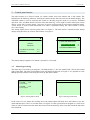
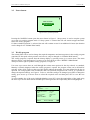
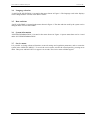
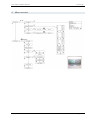
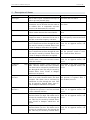
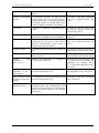
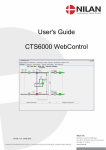
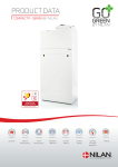
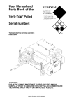
User's Guide
CTS6000 control panel
Version 1.00; 20.03.2009
Software version 1.0013
Version 1.00
User's Guide for CTS6000 control panel
1
Contents
Contents ................................................................................................................................... 2
Introduction............................................................................................................................... 2
Control panel menus................................................................................................................... 3
3.1
Alarm log/event log ............................................................................................................ 3
3.2
Power button ...................................................................................................................... 4
3.3
Weekly program ................................................................................................................. 4
3.4
Language selection.............................................................................................................. 5
3.5
Date and time ..................................................................................................................... 5
3.6
System information ............................................................................................................. 5
3.7
Service menu...................................................................................................................... 5
4 Menu overview .......................................................................................................................... 6
5 Description of alarms ................................................................................................................. 7
1
2
3
2
Introduction
The CTS6000 control panel allows functions that are necessary for everyday operation to be viewed and
altered. It is thus possible to change various temperature settings, reset alarms and start the unit outside the
usual operating period. The CTS6000 control panel supplements CTS6000 WebControl, the program in
which more advanced settings are made.
A menu overview and descriptions of all alarms can be found at the end of the guide.
Subject to alteration without notice.
NILAN A/S
Page 2 of 8
Version 1.00
User's Guide for CTS6000 control panel
3
Control panel menus
The panel consists of a "Power" button, an "Alarm" button, four arrow buttons and a "Set" button. The
buttons have the following functions. Pressing any button for the first time activates the backlit display. The
"POWER" button is used to start/stop the system in "Weekly program" mode or to activate "Extended
operation". The "ALARM" button is used to access the alarm log. "Arrow right" is used to enter/open a menu
option. "Arrow left" is used to return. "Arrow up" is used to scroll upwards or to increase a parameter setting.
"Arrow down" is used to scroll downwards or to reduce a parameter setting. The "SET" button is used to
save a new setting.
The startup display shows current system status, see Figure 1. The main menu is opened from the startup
display using the arrow up or arrow down button, see Figure 2.
GO TO MENU
MENU
LANGUAGE SELECTION
WEEKLY
PROGRAM
WEEKLY PROGRAM
SYSTEM INFORMATION
CONTROLLING SENSOR :
SETPOINT :
20.3 C
20.0 C
EXIT
EXIT
The startup display reappears if no button is pressed for 15 seconds.
3.1
Alarm log/event log
The alarm log is accessed by pressing the "ALARM" button, i.e. the one marked with a bell on the bottom
right of the panel. The most recent alarms/events will then be displayed, see Figure 3. It is possible to scroll
through previous alarms/events using the arrow up and down buttons.
ALARM LOG
ALARM LOG
No new alarms
13-03-2009
12:55
System started
13-03-2009
12:52
System stopped
Figure 3 Alarm log with new alarm
Figure 4 Alarm log with no alarms
In the event of a new alarm, the red lamp above the alarm button will flash. Press the button to view the
alarm and then press "SET" to reset the alarm, see Figure 4. If the system has been stopped as a result of an
alarm, it will be restarted once the alarm has been reset in the alarm log if the error that caused the alarm has
been remedied.
Subject to alteration without notice.
NILAN A/S
Page 3 of 8
Version 1.00
User's Guide for CTS6000 control panel
3.2
Power button
POWER
STOP SYSTEM
START EXTENDED
OPERATION
Figure 5 Power, system in operation
Pressing the "POWER" button opens the menu shown in Figure 5. "Stop system" is used to stop the system
or to start it in weekly program mode. If "Stop system" is selected the unit will remain stopped and NOT
follow the weekly program.
If "Start extended operation" is selected, the unit will continue to run for an additional 2 hours (the duration
can be changed via CTS6000 WebControl).
3.3
Weekly program
The control panel can be used to change the required temperature and start/stop times in the weekly program
(setpoints for fan speed or duct pressure can, however, only be changed via CTS6000 WebControl).
The weekly program is opened from the startup display by pressing arrow up or arrow down. The menu
shown in Figure 2 will then appear. Use arrow up or arrow down to select "WEEKLY PROGRAM"
Then press arrow right to open the weekly program, see Figure 6.
Use arrow up or arrow down to scroll through the various menu options for the day selected. As standard,
Monday is initially displayed when the weekly program is opened. Six program events can be defined for
each day of the week. Figures at the top of the display indicate the number of events defined for the day in
question. For each program event in which the unit is in operation (Program Event: Active), it is possible to
change the required settings, see Figure 6. To do so, select the setting to be changed, press SET to change the
setting, press arrow up or arrow down to select the required value and then press SET to save the new
setting.
To select another day of the week, highlight Monday, press SET, select the required day of the week using
the arrow up or arrow down buttons and then press SET again once the required day has been highlighted.
Monday
PROGRAM :
123-
PROGRAM EVENT :
TIME :
VENTILATION :
SETPOINT :
COPY TO NEXT
EXIT
Subject to alteration without notice.
ACTIVE
17:00
HIGH, STD
20.0
No
SET = CHANGE
NILAN A/S
Page 4 of 8
Version 1.00
User's Guide for CTS6000 control panel
3.4
Language selection
"LANGUAGE SELECTION" is located in the menu shown in Figure 2. The language used in the displays
can be changed under "LANGUAGE SELECTION".
3.5
Date and time
"DATE AND TIME" is located in the menu shown in Figure 2. The date and time used by the system can be
changed under "DATE AND TIME".
3.6
System information
"SYSTEM INFORMATION" is located in the menu shown in Figure 2. System status data can be viewed
under "SYSTEM INFORMATION".
3.7
Service menu
It is possible to change advanced functions, network settings and regulation parameters and to restart the
system in the "SERVICE MENU". To access the service menu, activate the control panel by pressing arrow
down. Then press and hold "SET" for approx. 10 seconds. The service menu will then appear.
Subject to alteration without notice.
NILAN A/S
Page 5 of 8
Version 1.00
User's Guide for CTS6000 control panel
4
Menu overview
Subject to alteration without notice.
NILAN A/S
Page 6 of 8
Version 1.00
User's Guide for CTS6000 control panel
5
Description of alarms
Alarm name
Description
Remedy
Door open
Door to fans is open. Ventilation unit stops in Close door and reset alarm.
order to prevent personal injury.
Fire alarm
The unit is equipped with two fire Reset fire thermostats in unit and
thermostats: one in the inlet duct, the other in reset alarm.
the exhaust duct. If temperature becomes
excessive, the thermostats are activated.
Smoke alarm
Smoke detectors can be fitted in the unit. One Check smoke detector and reset
of these smoke detectors has sensed smoke.
alarm.
Thermal relay
Motor protector has cut out; Klixon in Reset motor protector or remedy
compressor motor or fan motor has cut out; or error in frequency converter and reset
alarm.
error has occurred in frequency converter.
High pressure alarm
A high pressure alarm can be activated if Reset alarm. If the alarm repeatedly
there is insufficient air flow through the unit. occurs for no apparent reason, call
This may be caused by blocked filters, loose service.
V-belts or dampers which have not opened.
Low pressure alarm 1
Low pressure alarm 1 can be activated if The controls stop the compressor
there is insufficient air flow through the unit. until the pressure switch is reset.
This may be caused by blocked filters, loose Max. 5 times an hour, however.
V-belts or dampers which have not opened.
Low pressure alarm 2
Low pressure alarm 2 is activated if low Reset alarm. If the alarm repeatedly
pressure alarm 1 has been activated 5 times occurs for no apparent reason, call
within the last hour.
service.
Condenser
pressure
high Upper limit for cooling circuit pressure set Reset alarm. If the alarm repeatedly
under "Pressure limits" has been exceeded. occurs for no apparent reason, call
The alarm can be activated by insufficient air service.
flow through the unit. This may be caused by
blocked filters, loose V-belts or dampers
which have not opened.
Evaporator
pressure 1
low Lower limit for cooling circuit pressure, The controls stop the compressor
which is set under "Pressure limits", has been until pressure is regained. Max. 5
exceeded. The alarm can be activated by times an hour, however.
insufficient air flow through the unit. This
may be caused by blocked filters, loose Vbelts or dampers which have not opened.
Evaporator
pressure 2
low Evaporator low pressure 2 is activated if Reset alarm. If the alarm repeatedly
Evaporator low pressure 1 has been activated occurs for no apparent reason, call
5 times within the last hour.
service.
Condenser overheated
Condenser temperature setting under Reset alarm. If the alarm repeatedly
"Pressure limits" too high. The alarm can be occurs for no apparent reason, call
activated by insufficient air flow through the service.
unit. This may be caused by blocked filters,
loose V-belts or dampers which have not
opened.
Evaporator too cold
Evaporator temperature setting under Reset alarm. If the alarm repeatedly
"Pressure limits" too low. The alarm can be occurs for no apparent reason, call
activated by insufficient air flow through the service.
unit. This may be caused by blocked filters,
Subject to alteration without notice.
NILAN A/S
Page 7 of 8
Version 1.00
User's Guide for CTS6000 control panel
loose V-belts or dampers which have not
opened.
Timeout for prevention The prevention function for high or low Reset alarm. If the alarm repeatedly
function
pressure alarms has run for more than 20 occurs for no apparent reason, call
minutes but pressure is still outside the limits. service.
This may be caused by blocked filters, loose
V-belts or dampers which have not opened.
Frost alarm
Temperature of hydronic after-heating coil The controls open the water valve
too low.
and start the pump to keep the
heating coil free of ice.
Fatal frost alarm
Temperature of hydronic after-heating coil The unit is stopped. Check the afterremains too low despite prevention attempts. heating coil.
Flow alarm
Insufficient air flow across electric after- Reset alarm. If the alarm repeatedly
heating coil for coil to cut in. This may be occurs for no apparent reason, call
caused by blocked filters, loose V-belts or service.
dampers which have not opened.
Compressor starts
A compressor has started 59 times within one Set compressor minimum off time to
hour.
at least 3 minutes and reset the alarm.
VLT compressor starts A VLT compressor has started 11 times Set compressor minimum off time to
within one hour.
at least 6 minutes and reset the alarm.
Pressure
temperature
T10/11/12/13
pipe Pressure pipe temperature on compressor The controls stop the compressor and
1/2/3/4 has exceeded 125°.
do not allow it to restart before the
temperature has dropped below
50°C. If the alarm repeatedly occurs,
call service.
VLT
x
has
not A communication error has occurred between The unit stops. Reset alarm. If the
responded to the 5 the control unit and the VLTs.
alarm repeatedly occurs, call service.
latest requests
Netavent unit x has not A communication error has occurred between Reset alarm. If the alarm repeatedly
responded to the last 5 the control unit and the VLTs.
occurs, call service.
requests
T3 is set as
controlling sensor
the If a Netavent unit has been selected as the Reset alarm.
controlling sensor, but communication with
the unit concerned cannot be established, the
control unit switches instead to T3 (exhaust
temperature).
Subject to alteration without notice.
NILAN A/S
Page 8 of 8