1
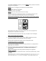
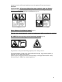
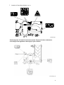
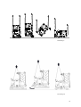
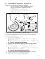
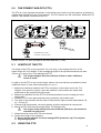
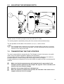
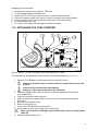
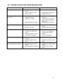
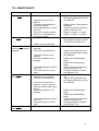
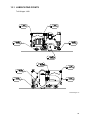
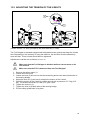
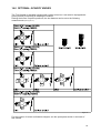
User Manual and Parts Book
Turf-Stripper
Model 1200/2000
Serial number:
Translation of the original operating instructions
ATTENTION:
IT IS OF THE UTMOST IMPORTANCE TO READ THIS USER
MANUAL CAREFULLY PRIOR TO USING THE TURF-STRIPPER IN
ORDER TO USE THE MACHINE SAFELY AND TO OBTAIN THE
BEST RESULTS.
1203 English 953.120.000
FOREWORD
Congratulations on your Turf-Stripper purchase! For safe and long-lasting operation of this
Turf-Stripper, it is necessary to read and to understand this user manual.
It is impossible to work safely with this machine without complete knowledge of its content.
The Turf-Stripper is not a machine that works independently. It is the user’s responsibility to
use the correct tractor. The user must also check the tractor/Turf-Stripper combination on
safety aspects such as noise level, user instructions and risk analysis.
The following pages deal initially with the general safety instructions. Every user should
know these safety instructions and apply them. At the end of this page, a registration card is
inserted. This registration card should be returned to enable us to deal with potential future
claims.
This user manual lists many instructions that are numbered in sequence. You should follow
this sequence. A
is an indication of a safety instruction. A
means a tip and/or note.
All information and technical specifications provided at the moment that this document is
published are the most recent ones. Design specifications may be changed without prior
notice.
This document is a translation of the original operating instructions.
Upon request, the original operating instructions are available in Dutch.
WARRANTY CONDITIONS
WITH DELIVERY THIS TURF-STRIPPER IS GUARANTEED AGAINST MATERIAL DEFECTS.
THIS WARRANTY IS VALID FOR A PERIOD OF 12 MONTHS FROM THE PURCHASE DATE.
TURF-STRIPPER WARRANTIES ARE SUBJECT TO THE ‘GENERAL CONDITIONS FOR
SUPPLY OF PLANT AND MACHINERY FOR EXPORT, NUMBER 188’ THAT ARE PUBLISHED
UNDER THE AUSPICES OF THE UNITED NATIONS ECONOMIC COMMISSION FOR EUROPE.
REGISTRATION CARD
For your own information, fill in the table below:
Serial number of the machine
Dealer name
Date of purchase
Remarks
2
SAFETY INSTRUCTIONS
Figure 1
The Turf-Stripper is designed for safe use. This
can only be achieved if you completely follow the
safety instructions described in this manual.
Read and understand (Figure 1) the manual before
you start using the Turf-Stripper.
If the machine is not used as described in this
manual, this can result in injuries and/or damage
to the Turf-Stripper.
1. The user must be an expert in using the machine. The machine should be
professionally adjusted for cultivating the subsoil.
The manufacturer will not accept any liability for unprofessional use and its resulting
damage. All risks occurring with this are entirely at the expense of the user.
Following the use, maintenance and repair instructions prescribed by the
manufacturer is also considered professional use of this machine.
Inspect the area to be treated before using the Turf-Stripper.
Remove loose obstacles and avoid irregularities.
2. The Turf-Stripper is manufactured according to the latest technical
understanding and is safe to use.
When unskilled people use, maintain or repair the machine, this could result in
injuries to the user and to third parties. This must be avoided!
Always use the Turf-Stripper in combination with the correct tractor as described in
the technical data.
3. All persons assigned to operate, maintain and repair the Turf-Stripper by the
owner must completely read and understand the operation manual and in
particular the chapter of Safety Instructions.
The user is responsible for a safe Tractor/Turf-Stripper combination. This entire
combination must be tested for noise, safety, risk and user friendliness. User
instructions should also be drafted.
4. The user is obliged to check the Turf-Stripper for visible damage and
defects before using the Turf-Stripper.
Modifications to the Turf-Stripper (including its operations) that have a negative
impact on safety must be rectified immediately.
For safety reasons it is in principle not permitted to make changes or adjustments to
the Turf-Stripper (except those approved by the manufacturer).
If modifications to the Turf-Stripper have been made, then the current CE marking
is cancelled. The person that has made these modifications has to apply for a new
CE marking himself.
Check the Turf-Stripper for loose bolts, nuts and components before every operation.
If present, check the hydraulic pipelines regularly and replace these when the
hydraulic pipelines are damaged or appear old. The pipelines that are replaced
should comply with the technical requirements of the manufacturer.
3
If a hydraulic installation is present, you should always make it pressure-free before
working on this installation.
NEVER use the Turf-Stripper in the absence of the safety stickers.
NEVER crawl under the Turf-Stripper.
If necessary, tilt the Turf-Stripper.
NEVER step off the tractor while the motor is running.
In case of maintenance, adjusting and repairs, it is necessary to block the TurfStripper in order to prevent sinking away, driving off and/or sliding off.
Always switch off the tractor motor, take the tractor’s key out off the ignition
and disconnect the PTO in case of maintenance, adjusting and repairs (Figure 2).
Figure 2
With regards to the safety of the machine and the user, use only original TurfStripper parts for maintenance and repairs.
Only authorised technical personnel may carry out repairs to the Turf-Stripper.
Keep a record of the repair activities.
5. The general applicable health & safety (Dutch: ARBO) regulations must also
be followed in addition to the instructions in this user manual.
Relevant traffic regulations also apply in case of using public roads.
Transporting persons is not permitted!
Do not use the Turf-Stripper in the dark, in heavy rain/storm or on slopes with an
angle larger than 20 degrees.
6. All persons that are going to operate the Turf-Stripper must be familiar with all
the functions and control elements of the Turf-Stripper before starting any
work activities.
Attach the Turf-Stripper to the towing vehicle according to the regulations.
(Danger of injuries!)
Check whether you have a clear field of vision – both close by and far away – before
you depart.
Safety stickers with an identical meaning are attached to the rear cover (Figure 5 and 6)
and to both sides (Figure 2, 3 and 4) of the Turf-Stripper. These safety stickers must
4
always be clearly visible and legible and must be replaced if they have become
damaged.
During operation, NO persons without the proper protection gear are allowed
within the danger zone of the Turf-Stripper, because there is danger of physical
injuries caused by flying particles or substances (Figure 3).
Figure 3
Figure 4
Keep a distance of minimum 4 metres! (Figure 4)
The rear cover must always be closed and undamaged while operating the machine!
(Figure 5)
BE CAREFUL not to get any parts of your body jammed! (Figure 6)
Figure 5
Figure 6
Pay attention to the permitted lifting capacity of the towing vehicle.
Dress appropriately. Wear sturdy shoes with steel toecaps, long trousers and tie up
long hair. Do not wear loose clothing.
Use the proper personal protection gear according to the applicable health & safety
(Dutch acronym: ARBO) and safety regulations.
5
7. Location of the safety stickers (Figure 7)
900.280.402
933.280.402
900.280.404
911.280.404
TS 2000 Fig. 7
Used oil/grease is harmful to the environment. Dispose of these substances
according to the regulations that apply in your location.
TS 1200 Fig. 7b
6
EU DECLARATION
We – Redexim BV, Utrechtseweg 127, 3702 AC Zeist, Holland – declare entirely under
our own responsibility that the product
TURF-STRIPPER WITH A MACHINE NUMBER AS INDICATED ON THE MACHINE AND
INDICATED IN THIS MANUAL
to which this declaration refers, complies with stipulation of the 2006/42/EC machine
directive.
Zeist, 26.07.11
A.C. Bos
Manager Operations & Logistics
Redexim Holland
7
TABLE OF CONTENTS
WARRANTY CONDITIONS ............................................................................ 2
REGISTRATION CARD .................................................................................. 2
SAFETY INSTRUCTIONS ............................................................................... 3
EU DECLARATION ......................................................................................... 7
1.0
TECHNICAL DATA............................................................................. 9
2.0
GENERAL DESCRIPTION ................................................................. 9
3.0
FIRST INSTALLATION – TAKING THE
MACHINE OFF THE PALLET .......................................................... 10
4.0
ATTACHING THE MACHINE TO THE TRACTOR ........................... 12
5.0
THE POWER TAKE-OFF (PTO) ...................................................... 13
5.1
LENGTH OF THE PTO..................................................................... 13
5.2
USING THE PTO .............................................................................. 13
5.3
SLIP COUPLING INFORMATION AND MAINTENANCE ................ 14
6.0
ADJUSTING THE WORKING DEPTH ............................................. 15
7.0
TRANSPORTING THE TURF-STRIPPER........................................ 15
8.0
DRIVING SPEED .............................................................................. 16
9.0
USING THE TURF-STRIPPER ......................................................... 16
10.0
START/STOP PROCEDURE ........................................................... 16
11.0
DETACHING THE TURF-STRIPPER ............................................... 17
12.0
TROUBLE SHOOTING (PROBLEM ANALYSIS) ............................ 18
13.0
MAINTENANCE................................................................................ 19
13.1
LUBRICATING POINTS ................................................................... 20
13.2
ADJUSTING THE TENSION OF THE V-BELTS .............................. 22
14.0
OPTIONAL: SCARIFY KNIVES ....................................................... 23
8
1.0
TECHNICAL DATA
2000
1200
Working width
2.0m (79”)
1,2m (49,2”)
Working depth
Working speed
Up to 50mm (2”)
The working speed depends on the
conditions and the required result. It is
maximum 3 km/h (1.8 mph).
Weight in kg
1,250 kg (2,756 lbs)
Up to 50mm (2”)
The working speed depends
on the conditions and the
required result. It is maximum
3 km/h (1.8 mph).
570 Kg (1257lbs)
Three-point connection Cat. 2
Cat 1
Gearbox oil to be used SAE 140
SAE 140
Bearing grease to be
used
Number of cutter
knives per disk
Number of disks
EP2
EP2
4
4
19
14
Recommended tractor
40 - 50 HP
30 - 40 HP
Minimum lift capacity
of the tractor
Hydraulic connections
of the tractor
PTO revs
1,450 kg (3197lbs)
775 kg (17,9lbs)
2x double-acting valves
2x double-acting valves
540 rpm
540 rpm
Standard items
PTO with slip coupling
Cutter knives
PTO with slip coupling
Cutter knives
Optional
Scarify knives
Scarify knives
2.0
GENERAL DESCRIPTION
The Turf-Stripper is a processing machine for cutting and transporting the upper layer of
ground.
9
3.0
FIRST INSTALLATION – TAKING THE MACHINE OFF THE
PALLET
The machine is placed vertically on the pallet. To remove the pallet and to place the machine
horizontally on the ground, take the following steps (see Figure 8):
NEVER crawl under the machine!
1. Attach a cable to the lifting eyes on both sides of the machine.
Make sure that the cable/crane/lift can hoist minimum twice the weight of
the machine. (See Chapter 1.0 ‘Technical Data’ for the weight details.)
2. Lift the machine including the pallet of approx. 50 mm (2”) off the ground.
3. Remove the pallet by removing the three-point pins.
NEVER crawl under the machine!
4. Slowly lower the machine until it touches the ground.
Attention: the machine can swing dangerously!
5. Attach the machine to a tractor. (See Chapter 4.0 for instructions about attaching to the
tractor.)
Use the proper tractor (please refer to the specifications).
Turn off the tractor and secure the tractor/Turf-Stripper combination
against driving off and/or sliding off.
10
TS 2000 Fig. 8
TS 1200 Fig. 8b
11
4.0
ATTACHING THE MACHINE TO THE TRACTOR
Checking procedure before starting to attach the Turf-Stripper.
− Check the Turf-Stripper for visually discernable damage and
repair this if safe operation of the machine is no longer
guaranteed.
− Check whether all the nuts and bolts are tight.
− Check whether all safety stickers are present on the machine
and are not damaged.
NEVER use the machine without these items.
Figure 9
(Shown version: TS 2000, principal is the same with the TS 1200).
The Turf-Stripper can be attached to the tractor by means of the 3-point attachment.
The procedure is as follows (Figure 9):
1. Remove the 3-point pins (1 and 2).
2. Drive the tractor carefully backwards so that the lower connecting arms can
be attached to the frame.
Make sure that the tractor is blocked well and cannot move on its own
accord!
Switch off the tractor before descending!
3. Connect the lower connecting arms to the 3-point connecting plates using the
pins (1) and secure these with the supplied locking pins.
4. Set the stabilizer of the tractor to 100 mm lateral stroke.
5. Connect the top rod (3) to the frame with the pin (2); secure the pin (2) with
the supplied locking pin.
Use Float Position 4 for towing while operating the Turf-Stripper and
Fixed Position 5 for transport!
6.
7.
8.
9.
Make sure that all the securing pins are locked!
Turn the top rod (3) until the Turf-Stripper stands horizontally on the ground.
Attach the PTO to the Turf-Stripper at the slip coupling side.
Attach the hydraulic hoses of the Turf-Stripper to the tractor.
Start the tractor and lift the Turf-Stripper off the subsoil.
12
5.0
THE POWER TAKE-OFF (PTO)
The PTO is a very important component. It also takes care of safe use of the machine, provided it is
installed and maintained in the correct manner. The PTO has its own CE certification. Read the PTO
manual. This manual is located on the PTO.
Lstandard= 33mm (1.300")
L minimum= 31.5mm (1.250")
Figure 10
(Shown version: TS 2000, principal is the same with the TS 1200).
5.1
LENGTH OF THE PTO
The length of the PTO is very important. If it is too long, it can damage the drive of the
tractor and/or the Turf-Stripper. If the overlapping length of the cylinders becomes less than
150 mm (6”) at any time, it can damage the PTO.
The length changes when the machine is lifted or when a different
tractor is used!
In order to set the PTO to the correct length, when a new one has been purchased or when
a different tractor is used, follow these steps (see Figure 9):
1. Measure the distance between the PTO’s connection to the tractor and to the TurfStripper, from groove to groove, when the machine is connected to the tractor and
positioned on the ground at the right angle.
2. Measure the distance B of the PTO in its shortest position from the locking pin to the
locking bolt.
3. Divide the PTO in two parts and remove the protection cap at both ends.
4. The ends of the cylinders and the ends of the protection caps must be made shorter: (BA) + 75 mm (3”).
5. Smooth off all components, use some grease, and then assemble all components.
6. Mount the PTO with the slip coupling at the Turf-Stripper side.
The torque of the locking bolt must be 80 Nm (700 lb.in.) and should be
checked every 40 hours.
7. Attach the other end of the PTO to the tractor.
8. Check the overlap of the cylinders.
Never use the machine if it has a damaged PTO protection cap. First replace
any damaged parts!
5.2
USING THE PTO
13
The following items must be checked for correct use of the PTO:
1.
2.
3.
4.
5.
5.3
While working the angle of the pivot pins may not exceed 30 degrees.
The pivot pins must always be aligned.
The overlap of the cylinders must always be minimum 150 mm.
Never use the machine if it has a damaged PTO protection cap.
For lubrication, please refer to Chapter 12.0 ‘Maintenance’.
SLIP COUPLING INFORMATION AND MAINTENANCE
If used and maintained correctly, the slip coupling will protect your machine against damage.
The following items are important:
1. The length of the spring is standard set at 33 mm (1.3”)
2. Whenever the slip coupling slips, the bolts/nuts can be tightened a quarter of
a turn until you achieve a minimum length of 31.5 mm (1.25”) of the spring.
Additional compression will overload the machine.
Screwing the bolts/nuts too tight could ultimately damage the machine
or create unsafe situations.
3. The slip coupling must be maintained on a monthly basis. Follow the following
steps:
- Disconnect the top PTO protection cap from the machine.
- Loosen up all the bolts/nuts by 2 turns.
- On the field let the machine run at very low revs.
- If the coupling slips, stop the motor after 10 seconds.
- If the coupling does not slip, loosen up the bolts further or proceed with
the maintenance / annual maintenance task (see point 4 below).
- As soon as the coupling has slipped, screw the bolts/nuts tight until you
see that the slip coupling is once again functioning properly.
-
Do not turn it back again to the previous setting.
4. Annual maintenance:
- Disconnect the PTO from the machine.
- Inspect all the components of the PTO.
- All the damaged components should be replaced.
- Take the slip coupling apart by removing all the bolts and nuts that
fasten the springs to each other; the slip coupling should then simply fall
apart.
- Lay down all the components and look at them meticulously. If
components are damaged or worn out, replace them.
- Clean all interlocking components.
- Re-assemble all the components and tighten the bolts and nuts so that
the springs are adjusted to 33 mm (1.3”).
- Grease both cylinders and reassemble both PTO parts.
- Assemble the PTO and mount it on the machine.
In needed, adjust the springs of the slip coupling as described below.
If adjusted properly, the slip coupling protects the machine only against
momentary overload. Long-term overload will damage the machine. In
such cases the slip coupling cannot protect the machine. Do not overload your
machine.
14
6.0
ADJUSTING THE WORKING DEPTH
Figure 11
(Shown version: TS 2000, principal is the same with the TS 1200).
The working depth is adjusted by setting the front and rear rollers simultaneously.
The two spindles at both sides of the machine (see Figure 11) set the rollers.
If the transport belt is folded out, the machine weight shifts to this side. As a result,
more material can be removed at this side. You can compensate this by setting the
machine not so deep at this side.
7.0
TRANSPORTING THE TURF-STRIPPER
The user is responsible for transporting the Turf-Stripper in back of the tractor over public
roads. Verify the national legislation regarding the regulations.
On open fields while the machine is raised and if circumstances allow this, the maximum
permitted speed is 12 km/h (8 mph) due to the weight of the Turf-Stripper.
A higher speed can be dangerous for the driver and/or the public and can even damage the
machine.
Make sure that the uppermost top rod is attached and is pressurized in the
transport position (position 5)! See Chapter 4.0, figure 9. If this is not done, the
machine can incur serious damage.
Attention: the transport belt has to be tipped up!
When the machine is raised off the ground, the front axle of the tractor has to
support minimum 20% of its weight.
15
8.0
DRIVING SPEED
The driving speed depends on the conditions and the required result. It is maximum 3 km/h
(1.8 mph).
It is NOT recommended to drive faster due to the fact that excessive wear & tear and
damage can occur to the machine and to the subsoil.
9.0
USING THE TURF-STRIPPER
Before using the Turf-Stripper in a location, you should check the following items:
1.
2.
3.
4.
5.
6.
7.
Are there loose objects in the field? First remove these objects.
Are there slopes? The maximum slope is 20 degrees for this machine.
Always go from top to bottom.
Is there danger of flying objects (e.g., balls) that distract the attention
of the driver? If so, the Turf-Stripper CANNOT be used.
Is there danger of sinking/sliding away? If so, postpone the processing
until conditions improve.
Are there hard objects in the ground? If so, use the Turf-Stripper with a
low PTO speed and adjust the working depth.
If the soil is very wet, postpone the activities until conditions improve.
10.0 START/STOP PROCEDURE
The start procedure is VERY important. If this procedure is not executed as described below,
it might result in serious damage to the machine.
The start procedure is as follows:
1. Check the Turf-Stripper for loose components and look whether all components
function properly.
If loose components are observed or components do not function properly,
the problems must be solved before using the Turf-Stripper!
2. Drive to the spot where the processing should take place.
Attention: the transport belt has to be tipped up!
3. Lower the machine onto the ground.
4. Fold the transport belt out by activating the hydraulic outlet of the tractor.
Make sure that the tractor is blocked well and cannot move on its own
accord!
Switch off the tractor before descending!
5. Adjust the working depth as described in Chapter 6.0.
6. If required, the top rod can be placed in the slotted hole (4) in the towing position
(see Chapter 4.0, figure 9).
7. Raise the Turf-Stripper slightly so that the knives just don’t touch the ground and
engage the tractor in the proper gear.
8. Activate the hydraulic outlet of the tractor in order to let the transport belts turn.
9. Adjust the tractor engine to around 1200 rpm and switch on the PTO.
10. Slowly lower the machine until it reaches the required working depth.
11. Drive forwards and increase the rotational speed until the PTO rotational speed of
540 rpm is achieved.
12. For the first track:
Check whether the required working depth is achieved. If necessary, adjust the working
depth as described in Chapter 6.0.
16
Stopping occurs as follows:
1.
2.
3.
4.
5.
6.
7.
Decrease the engine revs to approx. 1200 rpm.
Lift the machine slightly off the ground.
Switch the PTO off as soon as the knives no longer touch the subsoil.
Close the hydraulic outlet of the tractor (used for operating the transport belts).
Fold the transport belt in by activating the hydraulic outlet of the tractor.
Lift the machine even more.
Go to the next location and start again as described above.
11.0 DETACHING THE TURF-STRIPPER
Figure 12
(Shown version: TS 2000, principal is the same with the TS 1200).
The machine can be detached from the tractor in the following manner (See Figure 12):
1. Drive the Turf-Stripper to a parking area with a firm/flat surface.
Make sure that the tractor is blocked well and cannot move on its own
accord!
Switch off the tractor before descending!
Attention: the transport belt has to be tipped up!
2. Adjust the height of the rollers so that the machine stands above the ground
(see Chapter 6.0).
3. Lower the machine onto the ground.
4. Make sure that the machine cannot move on its own accord by blocking the
rear roller.
5. Remove the hydraulic hoses.
6. Remove the top rod (3).
7. Loosen the PTO at the side of the tractor.
8. Disconnect the lower connecting arms of the tractor.
Make sure that the Turf-Stripper stands stable and cannot roll away and/or
slide off!
9. Start the tractor and drive off.
17
12.0 TROUBLE SHOOTING (PROBLEM ANALYSIS)
Problem
Machine vibrates.
Possible cause
Solution
Obstacle(s) between the
knives
Worn or broken knives.
Rotor is bent.
-
Remove the obstacle(s).
-
Replace with new knives.
Replace the rotor.
-
-
Working depth is not
adjusted correctly.
Subsoil is too hard.
-
-
Driving speed is too high.
-
Adjust the working depth
properly.
Lower the driving speed or
pass over the soil more
than once.
Lower the driving speed.
Too coarse processing of the soil
-
Driving speed is too high.
-
Subsoil is too wet.
-
Subsoil is too wet.
Obstacle(s) between the
knives
Driving speed is too high.
Too much overgrowth
-
-
Working depth is not
achieved.
Rotor is jammed.
-
-
Rotor does not turn.
-
Transport belt cannot cope
with the quantity of material.
-
The V-belts that drive the
rotor slip.
Machine is adjusted too
deep.
Driving speed is too high.
Transport belt turns too
slowly.
Working depth is too deep.
Decrease the driving
speed.
Wait for better conditions.
-
Wait for better conditions.
Remove the obstacle(s).
Decrease the driving
speed.
Cut the overgrowth.
-
Pull the V-belts taut.
-
Adjust the machine to less
depth.
Lower the driving speed.
Increase the oil flow of the
tractor.
Decrease the working
depth.
-
18
13.0 MAINTENANCE
Time schedule
Check/Grease point
Before every use
-
Check for loose bolts/nuts.
-
-
-
-
Check the oil level in the
gearbox.
Presence and readability of
the safety stickers
Loose hanging parts around
the PTO
Check for hydraulic defects.
Check for cracks/defects in
the transport belts.
Clean the machine.
-
Grease the rotor bearings.
After the first 20
working hours (new or
repaired)
After every use
-
Method
-
After every 50
working hours
-
-
Lubricate the PTO and
bearings.
Check for loose bolts/nuts.
-
Use EP2 grease
-
Check the oil level in the
gearbox.
Check the gearbox for oil
leakage.
-
Tighten loose bolts/nuts with
the correct tightening moment.
Use SAE140.
-
Loose hanging parts around
the PTO
Check the tension of the Vbelts.
Lubricate the PTO and
bearings of the machine.
Check for loose bolts/nuts.
Check the oil level in the
gearbox. It has to reach at
least the halfway mark of the
gauge.
Check the gearbox for oil
leakage.
-
-
-
After every 500
working hours
-
Replace these if not present or
damaged.
Tighten the parts so that they
cannot reach the PTO.
Repair or replace, if needed.
Repair or replace, if needed.
Watch out for the bearings if a
high-pressure sprayer is used.
1 shot EP2 (see Figure13)
-
-
Tighten loose bolts/nuts with
the correct tightening moment.
Use SAE140.
Loose hanging parts around
the PTO
Check the tension of the Vbelts.
Change the oil in the gearbox.
-
Repair the leaks/damaged
parts.
Replace the seals/sealing
paste.
Tighten the parts so that they
cannot reach the PTO.
If needed, adjust the tension
(see Section 13.2).
Use EP2 grease (see Figure
13)
Tighten loose bolts/nuts with
the correct tightening moment.
Use SAE140.
Repair the leaks/damaged
parts.
Replace the seals/sealing
paste.
Tighten the parts so that they
cannot reach the PTO.
If needed, adjust the tension
(see Section 13.2).
Use SAE140.
19
13.1 LUBRICATING POINTS
Turf-Stripper 1200
TS 2000 Figure 13
20
Turf-Stripper 1200
TS 1200 Fig. 13b
21
13.2 ADJUSTING THE TENSION OF THE V-BELTS
Figure 14
(Shown version: TS 2000, principal is the same with the TS 1200).
The Turf-Stripper is standard equipped with adjustable tension pulleys that keep the V-belts
taut. Depending on the intensity of using the machine, the driveline could be affected by
wear and tear. These V-belts should then be tightened.
Adjustment is carried out as follows (see Figure 14):
Make sure that the Turf-Stripper is blocked well and cannot move on its
own accord!
Make sure that the PTO is detached from the Turf-Stripper!
1. Remove the safety guard (1).
2. Loosen the lock nut (3).
3. Loosen the nuts (2) one turn so that the tensioning device can rotate (both sides of
the bearing bridge).
4. Adjust the lock nut (3) and use it to adjust the tension of the V-belts.
5. Check the tension of the V-belt by pushing point A with a pressure of 7.5 kg (16.5
lbs). The stretch should be 12.4 mm (0.5”) per V-belt.
6. Tighten the lock nut (3).
7. Tighten the nuts (2) at both sides of the bearing bridge.
8. Put the safety guard back in its place.
22
14.0 OPTIONAL: SCARIFY KNIVES
The Turf-Stripper is standard equipped with cutting knives but it can also be equipped with
Scarify knives (if required) for aerating the subsoil.
Placing the knives in specific positions, the slot distance can be set to the following
measurements (see Figure 15):
Figure 15
For the number of knives and balance weights, see the spare parts section in the back of
this manual.
23