1
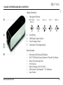
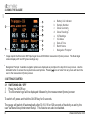
en
R
User Guide
Elcometer 408
Gloss & DOI Meter
CONTENTS
1
Gauge Overview and Box Contents
6
Batching
2
Using the Gauge
7
Menu Structure
3
Getting Started
8
Downloading Data
4
Calibrating the Gauge
9
Additional Information
5
Taking a Reading
10 Glossary
www.elcometer.com
en
R
Pb
Hg
These operating instructions are a short User Guide only. For the avoidance of doubt, please refer to the original English language version.
The Elcometer 408 meets the Radio and Telecommunications Terminal Equipment Directive. This product is Class B, Group 1 ISM equipment
according to CISPR 11. Class B product: Suitable for use in domestic establishments and in establishments directly connected to a low voltage
power supply network which supplies buildings used for domestic purposes. Group 1 ISM product: A product in which there is intentionally
generated and/or used conductively coupled radio-frequency energy which is necessary for the internal functioning of the equipment itself.
This device complies with Part 15 of the FCC Rules. Operation is subject to the following two conditions: (1) this device may not cause harmful
interference, and (2) this device must accept any interference received, including interference that may cause undesired operation. This device
complies with Part 15 of the FCC Rules. Operation is subject to the following two conditions: (1) this device may not cause harmful interference,
and (2) this device must accept any interference received, including interference that may cause undesired operation.
NOTE: This equipment has been tested and found to comply with the limits for a Class B digital device, pursuant to Part 15 of the FCC Rules. These limits are
designed to provide reasonable protection against harmful interference in a residential installation. This equipment generates, uses and can radiate radio
frequency energy and, if not installed and used in accordance with the instructions, may cause harmful interference to radio communications. However, there is
no guarantee that interference will not occur in a particular installation. If this equipment does cause harmful interference to radio or television reception, which
can be determined by turning the equipment off and on, the user is encouraged to try to correct the interference by one or more of the following measures:
– Reorient or relocate the receiving antenna.
– Increase the separation between the equipment and receiver.
– Connect the equipment into an outlet on a circuit different from that to which the receiver is connected.
– Consult the dealer or an experienced radio/TV technician for help.
Modifications not expressly approved by Elcometer Limited could void the user's authority to operate the equipment under FCC rules.
is a registered trademark of Elcometer Limited, Edge Lane, Manchester, M43 6BU. United Kingdom
are trademarks owned by Bluetooth SIG Inc and licensed to Elcometer Limited. Bluetooth SIG QDID = B014393
All other trademarks acknowledged.
R
Gauge dimensions: 65 x 140 x 50mm (2.56 x 5.51 x 1.97")
Gauge Weight: 790g (1.7lb)
© Elcometer Limited 2012. All rights reserved. No part of this document may be reproduced, transmitted, transcribed, stored (in a retrieval system or otherwise)
or translated into any language, in any form or by any means (electronic, mechanical, magnetic, optical, manual or otherwise) without the prior written
permission of Elcometer Limited.
TMA-0551 Issue 02 - Text with cover 23523
R
en
1 GAUGE OVERVIEW AND BOX CONTENTS
Gauge Overview
1
1
2
3
Navigation Buttons
Select / Enter /
Measure
2
3
4
5
Up (5)
Down (6)
Left (3)
Right (4)
On/Off Key
USB Data Output Socket
Fast Charge Socket
Calibration Tile (Magnetised)
4
Box Contents
5
www.elcometer.com
§
§
§
§
§
§
§
Elcometer 408 Gloss & DOI Meter
ISO 17025 High Gloss Calibration Tile with Certificate
Gloss Tile Cleaning Cloth
Transit Case
Mains Charger (UK, EU & US)
USB Cable & ElcoMaster™ 2.0 Software
User Guide
2
R
en
2 USING THE GAUGE
a
i
b
c
d
e
f
g
h
a
b
a
b
c
d
e
f
g
h
i
Battery Life Indicator
Sample Number
Gloss Geometry
a
Gloss Readings
IQ Readings
IQ Values
Date & Time
Batch Name
b
Navigation Prompts
Image depicts the Elcometer 408 Triple Angle Gloss & DOI Meter measurement (home) screen. The Dual Angle
version displays 20° and 60° gloss readings only.
Navigation Prompts: Available navigation options are displayed as prompts on the top left of every screen. Use the
indicated button to access the required menus and options. Pressing
once or twice from any menu will return the
user to the measurement (home) screen.
3 GETTING STARTED
3.1 SWITCHING ON / OFF
1
2
Press the On/Off key
The Elcometer logo will be displayed followed by the measurement (home) screen
To switch off, press and hold the On/Off key for 3 seconds.
The gauge will switch off automatically after 30, 60, 90 or 120 seconds of inactivity as set by the
user via Menu/Setup/Instrument Setup. This feature can also be disabled.
3
www.elcometer.com
R
1
2
3
en
3 GETTING STARTED (CONTINUED)
3.2 SELECTING THE LANGUAGE
Select Menu/Setup/Instrument Setup
Press the or
navigation button to highlight “Language”
Press the navigation button to scroll through the available languages until the required
language is displayed.
3.3 SETTING THE DATE AND TIME
1
2
3
Select Menu/Setup/Instrument Setup
Press the or
navigation button to highlight “Set Date & Time” followed by
to select
Press the navigation button and adjust the date and time following the on screen prompts.
3.4 SETTING THE MEASUREMENT PARAMETERS
The Elcometer 408 is available in two models; a Triple Angle (20°, 60° & 85°) or Dual Angle (20°
and 60°) Gloss and DOI Meter. The gauge measures gloss# and IQ (Image Quality) values# (DOI,
RIQ, Haze or logHaze and RSpec).
Via Menu/Setup/Measurement Menu users can select which measurement values are displayed:
Geometry: Display gloss readings at 1, 2 or 3† gloss angles
Range:
Select AUTO (full scale) or BLACK (standard gloss scale)
Haze:
Select Haze# or logHaze#
DOI:
Select DOI# (Distinctness of Image) or enhanced RIQ# (Reflected Image Quality) scale
IQ:
Switch ON / OFF IQ values#. When switched OFF, only gloss readings are displayed on screen.
#
†
For an explanation of terms, refer to the Glossary on page 13.
Elcometer 408 triple angle version only
www.elcometer.com
4
R
en
4 CALIBRATING THE GAUGE
The gauge has an automatic calibration option which detects when the Elcometer 408 calibration tile is
in position. This is switched ON by default but can be disabled via Menu/Setup/Calibration Menu.
The gauge is supplied with filter paper protecting the calibration tile. This must be removed before
calibrating.
4.1 CALIBRATING WHEN AUTOMATIC CALIBRATION IS ENABLED
1
Place the gauge on the calibration tile and press the
navigation button. The following
message will be displayed:
“Tile Detected - Assigned Values; 20° - xx.x; 60° - xx.x; 85° - xx.x†”.
Note: The calibration values of the tile supplied with the Elcometer 408 are pre-programmed into the gauge. If
using a different tile, follow the procedure outlined in Section 4.3.
2
3
Press the or
Press the or
the calibration
navigation button to highlight “CALIBRATE" followed by to select
navigation button to highlight “CONFIRM" followed by to select and save
4.2 CALIBRATING WHEN AUTOMATIC CALIBRATION IS DISABLED
1
2
Place the gauge on the calibration tile and select Menu/Calibrate Instrument
Press the or
navigation button to highlight “CONFIRM" followed by to select and save
the calibration
Note: The calibration values of the tile supplied with the Elcometer 408 are pre-programmed into the gauge. If
using a different tile, follow the procedure outlined in Section 4.3.
†
5
Elcometer 408 triple angle version only
www.elcometer.com
R
en
4 CALIBRATING THE GAUGE (CONTINUED)
4.3 CALIBRATING WHEN USING DIFFERENT CALIBRATION TILES
If using a different tile to the one identified by the Elcometer 408, the calibration values of the tile
must be manually entered, before performing the calibration procedure.
1
2
3
4
Select Menu/Setup/Calibration Menu
Press the or
navigation button to highlight “Tile Value 20" followed by
Follow the on screen instructions to set the tile value
Repeat for “Tile Value 60" and “Tile Value 85†"
to select
The gauge has an automatic error detection feature which checks for contamination or damage to
the calibration tile.
To assess the condition of the tile the gauge measures the HAZE value of the tile. A clean
undamaged calibration tile will always measure <0.1 HU.
The automatic error detection can be disabled or adjusted via Menu/Setup/Calibration Menu. This
allows mid-gloss calibration tiles with haze to be used for calibration.
†
Elcometer 408 triple angle version only
www.elcometer.com
6
R
en
5 TAKING A READING
1
2
Place the gauge on the substrate and press the
navigation button
The reading is taken and the measurement data updated
The gauge can be set to take automatic readings at 2, 5 or 10 second
intervals. This feature can be enabled via Menu/Setup/Measurement
Menu/Auto Measure.
Pressing the navigation button will access the graph screen; this displays
the goniophotometric profile for the last reading. Readings can still be taken
with the graph displayed - which will be updated automatically.
Pressing the navigation button will access the gloss statistics screen,
displaying statistics for the current batch. Readings can also be taken in this
screen and the statistics will be updated accordingly.
Pressing the navigation button in the gloss statistics screen will access the
IQ (image Quality) statistics screen (DOI, logHaze & Rspec).
Pressing the navigation button in the gloss statistics screen will access the
gloss graph; this gives a graphical representation of the gloss measurements.
Pressing the navigation button in the gloss graph screen accesses the IQ
graph screen. Readings can be taken in this screen, the graph will update after
each reading.
Note: Graphs will only be displayed when two or more measurements have been taken.
7
www.elcometer.com
R
en
6 BATCHING
All Batch functions are accessed via Menu/Setup/Data & Batch Menu. Limited Batch functions are
also displayed on the initial Menu screen.
Batch functions are only available when Memory is switched ON (Menu/Memory).
6.1 CREATING BATCHES
1
2
3
Select Menu or Menu/Setup/Data & Batch Menu
Press the or
navigation button to highlight “Start New Batch” followed by
to select
Readings are automatically stored in the open batch until a new batch is created.
Batches are named “BATCH.xxn” by default, where “xxn” is incremented for each new batch created.
“BATCH” can be changed to a user defined name by connecting to a PC - see Section 6.3.
Statistics for the current batch can be viewed by pressing the navigation button whilst in the
measurement (home) screen. A trend graph of the individual gloss values can also be viewed by
pressing
again.
Menu/Clear Current Batch deletes all readings from the open batch.
Menu/Delete All Batches deletes all readings from all batches stored in the memory.
www.elcometer.com
8
R
en
6 BATCHING (CONTINUED)
6.2 AUTO BATCHING
“Auto Batch” allows users to pre-define the number of readings to be stored in a batch before a new
batch is opened automatically.
1
2
3
4
5
Select Menu/Setup/Data & Batch Menu
Press the or
navigation button to highlight “Auto Batch”
Press the navigation button to toggle ON
Press the navigation button to highlight “Batch Size” followed by
Adjust the batch size following the on screen prompts
to select
6.3 VIEWING BATCH DATA
1
2
Connect the instrument to a PC using the USB cable supplied
Double click on the USB data folder “IQ Meter”. This can be accessed in Windows via “MY
COMPUTER”, within this file open the DATA folder. Within this folder are subfolders containing
the data for each individual saved batch. Each reading is saved as an individual .csv file
containing Gloss, Haze, DOI/RIQ, RSpec, Time and Date of Reading, Serial Number and Full
Goniophotometric data for all 512 diode elements. Each reading also contains the statistics for
the batch up to and including that reading. To access the STATISTICS for the whole batch, the
last reading in the batch should be examined.
9
www.elcometer.com
R
6.4 CREATING USER DEFINED BATCH NAMES
1
2
3
4
5
Connect the instrument to a PC using the USB cable supplied
Double click on the USB data folder “IQ Meter”. This can be accessed in Windows via “MY
COMPUTER”, within this file open CONFIG>Batches. This document is a .csv file and can be
opened/edited in programs such as Notepad, Excel or Wordpad. User defined names should
entered into this document with each name listed on a separate line. The batch name length is
limited to 8 letters or numbers, further characters are not included the description.
Switch OFF and ON to transfer the new batch names to the gauge
Select Menu/Setup/Data and Batch Menu
Press the or
navigation button to highlight “Batch Name” followed by to select the
required name from those stored in the gauge
www.elcometer.com
10
en
6 BATCHING (CONTINUED)
R
en
7 MENU STRUCTURE
Menu
SETUP
Memory: ON (xx.x%free)
Delete Last Reading
Start New Batch
Clear Current Batch
Delete All Batches
Batch Name
:xxxxx
Calibrate Instrument
Switch Off
Calibration
BLACK, MIRROR
Control
RC: not currently used
DATA: transmits on screen
parameters
DATA+: transmits all
goniophotometric data
Calibration
Calibrate Instrument
Auto Calibration : ON/OFF
Calibrate to
:xxxxx
Tile Value 20
:xx.x
Tile Value 60
:xx.x
Tile Value 85
:xx.x
Error Detection :ON/OFF
Haze Tolerance :x.x
Control
Enable Remote Control
Bluetooth‡
:ON/OFF
Bluetooth Mode‡ :xxxxx
Maintenance
Enter PIN Code
(This menu option is for
Elcometer use only)
‡
Setup
Data & Batch Menu
Calibration Menu
Measurement Menu
Control Menu
Instrument Setup
Factory Menu
About
Data
Memory: ON/OFF(xx% free)
Delete Last Reading
Start New Batch
Clear Current Batch
Delete All Batches
Auto Batch
:ON/OFF
Batch Size
:x
Batch Name
:xxxxx
Measurement
Auto Measure :xxxxx
Range
:xxxxx
IQ
:ON/OFF
DOI
:xxx
Haze
:xx.x
Geometry
:xx.x
Instrument Setup
Language
:xxxxx
Screen View
:xxxxx
Backlight
:xxx%
Power Off
:xxxxx
Power Switch :xxxxx
Sound
:ON/OFF
USB Charge
:xxxxx
Set Date & Time
About
Serial Number
Firmware Version
Scanner Version
Factory Calibration
Memory Free
Battery Voltage
USB Charge
Measurement
OFF, 2 sec, 5 sec, 10 sec
AUTO, BLACK, MIRROR
DOI, RIQ
Haze, logHaze
20, 60, 85, 20/60, 20/60/85
Instrument Setup
NORMAL, INVERTED
20%, 40%, 60%, 80%, 100%
DISABLED, 30 sec, 60 sec, 90 sec, 120 sec
ON & OFF, ON ONLY
500mA, 100/500mA
:xxxxxxx
:x.xx
:xxxxxx
:xxxx-xx-xx
:xx%
:x.xxV
:xxxxx
Bluetooth not currently available in Japan
11
www.elcometer.com
R
en
8 DOWNLOADING DATA
Using ElcoMaster™ 2.0 - supplied with the gauge and available as a free download at
www.elcometer.com - batch data can be transferred via USB to a PC for archiving and report
generation.
9 ADDITIONAL INFORMATION
Gloss
Haze
DOI
Resolution
0.1 GU
0.1 HU
0.1
Repeatability
0.2 GU
0.2 HU
0.2
Reproducibility
0.5 GU
0.5 HU
0.5
RSPEC
Peak Specular Reflectance at 20°: ±0.09375°
Power
USB rechargeable in 4.5 hours; mains rechargeable in 2.5 hours
Battery Life
>17hrs continuous operation or 20,000 readings
Memory
>999 readings with full goniophotometric profiles
Gauge Dimensions
65 x 140 x 50mm
(2.56 x 5.51 x 1.97")
hxwxd
Gauge Weight
790g (1.7lb)
Can be used in accordance with:
ASTM D523, ASTM D2457, ASTM D5767, ASTM E430, DIN 67530, ISO 2813, ISO 13803, JIS 8741
www.elcometer.com
12
R
en
10 GLOSSARY
10.1 GLOSS
Gloss is the visual sensation associated with the brightness of direct light reflected in a surface. Surfaces
with high reflectance are determined as glossy; less reflective surfaces are semi-gloss or matt. Glossmeters
quantify this effect by measuring light reflection from a sample at defined angles.
The measurement angles most commonly used for gloss are 20°, 60° and 85°. The most appropriate angle
should be selected dependent on the glossiness of the sample surface. Using the correct measurement
geometry increases resolution and improves the correlation of results with human perception of quality .
To determine the correct measurement angle the surface should be assessed with the 60° geometry:
- Matt surfaces which measure below 10 GU at 60° should be re-measured with the 85° angle.
- High gloss surfaces which measure above 70 GU at 60° should be assessed using the 20° angle.
The 60 degree angle is best employed on mid gloss samples measuring between 10 and 70 GU.
10.2 HAZE
Haze describes the milky halo or bloom seen on the surface of high gloss finishes. It is caused by
microscopic surface texture which diffuses light adjacent to the main component of the reflected light.
Surface haze can be problematic in most coating applications including automotive manufacture, powder
coatings and other high gloss coatings. It can be attributed to a number of causes including incompatible
materials in a formulation, poor dispersion and problems encountered during drying/curing/stoving.
Coatings without haze can be seen to have a deep reflection and have high reflected contrast. Those with
haze exhibit a slight “milky” finish which can be seen over the highly glossy surface.
13
www.elcometer.com
R
Gloss-haze meters are traditionally used to measure this parameter however , taking reliable readings on a
tradition gloss-haze meter can be difficult as the sample surface needs to be completely flat and un-textured.
The Elcometer 408 automatically compensates for sample surface flatness and texturing allowing haze
measurements to be taken on a much wider range of product surfaces.
Gloss Haze values are calculated using the angular tolerances described in ASTM E430. The Elcometer 408
can display the natural haze value (HU) or Log Haze Value (HULOG).
When measuring haze values, higher numbers indicate a lower quality surface. A high gloss surface with
zero haze has a deep reflection image with high contrast.
Log Haze Values are commonly quoted for paints and coatings as this scale has better corroboration with
human perception of surface quality.
10.3 DOI (DISTINCTNESS OF IMAGE)
Distinctness of Image is a measure of the sharpness of a reflected image in a coating surface.
Two surfaces finished with similar coatings may exhibit identical gloss values but visually the quality of one
coating can be seen to be very poor. Upon closer inspection the visually substandard poor coating has a
highly textured dimpled appearance known as “orange peel”. When a reflected object is viewed in such a
coating the image becomes fuzzy and distorted.
Orange peel, waviness, texturing, pin holing and similar ef fects can be problematic in many high gloss
coating applications including automotive, powder coating and any other industries that require a smooth
homogenous finish. All these effects can be measured with the Elcometer 408.
The Elcometer 408 measures the DOI of a surface by quantifying the way a reflected measurement beam is
spread and distorted around the specular angle.
www.elcometer.com
14
en
10 GLOSSARY (CONTINUED)
R
en
10 GLOSSARY (CONTINUED)
The DOI value is expressed as a number between zero and one hundred; a surface that exhibits a perfect
undistorted image returns a value of 100, the values decrease and as the image becomes less discernable.
10.4 RIQ (REFLECTED IMAGE QUALITY)
Reflected Image Quality provides greater sensitivity when evaluating highly reflective coatings and the
specular / diffuse element of lower gloss materials.
Two highly reflective surfaces that have very small changes in orange peel or texture will show very little or
no change in DOI due to the way that it is calculated, but will appear quite dif ferent visually. By reducing the
sensing distance around the specular angle and measuring the reflected light and distortion around it, a
much higher resolution response is achieved with greater linearity, more in line with the visual experience.
Similarly for lower gloss materials, due to the smaller sensing distance, this measurement allows improved
differentiation of the specular and diffuse elements of reflectance from the surface. As this sensing distance
only allows the measurement of the amount of truly reflected light in the specular direction it is far more
directionally selective. However when using RIQ a greater dif ferentiation is achieved.
The RIQ value of a surface is also a number between zero and one hundred; a surface that exhibits a perfect
undistorted image returns a value of 100, as the values decrease higher surface texture is present and the
image sharpness reduced.
10.5 RSPEC (PEAK SPECULAR REFLECTANCE)
Rspec is the peak reflectance measured over a very narrow angle in the specular direction ±0.9375º.
Rspec is very sensitive to any surface texture. Waviness or rippling on a surface acts as a concave or
convex reflector deflecting light around the specular angle. When Rspec is equal to the gloss the surface is
smooth. RSpec drops as texture becomes apparent.
15
www.elcometer.com