1
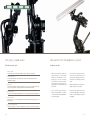
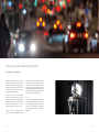
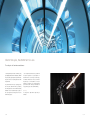
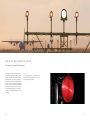
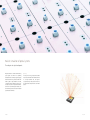
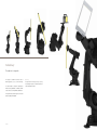
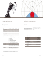
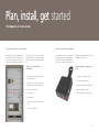
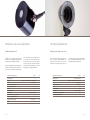
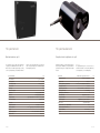
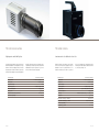
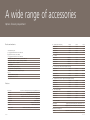
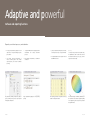
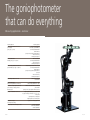
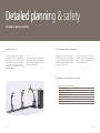
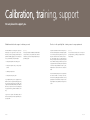
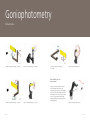
robogonio Quick. Precise. Highly flexible. www.robogonio.com One system, six good reasons Measurements with the robogonio at a glance What the robogonio can do. Everything is possible. 1.Highest flexibility Goniophotometry in near and far field, various detector systems – combined in one instrument. • 2. Extremely quick scans The class L photometer reduces the measurement time. This means for example: Hemisphere within approximately two minutes. 3. Variable sizes The robogonio is available in seven basic variants (payloads of 6, 10, 16, 30, 60, 120, 240 kg), special models of up to 1,000 kg are possible. Our experienced partner for robotics: KUKA Roboter GmbH. 4. Maximum precision The robogonio offers the highest angle repeatabilities of 0.005° along with a photometer of the highest class (L). 5. Intuitive operation • With its six axes, the robogonio combines s everal goniophotometer types in a single instrument (DIN EN 5032-1, DIN EN 13032-1, CIE 121). Especially types 1.1, 1.2, and 1.3 are dead easy for the robogonio. In these types, the detector is stationary while the test piece (light source, luminaire, display…) rotates around its vertical and horizontal axes. • In the near field, the robogonio generates ray data of light sources with high precision, and even p olychromatic depending on the detector. Far-field data can be calculated directly from the ray data. • Angular dependent luminance measurements, for example, form the basis for glare ratings. In the far field, the robogonio measures the luminous intensity distributions of luminaires. Conventional far-field data such as EULUMDAT or IES are generated directly. • Mounted on the robot arm, the detector can scan any geometry, including planes. This allows a quick evaluation of the light distribution of luminaires and headlights. The robogonio is easy to use. Complicated and error-prone measurements with mirror goniophotometers are a thing of the past. 6. All-round carefree package We are pleased to support you – from the complete planning of your system to competent after-sales support. 2 of 36 3 of 36 Safety & innovation under high time pressure The robogonio for automotive. In the automotive industry, two aspects of photometric measurement are of particular importance: Firstly, the demand for extremely quick and authoritative results. Secondly, the possibility to effect the measurements with the finest angular resolutions so that the tests comply with the applicable standards. The robogonio meets both of these requirements perfectly. The high-speed photometer reduces the time required for classic goniometric measurements in the HV system (ECE, SAE) to a few minutes. Also, the robogonio permits angular resolutions of 0.01°. This enables the precise observance of the cut-off line. But that's not all: Due to its spatial flexibility, the robogonio can cover different headlight functions such 4 of 36 as high beam, low beam, or direction indicators around different centres of rotation in a single measuring run. To this purpose, the robogonio supplies the headlight directly via an optional 13-channel mounting adapter, either through the integrated power supplies or through BUS signals. All measuring points according to ECE and SAE are scanned by the system automatically. By the way For measuring elongated light guides, the robogonio can be equipped with a high-resolution camera. Instead of doing complicated measurements in individual steps, the robogonio scans the light guide and conveniently provides high-precision results on the luminance distribution. 5 of 36 Shorter F&E cycles, EULUMDAT & IES in view The robogonio for luminaire manufacturers. Constantly launching new variants of luminaires, easily providing light planners with far-field data (IES, EULUMDAT), and quickly generating the required LED data. robogonio stands for a measuring solution that fulfils all requirements. First, the luminaire warms up in operating position; the run-up curve (DIN EN 13032-4) is provided by the auxiliary photometer. Then the luminous intensity distribution can be measured through any angle in the C-plane system since the robogonio can move the luminaire freely in space. 6 of 36 Color-over-angle measurements are also possible with the optional spectrometer. So optics designers can determine how the color changes at certain angles, and whether unwanted color effects occur. Another important topic is the measurement of the total luminous flux in relation to the consumed electrical power. Luminous flux efficiency in lumen/watt and energy efficiency classes can be determined directly. By the way The robogonio also helps with the glare rating of luminaires. 7 of 36 Light on the spot, reliable and accurate The robogonio for signal light manufacturers. For measuring traffic lights, railway signals, beacons, or signal towers for production, the luminous intensity distribution is essential. Some applications present the additional challenge of the front and back light exit windows having to emit the exact required quantity of light. Here, the robogonio impresses with its flexibility since it can measure the luminous intensity distribution in both directions using arbitrary centres of rotation in space. Standard-relevant testing areas, for example according to ICAO, FAA, and DIN EN 12368, are covered automatically. 8 of 36 By the way For fast and efficient work, the robogonio enables integrating user-defined measuring processes as well as the numerous updates of standards. 9 of 36 Realistic simulation of optical systems The robogonio for optics development. All lights are different – a dilemma with which many optics designers are familiar in the preliminary development. At the same time, the systems are getting smaller and smaller – the key word here is LEDs. When reliable ray data for optical simulations are needed, conventional solutions are limited. The robogonio measures light sources with a high-resolution luminance camera from 10,000 different angles. This leads to reliable near-field ray data that can be used in all standard optics simulation environments. 10 of 36 By the way The robogonio is the only goniophotometer available that can do actual far-field and near-field m easurements in one single instrument. Thus, the robogonio accompanies developers and producers from the first idea throughout the development and to the finished product. 11 of 36 Evolutionary The right size for every task. The robogonio is available in seven basic sizes for different payloads (6, 10, 16, 30, 60, 120 and 240 kg). The smaller models are designed for measuring the luminous intensity distribution of luminaires and LED PCBs as well as for scanning illuminance distributions. By the way The sky's the limit – almost. Payload of up to 1,000 kg are possible upon request. Our experienced partner for robotics: KUKA Roboter GmbH. The larger models are suitable for systems such as street lights, stage lights, and headlights. 12 of 36 13 of 36 The right model for every case Configured as per your requirements The robogonio - overview. Detectors & co. Type Maximum payload * [kg] Weight [kg] Work envelope radius [mm] approx. Position repeatability [mm] mrg-6 mrg-10 mrg-16 mrg-30 mrg-60 mrg-120 mrg-240 6 10 16 30 60 120 240 52 54 235 665 665 1,049 1,104 900 1,100 1,610 2,030 2,030 2,500 2,500 ±0.03 ±0.03 ±0.05 ±0.05 ±0.05 ±0.06 ±0.06 Angle repeatability [°] ±0.005 ±0.005 ±0.005 ±0.005 ±0.005 ±0.006 ±0.01 Detectors and measuring systems frc'3-f radiometer/photometer frc'3-f-l high-end photometer (class L) frc'3-f-h auxiliary photometer according to DIN EN 13032-4 (warm-up phase) spec'3 spectrometer spr'3 spectroradiometer luca luminance camera system (monochrome) luca'color luminance camera system (color version) lmg power measuring device (electric) kls ambient conditions (temperature, pressure, humidity) Detector mounting wall, floor, ceiling or rail system mounting Measurement data Depending on the configuration: luminous intensity distribution (LID), luminous flux, colorimetric data (COA), luminance, glare rating, ray data, etc. Power supplies A number of high-quality DC and AC laboratory power supplies that can be controlled directly from the software are available with robogonio. opsira detectors offer established quality and a great number of measurement options. From the classic luminous intensity distribution to high-precision ray data Configuration – configure the robogonio as per your requirements. The following configurations are available or can be combined. Detectors -f Goniophotometer (far field) Photometer frc'3 -l Goniophotometer (far field) High-end photometer (class L) frc'3-f-l -spr Goniospectroradiometer -spc Goniospectrometer -si Ray data goniophotometer (near field) Luminance camera luca -sic Ray data goniophotometer (near field, polychromatic) Luminance and colorimetry camera luca'color and spectroradiometer spr'3 -rr Goniophotometer system for measuring the retroreflexion -h Auxiliary photometer according to DIN EN 13032-4 Spectroradiometer spr'3 Spectrometer spec'3 High-end photometer (class L) frc'3-f-l, projector Photometer frc'3 (small type) *Test pieces with high mass moments of inertia (e.g. very long test pieces) can lead to a reduction of the payload. 14 of 36 15 of 36 Plan, install, get started The robogonio all-in-one solution. Perfectly configured electric control cabinet... With the robogonio, you get an all-round carefree package. We plan and configure your measuring lab as per the respective requirements. The wide range of accessories includes integrated power supplies, power 16 of 36 measuring devices, and the electrified mounting adapter for luminaires. Once the robogonio is installed and tested on site by opsira, it is immediately ready for use. ...and an electrified mounting adapter. For easy connection to the robogonio and direct testing of any kind of test piece, be it an elongated light guide, a signal light, or an LED, the mounting adapter is part of our system. It is intuitively operated and has an integrated power supply that eliminates the need for any further connections or cables. Typical electric control cabinet configuration Mounting adapter for supply of test pieces • Main operating switch module with emergency stop and release function • Slot system for easy installation of test piece • 230 volt supply with ground contact • Switch panel for easy connection of test pieces to supplies and electrical measuring equipment • Banana jacks with protective ground conductor • Drawer for measuring accessories • SUB-D, 9-pole (D-SUB 9F or D-SUB 9S) • Power supplies (DC) • RJ45 jack, UAE (universal connection unit) 8(8) • Power supplies (AC) • robogonio control (only with mrg-6 and mrg-10 types) • Control PC (19“ industrial PC) 17 of 36 Photometer and auxiliary photometer The high-end photometer Flexible and powerful. frc'3. Highest precision. Quick scans. frc-f-l. Depending on the configuration, the photometer/ radiometer frc'3 can measure light and radiation s ources from ultraviolet to infrared quickly and efficiently. When the frc'3 is equipped with an optional filter wheel, radiometric and photometric filtering is possible in one and the same device. Beside broadband radiometric Typical band width (photometer) Measuring ranges Dynamic Sensor Filter wheel positions (optional) Measuring values per second Linearity Spectral adaptation f¹ Diffuser option Assessment true to cos f² (with diffuser) Instrument class (DIN EN 5032, T7) Dimensions (diameter, height) Weight 18 of 36 filters or V(λ) filtering, other spectral adaptations can also be realized. The smaller auxiliary photometer frc'3-h is mounted on a test piece in such a way that it is stationary and rotates jointly with it. During the run-up period and the measuring process, it provides measuring values according to DIN EN 13032-4. 350–830 nm 4 As the top model among the opsira photometers, the frc-f-l scans luminous intensity distributions very quickly and with excellent accuracy. It meets the requirements for the highest photometer class L and Typical band width (photometer) Measuring ranges 100 mLux < E < 1 MLux or 10 cd < I < 100 Mcd Dynamic integral sensor 4 0.8 max. 125,000 % Spectral adaptation f¹ % Diffuser option Assessment true to cos f² (with diffuser) % 10 µLux < E < 10 kLux or 1 mcd < I < 1 Mcd Measuring values per second <4 Instrument class (DIN EN 5032, T7) nm 13 (autorange function) integral sensor < 0.3 < 0.5 350–830 Sensor Linearity opaque fused quartz picks up photometric measuring values in the kilohertz range. The thermostated measuring head guarantees reproducible and reliable measuring results. < 0.1 % < 1.5 % opaque fused quartz < 0.5 % L A Ø 68, height 60 mm 400 g 19 of 36 The spectrometer The spectroradiometer Quick and extensive. spec'3. Complete solution for light and color. spr'3. The spectrometer spec'3 enables the measurement of spectral power distributions from UV to NIR. Colorimetric values in the visible spectral range according to CIE are provided directly. In combination with the robogonio, the angular dependent color behaviour (color over angle) of light sources or luminaires can be measured quickly and easily. Spectral distribution S(λ) Color coordinates x, y / u‘, v‘ / L*a*b* T, Tn [K] Color temperature R¹–R8, Ra, R9–R14 Color rendering indices Color saturation S [%] Button angle h [°] λd Dominant wavelength Transmittance Reflectance Wavelength bands Measuring dynamics Linearity Scatter light suppression Integration times 20 of 36 Measuring dynamics (spectrometer) Linearity (spectrometer) Scatter light (spectrometer) Detector (spectrometer) Sensor (radiometer) 0.03 nm to 10 nm FWHM 8 2 x 10 (system), 1,300:1 (individual measurement) > 99.8 % 0.05 % @ 600 nm/0.10 % @ 435 nm variable in the range between 300–900 nm 0.03 nm–10 nm FWHM nm 1–20,000 ms Integration time R (λ) [%] (specular, diffuse) 16 bit/1 MHz Wavelength resolution By the way: The spectroradiometer spr'3 can also be used as a stand-alone instrument for measuring illuminances, color temperatures, or color rendering indices. Wavelength resolution Measuring ranges (radiometer) approx. 2,048 A/D converter Band width T (λ) [%] (specular, diffuse) any bands between 180 nm and 2,500 nm possible Pixel count of detector Providing the luminous or radiant intensity and the absolute spectral distributions, the spectroradiometer spr'3 makes the robogonio a complete solution for light and color. Linearity (radiometer) Spectral adaptation Diffuser option Assessment true to cos f² (with diffuser) Instrument class (DIN EN 5032, T7) Dimensions (WxDxH) Weight 8; 2∙10 1,300:1 (individual measurement) > 99.92 % 0.05 % @ 600 nm, 0.1 % @ 435 nm Si CCD Array 4 integral silicone sensor > 99.7 % negligible due to spectral correction opaque fused quartz < 0.5 % A 125 x 85 x 125 mm 1.3 kg 1 ms to 65 s 21 of 36 The luminance camera The color camera High dynamics and flexibility. luca. Luminance and color distribution. luca'color. The spatially resolving luminance camera luca measures the luminance distribution on small light sources or large luminaires. Thanks to the high dynamics of around six magnitudes, luca measures low-luminance objects (few cd/m²) as well as strong light sources such as high-pressure Measuring range Integration time Binning mode Digitalization depth Measuring dynamics Photometric adaptation Linearity error Measurement uncertainty of luminance Luminance repeatability discharge lamps quickly and easily. Depending on the requirements, the cameras are provided cooled and with LINOS/Rodenstock precision objectives. They work in 12-bit or 18-bit mode (software-supported). 200 mcd/m²–1.2 Mcd/m² 0.1 ms–2 s (cooled up to 10 s) single to double 12 bit 63 dB (cooled up to 66 dB) V(λ), f¹ < 4 % f³ < 0.6 % 4 % @ 3,200 K < 0.6 % Beside the luminance, the luminance and colorimetry camera luca'color measures the spatially resolved color distribution – but not in a punctual manner as in a standard colorimeter, but areal and in a single shot. Measuring range Integration time Binning mode Digitalization depth Measuring dynamics Number of filters Photometric adaptation Colorimetry Linearity error 200 mcd/m²–1.2 Mcd/m² 0.1 ms–2 s (cooled up to 10 s) single to double 12 bit 63 dB (cooled up to 66 dB) up to 10 filter positions are available V(λ), f¹ < 4 % Tristimulus adaptation, X(λ) f¹ < 7 %, Z(λ)f¹ < 7 % Measurement uncertainty of luminance f³ < 0.6 % 4 % @ 3,200 K Measurement uncertainty x, y, CIE1931 @ 3,200 K +/- 0.004 Luminance repeatability Repeatability x, y, CIE1931 22 of 36 luca'color is equipped with an integrated filter wheel with ten positions and enables the direct measurement of color values according to CIE. < 0.6 % +/- 0.0004 23 of 36 A wide range of accessories Options for every requirement. Electrics and mechanics DC – High resolution and accuracy Voltage Current Power OTS-LSV-DC-300 0–20 V 0–5 A 100 W OTS-LSV-DC-301 0–32 V 0–3 A 96 W OTS-LSV-DC-302 0–72 V 0–1.2 A 86 W More models up to: 0–60 V 0–2.5 A 150 W OTS-LSV-DC-310 0–30/30/5 V 0–3 A 195 W OTS-LSV-DC-311 0–30/30/5 V 0–3 A 195 W OTS-LSV-DC-312 0–30/30/5 V 0–6/3 A 375 W Mounting adapter OTS-LSV-DC-313 0–60/60/5 V 0–3 A 375 W Tripod or wall mounting unit for detectors DC – Constant voltage, current, and power supplies (autorange) Safety components (e.g. safety laser scanner) OTS-LSV-DC-320 0–80 V 0–60 A 1,200 W Set-up stands in different sizes for ideal positioning of the robogonio OTS-LSV-DC-321 0–80 V 0–60 A 1,200 W OTS-LSV-DC-322 0–150 V 0–30 A 1,200 W Cross-laser modules for easy set-up Further models up to: 0–160 V 0–120 A 6,000 W Control cabinet robogonio ≤ 10 kg payload: W483 mm x H271 mm x D460 mm (integrated in main electric control cabinet) > 10 kg payload: W792 mm x H960 mm x D558 mm DC – 3 channel Main electric control cabinet: W600 mm x H1,800 mm x D810 mm Measuring screen (various sizes, stationary, pivoting, or extendible) Traversing rail for detectors or robogonio Scatter light tubes (7:1, 10:1, 20:1) DC – High-performance constant voltage and current supplies (autorange) Detectors OTS-LSV-DC-330 0–60 V 0–5 A 100 W OTS-LSV-DC-331 0–60 V 0–10 A 200 W OTS-LSV-DC-332 0–60 V 0–15 A 360 W 0–150 V 0–10 A 600 W OTS-LSV-AC-040 0–150/300 V 3/1.5 A 300 W OTS-LSV-AC-030 0–150/300 V 6/3 A 750 W OTS-LSV-AC-020 0–150/300 V 12/6 A 1,500 W OTS-LSV-AC-010 0–150/300 V 24/12 A 3,000 W Further models up to: OTS-FRC-F-A Photometer for measuring the luminous intensity distribution (LID) OTS-FRC-F-L High-end photometer (class L) for quick scans OTS-FRC-F-H Auxiliary photometer according to DIN EN 13032-4 (warm-up etc.) OTS-FRC-F-R Radiometer for measuring the radiant intensity distribution (RID) OTS-SMS-SP3-x Spectrometer OTS-SMS-SPR3 Spectroradiometer OTS-LMS OTS-LMS-C OTS-LMS-COLXYZ Luminance camera (uncooled) Luminance camera (cooled) Luminance and colorimetry camera (cooled), CIE1931 XYZ AC – Linear voltage supplies Power measuring devices OTS-Z-LMG95E OTS-Z-LMG95 Highest-precision power measuring device, basic precision 0.03 % Environment measuring devices OTS-Z-KLS 24 of 36 High-precision power measuring device, basic precision 0.11 % Measurement of temperature, atmospheric humidity and pressure 25 of 36 Adaptive and powerful Software and reporting functions. Operation, user-defined processes, and visualization. • All opsira goniophotometer applications and all components can be operated directly using the gonio software. • Configured in XML, it allows calling up pre-defined measurements and creating user-defined processes. • The software supports measurements in various coordinate systems. These include C-planes, B-planes, and Cartesian coordinates (scanning). • Before starting a measurement, it is visualized in a simulation. Every instrument, whether goniophotometer, detector system, or auxiliary sensor system, is easily configured with separate setting menus. 26 of 36 Freely configurable large displays for every measuring quantity. • gonio provides the measuring results as raw data, for example in csv format, or as reports in PDF files. • The light distribution can be exported in IES and EULUMDAT file format. All measuring parameters and quantities are directly available in clearly laid out tables. By the way Of course, the robogonio software also provides s afety. The implemented collision control makes sure that the interaction between test piece, space, and the robogonio functions smoothly. The luminous intensity or illuminance distributions can be visualized in various evaluation graphs. Depending on the application, specific test reports are generated directly in PDF format. 27 of 36 The goniophotometer that can do everything Measuring applications - overview Measuring application Luminous intensity distribution in far field of general lighting (gonio type 1.3, C-planes) Illuminance distribution of headlights (gonio type 1.1, A-planes) Luminous intensity distribution of luminaires or signal transmitters (gonio type 1.1, A-planes) Radiant intensity distribution in far field Illuminance distribution or luminous intensity distribution (camera-based) Measurement of angular dependent luminance (camera-based) e.g. for displays and other illuminating optics Spectral power distribution in the far field Measurement of ray data (near-field goniophotometry) Scanning of planes and other shapes (near field) 28 of 36 Measuring quantities luminous intensity distribution far-field data (e.g. EULUMDAT, IES) total flux/partial flux/utilized flux medium luminance spatially resolved, angular dependent luminance luminous flux efficiency luminaire light output ratio illuminance distribution total flux/partial flux/utilized flux luminous flux efficiency luminaire light output ratio luminous intensity distribution/luminous ranges total flux/partial flux/utilized flux medium luminance spatially resolved, angular dependent luminance ghost light luminous flux efficiency luminaire light output ratio radiant intensity distribution total radiant flux illuminance distribution on a plane luminous intensity distribution on a plane minimum and maximum luminance of luminaires glare calculation spatially resolved, angular dependent luminance/contrast angular dependent absolute spectra (IR, VIS, and UV) ang. dep. chromaticity coordinates (X, Y, Z; x, y; u, v; u', v'; L*a*b; Lab99) angular dependent color temperature angular dependent color rendering indices ray data (monochromatic/polychromatic) illuminance distributions radiant intensity distributions luminance distributions 29 of 36 Detailed planning & safety We keep an eye on everything. Planning from A to Z. opsira attaches great importance to counselling and accompanying its customers as a partner. Unlike mere product suppliers, we provide a custom-fitted and ready-for-use system. We look at the actual c onditions on site, create a 3D-CAD plan, and deliver your robogonio once it is finished. Your system will be set up, installed, and calibrated by us. A safe working environment with robogonio. By the way Cross-laser modules make the alignment of the luminaires during operation quick and intuitive. Thereafter, the robogonio maintains the centre of rotation in space with high precision. Naturally, safety is a topic that is very important to us. The directives for operating a robogonio are exactly the same as for conventional goniophotometers. These are all defined by the standard DIN EN ISO 12100 (Safety of Machinery) or the Product Safety Act. The robogonio either comes with a CE declaration of incorporation, or opsira will help you to implement this standard. On request, we issue an EC declaration of conformity for your installation. Specifications for an EC declaration of conformity Risk assessment according to machinery directive Preparation of the safety concept Verification of the reached performance level Verification of the user manual Compilation of checklists Safety inspection of the system Final report Issuing of the EC declaration of conformity 30 of 36 31 of 36 Calibration, training, support We are pleased to support you. Calibration and after-sales support – whatever you need. On site or in the opsira light lab – training courses for every requirement. The initial calibration of the robogonio is part of the initial set-up of the system that we effect on site. After that, our service packages guarantee high and permanent reliability. Typically, the service takes place once a year and includes, among other things: For quick and efficient work with the robogonio, we offer various training modules. Team training is possible on our in-house opsira demo system before your own robogonio is delivered. On the other hand, we also offer a basic training course on site, which takes place when your robogonio has been set up. Both options aim to familiarize all employees with basic topics such as goniophotometric measurements, the measurement of luminous intensity distributions and/or ray data, implementation of software and how to evaluate the results. • checking the alignment of the entire system • checking the angular accuracy of the goniophotometer • calibrating the photometer • checking the safety of the system If your light-measuring section is equipped with a luminance camera or a spectral measuring system, they are to be sent to opsira before the service date. These components are then calibrated in the opsira calibration lab and are, as part of the service work, reintegrated in your system. This way, downtime is limited to a few days. By the way The robogonio is based on a multifunctional and m odular concept. Therefore, it is no problem at all to add more functions later, such as near-field goniophotometry for generating ray data. By the way We also offer basic training courses on the topics of general photometry, colorimetry, and optical measurement technique. The advanced training takes place four to eight weeks after the basic module as a follow-up course. Here, we will cover all pending questions that have come up regarding the first measurements and give the users deeper insight into the possibilities the robogonio has to offer. If you wish for or require a TÜV calibration, this can be effected according to the latest requirements, also according to GTB. 32 of 36 33 of 36 Goniophotometry Old and new. Conventional: Goniophotometer Type 1.1, A-planes robogonio: Goniophotometer Type 1.1, A-planes Conventional: Goniophotometer Type 2.1, A- or C-planes robogonio: Goniophotometer Type 2.1 More flexibility for your measurements For all types of goniophotometers, the robogonio moves the luminaire in the same way as any conventional goniophotometer. Due to its flexibility in space, however, the length and width of the test piece can be freely selected, as well as the centre of rotation in space. So the system presents new measuring possibilities, including the scanning of geometries or elongated light guides. Conventional: Goniophotometer Type 1.3, C-planes 34 of 36 robogonio: Goniophotometer Type 1.3, C-planes robogonio: scanning geometries in space 35 of 36 opsira GmbH Leibnizstraße 20 88250 Weingarten Germany [email protected] Phone +49 751 561 890 Fax +49 751 561 899 © opsira GmbH, Germany E-V00292115 www.opsira.com