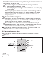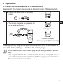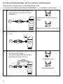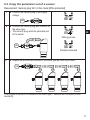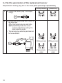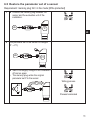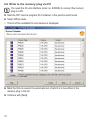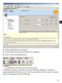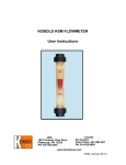
1
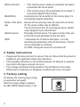
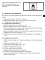
Operating instructions
Memory plug
UK
704930/02 11/2011
E30398
Contents
1 Preliminary note���������������������������������������������������������������������������������������������������3
1.1 Symbols used������������������������������������������������������������������������������������������������3
1.2 Terms used����������������������������������������������������������������������������������������������������3
2 Safety instructions�����������������������������������������������������������������������������������������������4
3 Factory setting�����������������������������������������������������������������������������������������������������4
4 Functions and features����������������������������������������������������������������������������������������5
4.1 Applications without PC���������������������������������������������������������������������������������5
4.2 Applications with PC��������������������������������������������������������������������������������������5
4.3 Basic operating conditions�����������������������������������������������������������������������������5
5 Electrical connection��������������������������������������������������������������������������������������������6
6 Operation�������������������������������������������������������������������������������������������������������������7
6.1 Save the parameter set of a sensor once �����������������������������������������������������7
6.2 Save the parameter set of a sensor continuously ����������������������������������������8
6.3 Copy the parameter set of a sensor �������������������������������������������������������������9
6.4 Set the parameters of the replacement sensor�������������������������������������������10
6.5 Restore the parameter set of a sensor�������������������������������������������������������� 11
6.6 Write to the memory plug via PC�����������������������������������������������������������������12
6.7 Read from the memory plug via PC������������������������������������������������������������14
6.8 Use the memory plug as data carrier����������������������������������������������������������16
6.9 Operating indicators������������������������������������������������������������������������������������17
7 Configure the memory plug�������������������������������������������������������������������������������18
7.1 Configuration via PC������������������������������������������������������������������������������������18
7.2 Configuration via teach button���������������������������������������������������������������������20
8 Scale drawing����������������������������������������������������������������������������������������������������22
9 Technical data����������������������������������������������������������������������������������������������������23
10 Troubleshooting�����������������������������������������������������������������������������������������������25
2
1 Preliminary note
1.1 Symbols used
►
>
→
Instructions
Reaction, result
Cross-reference
Important note
Non-compliance can result in malfunction or interference.
Information
Supplementary note.
UK
LED on
LED off
LED flashes slowly (1 Hz)
LED flashes quickly (4 Hz)
LED flickers
1.2 Terms used
Memory plug
Plug with storage medium
Memory plug empty Setting at the factory.
No parameter set is saved in the memory plug.
The memory plug has to be connected to a sensor or a
PC system in order to save a valid parameter set.
Memory plug full
A valid parameter set is available in the memory of the
memory plug.
Memory plug trans- The memory plug is transparent if after successful saving
parent
of the parameters all unfiltered sensor signals are transmitted to the higher-level system.
For further data operation the operating voltage or the
connection sensor - memory plug must be interrupted
once.
3
[Write protected]
[Read/Write]
Sensor of the same
type
Identical sensor
IODD
• If the memory plug is empty (no parameter set saved),
a parameter set can be saved.
• If the memory plug is full (a parameter set is saved), it
is protected against further writing.
A parameter set can be written to the memory plug. It is
not protected against overwriting.
Sensors of the same type have the same IO-Link device
ID. The series number may be different.
The IO-Link device ID is an unambiguous device identification assigned by the manufacturer.
Physically identical device: The series number of the sensor and the saved parameter set are the same.
= abbreviation for IO Device Description. It is a file
describing the parameters of the IO-link devices. This file
can be interpreted by machines.
An IODD is assigned to each IO-Link device ID.
2 Safety instructions
• Please read this document prior to set-up of the unit. Ensure that the product is
suitable for your application without any restrictions.
• If the operating instructions or the technical data are not adhered to, personal
injury and/or damage to property can occur.
• If you change parameters during operation, this will influence the function.
Ensure that no malfunction or dangerous conditions will occur in the plant.
3 Factory setting
On delivery the memory plug is empty
(no parameter set saved).
When the supply voltage is applied,
the LED WRITE flashes slowly (1 Hz).
4
In this state one parameter set can be
written to the memory plug once.
Then it changes to the mode [Write
protected].
4 Functions and features
The memory plug saves parameter sets of IO-Link devices. It offers the following UK
options:
• Bi-directional backup for IO-Link V1.1 sensors.
• Bi-directional backup for IO-Link V1.0 sensors from ifm electronic.
• Preconfiguration as data carrier via PC.
4.1 Applications without PC
• Save the parameter set of a sensor once → 6.1.
• Save the parameter set of a sensor continuously → 6.2.
• Copy the parameter set of a sensor (copy to several sensors of the same type;
e.g. in series production or for fast set-up) → 6.3.
• Set the parameters of replacement sensors (without using further tools, without
configuration tools or menu handling) → 6.4.
• Restore the parameter set of a sensor (e.g. during start-up of an installation)
→ 5.5.
4.2 Applications with PC
• Write to the memory plug via PC (save the parameter set in the memory plug)
→ 6.6.
• Read the memory plug via PC → 6.7.
• Use the memory plug as data carrier → 6.8.
• Configure the memory plug via PC → 7.1.
4.3 Basic operating conditions
• Negative switching sensors are not supported.
• The memory plug cannot be used with IO-Link actuators.
• The memory plug is intended for saving the data of IO-Link sensors used
without IO-Link master.
5
• Data in the parameter set of the sensor protected by an access code cannot be
overwritten by the memory plug.
The memory plug saves / writes data after the following operations:
• After application of the supply voltage.
• After interrupting and restoring the connection between the memory plug
and the sensor.
After saving the parameters all sensor signals are linked through without
being changed. The output function of the sensor, its quality and speed
remain unchanged. An integrated memory plug does not influence the
complete system.
Recommended operating mode:
Operation in the [Write protected] mode is recommended. This mode ensures that a parameter set is not unintentionally overwritten. In the [Read/
Write] mode the memory plug is not write-protected!
The manufacturer of an IO-Link sensor is responsible for providing all
parameters necessary for an exchange. The memory plug reads this information from the sensor and saves exactly these parameters.
The memory plug cannot be used in a system with IO-Link master. The
functionality of the system cannot be guaranteed.
5 Electrical connection
The memory plug is an accessory intended for connection to IO-Link
devices.
1
1
1: Sensor
2: Memory plug
6
2
1
BN
2
2
WH
4
4
BK
3
3
BU
L+
Out 2
Out 1
L
6 Operation
6.1 Save the parameter set of a sensor once
Requirement: The memory plug is used as delivered (empty / [Write protected]).
1 ►► Connect the memory plug to the supply
voltage.
Ub
2
►► Connect memory plug and sensor.
>> The memory plug reads the parameter set
of the sensor and saves it.
P
Ub
UK
Reading process
P
Process terminated.
Memory plug full / [Write protected].
The empty memory plug can carry out this process only once. It can however be
reset to the factory setting (→ 7 Configure the memory plug).
Do not install a brand new memory plug before setting the sensor parameters.
If it is integrated before the parameter setting has been completed, it saves
a non-optimised parameter set and any further change in the parameter set
of the connected sensor is undone.
7
6.2 Save the parameter set of a sensor continuously
Requirement: memory plug in the [Read/Write] mode
To change from [Write protected] to [Read/Write] → 7 Configure memory plug.
1 ►► Connect the memory plug between the
sensor and the evaluation unit of the
installation.
Display when the memory plug is
empty
Ub
P
Display when the memory plug is full
2
The parameter set of the sensor is changed
(P → P1).
Ub
3
P1
►► Disconnect the memory plug from the sensor and connect it again.
>> The memory plug reads the changed
parameter set P1 and saves it.
P1
Ub
8
P1
Reading process
Process terminated
6.3 Copy the parameter set of a sensor
Requirement: memory plug full / in the mode [Write protected]
1 ►► Connect the memory plug to the supply
voltage.
Ub
2 ►► Connect the memory plug with a sensor of
the same type.
>> The memory plug writes its parameter set
to the sensor.
P
UK
Writing process
Ub
Process terminated
3
►► Repeat the process with sensors of the same type as often as you wish.
Ub
P
This process only works for sensors of the same type (= sensors with the same IO-Link
device ID).
9
6.4 Set the parameters of the replacement sensor
Requirement: memory plug full / in the mode [Write protected] or [Read/Write]
[Write protected]
[Read/Write]
Writing process
Writing process
Process terminated
Process terminated
1 ►► Connect the memory plug to the supply
voltage.
Ub
2 ►► Connect the memory plug with a sensor of
the same type.
If the memory plug is used in the
[Read/Write] mode, the sensor
must have the factory setting. If in
doubt reset the sensor.
>> The memory plug writes its parameter set
to the new sensor.
P
Ub
10
6.5 Restore the parameter set of a sensor
Requirement: memory plug full / in the mode [Write protected]
1 ►► Connect the memory plug between the
sensor and the evaluation unit of the
installation.
Ub
P
UK
2 The parameter set of the sensor is changed
(P → P1).
Ub
P1
►► Switch the supply voltage of the installation
off and on again.
>> The memory plug writes the original
parameter set P to the sensor.
I
0
P
Writing process
Process terminated
11
6.6 Write to the memory plug via PC
You need the IO-Link interface (order no. E30396) to connect the memory
plug to a PC.
►► Start the FDT service program ifm Container in the point-to-point mode.
►► Select offline mode.
>> The list of the available IO-Link devices is displayed.
►► Mark the IO-Link sensor the parameter set of which is to be written in the
memory plug in the list.
►► Continue with [Next].
12
UK
►► Set the parameters as requested.
►► Connect the memory plug via the IO-Link interface.
►► Click on the symbol [Download].
>> The parameter set is saved in the memory plug.
If the Memory Plug is connected to a sensor after this operation, it writes the
saved parameter set in the sensor. Then the parameter set of the sensor is saved
again in the Memory Plug for verification.
13
6.7 Read from the memory plug via PC
►► Connect the memory plug via the IO-Link interface.
►► Start the FDT service program ifm Container in the point-to-point mode.
►► Activate the option field [Automatic device selection (online)] and continue with
[Next].
14
>> The memory plug transmits its saved parameter set.
UK
>> The parameter set in the memory plug is displayed together with the photo of
the sensor concerned (here TR2432).
•
15
This allows the following possibilities:
• Check the current parameter setting.
• Change the current parameter setting.
• Save the changed parameter set in the Memory Plug.
►► Click on the symbol [Download].
If the Memory Plug is connected to a sensor after this operation, it writes the
saved parameter set in the sensor. Then the parameter set of the sensor is
saved again in the Memory Plug for verification.
• Save the changed parameter set in the FDT service program ifm Container.
►► Click on the symbol [Save].
6.8 Use the memory plug as data carrier
Memory plugs can be used as external storage medium:
►► When the installation has been set up, keep units with saved parameter sets in
a safe place.
16
6.9 Operating indicators
No supply voltage.
Memory plug with factory setting (= no parameter set saved)
After one writing process change to the [Write protected] mode.
Memory plug with saved parameter set in the [Write protected] mode.
UK
Memory plug without saved parameter set in the [Read/Write] mode.
Memory plug with saved parameter set in the [Read/Write] mode.
Memory plug reads the parameter set of the sensor.
Memory plug writes the saved parameter set in the sensor.
Memory plug in the [Read/Write] mode;
error in data processing.
Memory plug in the [Write protected] mode;
error in data processing.
The connected sensor is not of the same type.
This state remains until a sensor of the same type is connected or the
voltage supply is interrupted.
17
7 Configure the memory plug
7.1 Configuration via PC
►► Start the FDT service program ifm Container in the point-to-point mode.
►► Select offline mode.
>> The list of the available IO-Link devices is displayed.
►► Mark the memory plug in the list.
►► Continue with [Next].
18
►► Connect the memory plug via the IO-Link interface.
►► Click on the symbol [Connect].
>> The current setting of the memory plug is indicated in the status display (1).
UK
1
2
3
4
1: status display
2: button [Reset]
3: button [Write Protect]
4: button [Read-Write]]
►► Press the requested button to change the setting:
-- Reset] (2) restores the factory setting of the memory plug.
-- The memory plug is set to the mode [Write protected] by [Write Protect] (3).
-- The memory plug is set to the mode [Read/Write] by [Read-Write] (4).
>> The command is immediately sent to the connected memory plug, the status
display (1) is updated.
19
7.2 Configuration via teach button
3
1
1
1
1
1
BN
2
2
2
2
WH
4
4
4
BK
3
3
3
BU
2
4
3
L+
L
T
1: sensor
2: memory plug
3: teach button (available as accessories; order no. E30405)
T = button
No sensor may be connected.
►► Press the teach button for the indicated time (the end of the time span is signalled by a change of the LED display; → following figures).
Change from [Write protected] to [Read/Write]
+Ub
t [s]
0
A
B
A: LED display memory plug empty
B: LED display memory plug full
20
10
<13
Change from [Read/Write] to [Write protected]
+Ub
t [s]
0
10
<13
A
B
UK
A: LED display memory plug empty
B: LED display memory plug full
Restore the factory setting of the memory plug
+Ub
t [s]
0
10
15
<18
A
A: LED display memory plug
21
8 Scale drawing
25
M12x1
18
22
52
LED
M12x1
2
Dimensions in mm
1: connection for voltage supply and output signals
2: connection for sensor
22
9 Technical data
IO-Link master
The memory plug acts as master if it is connected with a sensor.
Type of transmission
COM1 (4.8 kBaud), COM2 (38.4 kBaud),
(COM3 [230 kBaud] is not supported)
IO-Link revision
1.1
SDCI standard
IEC 61131-9 (Draft)
Number of ports
1
Port class
A
Pin 2
electrically connected
Smallest detectable current
3
for sensor detection [mA]
UK
IO-Link device
The memory plug acts as device if it is used with the ifm Container FDT service program.
Type of transmission
COM2 (38.4 kbaud)
IO-Link revision
1.1
Profile
no profile
SIO mode
no
Required master port class
A (for parameter setting)
Analogue process data
none
Binary process data
none
Min. process cycle time [ms]
2.5
Operating voltage [V]
Current consumption [mA]
Load current [A]
Voltage drop [V]
Short-circuit protection
Reverse polarity protection
Overload protection
Storage capacity
18 … 32 DC
< 35
0.5 / 2 (50 ms)
0.5
according to the connected sensor
yes
according to the connected sensor
max. 2 Kbytes
23
Power-on delay time
Ambient temperature [°C]
Storage temperature [°C]
Protection rating
Protection class
Insulation resistance [MΩ ]
Shock resistance
Vibration resistance
EMC
Housing materials
Connection
24
according to the baud rate, data organisation, storage
volume and communication behaviour of the connected
sensor; typical values [s]:
Storage volume
Baud rate
0.1 K
0.5 K
1K
2K
4.8 kbaud
4.5 s
10 s
20 s
40 s
38.4 kbaud
0.5 s
1.3 s
2.5 s
5s
Example: For a sensor with approx. 20 parameters, a
storage volume of 0.1 K and a baud rate of 38.4 kBaud
the memory plug needs a power-on delay time of max.
0.5 s + delay time of the connected sensor.
If the parameters of sensor and memory plug are identical, this time is reduced considerably.
-25...70
-40…85
IP 65, IP 67
III
> 100 (500 V DC)
DIN IEC 68-2-27 50 g (11 ms)
DIN IEC 68-2-6 20 g (10...2000 Hz)
EN 61000-6-2
PA PACM 12 (TROGAMID); PET; sealing: FPM (Viton);
coupling nut: high-grade stainless steel (316L/1.4404);
connector: TPU
M12 connector
10 Troubleshooting
For all errors the following applies:
• The parameter set in the memory plug remains. It is not damaged by faulty
reading or writing.
• The error remains until it has been removed.
• If the memory plug detects an error, the transmission of the sensor output
(OUT1, pin 4) to the higher-level system is stopped.
Error in data processing
Cause of the fault
Sensor cable removed during transmission.
Unknown sensor connected, e.g.
•IO-Link 1.0 sensor of another manufacturer.
•Sensor not equipped with IO-Link .
Parameter set of the connected sensor >
2048 bytes.
The sensor does not support any saving
of data.
Sensor locked, writing impossible.
Solution
►► Connect the sensor cable to the memory
plug again.
►► Connect an IO-Link 1.0 sensor from ifm
electronic.
►► Connect an IO-Link 1.1 sensor.
►► Connect sensors requiring a storage
capacity of less than 2048 bytes (→ data
sheet of the sensor).
►► Connect sensors supporting IO-Link
and saving of data (→ data sheet of the
sensor).
►► Connect an unlocked sensor or unlock
sensor.
The parameter set of the connected sensor does not correspond to the parameter set in
the memory plug.
Cause of the fault
Solution
The connected sensor is not of the same
►► Connect a sensor of the same type ( =
type.
sensor with the same IO-Link device ID).
More information at www.ifm.com
25
UK