1
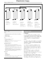
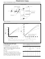
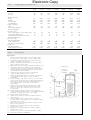
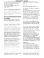
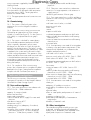
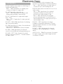
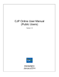
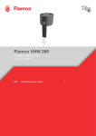
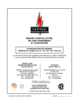
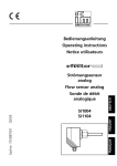
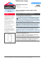
Electronic Copy
CI/SfB
(53.3)
Heatrae Sadia Heating Limited
Hurricane Way
Norwich
Norfolk NR6 6EA
Tel: 01603 424144 Fax: 01603 409409
Designated by Government
to issue
European Technical
Approvals
Product
• THIS CERTIFICATE REPLACES
CERTIFICATE NO 92/2743
AND RELATES TO MEGAFLO
UNVENTED HOT WATER
STORAGE SYSTEMS.
• The systems are for use in
domestic, commercial and
public buildings with domestic
hot and cold water services to
BS 6700 : 1987.
• The systems are for connection
to mains water supply at
pressures up to 12 bar.
• It is essential, for reasons of
safety and performance, that
the systems are installed and
maintained in accordance with
this Certificate.
X
Agrément
Certificate
No 95/3094
MEGAFLO UNVENTED HOT WATER STORAGE SYSTEMS
Système d’eau chaude sanitaire
Heißwasserbereiter
Regulations, Legislation and Byelaws
1 The Building Regulations (England and Wales)
The Secretary of State has agreed with the British Board of Agrément
the aspects of performance to be used by the BBA in assessing the
compliance of unvented hot water storage systems with the Building
Regulations. In the opinion of the BBA, the position of Megaflo Unvented Hot
Water Storage Systems under the Regulations, if used in accordance with the
provisions of this Certificate, is as stated in Detail Sheet 1.
2 The Building Standards (Scotland) Regulations
In the opinion of the BBA, the position of Megaflo Unvented Hot
Water Storage Systems under the Regulations, if used in accordance
with the provisions of this Certificate, is as stated in Detail Sheet 1.
3 The Building Regulations (Northern Ireland)
In the opinion of the BBA, the position of Megaflo Unvented Hot
Water Storage Systems under the Building Regulations, if used in
accordance with the provisions of this Certificate, is as stated in Detail
Sheet 1.
4 The Health and Safety at Work etc Act 1974 and the Health and Safety
at Work (Northern Ireland) Order 1978
In the opinion of the BBA, the position of Megaflo Unvented Hot Water
Storage Systems under the Act and Order, if used in accordance with the
provisions of this Certificate, is as stated in Detail Sheet 1.
5 Water Byelaws and Regulations
In the opinion of the BBA, the position of Megaflo Unvented Hot Water
Storage Systems under the Byelaws and Regulations, if used in accordance
with the provisions of this Certificate, is as stated in Detail Sheet 1.
Readers are advised to check that this Certificate has not been withdrawn or superseded by a later issue, by either referring to the
Index of Current BBA Publications or contacting the BBA direct (Telephone Hotline 01923 662900).
Electronic
Copy
6.3 In granting this Certificate, the BBA makes no
Conditions of Certification
representation as to the presence or absence of
patent rights subsisting in these products and/or as
to the legal right of Heatrae Sadia Heating Limited
to market, install or maintain these products.
6 Conditions
6.1 The quality of materials and the method of
manufacture have been examined and found
satisfactory by the BBA and must be maintained to
this standard during the period of validity of this
Certificate. This Certificate will remain valid for an
unlimited period provided that:
(a) the specification of the products is unchanged,
and
(b) the manufacturer continues to have the
products checked by the BBA.
6.2 Where reference is made in this Certificate to
any Act of Parliament, Regulation made thereunder,
Statutory Instrument, Code of Practice, British
Standard, manufacturer’s instruction or similar
publication, it shall be construed as reference to
such publication in the form in which it is in force at
the date of this Certificate.
6.4 It should be noted that any recommendations
relating to the safe use of these products which are
contained or referred to in this Certificate are the
minimum standards required to be met when the
products are used. They do not purport in any way
to re-state the requirements of the Health and Safety
at Work etc Act 1974, or of any other statutory or
Common Law duties of care, or of any duty of care
which may in the future exist; nor is conformity with
such recommendations to be taken as satisfying the
requirements of the 1974 Act or of any other
present or future statutory or Common Law duties of
care. In granting this Certificate, the BBA does not
accept responsibility to any person or body for any
loss or damage incurred in respect of personal
injury arising as a direct or indirect result of the use
of these products.
In the opinion of the British Board of Agrément, Megaflo Unvented Hot Water Storage Systems
are fit for their intended use if used as set out in this Certificate. Certificate No 95/3094 is
accordingly awarded to Heatrae Sadia Heating Limited.
On behalf of the British Board of Agrément
Date of issue: 22nd February 1995
British Board of Agrément
P O Box No 195, Bucknalls Lane
Garston, Watford, Herts WD2 7NG
Fax: 01923 662133
Director
For technical or additional
information, tel: 01923 670844.
For information about Agrément
Certificate validity and scope, tel:
©1995
Hotline: 01923 662900
Electronic Copy
CI/SfB
(53.9)
Heatrae Sadia Heating Limited
X
Certificate No 95/3094
MEGAFLO UNVENTED HOT WATER
STORAGE SYSTEMS
DETAIL SHEET 2
Second issue*
Components
• THIS DETAIL SHEET LISTS THE COMPONENTS APPROVED FOR USE ON MEGAFLO UNVENTED HOT
WATER STORAGE SYSTEMS.
• Each product Detail Sheet lists the components that are required to be factory fitted and others which are
supplied separately for fitting by the installer.• The BBA has assessed each of the components as suitable
for purpose.
This Detail Sheet must be read in conjunction with the Front Sheet and the relevant Detail Sheets.
Component
Manufacturer/supplier
and component number
Setting
Size
Line strainer
Reliance Water Controls LS75
—
¾”
Pressure control valve
Honeywell D07
Desbordes 9BisFX
Reliance Water Controls 312
3 bar
3 bar
3 bar
¾”
¾”
¾”
Check valve
Reliance Water Controls SC75
—
22 mm
Combined control valve set
Reliance Water Valves 2014
expansion valve set at
8 bar
Combined temperature and
pressure relief valve
Flamco
Reliance
90°C/10 bar
90°C/10 bar
¾”
¾”
Tundish
Reliance Water Controls
—
22 mm to 1”
Immersion heater
Megaflo 90105151
Direct non-self-resetting
thermal cut-out
Cotherm Type TUS 0228
77° to 83°C
Direct thermostat
Cotherm Type TUS 0228
10° to 70°C
Indirect non-self-resetting
thermal cut-out
Cotherm Type GTLHR 038
75° to 85°C
Indirect thermostat
Cotherm Type GTLH 3101
10° to 70°C
Motorized valve*
Honeywell V4043
Danfoss DMV2C
Sunvic SZV 2212 F
1¾” BSP
*It is essential on indirectly heated systems that the motorized valve supplied with the system is installed and is not substituted by
any other motorized valve which may exist and be in service at the site of installation, eg a motorized valve installed in a central
heating circuit.
Note: The replacement or servicing of any components must be carried out, using the Megaflo Installation Manual, by a competent
person (see section 15 of each system Detail Sheet), or by Heatrae Sadia Heating Limited under their responsibility as the
product manufacturer, including that required by their warranty, using components supplied by Heatrae Sadia Heating Limited.
Readers are advised to check the validity of this Detail Sheet by either referring to the Index of Current BBA Publications or contacting
the BBA direct (Telephone Hotline 01923 662900).
Electronic Copy
On behalf of the British Board of Agrément
Date of Second issue: 4th February 1997
Director
*Original Detail Sheet issued 22nd February 1995. This amended version includes changes to components list (indirect
thermal cut-out and thermostat).
British Board of Agrément
P O Box No 195, Bucknalls Lane
Garston, Watford, Herts WD2 7NG
Fax: 01923 662133
For technical or additional
information, tel: 01923 670844.
For information about Agrément
Certificate validity and scope, tel:
©1997
Hotline: 01923 662900
Electronic Copy
CI/SfB
(53.3)
Heatrae Sadia Heating Limited
MEGAFLO DIRECT UNVENTED HOT WATER
STORAGE SYSTEM
X
Certificate No 95/3094
DETAIL SHEET 3
Product
• THIS DETAIL SHEET RELATES TO THE MEGAFLO DIRECT UNVENTED
HOT WATER STORAGE SYSTEM WITH A RANGE OF CAPACITIES
FROM 70 TO 300 LITRES, A NOMINAL OPERATING PRESSURE OF 3
BAR AND SUPPLIED WITH ONE, TWO OR THREE 3 kW IMMERSION
HEATERS.
• The system is for use with mains or other suitable potable water supply
pressures up to and including 12 bar.
• Satisfactory outlet flow rates can only be achieved where the flow rate
available at the entry to the system is adequate (see section 5).
• It is essential, for reasons of safety and performance, that the product is
installed and maintained in accordance with the requirements of this
Detail Sheet by a competent person (see section 12, regarding
Maintenance and section 15 for the definition of a competent person).
This Detail Sheet must be read in conjunction with the Front Sheet and Detail
Sheet 1, which give Conditions of Certification and the product’s position
regarding the Building Regulations, respectively.
Technical Specification
1 Description
1.1 The Megaflo Direct Unvented Hot Water
Storage System is for use in domestic, commercial
and public buildings for connection to domestic hot
and cold water services to BS 6700 : 1987, and
comprises the components shown in Figure 1. The
storage capacities and main dimensions are listed
in Table 1.
1.2 The system generally comprises a stainless
steel storage cylinder supplied with one, two or
three immersion heaters. The system is for free
standing installation and connects to a cold feed
supply as indicated in Table 1.
1.3 The cylinder is insulated with polyurethane
(PU) hard foam and covered in a white polyvinyl
chloride (PVC) coated galvanized steel outer casing.
1.4 For safety of the system, electrical control devices
and the combined temperature and pressure relief
valve are factory fitted. Other components
including additional safety devices are supplied
separately for fitting on site (see Figure 1 and
section 2.1) by a competent person (see section 15).
1.5 Factory production control is exercised during
the manufacture and assembly of each of the
components including visual examination,
dimensional checks and performance tests. Each
storage cylinder is pressure tested and examined
for leaks during manufacture and prior to dispatch.
1.6 When the system is commissioned an air gap
is trapped at the top of the storage cylinder to
accommodate expansion of the heated water (see
Figure 2).
2 Delivery and site handling
2.1 The complete system is delivered to site
boxed. The following components (see also Detail
Sheet 2 of this Certificate) are supplied separately
with each storage cylinder for fitting on site by a
competent person, all other components are factory
fitted:
cold water control valves to include:
pressure reducing valve
strainer, check valve and expansion relief valve
tundish
immersion heater(s).
2.2 When the system is required to be stored, it
must be stored in a dry environment and protected
from damage.
2.3 The system must be carefully handled and
kept in the delivery carton until required for siting in
position. The weight of each system empty and full
is stated in Table 1 and on the label attached to
each cylinder.
3 Labelling/marking
The system carries a label (or labels) bearing the
information set out in Table 2 and is supplied with
a comprehensive installation/user manual.
Readers are advised to check that this Detail Sheet has not been withdrawn or superseded by a later issue, by either referring to the
Index of Current BBA Publications or contacting the BBA direct (Telephone Hotline 01923 662900).
Electronic Copy
Table 1
Storage capacities and dimensions
water storage capacity (litres)
at 1 bar
at 3 bar
cylinder size (mm):
height
diameter
overall height
overall diameter
weight of unit (kg):
empty
at 3 bar (full operating
pressure/capacity)
connection sizes:
mains water supply to
control valves (mm)
control vlaves (BSP inches)
temperature and pressure relief valve
discharge (BSP inches female)
immersion heater:
rating at 240 V (kW)
heater length (mm)
clearance for removal (mm)
Manufacturer’s system reference*
DD145
DD170
DD210
D70
D125
DD250
DDD250
DD300
DDD300
84
92
130
140
145
155
170
182
187
199
223
236
267
283
717
450
886
525
1023
450
1192
525
1149
450
1318
525
1306
450
1475
525
1407
450
1576
525
1659
450
1828
525
1973
450
2142
525
25
117
29
169
31
186
36
218
42
241
49
285
58
341
22
22
22
22
22
22
22
¾
¾
¾
¾
¾
¾
¾
¾
¾
¾
¾
¾
¾
¾
3
280
280
3
280
280
3
280
280
3
280
280
3
280
280
3
280
280
3
280
280
*D prefix refers to systems with one immersion heater, DD prefix refers to systems with two immersion heaters and DDD prefix to systems with three
immersion heaters.
Figure 1
General layout
Key to Figure 1
1
Storage cylinder manufactured from 1 mm thick stainless steel to
BS 1449 : Part 2 : 1983, grade 316 S12 or duplex 2304.
2
Heater flange, stainless steel threaded boss(es) welded to the
storage cylinder to accept the immersion heater(s).
3
Insulation, expanded polyurethane foam 35 mm thick injected
between storage cylinder and outer casing.
isolating valve
4
Outer casing, white PVC coating over galvanized mild steel
sheet.
connection
for balanced
cold supply
5
Cold water control valves to include: pressure reducing valve
(set at 3 bar), strainer, check valve and expansion valve (set
at 8 bar). Supplied separately for fitting by a competent person
(see Detail Sheet 2 of this Certificate).
6
Cold water feed, cylinder connection, to suit a 22 mm diameter
compression fitting to BS 864 : Part 2 : 1983.
7
Combined temperature and pressure relief valve. The valve has
a set temperature of 90°C and a set pressure of 10 bar.
Factory fitted.
8
Immersion heater(s), to BS 3456 : Section 2.21 : 1972.
Heater unit incorporates a thermostat and non-self-resetting
thermal cut-out to BS 3955 : 1986. Thermostat set to a
temperature of 65°C and cut-out designed to operate when
the stored water reaches 80°C.
9
Hot water draw-off, 22 mm diameter stainless steel tube to
BS 1449 : Part 2 : 1983, grade 316, to suit compression
fitting to BS 864 : Part 2 : 1983.
11
Drain valve to BS 2879 : 1980(1988).
10
cold
feed
7
3
1
5
9
to discharge
2
8
Tundish 22 mm compression inlet and 1” BSP female thread
outlet connection.
10
hot
supply
4
6
11
2
Electronic Copy
Figure 2
Expansion system
operating cycle
system commissioning
air gap
cold filling
cylinder at 1 bar
— cold feed open
— hot tap open
— as system fills water
flows out of hot tap
— water cold
— pressure = 0 bar
—
—
—
—
—
—
Table 2
cold feed open
hot tap closed
water cold
pressure = 1 bar
volume of air gap = 10%
volume of water = 90%
stage 1
stage 2
water heated
cylinder at cold
supply pressure
—
—
—
—
cold feed open
hot tap closed
water cold
pressure ⭐ 3 bar max
controlled by pressure
control valve
— volume of air gap = 5%
— volume of water = 95%
— cold feed open
— hot tap closed
— water heated to 60°C
and expands in cylinder
— cylinder air bubble
compresses
— pressure ⭐ 7 bar
— volume of air gap < 5%
— volume of water > 95%
stage 3
hot water drawn off to
stage 1 level
— cold feed open
— hot tap open
— water level drops to
stage 1 level, no cold
water fed into cylinder
— water hot
— pressure = 3 bar
— volume of air gap = 5%
— volume of water = 95%
Design Data
Labels
General
4 General
1 The BBA identification mark incorporating the number of this Certificate.
2 The system uses BEAB (British Electrotechnical Approvals Board) approved
electrical controls.
3 Manufacturer’s name.
4 Product code number.
5 Unique serial number.
6 The system is an unvented system.
4.1 The Megaflo Direct Unvented Hot Water
Storage System (see Figure 3) has been assessed
in accordance with MOAT No 38 : 1986. When
used in accordance with this Detail Sheet the
system will perform in a safe and satisfactory
manner.
Design
1
2
3
4
Maximum water supply pressure (bar).
Operating pressure (bar).
Pressure control valve setting (bar).
Expansion system relief via the combined temperature and pressure relief
valve (bar).
5 Immersion heater — Power/voltage — Type/BS/Length.
6 Storage capacity (litres).
7 Weight of system — full (kg).
4.2 The hot water system capacity, etc should be
selected in accordance with the recommendations
of BS 6700 : 1987 to meet the demands made
upon the installation.
Safety warnings/conditions
1 Installation to be carried out only by a competent person.
2 The removal/replacement of any component must be carried out only by
a competent person using components supplied by Heatrae Sadia Heating
Limited in accordance with their instructions.
3 Any malfunction of the system such as that resulting in discharge of water to
the tundish from the combined temperature and pressure relief valve to be
reported to a competent person after switching off the heat source and prior
to any further use of the system.
4 The installation of the system is subject to approval under the Building
Regulations, Water Byelaws and Regulations, the Health and Safety at Work
etc Act 1974 (where appropriate) and the Health and Safety at Work
(Northern Ireland) Order 1978 (where appropriate).
4.3 The pressure and flow available from the
water mains should be obtained from the local
water undertaker or by testing existing supplies to
establish the likely performance of the system at
peak periods.
4.4 It is essential, for reasons of safety and
performance, that installation of the system is
undertaken only by a competent person working in
accordance with this Detail Sheet.
Installer* details
1 Space for:
(a) Name
(b) Address
(c) Telephone number
(d) Completion date
(e) Registration No .....
2 A declaration that installation has been in accordance with BBA Certificate
No 95/3094 with space for the signature of the installer*.
4.5 The data shown in Tables 3 and 4 of this
Detail Sheet represent the results of tests carried out
by the BBA. Slight variations in the results occur
with changes in the water mains supply pressure.
*The installer must meet the definition of a competent person as defined in section 15.2.
3
Electronic Copy
Figure 3
Schematic layout — direct
combined temperature
and pressure relief valve
cold water control valves
hot draw-off
expansion
valve
pressure
control
valve
isolating
valve
tundish
cold feed
immersion heater,
non-self-resetting
thermal cut-out
and thermostat
check
valve
strainer
balanced pressure
cold draw-off
discharge pipe
to safe position
[see section 16(2)]
drain valve
Figure 4
Flow rates
70
*static supply pressures of incoming water supply
hot/cold mixed
8 bar*
4 bar*
3 bar*
flow out ( min–1) of the system
50
hot
8
4
3
2
40
bar*
bar*
bar*
bar*
30
1 bar*
20
flow out ( min–1) of the system
60
1 bar*
40
30
20
10
0
2 bar*
50
mixed water at 40º C, mixed from:
60% hot water at 60ºC and
40% cold water at 10ºC
10
10
20
30
40
50
0
10
flow available ( min–1) at entry to system
20
30
40
50
60
70
flow available ( min–1) at entry to system
Notes:
(1) flow rates shown apply to situations where the supply is capable of supplying an adequate dynamic pressure
(2) the graph represents the results of tests carried out by the BBA
(3) where static water supplies are less than 1 bar, consult Heatrae Sadia Heating Limited or the BBA
5 Hot water storage and supply
Table 3
Hot water storage
5.1 The capacities of the system range are
comparable with conventional systems (see
Table 1). When heated to 60°C the system can
supply 70% of the storage capacity at the mean
temperature given in Table 3.
Heating, re-heating and water draw-off
temperature
A
System Immersion Heat-up
ref
heater
time
(kW)
Flow rates
5.2 The flow rates achieved at the hot water
draw-off point will depend on all the normal factors
including the layout of the pipework from the tap to
the cylinder, the cold water supply pressure and
the flow rate available at the supply to the system.
4
B
C
D
E
F
Percentage
Mean
Re-heating
Top
Volume
and quantity
draw-off
time
immersion available
heated to within temperature
heat up
above
10°C of set
time
40°C
temperature
(minutes) (%)
(litres)
(°C)
(minutes) (minutes)
(litres)
D70
3
86
72
50
59
65
n/a
n/a
D125
3
144
75
94
60
108
n/a
n/a
D145
3
160
74
107
60
131
110
60
DD170
3
191
75
127
60
149
108
59
DD210
3
209
73
153
60
174
85
42
DD250
3
263
73
182
60
207
92
44
DD300
3
292
72
210
59
270
97
45
Electronic Copy
5.3 For design purposes the graphs in Figure 4
show the relationship between:
Table 4
flow available,
mains supply pressure, and
the maximum hot water flow rate out of the
system*.
Standing energy losses(1)
System ref
D70
D125
DD145
DD170
DD210
DD250
DD300
*Flow characteristics shown in the graphs reflect the worst
combination of cold water control components that may be
installed (see Detail Sheet 2 of this Certificate).
5.4 The hot/cold mixed flows are for draw-off
temperatures of 40°C (assume 60% at 60°C and
40% at 10°C).
(W)
Energy loss(2)
maximum daily
(kWh)
76
85
90
95
98
107
118
1.82
2.04
2.16
2.28
2.35
2.57
2.83
Heat loss
(1) See section 4.5.
(2) These figures relate to a 45°C differential between the stored water and
ambient temperature.
Heating, re-heating and hot water draw-off
temperature
5.5 The heat-up and re-heat times are comparable
with conventional systems supplying hot water.
Connections
5.12 The system is designed to be connected to
copper tube conforming to BS 2871 : Part 1 :
1971, Tables X, Y and Z, using conventional
plumbing fittings (see Table 1 for details of
connection sizes and threads). The connections are
of adequate size.
5.6 The immersion heater will heat the stored
water from 15°C to 60°C in the time listed in
column A of Table 3.
5.7 The amount of water that can be drawn off
within 10°C of the set temperature is listed in
column B of Table 3, the mean temperature of 70%
of the water drawn off immediately after reaching
60°C in column C and the time taken to re-heat the
stored water to 60°C in column D.
6 Safety
Excessive temperature — Prevention of
explosion — Safe discharge of hot water
6.1 The safety devices provided to ensure that the
temperature of the stored water will not exceed
100°C and safeguard the operation of the system,
are:
Temperature control
5.8 The direct thermostat wired to the
immersion heater is satisfactory for controlling
the temperature of the stored water.
(a) the combined temperature and pressure relief
valve, and
Pressure control
5.9 The pressure control valve is satisfactory for
controlling the pressure of the water supplied from
the water mains or other suitable potable supply.
However, during the heat-up period from cold to
60°C, the water expands and compresses the air
gap at the top of the storage cylinder causing an
increase in pressure to a maximum of 7 bar (see
Figure 2). Under failure conditions the combined
temperature and pressure relief valve ensures the
pressure will not exceed 10 bar. Each storage
cylinder is factory tested to 15 bar.
(b) the non-self-resetting thermal cut-out fitted to the
immersion heater.
Insulation
5.10 The system is provided with adequate
insulation to satisfactorily limit the energy loss
from the stored water and meets the
requirements described in the Building Regulations
1991 (as amended 1994) (England and Wales),
Section 3.2 of Approved Document L1; the
Building Standards (Scotland) Regulations 1990
(as amended), Regulation 22, Standard J3.4; and
Technical Booklet F, Paragraph 3.3 of the Building
Regulations (Northern Ireland) 1994.
Physical contact
6.4 The surfaces of the storage cylinder are
protected by the insulation. In normal use the
temperatures of the surfaces of the various parts of
the system are comparable with those in a
conventional vented hot water storage system.
6.2 The system has a safety warning label
attached to the storage cylinder, bearing an
explanation of the action to be taken in the case of
any malfunction of the system. It is essential that
these instructions are followed.
6.3 The system has adequate provision for safe
disposal of discharges to a tundish from the
combined temperature and pressure relief valve
[see also section 16(2)].
Strength and stability
6.5 The system has adequate resistance to internal
pressures and does not visibly deform when
subjected to a vacuum of 0.1 bar absolute.
6.6 The system’s pressure control devices will
ensure that the operating pressure will be controlled
to a nominal 3 bar and that the design pressure of
10 bar is not exceeded. Each storage cylinder has
5.11 The heat loss of each system while
maintaining the temperature of the stored water at
65°C is shown in Table 4.
5
Electronic
Copy
Sadia Heating Limited under their responsibility as
been satisfactorily pressure tested to 15 bar at the
factory and no permanent deformation or leakage
occurred.
the product manufacturer, including that required
by their warranty, using components supplied by
Heatrae Sadia Heating Limited.
6.7 The weight of the system is stated on the label
attached (see also Table 1); the support arrangements
appropriate to a conventional system apply.
12.3 The system may be drained through the
drain valve.
6.8 Care must be taken to avoid damage to the
system during handling and installation.
12.4 When the system is used in buildings subject
to the Health and Safety at Work etc Act 1974,
an inspection of the system must be carried out
every six months.
Electrical safety
6.9 The thermostat and non-self-resetting thermal
cut-out are approved by BEAB to BS 3955 :
1986. The immersion heater is approved by the
BEAB to BS 3456 : Section 2.21 : 1972. To
ensure safety it is essential that the electrical wiring is
carried out in accordance with BS 7671 : 1992.
13 Site checks
On site the following should be checked:
By the Client
(1) The installer is a competent person — by
reference to his/her identity card.
7 Properties in relation to fire
(2) The system being installed is BBA
Certificated — by reference to the label.
7.1 The expanded polyurethane foam insulant is
covered with a steel outer casing and only a small
area of the insulant will be exposed at connection
boxes. In the presence of a source of ignition, such
as a plumber’s blowlamp, the foam will flame
locally and emit toxic fumes. Flaming and fume
emission will stop when the source of ignition is
removed.
(3) That the installation complies with the BBA
Certificate — by reference to the installer’s
signature on the label attached to the cylinder.
By the Building Control Officer or Approved
Inspector
(1) 1, 2 and 3 as above.
7.2 In service, the steel outer casing encloses the
foam and risk of ignition will be minimal. During
installation care should be exercised when using a
blowlamp to make soldered joints on pipework
adjacent to the cylinder. Installation does not
require soldered joints to be made direct to the
system.
(2) The combined temperature and pressure relief
valve, thermostat(s), non-self-resetting thermal cutout(s) and the immersion heater(s) are as described
in the Certificate.
(3) The tundish and discharge pipework are
correctly located and fitted.
8 Effect on water quality and prevention of
waste of water
14 Durability
The system is manufactured from durable materials
and conventional plumbing components and will
have a life equal to that expected of a vented
system. It may be necessary to replace some of the
system components, for example, the immersion
heater(s), thermostat(s), etc (see section 12.2 and
Detail Sheet 2 of this Certificate).
The system is listed by the Water Byelaws Scheme.
9 Watertightness
The storage cylinder remains watertight at 1.5 times
the design pressure, ie factory tested to 15 bar.
10 Noise
The system is quiet in normal operation, the flow of
water being via conventional water pipe fittings,
and compares favourably with a vented hot water
storage system.
Installation
15 The installer
15.1 It is essential, for reasons of safety and
performance, that the installation, commissioning
and maintenance of the system is carried out by a
person with suitable training and practical
experience. However, the assessment of training
arrangements and continuing competence of
installers falls outside the scope of this Certificate.
11 Physiological effects
The insulation used is a conventional material. It
will not encourage vermin or bacteria and is not
susceptible to damage from moisture.
12 Maintenance
12.1 It is recommended that annually a competent
person inspects and cleans the line strainer.
15.2 It is the view of the Department of the
Environment, and stated in its Approved
Document G3, that, to meet the requirements of the
Building Regulations 1991 (as amended 1994)
(England and Wales), concerned with unvented
12.2 The replacement or servicing of components
must be carried out by a competent person, using
the Megaflo Installation Manual, or by Heatrae
6
Electronic(4) Copy
Electrical wiring must be carried out in
hot water storage systems, installations should be
undertaken by a competent person, defined as
‘one holding a current Registered Operative Identity
Card for the installation of unvented domestic hot
water storage systems, issued by the Construction
Industry Training Board (CITB), the Institute of
Plumbing, the Association of Installers of Unvented
Hot Water Systems (Scotland and Northern
Ireland), or an equivalent body’.
accordance with the IEE Wiring Regulations. The
immersion heater circuit must be protected by a
suitably rated fuse, eg 13 A, and an isolating
switch with double pole disconnection.
17 Procedure
Summary of installation procedure
17.1 The storage cylinder is located in position
(see the Megaflo Installation Manual) and the
plumbing connections made to the inlet and outlet
pipes in the same manner as for a conventional
storage cylinder except that the water supply pipe
is taken directly from the mains or other suitable
potable supply, via the line strainer and cold water
control valves (ensuring the arrow markings on the
components are pointing downstream) to the cold
water inlet of the storage cylinder (see Figure 3).
Where balanced pressures are required, the cold
water draw-off is connected as shown in Figure 3,
using components supplied by Heatrae Sadia
Heating Limited.
15.3 In Scotland, it is the requirement of the
deemed-to-satisfy provision to Technical
Standard P3.1 Unvented Hot Water Storage
System for compliance with Regulation 28 of the
Building Standards (Scotland) Regulations 1990
(as amended) that such systems be ‘in the form of a
proprietary unit or package which is the subject of
a BBA Certificate’. The Standard contains no
specific requirements for installers but the
Certificates referred to state that installation must be
undertaken by a competent person, as defined in
section 15.2.
15.4 In Northern Ireland, it is the requirement of
Regulation P6 Deemed-to-satisfy provision for an
unvented hot water storage system that systems with
a capacity not greater than 500 litres, and a heat
input not greater than 45 kW, be manufactured
and installed in compliance with Certificates issued
by the BBA under MOAT No 38 : 1986.
Agrément Certificates will refer to a need for
installation by a competent person, as defined in
section 15.2.
17.2 The discharge pipe is connected to and
from the tundish to a safe and visible termination
point [see section 16(2)]. The air gap at the tundish
must remain clear.
17.3 The appropriate electrical connections are
made.
16 Conditions
18 Commissioning
The following conditions abstracted from the
manufacturer’s instructions must be observed:
18.1 The system is filled with water in the
sequences set out in the Megaflo Installation
Manual.
(1) The system must be connected to a water
supply with a pressure not exceeding 12 bar and
of a quality supplied by a water undertaker under
the Water Byelaws and Water Regulations, as
appropriate.
18.2 When the commissioning instructions are
followed an air gap at the top of the storage
cylinder is formed (see Figure 2). For the system to
work safely it is important that this air gap is
formed.
(2) The combined temperature and pressure relief
valve tundish must be in a clearly visible position
within 500 mm of the cylinder and in the same
compartment as the cylinder. The discharge pipe to
and from the tundish must be of metal and laid to
fall. It must terminate at a visible safe place, such
as a gully, where there is no risk of contact with the
hot water by persons in or about the building.
Further details are given in the BBA Information
No 33 : 1989 Unvented Hot Water Storage
Systems — Hot Water Discharges from Safety
Devices. BBA Requirements and Guidance.
18.3 The system is checked for watertightness.
The combined temperature and pressure relief valve
is manually operated to ensure water discharge
from the valve runs freely through the tundish to the
discharge point. The valve is visually checked to
ensure that it re-seats satisfactorily. Heat is applied
to the system and is allowed to reach normal
working temperature. The operation of the
thermostat(s) is checked and an examination
carried out to ensure that no water has discharged
from the combined temperature and pressure relief
valve during the heat-up.
(3) The system is installed in locations similar to
those for storage cylinders used in a conventional
vented system or in other locations advantageous
to the building designer (see Table 1 for load
weight of the system when ‘full’). It is important to
ensure there is adequate clearance for the removal
of the immersion heater (see Table 1).
18.4 On completion of the commissioning process
the competent person completes the label attached
to the system, stating that the installation complies
with the Certificate (see section 3).
7
Technical Investigations
Electronic
Copy
combined temperature and pressure relief valve
immersion heater(s) thermostat and non-self-resetting
thermal cut-out.
The following is a summary of the technical
investigations carried out on the Megaflo Direct
Unvented Hot Water Storage System.
19.4 An examination was made of existing data
in relation to the performance requirements of the
relevant British Standards, etc to determine the
suitability and performance of:
19 Tests and investigations
19.1 Tests were carried out in accordance with
MOAT No 38 : 1986 to determine:
cold water control valves, to include:
pressure control valve to BS 6283 : Part 4 : 1982
check valve to BS 6282 : Part 1 : 1982
combined temperature and pressure relief valve to
BS 6283 : Part 3 : 1982
capacity of storage cylinder
dimensional accuracy
mean supply temperature
outlet flow rate at various supply flow rates and
pressures
time taken to heat to 60°C
re-heat time to 60°C
standing energy loss (adequacy of insulation)
watertightness
resistance of the storage cylinder to an internal
hydrostatic pressure of 1.5 times the design
pressure = 15 bar (factory tested to 15 bar)
flow capacity of the tundish and discharge
pipework.
line strainer
immersion heater to BS 3456 : Section 2.21 : 1972
immersion heater(s) thermostat/non-self-resetting
thermal cut-out to BS 3955 : 1986.
19.5 An examination was made of existing data
relating to:
adequacy of installation instructions
practicability of installation by the competent
person
electrical safety
effect on water quality and prevention of waste of
water
properties in relation to fire
practicability and adequacy of maintenance
requirements
durability of materials used.
19.2 Other tests were carried out to determine:
variations of storage capacities with variations in
supply pressure
satisfactory performance of the air gap.
19.3 Tests were carried out to confirm satisfactory
operation of the following components when fitted
in a system:
cold water control valves, to include:
20 Other investigations
pressure control valve
check valve
strainer
expansion relief valve
The manufacturing and assembly process was
examined, including the methods adopted for
quality control, and details were obtained of the
quality and composition of materials used.
8
Bibliography
ElectronicBS Copy
6283 Safety and control devices for use in hot
water systems
Part 3 : 1982 Specification for combined
temperature and pressure relief valves for
pressures up to and including 10 bar
Part 4 : 1982 Specification for drop-tight
pressure reducing valves of nominal size up to
and including DN 54 for supply pressures up to
and including 12 bar
BS 864 Capillary and compression tube fittings of
copper and copper alloy
Part 2 : 1983 Specification for capillary and
compression fittings for copper tubes
BS 1449 Steel plate, sheet and strip
Part 2 : 1983 Specification for stainless and
heat-resisting steel plate, sheet and strip
BS 6700 : 1987 Specification for design,
installation, testing and maintenance of services
supplying water for domestic use within buildings
and their curtilages
BS 2871 Specification for copper and copper
alloys. Tubes
Part 1 : 1971 Copper tubes for water, gas and
sanitation
BS 7671 : 1991 Requirements for electrical
installations. IEE Wiring Regulations. Sixteenth
edition
MOAT No 38 : 1986 The assessment of unvented
hot water storage systems and the approval and
surveillance of installers
BS 2879 : 1980(1988) Specification for draining
taps (screw-down pattern)
BS 3456 Specification for safety of household and
similar electrical appliances
Section 2.21 : 1972 Electric immersion heaters
BS 3955 : 1986 Specification for electrical
controls for household and similar general purposes
BS 6282 Devices with moving parts for the
prevention of contamination of water by backflow
Part 1 : 1982 Specification for check valves of
nominal size up to and including DN 54
9
Electronic Copy
10
Electronic Copy
On behalf of the British Board of Agrément
Date of issue: 22nd February 1995
Director
11
Electronic Copy
British Board of Agrément
P O Box No 195, Bucknalls Lane
Garston, Watford, Herts WD2 7NG
Fax: 01923 662133
For technical or additional
information, tel: 01923 670844.
For information about Agrément
Certificate validity and scope, tel:
©1995
Hotline: 01923 662900
Electronic Copy
CI/SfB
(53.3)
Heatrae Sadia Heating Limited
MEGAFLO INDIRECT UNVENTED HOT WATER
STORAGE SYSTEM
X
Certificate No 95/3094
DETAIL SHEET 4
Product
• THIS DETAIL SHEET RELATES TO THE MEGAFLO INDIRECT UNVENTED
HOT WATER STORAGE SYSTEM WITH A RANGE OF CAPACITIES
FROM 70 TO 300 LITRES, A NOMINAL OPERATING PRESSURE OF 3
BAR AND FITTED WITH ONE OR TWO 3 kW IMMERSION HEATERS.
• The system is for use with mains or other suitable potable water supply
pressures up to and including 12 bar.
• The system is for use with gas, electric or oil fired boilers and a
maximum primary pressure of 3 bar.
• Satisfactory outlet flow rates can only be achieved where the flow rate
available at the entry to the system is adequate (see section 5).
• It is essential, for reasons of safety and performance, that the product is
installed and maintained in accordance with the requirements of this
Detail Sheet by a competent person (see section 12, regarding
Maintenance and section 15 for the definition of a competent person).
This Detail Sheet must be read in conjunction with the Front Sheet and Detail Sheet 1,
which give Conditions of Certification and the product’s position regarding the Building
Regulations, respectively.
Technical Specification
1 Description
1.1 The Megaflo Indirect Unvented Hot Water
Storage System is for use in domestic, commercial and
public buildings for connection to domestic hot and
cold water services to BS 6700 : 1987, and comprises
the components shown in Figure 1. The storage
capacities and main dimensions are listed in Table 1.
1.2 The system generally comprises a stainless steel
storage cylinder complete with factory fitted stainless
steel coil heat exchanger and immersion heater. The
system is for free standing installation and connects
to a cold feed supply as indicated in Table 1.
1.3 The cylinder is insulated with polyurethane
(PU) hard foam and covered in a white polyvinyl
chloride (PVC) coated galvanized steel outer casing.
1.4 For safety of the system, electrical control devices
and the combined temperature and pressure relief
valve are factory fitted. Other components
including additional safety devices are supplied
separately for fitting on site (see Figure 1 and
section 2.1) by a competent person (see section 15).
1.5 Factory production control is exercised during
the manufacture and assembly of each of the
components including visual examination,
dimensional checks and performance tests. Each
storage cylinder is pressure tested and examined
for leaks during manufacture and prior to dispatch.
1.6 When the system is commissioned an air gap
is trapped at the top of the top of the storage
cylinder to accommodate expansion of the heated
water (see Figure 2).
2 Delivery and site handling
2.1 The complete system is delivered to site boxed.
The following components (see also Detail Sheet 2
of this Certificate) are supplied separately with each
storage cylinder for fitting on site by a competent
person, all other components are factory fitted:
cold water control valves to include:
pressure reducing valve, strainer
check valve and expansion relief valve
tundish
immersion heater(s)
motorized valve
indirect thermal cut-out wiring centre.
2.2 When the system is required to be stored, it must
be stored in a dry environment and protected from
damage.
2.3 The system must be carefully handled and kept
in the delivery carton until required for siting in position.
The weight of each system empty and full is stated in
Table 1 and on the label attached to each cylinder.
3 Labelling/marking
The system carries a label (or labels) bearing the
information set out in Table 2 and is supplied with
a comprehensive installation/user manual.
Readers are advised to check that this Detail Sheet has not been withdrawn or superseded by a later issue, by either referring to the
Index of Current BBA Publications or contacting the BBA direct (Telephone Hotline 01923 662900).
Electronic Copy
Table 1
Storage capacities and dimensions
water storage capacity (litres)
at 1 bar
at 3 bar
CL70
CL125
Manufacturer’s system reference
CL145
CL170
CL210
84
92
127
137
145
155
166
178
1023
450
1192
525
1149
450
1318
525
31
168
cylinder size (mm):
height
717
diameter
450
overall height
886
overall diameter
525
weight of unit (kg):
empty
26
at 3 bar (full operating
118
pressure/capacity)
connection sizes:
mains water supply to control valves (mm)
22
control valves (BSP inches)
¾
temperature and pressure relief valve
¾
discharge (BSP inches)
immersion heater:
rating at 240 V (kW)
3
heater length (mm)
280
clearance for removal (mm)
280
primary coil:
tube diameter (mm)
22
heating surface area (m2)
0.39
Figure 1
CL250
CL300
183
195
218
233
267
283
1306
450
1475
525
1407
450
1576
525
1659
450
1828
525
1973
450
2142
525
34
189
39
217
47
242
54
287
64
347
22
¾
¾
22
¾
¾
22
¾
¾
22
¾
¾
22
¾
¾
22
¾
¾
3
280
280
3
280
280
3
280
280
3
280
280
3
280
280
3
280
280
22
0.52
22
0.59
22
0.72
22
0.78
22
0.78
22
0.78
General layout
Key to Figure 1
1 Storage vessel manufactured from 1 mm thick stainless steel to
BS 1449 : Part 2 : 1983, grade 316S12 or duplex 2304.
2 Heater flange, stainless threaded boss welded to the storage
cylinder to accept the immersion heater.
3 Insulation, expanded polyurethane foam 35 mm thick injected
between cylinder and outer casing.
4 Outer casing, white PVC coating over galvanized mild steel sheet.
5 Cold water control valves to include: pressure reducing valve
(set at 3 bar) strainer, check valve and expansion relief valve (set
at 8 bar). Supplied separately for fitting by a competent person
(see Detail Sheet 2 of this Certificate).
6 Cold water feed, cylinder connection, 22 mm diameter
compression fitting to BS 864 : Part 2 : 1983.
7 Combined temperature and pressure relief valve. The valve has
a set temperature of 90°C and a set pressure of 10 bar.
Factory fitted.
8 Immersion heater(s), to BS 3456 : Section 2.21 : 1972. Heater
unit incorporates a thermostat and non-self-resetting thermal cut-out
to BS 3955 : 1986. Thermostat set to a temperature of 65°C
and cut-out designed to operate when the stored water
reaches 80°C.
9 Indirect non-self-resetting thermal cut-out to BS 3955 : 1986
designed to operate when primary flow temperature reaches
87°C to 93°C, housed in a wiring centre for connection to
motorized valve.
10 Motorized valve, fitted to the primary flow, 22 mm diameter
compression fitting to BS 864 : Part 2 : 1983. Supplied separately
for fitting by a competent person [see section 16(6)].
11 Indirect heating cylinder thermostat.
12 Tundish 22 mm compression inlet and 1” BSP female thread
outlet connection.
13 Hot water draw-off, 22 mm diameter stainless steel tube to
BS 1449 : Part 2 : 1983, grade 316, to suit compression fitting
to BS 864 : Part 2 : 1983.
14 Stainless steel coil heat exchanger, stainless steel to BS 1449 :
Part 2 : 1983, grade 316.
15 Primary flow, to suit 22 mm diameter compression fitting to
BS 864 : Part 2 : 1983.
16 Primary return, to suit 22 mm diameter compression fitting to
BS 864 : Part 2 : 1983.
17 Compression tee, 22 ⫻ 15 ⫻ 22 mm to BS 2879 : 1980.
18 Drain valve to BS 2879 : 1980(1988).
2
isolating valve
connection
for balanced
cold supply
cold
feed
7
16
5
12
9
to
discharge 11
17
2
10
8
hot
supply
13
3
1
14
4
6
18
15
Electronic Copy
Figure 2
Expansion system
operating cycle
system commissioning
air gap
cold filling
cylinder at 1 bar
— cold feed open
— hot tap open
— as system fills water
flows out of hot tap
— water cold
— pressure = 0 bar
—
—
—
—
—
—
cold feed open
hot tap closed
water cold
pressure = 1 bar
volume of air gap = 10%
volume of water = 90%
stage 1
—
—
—
—
cold feed open
hot tap closed
water cold
pressure ⭐ 3 bar max
controlled by pressure
control valve
— volume of air gap = 5%
— volume of water = 95%
— cold feed open
— hot tap closed
— water heated to 60°C
and expands in cylinder
— cylinder air bubble
compresses
— pressure ⭐ 7 bar
— volume of air gap < 5%
— volume of water > 95%
stage 3
hot water drawn off to
stage 1 level
— cold feed open
— hot tap open
— water level drops to
stage 1 level, no cold
water fed into cylinder
— water hot
— pressure = 3 bar
— volume of air gap = 5%
— volume of water = 95%
Design Data
General
4 General
1 The BBA identification mark incorporating the number of this Certificate.
2 The system uses BEAB (British Electrotechnical Approvals Board) approved
electrical controls.
3 Manufacturer’s name.
4 Product code number.
5 Unique serial number.
6 The system is an unvented system.
4.1 The Megaflo Indirect Unvented Hot Water
Storage System (see Figure 3) has been assessed
in accordance with MOAT No 38 : 1986. When
used in accordance with this Detail Sheet the system
will perform in a safe and satisfactory manner.
Design
5
6
7
8
water heated
cylinder at cold
supply pressure
Table 2 Labels
1
2
3
4
stage 2
Maximum water supply pressure (bar).
Operating pressure (bar).
Pressure control valve setting (bar).
Expansion system relief via the combined temperature and pressure relief
valve (bar).
Immersion heater — Power/voltage — Type/BS/Length.
Storage capacity (litres).
Weight of system — full (kg).
Maximum primary circuit pressure — (bar).
4.2 The hot water system capacity, etc should be
selected in accordance with the recommendations
of BS 6700 : 1987 to meet the demands made
upon the installation. The primary circuit pipework
associated with indirect heating systems should be
designed in accordance with BS 6700 : 1987 and
BS 5449 : 1977. Particular consideration should
be given to the inclusion of a primary circuit by-pass
to prevent excessive pressure on the motorized
valve and also safeguard against ‘nuisance
tripping’ of the non-self-resetting thermal cut-out.
Safety warnings/conditions
1 Installation to be carried out only by a competent person.
2 The removal/replacement of any component must be carried out only by
a competent person using components supplied by Heatrae Sadia Heating
Limited in accordance with their instructions.
3 Any malfunction of the system such as that resulting in discharge of water to
the tundish from the combined temperature and pressure relief valve to be
reported to a competent person after switching off the heat source and prior
to any further use of the system.
4 The installation of the system is subject to approval under the Building
Regulations, Water Byelaws and Regulations, the Health and Safety at Work
etc Act 1974 (where appropriate) and the Health and Safety at Work
(Northern Ireland) Order 1978 (where appropriate).
4.3 The pressure and flow available from the
water mains should be obtained from the local
water undertaker or by testing existing supplies to
establish the likely performance of the system at
peak periods.
Installer* details
1 Space for:
(a) Name
(b) Address
(c) Telephone number
(d) Completion date
(e) Registration No .....
2 A declaration that installation has been in accordance with BBA Certificate
No 95/3094 with space for the signature of the installer*.
4.4 It is essential, for reasons of safety and
performance, that installation of the system is
undertaken only by a competent person working in
accordance with this Detail Sheet.
*The installer must meet the definition of a competent person as defined in section 15.2.
3
Electronic Copy
Figure 3
Schematic layout — indirect
combined temperature
and pressure relief valve
cold water control valves
hot draw-off
expansion
valve
pressure
control
valve
isolating
valve
cylinder thermostat
tundish
primary return
cold feed
immersion heater,
non-self-resetting
thermal cut-out
and thermostat
check
valve
strainer
balanced pressure
cold draw-off
primary flow
discharge pipe
to safe position
[see section 16(2)]
indirect non-self-resetting
thermal cut-out
motorized valve
drain valve
Figure 4
Flow rates
70
*static supply pressures of incoming water supply
hot/cold mixed
8 bar*
4 bar*
3 bar*
flow out ( min–1) of the system
50
hot
8
4
3
2
40
bar*
bar*
bar*
bar*
30
1 bar*
20
flow out ( min–1) of the system
60
1 bar*
40
30
20
10
0
2 bar*
50
mixed water at 40º C, mixed from:
60% hot water at 60ºC and
40% cold water at 10ºC
10
10
20
30
40
50
0
10
–1
20
30
40
50
60
70
–1
flow available ( min ) at entry to system
flow available ( min ) at entry to system
Notes:
(1) flow rates shown apply to situations where the supply is capable of supplying an adequate dynamic pressure
(2) the graph represents the results of tests carried out by the BBA
(3) where static water supplies are less than 1 bar, consult Heatrae Sadia Heating Limited or the BBA
4.5 The data shown in Tables 3 and 4 of this
Detail Sheet represent the results of tests carried out
by the BBA. Slight variations in the results occur
with changes in the water mains supply pressure.
Table 3
Heating, re-heating and water draw-off
temperature
Indirect heating
System
ref
5 Hot water storage and supply
Hot water storage
CL70
CL125
CL145
CL170
CL210
CL250
CL300
5.1 The capacities of the system range are
comparable with conventional systems (see
Table 1). When heated to 60°C the system can
supply 70% of the storage capacity at the mean
temperature given in Table 3.
4
Primary
flow
A
Heat-up
time
(litres per
minute)
(minutes)(1)
15
15
15
15
15
15
15
30
25
27
27
29
34
41
B
Percentage and
quantity heated to
within 10°C of set
temperature
(%)
(litres)
72
75
74
73
74
75
72
50
94
107
124
155
187
216
C
D
Mean
Re-heating
(draw-off
time
temperature
(°C)
(minutes)
59
60
60
60
60
60
60
28
18
21
22
24
30
36
Direct heating
System
ref
Immersion
heater
(kW)
CL70
CL125
CL145
CL170
CL210
CL250
CL300
3
3
3
3
3
3
3
A
Heat-up
time
(minutes)
86
144
160
191
209
263
292
B
Percentage and
quantity heated to
within 10°C of set
temperature
(%)
(litres)
72
75
74
75
73
73
72
50
94
107
127
153
182
210
ElectronicHowever,
Copy
during the heat-up period from cold to
C
D
Mean
Re-heating
draw-off
time
temperature
(°C)
(minutes)
59
60
60
60
60
60
59
65
108
131
149
174
207
270
60°C, the water expands and compresses the air
gap at the top of the storage cylinder causing an
increase in pressure to a maximum of 7 bar (see
Figure 2). Under failure conditions the combined
temperature and pressure relief valve ensures the
pressure will not exceed 10 bar. Each storage
cylinder is factory tested to 15 bar.
Insulation
5.11 The system is provided with adequate
insulation to satisfactorily limit the energy loss
from the stored water and meets the
requirements described in the Building Regulations
1991 (as amended 1994) (England and Wales),
Section 3.2 of Approved Document L1; the
Building Standards (Scotland) Regulations 1990
(as amended), Regulation 22, Standard J3.4; and
Technical Booklet F, Paragraph 3.3 of the Building
Regulations (Northern Ireland) 1994.
(1) These heat-up times assume a boiler of adequate output is connected to the system.
Primary flows of 15 litres per minute can normally be attained with a standard domestic
circulating pump.
Flow rates
5.2 The flow rates achieved at the hot water
draw-off point will depend on all the normal factors
including the layout of the pipework from the tap to
the cylinder, the cold water supply pressure and the
flow rate available at the supply to the system.
5.3 For design purposes the graphs in Figure 4
show the relationship between:
5.12 The heat loss of each system while
maintaining the temperature of the stored water at
65°C is shown in Table 4.
flow available,
mains supply pressure, and
the maximum hot water flow rate out of the system*.
Table 4 Standing energy losses(1)
System ref
*Flow characteristics shown in the graphs reflect the worst
combination of cold water control components that may be
installed (see Detail Sheet 2 of this Certificate).
CL70
CL125
CL145
CL170
CL210
CL250
CL300
5.4 The hot/cold mixed flows are for draw-off
temperatures of 40°C (assume 60% at 60°C and
40% at 10°C).
Heating, re-heating and hot water draw-off
temperature
5.5 The heat-up and re-heat times are comparable
with conventional systems supplying hot water.
Heat loss
(W)
Energy loss(2)
maximum daily
(kWh)
76
85
90
95
98
107
118
1.82
2.04
2.16
2.28
2.35
2.57
2.83
(1) See section 4.5.
(2) These figures relate to a 45°C differential between the stored water and ambient
temperature.
Connections
5.13 The system is designed to be connected to
copper tube conforming to BS 2871 : Part 1 : 1971,
Tables X, Y and Z, using conventional plumbing
fittings (see Table 1 for details of connection sizes
and threads). The connections are of adequate size.
5.6 The coil heat exchanger, with a primary flow
at 80°C ± 2°C, or the 3 kW immersion heater will
heat the stored water from 15°C to 60°C in the
time listed in column A of Table 3.
5.7 The amount of water that can be drawn off
within 10°C of the set temperature is listed in
column B of Table 3, the mean temperature of 70%
of the water drawn off immediately after reaching
60°C in column C and the time taken to re-heat the
stored water to 60°C in column D.
6 Safety
Excessive temperature — Prevention of
explosion — Safe discharge of hot water
6.1 The safety devices provided to ensure that the
temperature of the stored water will not exceed 100°C
and safeguard the operation of the system, are:
Temperature control
5.8 The indirect thermostat supplied with
every system and connected via the wiring
loom to the motorized valve provides
adequate control of the stored hot water.
For the indirect coil exchanger
(a) the combined temperature and pressure relief
valve, and
5.9 The direct thermostat wired to the immersion
heater is satisfactory for controlling the temperature
of the stored water when this form of heating is used.
(b) the indirect cylinder non-self-resetting thermal
cut-out fitted to the system and wired into the
motorized valve*.
Pressure control
5.10 The pressure control valve is satisfactory for
controlling the pressure of the water supplied from
the water mains or other suitable potable supply.
For the direct immersion heater
(a) the combined temperature and pressure relief
valve, and
5
Electronic
Copy
7.2 In service, the steel outer casing encloses the
(b) the direct non-self-resetting thermal cut-out fitted
to the immersion heater.
foam and risk of ignition will be minimal. During
installation care should be exercised when using a
blowlamp to make soldered joints on pipework
adjacent to the cylinder. Installation does not
require soldered joints to be made direct to the
system.
*The motorized valve is fitted to the primary flow and
appropriate electrical connections made [see section 16(6)].
6.2 The system has a safety warning label
attached to the storage cylinder, bearing an
explanation of the action to be taken in the case of
any malfunction of the system. It is essential that
these instructions are followed.
8 Effect on water quality and prevention of
waste of water
The system is listed by the Water Byelaws Scheme.
6.3 The system has adequate provision for safe
disposal of discharges to a tundish from the
combined temperature and pressure relief valve
[see also section 16(2)].
9 Watertightness
The storage cylinder remains watertight at 1.5 times
the design pressure, ie factory tested to 15 bar.
Physical contact
6.4 The surfaces of the storage cylinder are
protected by the insulation. In normal use the
temperatures of the surfaces of the various parts of
the system are comparable with those in a
conventional vented hot water storage system.
10 Noise
The system is quiet in normal operation, the flow of
water being via conventional water pipe fittings,
and compares favourably with a vented hot water
storage system.
Strength and stability
6.5 The system has adequate resistance to internal
pressures and does not visibly deform when
subjected to a vacuum of 0.1 bar absolute.
11 Physiological effects
The insulation used is a conventional material. It
will not encourage vermin or bacteria and is not
susceptible to damage from moisture.
6.6 The system’s pressure control devices will
ensure that the operating pressure will be controlled
to a nominal 3 bar and that the design pressure of
10 bar is not exceeded. Each storage cylinder has
been satisfactorily pressure tested to 15 bar at the
factory and no permanent deformation or leakage
occurred.
12 Maintenance
12.1 It is recommended that annually a competent
person inspects and cleans the line strainer.
12.2 The replacement or servicing of components
must be carried out by a competent person, using
the Megaflo Installation Manual, or by Heatrae
Sadia Heating Limited under their responsibility as
the product manufacturer, including that required by
their warranty, using components supplied by
Heatrae Sadia Heating Limited.
6.7 The weight of the system is stated on the
label attached (see also Table 1); the support
arrangements appropriate to a conventional system
apply.
12.3 The system may be drained through the
drain valve.
6.8 Care must be taken to avoid damage to the
system during handling and installation.
12.4 When the system is used in buildings subject
to the Health and Safety at Work etc Act 1974,
an inspection of the system must be carried out
every six months.
Electrical safety
6.9 The indirect thermostat, non-self-resetting
thermal cut-out and motorized valve, and the direct
thermostat and non-self-resetting thermal cut-out are
approved by BEAB to BS 3955 : 1986. The
immersion heater is approved by BEAB to
BS 3456 : Section 2.21 : 1972. To ensure safety
it is essential that the electrical wiring is carried out
in accordance with BS 7671 : 1992.
13 Site checks
On site the following should be checked:
By the Client
(1) The installer is a competent person — by
reference to his/her identity card.
7 Properties in relation to fire
(2) The system being installed is BBA Certificated
— by reference to the label.
7.1 The expanded polyurethane foam insulant is
covered with a steel outer casing and only a small
area of the insulant will be exposed at connection
boxes. In the pressure of a source of ignition, such
as a plumber’s blowlamp, the foam will flame
locally and emit toxic fumes. Flaming and fume
emission will stop when the source of ignition is
removed.
(3) That the installation complies with the BBA
Certificate — by reference to the installer’s
signature on the label attached to the cylinder.
By the Building Control Officer or Approved
Inspector
(1) 1, 2 and 3 as above.
6
ElectronicAgrément
Copy
Certificates will refer to a need for
(2) The combined temperature and pressure relief
valve, thermostats, non-self-resetting thermal cut-outs,
motorized valve and immersion heater are as
described in the Certificate.
installation by a competent person, as defined in
section 15.2.
16 Conditions
(3) The tundish and discharge pipework are
correctly located and fitted.
The following conditions abstracted from the
manufacturer’s instructions must be observed:
14 Durability
(1) The system is for connection to oil, electric or
gas fired boilers.
The system is manufactured from durable materials
and conventional plumbing components and will
have a life equal to that expected of a vented
system. It may be necessary to replace some of the
system components, for example, the immersion
heater, thermostat, etc (see section 12.2 and Detail
Sheet 2 of this Certificate).
(2) The combined temperature and pressure relief
valve tundish must be in a clearly visible position
within 500 mm of the cylinder and in the same
compartment as the cylinder. The discharge pipe to
and from the tundish must be of metal and laid to
fall. It must terminate at a visible safe place, such
as a gully, where there is no risk of contact with the
hot water by persons in or about the building.
Further details are given in the BBA Information
No 33 : 1989 Unvented Hot Water Storage
Systems — Hot Water Discharges from Safety
Devices. BBA Requirements and Guidance.
Installation
15 The installer
15.1 It is essential, for reasons of safety and
performance, that the installation, commissioning
and maintenance of the system is carried out by a
person with suitable training and practical
experience. However, the assessment of training
arrangements and continuing competence of
installers falls outside the scope of this Certificate.
(3) The system must be connected to a water
supply with a pressure not exceeding 12 bar and
of a quality supplied by a water undertaker under
the Water Byelaws and Water Regulations, as
appropriate.
15.2 It is the view of the Department of the
Environment, and stated in its Approved
Document G3, that, to meet the requirements of the
Building Regulations 1991 (as amended 1994)
(England and Wales), concerned with unvented hot
water storage systems, installations should be
undertaken by a competent person, defined as
‘one holding a current Registered Operative Identity
Card for the installation of unvented domestic hot
water storage systems, issued by the Construction
Industry Training Board (CITB), the Institute of
Plumbing, the Association of Installers of Unvented
Hot Water Systems (Scotland and Northern
Ireland), or an equivalent body’.
(4) The system is installed in locations similar to
those for storage cylinders used in a conventional
vented system or in other locations advantageous
to the building designer (see Table 1 for load
weight of the system when ‘full’). It is important to
ensure there is adequate clearance for the removal
of the immersion heater (see Table 1).
(5) Electrical wiring must be carried out in
accordance with the IEE Wiring Regulations. The
immersion heater circuit must be protected by a
suitably rated fuse, eg 13 A, and an isolating
switch with double pole disconnection.
(6) It is essential that the motorized valve supplied
with the system is installed and is not substituted by
any other motorized valve which may exist and be
in service at the site of installation, eg a motorized
valve installed in a central heating circuit.
15.3 In Scotland, it is the requirement of the
deemed-to-satisfy provision to Technical Standard P3.1
Unvented Hot Water Storage System for
compliance with Regulation 28 of the Building
Standards (Scotland) Regulations 1990 (as
amended) that such systems be ‘in the form of a
proprietary unit or package which is the subject of
a BBA Certificate’. The Standard contains no
specific requirements for installers but the
Certificates referred to state that installation must be
undertaken by a competent person, as defined in
section 15.2.
17 Procedure
Summary of installation procedure
17.1 The storage cylinder is located in position
(see the Megaflo Installation Manual) and the
plumbing connections made to the inlet and outlet
pipes in the same manner as for a conventional
storage cylinder except that the water supply pipe
is taken directly from the mains or other suitable
potable supply, via the line strainer and cold water
control valves (ensuring the arrow markings on the
components are pointing downstream) to the cold
water inlet of the storage cylinder (see Figure 3).
Where balanced pressures are required, the cold
water draw-off is connected as shown in Figure 3,
15.4 In Northern Ireland, it is the requirement of
Regulation P6 Deemed-to-satisfy provision for an
unvented hot water storage system that systems with
a capacity not greater than 500 litres, and a heat
input not greater than 45 kW, be manufactured
and installed in compliance with Certificates issued
by the BBA under MOAT No 38 : 1986.
7
Electronic
Copy
flow capacity of the tundish and discharge
using components supplied by Heatrae Sadia
Heating Limited.
pipework.
17.2 The discharge pipe is connected to and
from the tundish to a safe and visible termination
point [see section 16(2)]. The air gap at the
tundish must remain clear.
19.2 Other tests were carried out to determine:
17.3 The appropriate electrical connections are
made.
19.3 Tests were carried out to confirm satisfactory
operation of the following components when fitted
in a system:
variations of storage capacities with variations in
supply pressure
satisfactory performance of the air gap.
18 Commissioning
cold water control valves, to include:
18.1 The system is filled with water in the
sequences set out in the Megaflo Installation
Manual.
pressure control valve
check valve
strainer
expansion relief valve
18.2 When the commissioning instructions are
followed an air gap at the top of the storage
cylinder is formed (see Figure 2). For the system to
work safely it is important that this air gap is
formed.
combined temperature and pressure relief valve
indirect cylinder thermostat and non-self-resetting
thermal cut-out
immersion heater thermostat and non-self-resetting
thermal cut-out
motorized valve.
18.3 The system is checked for watertightness.
The combined temperature and pressure relief
valve is manually operated to ensure water
discharge from the valve runs freely through the
tundish to the discharge point. The valve is visually
checked to ensure that it re-seats satisfactorily. Heat
is applied to the system and is allowed to reach
normal working temperature. The operation of the
indirect and direct thermostats and motorized valve
is checked and an examination carried out to
ensure that no water has discharged from the
combined temperature and pressure relief valve
during the heat-up.
19.4 An examination was made of existing data
in relation to the performance requirements of the
relevant British Standards, etc to determine the
suitability and performance of:
cold water control valves, to include:
pressure control valve to BS 6283 : Part 4 : 1982
check valve to BS 6282 : Part 1 : 1982
combined temperature and pressure relief valve to
BS 6283 : Part 3 : 1982
18.4 On completion of the commissioning
process the competent person completes the label
attached to the system, stating that the installation
complies with the Certificate (see section 3).
line strainer
immersion heater to BS 3456 : Section 2.21 :
1972
indirect cylinder thermostat and non-self-resetting
thermal cut-out to BS 3955 : 1986
direct immersion heater thermostat/non-self-resetting
thermal cut-out to BS 3955 : 1986
motorized valve to BS 3955 : 1986.
Technical Investigations
The following is a summary of the technical
investigations carried out on the Megaflo Indirect
Unvented Hot Water Storage System.
19.5 An examination was made of existing data
relating to:
adequacy of installation instructions
practicability of installation by the competent
person
electrical safety
effect on water quality and prevention of waste of
water
properties in relation to fire
practicability and adequacy of maintenance
requirements
durability of materials used.
19 Tests and investigations
19.1 Tests were carried out in accordance with
MOAT No 38 : 1986 to determine:
capacity of storage cylinder
dimensional accuracy
mean supply temperature
outlet flow rate at various supply flow rates and
pressures
time taken to heat to 60°C
re-heat time to 60°C
standing energy loss (adequacy of insulation)
watertightness
resistance of the storage cylinder to an internal
hydrostatic pressure of 1.5 times the design
pressure = 15 bar (factory tested to 15 bar)
20 Other investigations
The manufacturing and assembly process was
examined, including the methods adopted for
quality control, and details were obtained of the
quality and composition of materials used.
8
Bibliography
ElectronicBS Copy
6282 Devices with moving parts for the
prevention of contamination of water by backflow
Part 1 : 1982 Specification for check valves of
nominal size up to and including DN 54
BS 864 Capillary and compression tube fittings of
copper and copper alloy
Part 2 : 1983 Specification for capillary and
compression fittings for copper tubes
BS 6283 Safety and control devices for use in hot
water systems
Part 3 : 1982 Specification for combined
temperature and pressure relief valves for
pressures up to and including 10 bar
Part 4 : 1982 Specification for drop-tight
pressure reducing valves of nominal size up to
and including DN 54 for supply pressures up to
and including 12 bar
BS 1449 Steel plate, sheet and strip
Part 2 : 1983 Specification for stainless and
heat-resisting steel plate, sheet and strip
BS 2871 Specification for copper and copper
alloys. Tubes
Part 1 : 1971 Copper tubes for water, gas and
sanitation
BS 6700 : 1987 Specification for design,
installation, testing and maintenance of services
supplying water for domestic use within buildings
and their curtilages
BS 2879 : 1980(1988) Specification for draining
taps (screw-down pattern)
BS 3456 Specification for safety of household and
similar electrical appliances
Section 2.21 : 1972 Electric immersion heaters
BS 3955 : 1986 Specification for electrical
controls for household and similar general purposes
BS 7671 : 1991 Requirements for electrical
installations. IEE Wiring Regulations. Sixteenth
edition
BS 5449 : 1977 Code of practice for central
heating for domestic premises — Forced circulation
hot water systems
MOAT No 38 : 1986 The assessment of unvented
hot water storage systems and the approval and
surveillance of installers
9
Electronic Copy
10
Electronic Copy
On behalf of the British Board of Agrément
Date of issue: 22nd February 1995
Director
11
Electronic Copy
British Board of Agrément
P O Box No 195, Bucknalls Lane
Garston, Watford, Herts WD2 7NG
Fax: 01923 662133
For technical or additional
information, tel: 01923 670844.
For information about Agrément
Certificate validity and scope, tel:
©1995
Hotline: 01923 662900