1
TOP MENU
CONTENTS
Digital Camera/VTR
AJ-
E
Operating Instructions
CONTENTS
For your safety
È DO NOT REMOVE PANEL COVER BY
UNSCREWING
To reduce the risk of electric shock, do not remove
cover. No user serviceable parts inside. And do not
insert fingers or any other objects into the video cassette holder.
CAUTION:
TO REDUCE THE RISK OF FIRE OR
SHOCK HAZARD, REFER MOUNTING OF
THE OPTIONAL BOARD TO AUTHORIZED
SERVICE PERSONNEL.
WARNING:
CAUTION:
TO REDUCE THE RISK OF FIRE OR
SHOCK HAZARD, DO NOT EXPOSE THIS
EQUIPMENT TO RAIN OR MOISTURE.
TO REDUCE THE RISK OF FIRE OR
SHOCK HAZARD AND ANNOYING INTERFERENCE, USE THE RECOMMENDED
ACCESSORIES ONLY.
Lithium Battery
Warning
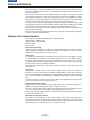
Thte lithium battery in this equipment must only be replaced by qualified personnel. When necessary, contact
your local Panasonic supplier.
“The lithium battery is a critical component (type number
CR2032 manufactured by Panasonic).
It must never be subjected to excessive heat or discharge. It must therefore only be fitted in equipment designed specifically for its use.
Replacement batteries must be of the same type and
manufacturer. They must be fitted in the same manner
and location as the original battery, with the correct polarity connections observed.
Do not attempt to re-cahrge the old battery or re-use it
for any other purpose. It should be disposed of in waste
products destined for burial rather than incineration.”
CAUTION
Danger of explosion if battery is incorrectly replaced.
Replace only with the same or equivalent type recommended by the equipment manufacturer. Discard used batteries according to manufacturer’s
instructions.
VARNING
Exposionsfara vid felaktigt batteribyte.
Använd samma batterityp eller en ekvivalent typ
som rekommenderas av apparattillverkaren. Kassera använt batteri enligt fabrikantens instruktion.
ADVARSEL!
Eksplosionsfare ved fejlagtig håndtering.
Udskiftning må kun ske med batteri af samme fabrikat og type. Levér det brugte batteri tilbage til leverandøren.
VAROITUS
Paristo voi räjähtää, jos se on virheellisesti asennettu.
Vaihda paristo ainoastaan laitevalmistajan suosittelemaan tyypiin. Hävitä käytetty paristo valmistajan ohjeiden mukaisesti.
is the safety information.
– 2 (E) –
CONTENTS
For your safety
Attention/Attentie
ÁBatteries are used for the main power source and memory back-up in the product.
At the end of their useful life, you should not throw them away.
Instead, hand them in as small chemical waste.
ÁVoor de primaire voeding en het reservegeheugen van het apparaat wordt gebruikgemaakt van een
batterij.
Wanneer de batterij is uitgeput, mag u deze niet gewoon weggooien, maar dient u deze als klein
chemisch afval weg te doen.
To remove the battery/Verwijderen van de batterij
Main Power Battery (Ni-cd Battery)
Batterij Voor Primaire Voeding (Nikkelcadmiumbatterij)
Anton/Bauer Battery
Anton/Bauer-Batterij
Battery/Batterij AU-BP402
Unlocking lever
Ontgrendelingshefboom
Battery/Batterij
AU-BP402
Battery/
Batterij
ÁIf a battery made by any other manufacturer is to be used, check the Operating Instructions accompanying the
battery.
ÁIn geval u een batterij van een anden fabrikant zou gebruiken, gelieve dan eerst zorgvuldig de gebruiksaan-wijzing van deze batterij te lezen.
Back-up Battery (Lithium Battery)
Batterij Voor Reservegeheugen (Lithiumbatterij)
ÁFor the removal of the battery for disposal at the end of
its service life, please consult your dealer.
ÁRaadpleeg uw leverancier over de verwijdering van de
batterij op het moment dat u het apparaat bij einde
levensduur afdankt.
Back-up Battery (Lithium Battery)
Batterij Voor Reservegeheugen (Lithiumbatterij)
– 3 (E) –
TOP MENU
CONTENTS
Contents
For your safety . . . . . . . . . . . . . . . . . . .
2
General and Features . . . . . . . . . . . . . .
6
ÁFeatures of the Camera Section . . . . .
6
ÁFeatures of the VTR Section . . . . . . .
9
System Configuration . . . . . . . . . . . . . . 10
Controls and Their Functions
ÁPower Supply Section . . . . . . . . . . . . . 11
ÁAccessory Mounting Section . . . . . . . 12
ÁAudio Function Section . . . . . . . . . . . . 13
ÁShooting (Recording)/Playback
Function Section . . . . . . . . . . . . . . . . . 15
ÁMenu Operation Section . . . . . . . . . . . 21
ÁTime Code-Related Section . . . . . . . . 21
ÁWarning/Status Display Section . . . . . 23
Power Supply
ÁUsing an Anton Bauer Battery
Pack . . . . . . . . . . . . . . . . . . . . . . . . . . 24
ÁUsing the Panasonic AU-BP402
Battery Pack . . . . . . . . . . . . . . . . . . . . 25
ÁUsing a Sony Battery Pack . . . . . . . . . 27
ÁUsing the Sony BP-90 Battery
Pack . . . . . . . . . . . . . . . . . . . . . . . . . . 28
ÁUsing the Sony BP-L60/BP-L90
lithium-ion Battery Pack . . . . . . . . . . . 28
ÁUsing an AC Power Supply (When
Using the AJ-B75 AC Adaptor) . . . . . . 29
ÁChecking and Selecting the Type of
Battery . . . . . . . . . . . . . . . . . . . . . . . . 030
Mounting the Lens . . . . . . . . . . . . . . . 31
Adjusting the Lens Flange . . . . . . . . . 32
Adjusting the White Shading . . . . . . . 33
Adjusting the Viewfinder
ÁAdjusting the Position . . . . . . . . . . . . . 35
ÁAdjusting the Diopter and
Screen . . . . . . . . . . . . . . . . . . . . . . . . 36
ÁAdjusting the Eyepiece Position . . . . . 36
ÁDetaching the Eyepiece . . . . . . . . . . . 37
ÁMounting the Viewfinder . . . . . . . . . . . 38
ÁDetaching the Viewfinder . . . . . . . . . . 38
Audio Input Preparations
ÁUsing the Microphone Mounted to the
Main Unit . . . . . . . . . . . . . . . . . . . . . . . 39
ÁUsing the AJ-MC700P Microphone Kit
(Option) Microphone Mounted to the
Main Unit . . . . . . . . . . . . . . . . . . . . . . . 39
ÁMounting the AJ-MH700P Microphone
Holder (Option) . . . . . . . . . . . . . . . . . . 40
ÁUsing the Microphone not Mounted to
the Main Unit . . . . . . . . . . . . . . . . . . . . 41
ÁConnecting an Audio Component . . . . 42
Mounting the Unit to a Tripod . . . . . . . . 43
Mounting the Shoulder Belt . . . . . . . . . . 44
Adjusting the Shoulder Pad Position . . . 45
Attaching the Rain Cover . . . . . . . . . . . 46
Connecting the AJ-EC3E Extension
Control Unit (Option) . . . . . . . . . . . . . 47
Displaying Menus on the Viewfinder Screen
ÁDisplaying the Setting Menu Inside the
Viewfinder . . . . . . . . . . . . . . . . . . . . . . 48
ÁSetting Menu Configuration . . . . . . . . 48
ÁChecking and Selecting the Master
Gain Setting . . . . . . . . . . . . . . . . . . . . 49
ÁChecking the DIAGNOSTIC Screen
Setting . . . . . . . . . . . . . . . . . . . . . . . . . 50
ÁTransferring to the MAIN menus and
SUB menus . . . . . . . . . . . . . . . . . . . . . 52
ÁBasic Setting Menu Operations . . . . . 53
Lamp Displays Inside the
Viewfinder . . . . . . . . . . . . . . . . . . . . . 56
ÁSetting the ! Lamp Display . . . . . . . . . 57
Status Displays Inside the Viewfinder
Screen . . . . . . . . . . . . . . . . . . . . . . . . 58
ÁSelecting Display Items. . . . . . . . . . . . 61
ÁDisplay Mode and Setting Change
Message . . . . . . . . . . . . . . . . . . . . . . . 62
ÁChanging the Display Mode . . . . . . . . 63
ÁSetting the Marker Displays . . . . . . . . 63
ÁSetting the Camera ID . . . . . . . . . . . . 64
Displays
ÁRemaining Battery Level and Audio
Level Displays . . . . . . . . . . . . . . . . . . . 65
ÁVTR Section Operation/
Status-Related Displays . . . . . . . . . . . 65
ÁTime Code-Related Displays . . . . . . . 66
Adjusting the Time and Date . . . . . . . . . 67
Adjustments and Setup During Recording
ÁAdjustments and Setup Using the
Setting Menu . . . . . . . . . . . . . . . . . . . . 68
ÁSetting the Gain Selector Value . . . . . 69
ÁSelecting Functions . . . . . . . . . . . . . . 70
Bold letters should be set or adjusted immediately after
purchase.
– 4 (E) –
TOP MENU
Contents
Adjusting the White Balance/Black Balance
ÁAdjusting the White Balance . . . . . . . . 71
ÁAdjusting the Black Balance . . . . . . . . 76
Setting the Electronic Shutter
ÁShutter Modes . . . . . . . . . . . . . . . . . . 78
ÁSetting the Shutter Mode/Speed . . . . . 79
ÁSetting the Synchro Scan Mode . . . . . 80
ÁChanging the Shutter Speed/Mode
Selection Range . . . . . . . . . . . . . . . . . 81
Changing the Iris Automatic Adjustment
Reference Value . . . . . . . . . . . . . . . . 81
Adjusting the Audio Level . . . . . . . . . . . 82
Setting the Time Data
ÁSetting the Time Code . . . . . . . . . . . . 84
ÁSetting the User Bit . . . . . . . . . . . . . . . 85
ÁLocking the Time Code to an External
Source . . . . . . . . . . . . . . . . . . . . . . . . 86
ÁExternal Lock Operation
Procedure . . . . . . . . . . . . . . . . . . . . . . 86
Using the user data . . . . . . . . . . . . . . . . 87
ÁUser data operation . . . . . . . . . . . . . . 87
ÁSaving the user data . . . . . . . . . . . . . . 87
ÁLoading the user data . . . . . . . . . . . . . 87
Setup Card Operations
ÁSetup Card Handling . . . . . . . . . . . . . 88
ÁSetup Card Data Operations . . . . . . . 89
Cassettes
ÁInserting and Ejecting Cassettes . . . . 94
ÁPreventing Accidental Erasure . . . . . . 95
Recording
ÁBasic Procedures . . . . . . . . . . . . . . . . 96
ÁSuccessive Shooting . . . . . . . . . . . . . 99
Playback—Checking Recorded Contents
ÁRec Review . . . . . . . . . . . . . . . . . . . . . 101
ÁColour Playback . . . . . . . . . . . . . . . . . 101
Connection With an External VTR. . . . . 102
Recording Simultaneously with the
Internal VTR and an External
VTR . . . . . . . . . . . . . . . . . . . . . . . . . . 103
Recording With an External VTR Instead
of the Internal VTR
ÁUsing the 26-pin/12-pin Output
Adaptor . . . . . . . . . . . . . . . . . . . . . . . . 105
RET Button . . . . . . . . . . . . . . . . . . . . . . 107
Replacing the Backup Battery . . . . . . . . 108
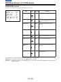
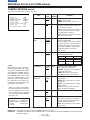
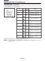
Setting Menu Screens . . . . . . . . . . . . . . 109
ÁMAIN menus . . . . . . . . . . . . . . . . . . . . 109
ÁMAIN menu screen 1 of 4
(SUB menus) . . . . . . . . . . . . . . . . . . . 113
ROP (113), MATRIX (114), LOW SETTING (115), MID
SETTING (116), HIGH SETTING (117), ADDITIONAL DTL
(118), SKIN TONE DTL (119), KNEE/LEVEL (120), FLARE/
GAMMA (121), CAMERA SETTING (121)
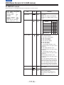
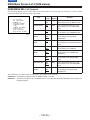
ÁMAIN menu screen 2 of 4
(SUB menus) . . . . . . . . . . . . . . . . . . . 122
VF DISPLAY (122), VF INDICATOR (124), CAMERA ID
(125), SHUTTER SPEED (125), SYNCHRO SCAN (126),
!LED (126), CAMERA SW MODE (127), SUPER GAIN
(128), VTR FUNCTION (129), BATT/TAPE ALARM (131)
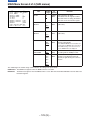
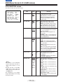
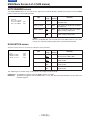
ÁMAIN menu screen 3 of 4
(SUB menus) . . . . . . . . . . . . . . . . . . . 132
CARD READ/WRITE (132), CARD R/W SELECT (133),
REC (ASPECT)/PB/RET (134), MIC/AUDIO (135),
GENLOCK/IRIS (137), VIDEO OUT (138), TIME/DATE
(138), LENS SEL/ADJ (138)
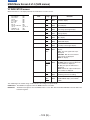
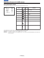
ÁMAIN menu screen 4 of 4
(SUB menus) . . . . . . . . . . . . . . . . . . . 139
USER MENU SEL 1 of 3 (139), USER MENU SEL 2 of 3
(140), USER MENU SEL 3 of 3 (141), AUTO SHADING
(142), EVALUATION (142), INITIALIZE (147),
DIAGNOSTIC (147)
ÁREMOTE menu screen . . . . . . . . . . . . 148
REMOTE FUNCTION (148), VF IND. (REMOTE) (148),
!LED (REMOTE) (149), TALLY/RET (REMOTE) (149)
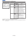
Warning System . . . . . . . . . . . . . . . . . .
Emergency eject . . . . . . . . . . . . . . . . . .
Error Codes . . . . . . . . . . . . . . . . . . . . . .
Maintenance
ÁCondensation . . . . . . . . . . . . . . . . . . .
ÁCleaning the Video Heads . . . . . . . . .
ÁCleaning the Viewfinder . . . . . . . . . . .
ÁCharacteristic Phenomenon of CCD
Cameras . . . . . . . . . . . . . . . . . . . . . . .
Inspections Before Shooting
ÁInspection Preparations . . . . . . . . . . .
ÁInspecting the Camera Section . . . . . .
ÁInspecting the Viewfinder . . . . . . . . . .
ÁInspecting the Iris and Zoom
Functions . . . . . . . . . . . . . . . . . . . . . .
ÁInspecting the VTR Section . . . . . . . .
Specifications
ÁGeneral . . . . . . . . . . . . . . . . . . . . . . . .
ÁCamera Section . . . . . . . . . . . . . . . . .
ÁViewfinder . . . . . . . . . . . . . . . . . . . . . .
ÁVTR Section . . . . . . . . . . . . . . . . . . . .
ÁAccessories . . . . . . . . . . . . . . . . . . . .
ÁRelated Components . . . . . . . . . . . . .
– 5 (E) –
150
152
152
153
153
153
153
154
154
155
156
156
158
158
158
159
159
160
CONTENTS
General and Features
This unit combines as a single integrated unit a 3-CCD colour video camera which features ITCCDs and a 600,000-pixel on-chip lens, and a DVCPRO format VTR which incorporates compression technology.
Not only can the screen aspect ratio be switched between 16:9 and 4:3 in a single action but the
rate at which the signals are recorded onto the VTR tape can also be set to 50 Mbps for a higher
picture quality or 25 Mbps for a longer recording duration. Recording at the 50 Mbps rate enables
pictures with a very high picture quality to be recorded: this means that this is an integrated VTR
unit which provides all the optimum functions and performance for EFP applications.
The unit in itself is compact and lightweight, its power consumption is minimal, it yields a high
picture quality, and it offers excellent sensitivity, mobility and dust-proof and damp-proof capability. These features make it possible for the unit to be used in ENG applications as well.
Both the camera unit and VTR unit feature digital signal processing to achieve much higher levels
of picture quality and stability.
Memory cards complying with global standards can be used for the camera and VTR setting data
to provide a system to manage the data.
Features of the Camera Section
The camera section of the AJ-D910WB has the following features.
ÁHigh sensitivity: 2000 lux (F13)
ÁHigh S/N ratio: 61 dB (standard)
ÁUltra-low smear
ÁUltra-low flare
Digital signal processing
Signal processing is digitized by a 18 MHz (typ.) 10-bit AD/DA converter. This improves picture
quality, stability and reliability, and allows the viewfinder screen displays as well as numerous
adjustment and setup items to be converted to menus.
Setting menu
The setting menu is displayed on the viewfinder screen, and controls the status displays, messages, marker displays, etc. Whether or not to display each item, as well as the display conditions
when items are to be displayed, can be selected according to the user’s convenience. For example, display ON/OFF for the ! lamp display which informs the user that the unit has entered irregular status can be selected for 8 different conditions.
The setting menu is also used to select various settings and functions and execute memory card
operations, etc.
Setup cards
Setting menu and subject data can be stored on SRAM memory cards with a capacity of
64 kilobytes or greater which conform to PCMCIA standard ratings as setup cards. Stored data
can be saved individually or according to the shooting conditions, allowing the same setup conditions to be easily reproduced and assisting in standardizing setup conditions between individual
data.
An ATA flash memory card with a memory size of 4 MB or more is required to operate the Picture
Link (Pix Link) function sold as an optional accessory.
High-function electronic shutter
Using the built-in electronic shutter achieves steady images even of quickly moving subjects. In
addition, the following special operation modes can also be selected.
ÁSynchro scan mode: This mode is suited for shooting personal computer and workstation monitor screens (50.6–248 Hz), and provides images with little horizontal stripe noise.
ÁHigh vertical resolution (Super V) mode: This mode provides images with high vertical resolution
compared to standard mode.
Wide range of video gain selections
Gain values can be selected from p3 dB to o30 dB using the setting menu and the GAIN switch.
The high S/N ratio allows images with little noise to be obtained even when the gain is increased
for shooting in dark locations. Using the SUPER GAIN switch provided specially to implement the
super gain function, the video gain can be set to 30, 36, 43 or 46 dB.
– 6 (E) –
CONTENTS
Features
Automatic adjustment and memory functions for black balance/white balance
The black set, black balance and white balance can be automatically adjusted by simple switch
operations. Adjustment values are held in the memory even if the power for the unit is turned off,
so there is no need to readjust the balance each time the power is turned on.
There are two memory systems for white balance which can hold 3 adjustment values each for the
CC filter (cross filter is the same as 3200K.), making a total of 6 adjustment values. When adjustment values matching the illumination conditions are selected from among the values stored in the
memory, the unit is automatically adjusted to the corresponding white balance. (A menu setting
also allows adjustment of only two values instead of the values for each filter.) In addition, when
the unit is shipped from the factory, the white balance value for 3200K is stored in the memory as
a preset value. This value can be called when there is no time to adjust the white balance, etc.
Character display function
The unit is equipped with a function that displays switch settings, the automatic adjustment status
for black balance and white balance, warning displays, etc. on the viewfinder screen.
In addition, when using an Anton Bauer Digital Magnum series battery as the unit’s power supply,
the remaining battery level can be displayed numerically on the viewfinder screen.
Warning system for displaying the VTR section status
The unit informs of VTR trouble, the end of the tape, battery wear, etc. with various warning lamps
and a warning tone. The remaining tape time can also be checked by the character display inside
the viewfinder.
4·2 filters as standard equipment
CC (colour temperature conversion) and ND (neutral density) filters are provided as standard
equipment. The filter setting best suited to the brightness of the subject and lighting conditions can
be selected from among 16 different combinations.
Fine adjustment of the automatic iris reference value
The reference value for automatic iris adjustment can be finely adjusted by setting menu operations.
Auto close function
The unit is equipped with an auto close function which automatically closes the lens in the following cases.
ÁWhen the black balance is automatically adjusted.
ÁWhen the power is turned off in the auto iris mode.
Generation of standard colour bar and reference audio signals
The camera section contains a circuit which generates a standard colour bar signal to facilitate
colour monitor adjustments, and a circuit which generates a reference level audio signal to facilitate audio level adjustments.
Functions and circuits for assuring high picture quality
The AJ-D910WB is equipped with the following functions (and circuits) in order to assure high
picture quality and is designed to make the fullest use of the advantages of the high-performance
CCD.
ÁA built-in AUTO KNEE circuit achieves a wide dynamic range which allows large signals to pass
through.
ÁA built-in 2-line image enhancer
ÁA built-in shading compensation function for use with a lens extender
ÁA built-in sawtooth wave generator for adjustments
ÁA zebra pattern ON/OFF selector switch which selects three types of zebra patterns including
spot zebra from two levels of zebra patterns.
– 7 (E) –
CONTENTS
Features
Audio functions
ÁA phantom power supply type super-cardioid microphone (option) can be attached and it can
also be detached from the main unit for use in interviews.
ÁMicrophone can also be connected, and can be attached to the main unit using the
AJ-MH700P microphone holder (option).
ÁThe audio CH1 recording level can be easily adjusted at the front panel of the unit.
Recording by an external VTR
When an external VTR is connected using the 26-pin/12-pin output adaptor (option,
AJ-YA900P), recording can be performed by the external VTR instead of the internal VTR.
Remote control
Connecting the Extension Control Unit (option, AJ-EC3E) allows a portion of the camera section
functions to be operated by remote control.
– 8 (E) –
CONTENTS
Features
Features of the VTR section
Digital system
The VTR section features a component digital recording system that employs the latest compression technology and non-compressed PCM recording for audio. This system provides superior S/
N, frequency band and waveform characteristics as well as reproduction of detailed areas, etc.,
and realizes even higher picture and sound quality.
One of the following 4 modes can be selected for conducting recording and playback: 16:9
(50 Mbps), 4:3 (50 Mbps), 16:9 (25 Mbps) and 4:3 (25 Mbps).
Rec review function
By automatically rewinding and playing back the last two to ten seconds or so of the recording,
this function enables what has been recorded to be promptly checked out.
Playback function
This function enables the playback picture (black-and-white picture) to be seen on the viewfinder
screen. In addition, colour playback pictures can be output from the unit’s VIDEO OUT connector.
Built-in time code generator/reader
Time code information can be recorded and played back on a dedicated subcode track.
Locking of the time code to an external source
The built-in time code generator can be locked to an external generator. Also, the built-in time
code generator uses a lithium battery as its back-up power supply, allowing time codes to be
backed up for approximately one year even if power is not supplied to the unit.
Built-in DOLBY NR SystemF
A Dolby B Noise Reduction System is built in for audio recording in the longitudinal direction.
Successive shooting
Images can be shot successively within an accuracy of 0–o1 frame simply by pressing the VTR
START button or the lens VTR button.
FDolby noise reduction manufactured under license from Dolby Laboratories Licensing Corporation.
“Dolby” and the double-D symbol are trademarks of Dolby Laboratories Licensing Corporation.
– 9 (E) –
CONTENTS
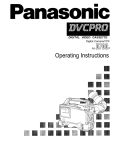
System Configuration
Microphone kit
AJ-MC700P
Shoulder
belt
1.5½ viewfinder
AJ-VF10E/-VF15E
2.0½ viewfinder
AJ-VF20WE
26P/12P
output
adaptor
AJ-YA900P
Battery case
SHAN-B220
Microphone holder
AJ-MH700P
VTR cable
VTR
Multi connector
cable
SHAN-C12TCA
Panasonic Battery
AU-BP220
Sony Battery NP-1
IDX Battery L-40
Battery case
AU-M402H
Lens
(Bayonet type)
Fujinon/Canon
Panasonic Battery
AU-BP402
Anton Bauer Battery
5w EVF mount
adaptor
AJ-QVF900
5w EVF AJ-VF53E
Camera/VTR
AJ-D910WB
Battery case/
Battery holder
Sony Battery
BP-90
BP-L60/BP-L90
AC adaptor
AJ-B75
5w EVF mount
adaptor
AJ-YA711
5w EVF
WV-VF65B/C
Rain cover
SHAN-RC700
Soft carrying
case
AJ-SC900
Tripot mount
adaptor
SHAN-TM700
Cassette tape
ÁM size cassette tape
exclusively for
DVCPRO
Cleaning tape
AJ-CL12MP
Setup memory card
SHL-064HSRVS
Picture Link adaptor
board
AJ-YAP900
Extension control
unit AJ-EC3E
Carrying case
AJ-HT900
FAJ-YA711/WV-VF65B/C are not available in European market. For further details, consult with your dealer.
– 10 (E) –
Battery
charger
AG-B425
CONTENTS
Controls and Their Functions
1
4
2
3
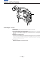
Power Supply Section
e Battery holder
The battery pack (option) made by Anton Bauer is mounted onto this holder.
f DC IN (external power input) connector (XLR, 4P)
The AJ-B75 AC adaptor (option) is plugged into this socket when the unit is to be operated by
AC power. An external battery is plugged in when an external battery is to be used to operate
the unit.
g BREAKER (circuit breaker) button
In order to protect the equipment, the circuit breaker is tripped and the power is automatically
turned off when an excessively high level of power flows inside. Upon completion of the internal
inspection and adjustments, push this button back in. The power will come back on provided
that there is no trouble inside the unit.
h POWER switch
ON: Set to this position to turn on the unit’s power.
OFF: Set to this position to turn off the unit’s power.
– 11 (E) –
CONTENTS
Controls and Their Functions
6
5
5
7
9
8
n
q
Knob
(included)
s
p
o
r
Screw
(included)
The accessory
control knob can be
attached to the
AUDIO LEVEL CH1
control.
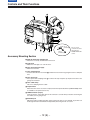
Accessory Mounting Section
i Hook for mounting shoulder belt
Attach the accessory shoulder belt to this hook.
j Light shoe
Mount the video light, etc. onto this shoe.
k Lens mount (bayonet type)
Mount the lens here.
l Lens clamping lever
Insert the lens into the lens mount k, and turn the lens mount ring using this lever to clamp the
lens.
m Lens mount cap
Press up the lens clamping lever l to remove this cap. Keep the cap in place if the lens is not
going to be mounted.
n Lens cable clamp
This is for clamping the lens cable.
o Tripod mount
When the unit is to be secured to a tripod, mount the tripod attachment (SHAN-TM700) which
is available as an optional accessory.
p LENS connector (12-pin)
Hook up the lens connecting cable to this connector. Consult with your dealer concerning the
lens which you are going to use.
q Shoulder pad
Adjust this pad to facilitate operation when carrying the unit on your shoulder. Its position can
be brought forward or backward and adjusted by loosening the two set screws.
– 12 (E) –
CONTENTS
Controls and Their Functions
t
u
v
w
x
{
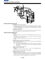
Audio Function Section (1)
y
z
r AUDIO LEVEL CH1 (audio channel 1 recording level) control
When the AUDIO SELECT CH1/CH2 switch u is set to MAN, the recording level of audio
channel 1 can be adjusted by this control in addition to the AUDIO LEVEL CH1 control t on
the side panel.
s MIC IN (microphone input) jack (XLR, 3-pin)
Connect an optional microphone to this jack. The power for the microphone is supplied from
this jack.
t AUDIO LEVEL CH1/CH2 (audio channel 1/2 recording level) controls
When the AUDIO SELECT CH1/CH2 switch u is set to MAN, the audio level of audio channels
1 and 2 can be adjusted using these controls.
However, the audio CH1 level can also be adjusted using the AUDIO LEVEL CH1 control r on
the front panel.
u AUDIO SELECT CH1/CH2 switch (audio channel 1/2 auto/manual level adjustment selector) switch
This selects the method used to adjust the audio levels of audio channels 1 and 2.
AUTO: For adjusting the levels automatically.
MAN: For adjusting the levels manually.
v AUDIO IN (audio input selector) switch
This selects the input signals to be recorded on audio channels 1 and 2.
FRONT [MIC]: The microphone input signals connected to the MIC IN jack s are recorded.
REAR [MIC]: The microphone input signals connected to the AUDIO IN CH1/CH2 connectors y are recorded.
REAR [LINE]: The line input signals connected to the AUDIO IN CH1/CH2 connectors y
are recorded.
w REAR MIC POWER switch
ON: The phantom power is supplied to the rear microphone.
OFF: The phantom power is not supplied to the rear microphone.
x CUE switch
CH1: The audio CH1 signals are recorded on the cue track.
1/2:
The signals of audio CH1 and CH2 are mixed together and recorded on the cue track.
CH2: The audio CH2 signals are recorded on the cue track.
y AUDIO IN CH1/CH2 (audio input channel 1/2) connectors (XLR, 3P)
An audio component or microphone is connected here.
z AUDIO OUT connector (XLR, 3P)
This is connected to an audio component. The audio channels are coupled to the MONITOR
SELECT switch and switched in tandem.
{ DC OUT (DC power output) connector
This is the DC 12 V output connector. A current of approximately 100 mA can be taken out.
– 13 (E) –
CONTENTS
Controls and Their Functions
´
®
™
ß
|
}
~
Audio Function Section (2)
†
| ALARM (warning tone volume) control
This adjusts the warning tone volume heard from the speaker ~ or the earphone connected to
the PHONES jack ¡. When it is set to the lowest position, the warning tone is not audible.
However, by making changes to the inside parts, the tone can be made audible even when the
control is at its lowest position.
} MONITOR (volume) control
This adjusts the volume of the sound other than the warning tone—the sound from the speaker
~ or earphone ¡. When it is set to the lowest position, no sound is heard.
Audio Function Section (3)
~ Speaker
During recording, the EE sound can be monitored; during playback, the playback sound can be
monitored.
The warning tone is heard through the speaker in synchronization with the flashing or lighting
of the warning lamp and warning display.
The speaker sound is automatically muted when an earphone is connected to the PHONES
jack ¡.
MONITOR SELECT (audio channel selector) switch
This selects the audio channel whose sound is to be heard through the speaker ~ AUDIO
OUT connector z, or earphone.
CH1: The audio channel 1 sound is output.
1/2:
The sound produced by mixing the audio channel 1 and 2 sound or the stereo sound is
output. However, only the mixed sound is output from the speaker ~ and AUDIO OUT
connector z.
CH2: The audio channel 2 sound is output.
MONITOR (sound selector) switch
This selects the sound of the earphone when 1/2 is selected with the MONITOR SELECT
switch .
ST: The stereo sound of audio channels 1 and 2 is output.
MIX: The mixed sound of audio channels 1 and 2 is output.
¡ PHONES (earphone) jack (mini-jack)
When an earphone (option) is connected to this jack, the sound selected by the MONITOR
switch can be heard. The warning tones relating to the unit’s operation or status can also be
heard. An earphone enabling a sufficiently high volume of sound to be heard is recommended.
When the earphone is connected, speaker ~ sound is automatically muted.
– 14 (E) –
CONTENTS
Controls and Their Functions
©
¢
£
§ ¶
•
(The viewfinder shown in the illustration is the AJ-VF10E.)
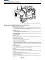
Shooting (Recording)/Playback Function Section (1)
¢ Viewfinder (optional accessory)
Black-and-white images can be seen in the viewfinder during recording and playback. Warnings and messages relating to the unit’s operating status and settings, zebra pattern, markers
(safety zone marker, centre marker), etc. can also be seen.
£ PEAKING control
This is used to adjust the contours of the images inside the viewfinder to facilitate focusing. It
does not affect the camera’s output signals.
¤ CONTRAST control
This is used to adjust the contrast of the screen inside the viewfinder. It does not affect the
camera’s output signals.
¥ BRIGHT control
This is used to adjust the brightness of the screen inside the viewfinder. It does not affect the
camera’s output signals.
¦ ZEBRA (zebra pattern) switch
This displays the zebra pattern inside the viewfinder.
ON: The zebra pattern is displayed.
OFF: The zebra pattern is not displayed.
When the unit is shipped from the factory, the zebra pattern is set in such a way that those
parts with an IRE video level from approx. 70% to 85% are displayed. The displaying of parts
with a level ranging from 50% to 110% or more or with a certain level can also be set on the
setting menu.
§ Diopter control knob
This is adjusted in such a way that the images on the viewfinder screen are seen most clearly
in accordance with the dioptric power of the camera’s operator.
¨ Eyepiece
© Viewfinder forward-backward/left-right position clamp lever
Loosen this lever to adjust the position of the viewfinder ¢ in the forward-backward or left-right
direction.
ª Eyepiece forward-backward movement ring
Turn this ring to adjust the position of the eyepiece ¨ in the forward-backward direction.
« Viewfinder stopper screw
To detach the viewfinder ¢ from the camera, loosen this screw and then detach the viewfinder.
– 15 (E) –
CONTENTS
Controls and Their Functions
¨
≠
(The viewfinder shown in the
illustration is the AJ-VF10E.)
Æ
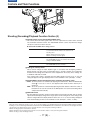
Shooting (Recording)/Playback Function Section (2)
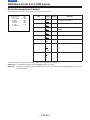
¬ CC/ND FILTER (filter selector) knob
This selects the filter to match the light source which is illuminating the subject.
If the setting of this knob is changed when the menu display mode has been set to “3”, the new
setting will appear on the setting change message display area of the viewfinder screen.
È The knob and filter settings are listed below.
Filter
Description
knob setting
Example of filter setting to match shooting conditions
A
Cross
For setting the light source into the shape of a cross.
B
3200K
Dawn, dusk, inside a studio
C
4300K
Outdoors under a clear sky, outdoors in the rain
D
6300K
At the beach, in mountains covered with snow
1
Clear
Indoors, studios, dark places
2
1/4ND
Outdoors under a cloudy sky
3
1/16ND
Outdoors under a clear sky
4
1/64ND
Outdoors, at the beach or in mountains covered with snow in summer
Synchro scan adjustment switches
These switches are used to adjust the synchro scan speed. Pressing the “p” switch reduces
the shutter speed; pressing the “o” switch increases the shutter speed. Set these switches to a
position where the side bar noise in the viewfinder is eliminated during personal computer
monitor shooting, etc.
|Note{
When these switches are used for UB/TC/CTL settings while the SET position has been selected as the TCG switch position, they will not serve their function as synchro scan adjustment
switches. The TCG switch must be set to F-RUN or R-RUN for these switches to serve their
function.
® WHITE BAL (white balance memory selector) switch
PRST: Set to this position when there is no time to adjust the white balance. The white balance value for 3200K is stored in the memory.
A or B: When the AUTO W/B BAL switch ± is pressed to the AWB side, the white balance
is automatically adjusted in accordance with the setting position of the filter knob ¬,
and the adjustment value is stored in memory A or memory B.
When the FILTER knob and the WHITE BAL switch are set to the same positions as the ones
set when the adjustment was made, the adjustment value stored in the memory is called, and
the unit is automatically adjusted to the white balance which corresponds to this value.
If the setting of this switch is changed when the menu display mode has been set to “3”, the
new setting will appear at the WHITE BAL switch display position on the viewfinder screen.
(Example: “A”)
– 16 (E) –
CONTENTS
Controls and Their Functions
≤
±
∞Ø
Shooting (Recording)/Playback Function Section (3)
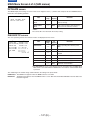
¯ OUTPUT (output signal selector)/AUTO KNEE switch
This switch selects the video signals which are to be output from the camera unit to the VTR
unit, viewfinder and video monitor. The AUTO KNEE function can be used when the images
shot by the camera have been selected.
È OUTPUT/AUTO KNEE switch setting positions
BARS
Colour bar signals are output. The AUTO KNEE circuit
is not activated. Set the switch to this position in the
following cases:
ÁWhen adjusting the video monitor
ÁWhen recording colour bar signals
CAM, AUTO KNEE OFF
The images shot by the camera are output.
The AUTO KNEE circuit is not activated. The default
setting is “MANUAL KNEE”.
CAM, AUTO KNEE ON
The images shot by the camera are output.
The AUTO KNEE circuit is activated.
° GAIN (gain selector) switch
This is used to change the video amplifier’s gain in accordance with the lighting conditions
during shooting. The gain values corresponding to the L, M and H settings are assigned beforehand on the setting menu. When the unit is shipped from the factory, these settings are:
Lr0 dB, Mr9 dB and Hr18 dB.
If the setting of this switch is changed when the display mode has been set to “3”, the new
setting will appear at the gain display position on the viewfinder screen. (Example: “12 dB”)
± AUTO W/B BAL (white balance/black balance automatic adjustment) switch
AWB: Set to this position for automatically adjusting the white balance. When the WHITE BAL
switch ® is now set to “A or B”, the adjusted value will be stored in memory A or
memory B.
ABB: Set to this position for automatically adjusting the black balance. When this switch is
held down for at least 10 seconds at the ABB position, the auto black shading will be
compensated automatically.
² SHUTTER switch
Set this to ON when using the electronic shutter. When it is pressed to the SEL side, the shutter
speed and mode displays change in the ranges preset on the setting menu. If the setting of this
switch is changed when the display mode has been set to “2” or “3”, the new setting will appear
at the shutter display position on the viewfinder screen. (Example: “:1/248”, “:1/50.6”)
1) AUTO KNEE function
When the level is adjusted to people, scenes, etc. for shooting against a very bright background, the background will be whited out and the
buildings or scenes in the background will become blurred. If the AUTO KNEE function is activated in cases like these, the background can be
reproduced in clear detail. This function is especially effective for shooting in the following conditions:
ÁWhen shooting people in shade under a clear sky
ÁWhen simultaneously shooting people in vehicles or indoor and the outdoor scenery seen through the windows
ÁWhen shooting scenes with a high contrast
– 17 (E) –
CONTENTS
Controls and Their Functions
µ
∂
¥
³ ECU REMOTE (remote control) connector (6-pin)
Connect the AJ-EC3E extension control unit (option) here.
|Note{
The POWER switches on unit and extension control unit must be set to OFF before the remote
control cable is connected or disconnected.
´ 26-pin/12-pin output adaptor (See page 105 for mounting method.)
The 26-pin/12-pin output adaptor AJ-YA900P (option) is mounted on this section. When the
portable VTR is connected as the external VTR, recording can be performed simultaneously
with the unit’s built-in VTR.
Furthermore, by connecting the SHAN-C12TCA multi-connector cable (optional accessory) to
the 12-pin connector, it is possible to output the sound of audio channels 1 and 2 separately.
µ VIDEO OUT connector (BNC)
This outputs the video signals (75° termination, rated level) to be monitored. During recording,
EE images can be monitored; during playback, playback images can be monitored.
While performing settings on the menu, the setting menu can be superimposed onto the shot
images appearing on the monitor screen so that the settings can also be checked.
¶ CAM OUT (camera output) connector (BNC)
This outputs the composite video signals (75° termination, rated level). When a video monitor
is connected, the images shot by the camera can be monitored. Even while the VTR is playing
back, the camera’s images are output at all times.
– 18 (E) –
CONTENTS
Controls and Their Functions
≥
∑
∏
π
∫ ª
Shooting (Recording)/Playback Function Section (4)
· VTR START button
When this pressed, recording commences; when it is pressed again, recording stops. This
button has the same function as the VTR button on the lens side.
¸ VTR SAVE/STBY (tape protection) switch
This selects the power supply status while the VTR recording is temporarily stopped (REC
PAUSE).
SAVE: This is the tape protection mode. The cylinder is stopped in the half-loading status.
Compared with the STBY position, less power is consumed and the unit can be
operated longer using the battery. It takes longer for recording to commence after
the VTR START button · is pressed in the SAVE position than in the STBY position.
When the switch is set to this position, the VTR SAVE lamp inside the viewfinder
lights.
STBY: Recording commences immediately when the VTR START button is pressed.
|Note{
This unit will automatically go into SAVE mode when the designated time for standby (STBY)
condition is exceeded. To return to standby mode, press the VTR SAVE/STBY switch once to
select SAVE mode, then once again to return to STBY mode.
¹ MODE CHECK button
While this button is kept depressed, the camera’s setting status is displayed in the viewfinder. It
does not affect the camera’s output signals.
º SUPER GAIN button (inside sliding cover)
The super gain mode is forcibly established when this button is pressed, and each time the
button is pressed when all the super gain values have been set using “SUPER GAIN” on the
MAIN menu 2 of 4 screen, the gain is switched by one level in the following sequence: 30 dB>
36 dB>43 dB>46 dB>OFF>30 dB, etc. However, the DTL and other menu settings cannot
be performed.
» SUPER IRIS button (inside sliding cover)
This is used when backlight compensation (or the super black functionF1) is to be provided.
When it is pressed, the switch settings are displayed inside the viewfinder for 3 seconds. When
it is pressed again, backlight compensation (or the super black functionF1) is released.
F1See MAIN menu screen 2 of 4 on page 127 for details on the super black function.
Super gain: When 30 dB is allotted to the SUPER IRIS button, DTL and other menu settings cannot be performed for this
30 dB.
– 19 (E) –
CONTENTS
Controls and Their Functions
¿¡ Ω
ø
æ
…
¬
¼ MARK button
This is used when the Picture Link (Pix Link)F1 function is to be used. Each time it is pressed M1
(MARK1), M2 (MARK2) or no display appears in the viewfinder.
F1Picture Link adaptor board (AJ-YAP900) is sold as an option.
½ EJECT (cassette eject) button
Press this to insert or eject the cassette.
¾ REW (rewind) button
Press this to rewind the tape. Its lamp lights during rewinding.
If this button is pressed during playback, the playback images are rewound at approximately
quadruple speed while the button is held down.
¿ FF (fast forward) button
Press this to fast forward the tape. Its lamp lights during fast forwarding.
If this button is pressed during playback, the playback images are fast forwarded at approximately quadruple speed while the button is held down.
À PLAY/PAUSE button
Press this to view the playback images on the viewfinder screen or colour video monitor. Its
lamp lights during playback.
If this button is pressed again during playback, playback is paused and the lamp goes off. After
playback has been paused for 2 minutes, the unit automatically switches to stop status
(STOP).
Á STOP button
Press this to stop the tape travel.
 EMERGENCY screw (inside the rubber cap)
For details, refer to the “emergency eject” function (on page 152).
– 20 (E) –
CONTENTS
Controls and Their Functions
»
√
≈ ∆« ƒ
º
Menu Operation Section
à Setup card insertion slot
The optional setup cards are inserted into this slot.
Ä MENU SET/OFF switch
This displays the setting menu on the viewfinder screen through VIDEO OUT connector.
SET: The page on which the previous setting menu operations were completed appears on
the viewfinder screen. (When the menu is used for the first time, the first of the pages
which can be displayed appears.)
OFF: The setting menu is not displayed on the viewfinder screen through VIDEO OUT connector.
Å SHIFT/ITEM button
Each time this button is pressed, the cursor moves on the setting menu page now displayed.
Use it when selecting items.
|Note{
This switch functions differently depending on the operation item. Check the function by operating the menu item by item.
Æ UP button
This is used to increment the setting of the item selected on the setting menu by 1 level each
time it is pressed or to switch the setting between ON and OFF.
Ç DOWN button
This is used to decrement the setting of the item selected on the setting menu by 1 level each
time it is pressed or to switch the setting between ON and OFF.
È PAGE button
This is used to select the setting menu page.
Time Code-Related Section (1)
É GENLOCK IN/(VIDEO IN) connector (BNC)
The reference signal is supplied to this connector when the camera section is to be subject to
genlock operation or when the time code is to be locked externally.
– 21 (E) –
CONTENTS
Controls and Their Functions
À Ê TC IN connector (BNC):
The time code serving as the reference is input when the time code is locked to an external
source.
Ë TC OUT connector (BNC):
Connect this to the time code TC IN connector on the external VTR when locking the external
VTR’s time code to this unit’s time code.
Time Code-Related Section (2)
Ì HOLD button
The time data appearing on the counter display at the instant when this button is pressed is
held. (The time code generator will still continue to run.) When the button is pressed again, the
hold status is released. Use the button to ascertain the time at which a particular scene was
shot, for example.
Í RESET button
This resets the time data on the counter display to “00:00:00:00”. When the TCG switch Ñ is
set to SET and this button is pressed, the time code or user’s bit can be reset to “00:00:00:00”
or “00 00 00 00”.
Î DISPLAY switch
The time code, CTL or user’s bit is made to appear on the counter display depending on the
setting positions of this switch and the TCG switch Ñ.
UB: The user’s bit is displayed.
TC: The time code is displayed.
CTL: CTL is displayed.
Ï UP button, DOWN button
When setting the time code or user’s bit, these buttons increment or decrement by 1 the figure
of the digit made to flash by the SHIFT/ITEM button Ð.
Ð SHIFT/ITEM (digit advance) button
When setting the time code or user’s bit, this button is used to cause the digit which is to be set
to flash.
– 22 (E) –
CONTENTS
Controls and Their Functions
Ã
Õ
Œ
‘
’
“
÷
◊
ÿ
—
”
– œœ
(The viewfinder shown in the illustration is the AJ-VF10E.)
Ñ TCG (time code selector) switch
This is used to set the running mode of the internal time code generator.
F-RUN: This position is used when the time code is to be advanced continuously regardless of
the VTR’s operation.
Set to this position when aligning the time code with the actual time or locking the time
code to an external source.
SET:
This position is used for setting the time code or user’s bit.
R-RUN: This position is used when the time code is to be advanced only while recording is in
progress. The time code will be recorded continuously on a tape with a succession of
unedited shots.
Warning/Status Display Section
Ò Tally lamp
This is activated when the TALLY switch Ó is at HIGH or LOW, and it lights during recording by
the VTR section. It flashes in the same way as the REC lamp inside the viewfinder to warn the
operator. The brightness when lit can be selected using the TALLY switch (HIGH or LOW).
Ó TALLY switch
This controls the tally lamp Ò.
HIGH: The tally lamp is made brighter.
OFF: The tally lamp is extinguished.
LOW: The tally lamp is made darker.
Ô Back tally lamp
This functions in the same way as the tally lamp Ò when the back tally switch Õ is set to ON.
Õ Back tally switch
This controls the back tally lamp Ô.
ON: The back tally lamp operates.
OFF: The back tally lamp does not operate.
Ö WARNING lamp
This flashes or lights when trouble occurs in the VTR section.
× LIGHT switch
ON: This illuminates the display window Ø.
OFF: This extinguishes the display window illumination.
Ø Display window
The warnings related to the VTR section, remaining battery level, sound level, time data, etc.
are displayed in this window.
– 23 (E) –
CONTENTS
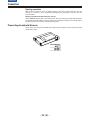
Power Supply
Power can be supplied to the unit using a battery pack or AC power supply.
Using a battery pack
A battery pack which is made by any of the four following manufacturers can be used:
A Panasonic, B Anton Bauer, C Sony or D IDX.
Before using a battery pack, be sure to charge it completely using a battery charger.
ÁSee the Handling Instructions for the battery pack and battery charger for a detailed explanation
of charging methods.
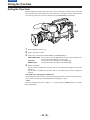
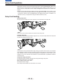
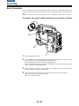
Using an Anton Bauer Battery Pack
1
Mount the battery pack.
Insert the battery pack in the direction of the arrow and then slide it into place.
Power Supply Output Connector
Control Switch
2
When detaching the battery, hold down the detachment lever of the battery holder and slide
the battery pack in the direction of the arrow.
Lever
Pack
|Note{
The AJ-D910WB supports the intelligent battery system and the ultra-light system.
Automatic detection can be performed for intelligent batteries with a remaining battery level of
10% or more. At this time, the remaining battery level is displayed numerically (percentage
display) inside the viewfinder. If the power is turned on with a remaining battery level of 10%
or less, the voltage is displayed. When external power is supplied after intelligent battery
sensing, the remaining battery charge display switches to the externally supplied voltage
display.
– 24 (E) –
CONTENTS
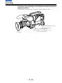
Power Supply
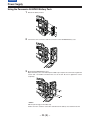
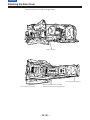
Using the Panasonic AU-BP402 Battery Pack
1
Detach the battery mounts.
2
Connect the unit’s connectors with the connectors of the AU-M402H battery case.
3
Mount the AU-M402H battery case.
Open the battery case cover and lift up the rubber cap to expose the screw holes. Tighten the
screws with a screwdriver and mount the case to the unit. Be sure to tighten the screws
completely.
|Notes{
ÁDo not pull strongly on the rubber cap.
ÁTake care not to catch the connection cord between the battery case and the main unit.
– 25 (E) –
CONTENTS
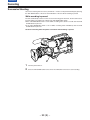
Power Supply
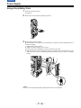
4
Connect the battery pack plug to the connector inside the case and insert the battery pack.
|Note{
The unit’s power must be set to OFF before the plug is inserted or removed.
– 26 (E) –
CONTENTS
Power Supply
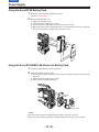
Using a Sony Battery Pack
1
2
3
Remove the battery mounts.
See page 25.
Mount the accessory battery mounting connector.
Mount the Sony battery holder.
Mount the battery case with the cover detached first, and then mount the detached cover as
shown in the figure.
A Tighten the mounting screws.
B Tighten the power supply contact screws.
C Insert the top of the detached cover in the direction of the arrow.
D Align the hole at the bottom (metal part) of the cover with the hole at the bottom of the case
and mount the cover to the battery mounting connector with the screw of the battery
holder.
A
C
D
B
|Note{
Take care when attaching the battery holder that the wires are not pinched.
– 27 (E) –
CONTENTS
Power Supply
Using the Sony BP-90 Battery Pack
1
2
Mount the accessory battery mounting connector.
(See the preceding page.)
Mount the BP-90 battery case.
A Tighten the mounting screws.
B Tichten the power supply contact screws.
C Insert the top of the detached cover in the direction of the arrow.
D Align the hole at the bottom (metal part) of the cover with the bottom of the case and mount
the cover to the battery mounting connector with the screw.
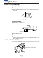
Using the Sony BP-L60/BP-L90 lithium-ion Battery Pack
1
2
Attach the supplied battery mounting terminals.
Attach the lithium-ion battery holder.
A As shown in the figure, remove the battery clamp, and attach the holder using the mounting screws.
B Tighten the power supply contact screws.
C Put the battery clamp back into place.
Battery clamp
|Notes{
ÁThe unit’s power must be set to OFF before the plug is inserted or removed.
ÁTake care when attaching the battery case/battery holder that the wires are not pinched.
– 28 (E) –
CONTENTS
Power Supply
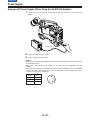
Using an AC Power Supply (When Using the AJ-B75 AC Adaptor)
1
Connect the unit’s EXT DC IN socket with the DC OUT connector of the AJ-B75 AC
adaptor.
DC IN Connector
2
3
Set the AC adaptor’s power to ON.
Set the unit’s power switch to ON.
|Notes{
ÁWhen using an external power supply other than the AJ-B75 AC adaptor, check the pin signal of
the EXT DC IN socket.
ÁWhen both a battery pack and AC adaptor are connected, power is supplied from the AC
adaptor.
ÁWhen using an AC adaptor, the AC adaptor’s power must be set to ON before the unit’s POWER
switch is set to ON. If this sequence is reversed, the AC adaptor’s output voltage will rise slowly
and may cause the unit to malfunction.
Signal
——
4
o12 V
2
GND
1
1
2, 3
3
4
Pin No.
– 29 (E) –
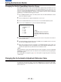
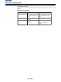
CONTENTS
Power Supply
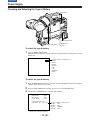
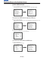
Checking and Selecting the Type of Battery
HOLD button
MENU/ITEM switch
MODE CHECK button
DOWN button
UP button
To check the type of battery
1
Press the MODE CHECK button.
While this button is held down, the type of battery is displayed in the remaining battery charge
display area.
The type of battery is displayed here.
NiCd12
NiCd13
NiCd14
IDX L-40
L-60
L-90
ANTON-D
IDX-D
Display seen inside the viewfinder
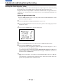
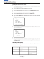
To select the type of battery
1
2
3
When the MENU SET/OFF switch is set to SET while the HOLD button is pressed, the battery
selection menu appears on the screen.
Press the SHIFT/ITEM button, and move the arrow (cursor) to BATTERY SEL.
Press the UP or DOWN button to select the type of battery.
¢| M A S T E R G A I N {
: 0dB
L OW G A I N
: 9dB
M I D GA I N
: 18dB
H I GH GA I N
| BA T T ERY SE L ECT {
BA T T ERY SE L : N i C d 1 2
Display seen inside the viewfinder
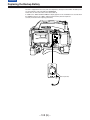
– 30 (E) –
The type of battery is displayed here.
NiCd12
L-60
NiCd13
L-90
NiCd14
ANTON-D
IDX L-40 IDX-D
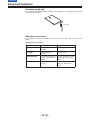
CONTENTS
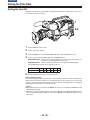
Mounting the Lens
1
Raise the lens clamping lever and remove the mount cap.
Lens Clamping Lever
Mount Cap
2
Align the indentation at the top center of the lens mount with the center mark of the lens and
mount the lens.
Mark
3
Lower the lens clamping lever and clamp the lens.
4
Press the cable into the cable clamp and connect it to the LENS connector.
LENS Connector
ÁSee the Handling Instructions provided with the lens for lens handling.
|Note{
The lens and camera adjustments listed below may be necessary depending on the lens to be
mounted.
1. Lens flange back adjustment
2. Lens auto iris adjustment
3. Lens white shading adjustment (with this unit)
– 31 (E) –
CONTENTS
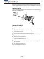
Adjusting the Lens Flange
When images are not clearly focused at both the telephoto and wide-angle positions during zoom
operations, adjust the flange back (the distance from the lens mounting surface to the image
formation surface).
Once adjusted, the flange back does not need to be readjusted as long as the lens is not changed.
Adjustment method
Check the position of each part of the lens which must be operated in order to adjust the flange
back with the lens Handling Instructions.
Approx. 3 m
Adjusting the Flange Back
1
2
3
4
5
6
7
8
9
Set the lens iris to manual.
Open the iris. Position the flange back adjustment chart about 3 m from the lens and illuminate it so that an appropriate image output level is obtained.
Use the CC/ND filters or the shutter if the video level is too high.
Loosen the Ff ring clamping screw.
Set the zoom ring to the telephoto position manually or by electric drive.
Shoot the flange back adjustment chart and turn the distance ring to bring the chart into focus.
Set the zoom ring to the wide-angle position.
Turn the Ff ring to bring the chart into focus.
At this time, take care not to move the distance ring.
Repeat this operation four to seven times until the lens is in focus at both the telephoto and
wide-angle positions.
Firmly tighten the Ff ring clamping screw.
ÁRefer to the Operating Instructions of the lens.
– 32 (E) –
CONTENTS
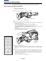
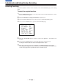
Adjusting the White Shading
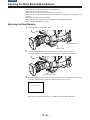
Follow the procedure outlined below when the white shading needs to be re-adjusted.
White shading adjustment procedure
1
2
Mount a lens to the camera.
Be sure to also connect the lens cable.
Set the electronic shutter to OFF and the gain to L (0 dB).
GAIN: L (0 dB)
SHUTTER: OFF
3
4
If the lens has an extender, remove the extender.
Set the MENU SET/OFF switch from OFF to SET while holding down the SHIFT/ITEM and
UP buttons to open the menu.
Press the PAGE button until the MAIN menu screen 2 of 4 appears.
Press the SHIFT/ITEM button to move the cursor to the VF DISPLAY position.
Press the UP or DOWN button to open the VF DISPLAY page.
Set ZEBRA1 DETECT to 70%, ZEBRA2 DETECT to 85% and ZEBRA2 to SPOT. (Initial
setting mode)
Return the MENU SET/OFF switch from SET to OFF to close the menu.
Set the viewfinder’s ZEBRA switch to ON.
|Note{
Adjusting the white
shading incorrectly will
seriously detract from
the camera’s picture
quality. Before starting
the re-adjustment procedure, carefully read
the description of the
white shading adjustment steps contained in
the instruction manual.
If any points are unclear, consult with the
dealer from whom the
unit was purchased for
further
clarification.
Also, make sure to allow
sufficient
time
when performing the
white shading re-adjustment procedure.
MENU
PAGE
SHIFT/ITEM
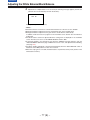
5
6
Shoot an evenly white paper.
Flickering occurs easily when fluorescent or mercury lamps, etc. are used for lighting.
Therefore, use a light source which does no produce flickering such as sunlight or halogen
lamps, etc.
Set the lens iris to manual and adjust the iris so that the ZEBRA pattern covers the entire
screen. If the light strikes the subject in an uneven manner, the ZEBRA pattern will not cover
a part of the screen. Therefore, adjust the position of the light source, etc. as necessary.
Check that the lens iris is between F4 to F11. If the lens iris is not within this range, adjust
the position of the light source, etc.
(Be sure to set the electronic shutter to OFF.)
– 33 (E) –
CONTENTS
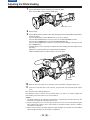
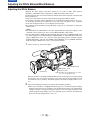
Adjusting the White Shading
7
Set the WHITE BAL selector switch to A or B execute AWB.
Next, execute ABB and then execute AWB again.
WHITE BAL: A or B
8
9
Repeat step 6.
Set the MENU switch from OFF to SET while holding down the SHIFT/ITEM and UP buttons
to open the menu.
Press the PAGE button until the MAIN menu screen 4 of 4 appears.
Press the SHIFT/ITEM button to move the cursor to the AUTO SHADING position.
Press the UP or DOWN button to open the AUTO SHADING page.
Press the SHIFT/ITEM button to move the arrow at the far left to WHITE, and then press the
UP or DOWN button.
ACTIVE appears on the viewfinder to indicate that white shading automatic adjustment is
operating.
Adjustment is completed when the ACTIVE display disappears.
Return the MENU switch from SET to OFF to close the menu.
MENU
PAGE
SHIFT/ITEM
10
11
When the lens to be used has an extender, insert an extender and repeat steps 6 to 9.
If the lens used comes with a ratio converter, insert the ratio converter and repeat steps 6
and 7.
This completes white shading adjustment.
The adjustment value is stored in the non-volatile memory, so there is no need to readjust the
white shading even if the power for the unit is turned off.
|Notes{
1. The white shading can be adjusted for general lenses using the above method. However, this
method may not apply for extremely special lenses.
2. Vertical coloring may occur near the open position of the lens iris even after performing the
above adjustments. However, this is characteristic of the optical system of the lens, and does
not indicate a malfunction.
3. When a ratio converter is provided, adjust the white shading in the 4:3 mode since the ambient
amount of light will drop if the 16:9 mode is established.
– 34 (E) –
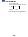
CONTENTS
Adjusting the Viewfinder
(The viewfinder shown in the illustration is the optional AJ-VF10E.)
Adjusting the Position
1
Lift up the viewfinder forward-backward/left/right position clamp lever to release the lock.
Viewfinder
Lever
2
Adjust the position of the viewfinder in the forward-backward and left-right directions.
3
Tighten the viewfinder forward-backward/left-right position clamp lever to the locked position.
– 35 (E) –
CONTENTS
Adjusting the Viewfinder (The viewfinder shown in the illustration is the optional AJ-VF10E.)
Adjusting the Diopter and Screen
Adjusting the diopter
1
2
Set the POWER switch to ON. A picture will appear in the viewfinder.
Turn the diopter adjustment ring to adjust the diopter so that the viewfinder picture can be
clearly seen.
Diopter Adjustment Ring
-3
-2
-1
0
+1
+2
+3
Adjusting the screen
Adjust the condition of the viewfinder screen.
Brightness: Adjust the BRIGHT control
Contrast:
Adjust the CONTRAST control
Contour:
Adjust the PEAKING control
PEAKING Control
CONTRAST Control
BRIGHT Control
1
2
3
Set the POWER switch to ON.
Set the OUTPUT switch to CAM.
Turn the viewfinder BRIGHT and CONTRAST controls to adjust the picture brightness and
contrast. Turning the PEAKING control makes the picture appear softer or sharper. A sharp
picture facilitates focusing the lens.
Adjusting the Eyepiece Position
Turn the eyepiece forward-backward movement ring to adjust the position of the eyepiece in the
forward-backward direction.
Eyepiece Forward-backward Movement Ring
– 36 (E) –
CONTENTS
Adjusting the Viewfinder (The viewfinder shown in the illustration is the optional AJ-VF10E.)
Detaching the Eyepiece
Detaching the eyepiece allows the entire screen to be seen clearly even when shooting with your
eye removed from the viewfinder. This also facilitates the removal of dust which has adhered to
the CRT screen and mirror.
|Note{
Absolutely do not wipe the mirror surface as it has been specially treated. Dust which has adhered
to the mirror should be blown away with a blower, etc.
1
2
Press the lock button.
Turn the lock ring as far as possible in the counter-clockwise direction and line up the alignment marks on the lock ring and viewfinder barrel.
Eyepiece
Alignment Marks
2
Lock Ring
1
Lock Button
3
Detach the eyepiece.
Remounting the eyepiece
1. Line up the alignment marks on the lock ring and the viewfinder barrel, and then insert the
eyepiece.
2. Turn the eyepiece as far as possible in the clockwise direction. The lock button latches with a
clicking sound, and remounting is completed.
– 37 (E) –
CONTENTS
Adjusting the Viewfinder (The viewfinder shown in the illustration is the optional AJ-VF10E.)
Mounting the Viewfinder
1
2
3
Press down the viewfinder.
Tighten the viewfinder stopper screw firmly. If it is difficult to insert the screw, press down the
viewfinder once again.
Connect the plug to the viewfinder connector and secure the viewfinder cable with the clamp.
|Note{
Insert the plug firmly when connecting it to the viewfinder connector.
Stopper Screw
Detaching the Viewfinder
1
2
3
Check that the POWER switch is set to OFF.
Disconnect the plug from the viewfinder cable connector.
|Note{
Use both hands to detach the viewfinder. The viewfinder may not detach smoothly with one
hand, resulting in damage to the viewfinder.
Loosen the viewfinder stopper screw and detach the viewfinder by pulling it straight up.
Pull straight up.
Stopper Screw
Hook your fingers here.
– 38 (E) –
CONTENTS
Audio Input Preparations (The viewfinder shown in the illustration is the optional AJ-VF10E.)
Using the Microphone Mounted to the Main Unit
Using the AJ-MC700P microphone kit (option) or the AJ-MH700P microphone holder (option) allows a microphone to be mounted to the main unit.
ÁSee the Handling Instructions for the microphone holder.
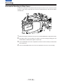
Using the AJ-MC700P Microphone Kit (Option) Microphone Mounted to the
Main Unit
1
Mount the microphone holder.
Viewfinder
Microphone Holder
2
Mount the microphone.
3
Connect the microphone connecting cable to the unit’s MIC IN jack.
MIC IN Connector
– 39 (E) –
CONTENTS
Audio Input Preparations
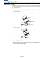
Mounting the AJ-MH700P Microphone Holder (Option)
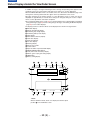
1
Remove the microphone holder mounting screws.
2
Mount the AJ-MH700P microphone adaptor (option) to the main unit.
Mount the microphone
adaptor using the
accessory screws.
3
Mount the microphone to the microphone holder and tighten the screws.
4
Connect the microphone connecting cable to the MIC IN jack.
To the MIC IN Connector
5
Set the AUDIO IN switch to FRONT [MIC] in accordance with the audio channel to be recorded.
– 40 (E) –
CONTENTS
Audio Input Preparations
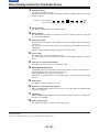
Using the Microphone not Mounted to the Main Unit
ÁFRONT
To the MIC IN Connector
AUDIO IN switch: Set the AUDIO IN switch for
the audio channel you wish to
record to FRONT [MIC].
|Note{
When extending the microphone, use a cable which supports the phantom power supply type of
microphone.
ÁREAR
Up to two external microphones can be connected to
the AUDIO IN CH1/CH2 Connectors.
Phantom power supply can also be supported
by setting the MIC POWER switch to the ON
position.
AUDIO IN Switch: Set the AUDIO IN Switches
of the channels to which
microphones are
connected to REAR [MIC].
– 41 (E) –
CONTENTS
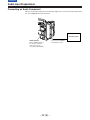
Audio Input Preparations
Connecting an Audio Component
When using an audio component as the line input signal source, connect the audio component to
the unit’s AUDIO IN CH1/CH2 connectors.
Audio Equipment
AUDIO IN Switch:
Set the AUDIO IN Switch of
the channel to which the
audio signal source is
connected to REAR [LINE].
– 42 (E) –
Connect to the AUDIO IN
CH1/CH2 Connectors.
CONTENTS
Mounting the Unit to a Tripod
When mounting the unit to a tripod, use an optional tripod attachment.
1
Mount the tripod attachment (SHAN-TM700) onto the tripod.
Select the attachment hole in consideration of the unit’s and tripod attachment’s centre of
gravity. In addition, check that the diameter of the selected hole matches the diameter of the
universal head’s camera mounting screw.
Tripod Attachment
2
Mount the camera to the tripod attachment.
Slide the unit forward along the grooves until a clicking sound is heard.
When detaching the tripod attachment
Hold down the red lever and move the black lever in the direction of the arrow.
Red Lever
Black Lever
|Note{
When the tripod attachment pin does not return to its original position after the camera has been
detached, hold down the red lever and move the black lever in the direction of the arrow again to
return the pin to its original position.
Care should be taken as the camera cannot be mounted if the pin remains in the centre.
– 43 (E) –
CONTENTS
Mounting the Shoulder Belt
Shoulder Belt
Press to open the hook.
To remove the shoulder belt, open the hooks and then remove the belt.
Press
|Note{
When mounting and removing the shoulder belt, press on the top of the hooks to check that the
belt is securely mounted.
– 44 (E) –
CONTENTS
Adjusting the Shoulder Pad Position
The shoulder pad can be slid up to 10 mm in the forward-backward direction from the centre
position (the position when shipped from the factory). Adjust the shoulder pad position to facilitate
operation of the unit.
1
2
3
Loosen the two screws.
Slide the pad in the forward-backward direction to select an appropriate position.
Tighten the screws to clamp the pad.
Screws
Shoulder Pad
Bottom
– 45 (E) –
CONTENTS
Attaching the Rain Cover
Attach the rain cover as shown in the figure below.
Tighten the Cord.
Secure the surface fastener.
Secure the surface fastener.
When mounting the unit to the tripod
attachment, mount the unit using this hole.
– 46 (E) –
CONTENTS
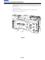
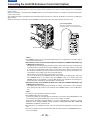
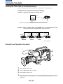
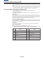
Connecting the AJ-EC3E Extension Control Unit (Option)
Connecting the AJ-EC3E extension control unit (option) allows a portion of the camera section functions to be operated by
remote control.
When the AJ-EC3E is connected and the POWER switches of the unit and AJ-EC3E are set to ON, the unit automatically enters
remote control mode.
The handling instructions included with the AJ-EC3E describe operations for when the AJ-EC3E is connected to an AQ series
digital camera.
When the AJ-EC3E is connected to the AJ-D910WB, some functions differ, and some features cannot be used.
6 pin Cable (VJA1056)
This parts is available as service parts.
For further details, consult with your dealer.
ECU AJECU
6
5
∫
1
R
B
ECU Connector
AJ-EC3E
|Notes{
ÁThe POWER switches of the unit and AJ-EC3E must be set to OFF before the 6-pin cable is
connected or disconnected.
ÁWhen OFF has been set for ECU DATA SAVE on the SUB menu CAMERA SW MODE page
of MAIN menu screen 2 of 4
All adjustments and settings made using the switches and controls on the menu setting section
of the AJ-EC3E are erased when the unit’s POWER switch is set to OFF. Neither is it possible
to save any of the adjustments and settings—except for the menu settings—performed using
the AJ-EC3E’s switches and controls on the setup card. However, when the AJ-EC3E is connected again, these settings return to the AJ-EC3E settings.
(Menu contents set with the menu setting section are saved.)
For use in this mode, set the POWER switch on the AJ-EC3E to the OFF position before the
unit’s POWER switch is set to OFF. If the unit’s POWER switch is set to OFF before the
POWER switch on the AJ-EC3E is set to the OFF position, the adjustments and settings performed when the AJ-EC3E was operated will be saved instead.
ÁWhen ON has been set for ECU DATA SAVE on the SUB menu CAMERA SW MODE page
of MAIN menu screen 2 of 4
The adjustments and settings performed using the switches and controls on the AJ-EC3E’s
menu setting area will not be lost even when the unit’s POWER switch is set to the OFF position.
|Note{
The functions of the AJ-EC3E are limited as follows.
ÁThe STORE switch does not function.
(If the menu settings are changed while the AJ-EC3E is connected to the AJ-D910WB, the new
menu settings are saved automatically as soon as the changes are made.)
Note that the AJ-EC3E gain switch displays p3, 0 and 9 correspond to L, M and H, and the
OUTPUT switch settings CAMERA, TEST and BAR to CAM/AUTO KNEE ON, CAM/AUTO
KNEE OFF and BAR for each main unit.
ÁThe Synchro scan and Super V modes cannot be used while the AJ-EC3E is connected to the
unit.
ÁThe lens iris (IRIS) control of the AJ-EC3E is valid only when the lens iris AUTO/MANUAL selector is set to AUTO.
– 47 (E) –
CONTENTS
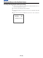
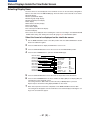
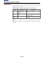
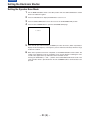
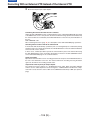
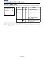
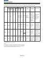
Displaying Menus on the Viewfinder Screen
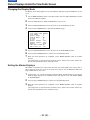
Displaying the Setting Menu Inside the Viewfinder
The setting menus are displayed on the viewfinder screen when the MENU SET/OFF switch is set
to the SET position.
There are two types of setting menus, MAIN menus and SUB menus.
Setting menus are displayed in 1-page increments.
All the pages contained in the setting menus and how each page is configured are shown in the
table below.
The menu configuration can be changed to suit a particular objective.
Setting Menu Configuration
MAIN MENU
MAIN MENU 1/4
(See page 109)
MAIN MENU 2/4
(See page 110)
MAIN MENU 3/4
(See page 111)
MAIN MENU 4/4
(See page 112)
REMOTE
(See page 148)
SUB MENU
ROP (113)
MATRIX (114)
LOW SETTING (115)
MID SETTING (116)
HIGH SETTING (117)
ADDITIONAL DTL (118)
SKIN TONE DTL (119)
KNEE/LEVEL (120)
FLARE/GAMMA (121)
CAMERA SETTING (121)
VF DISPLAY (122)
VF INDICATOR (124)
CAMERA ID (125)
SHUTTER SPEED (125)
SYNCHRO SCAN (126)
!LED (126)
CAMERA SW MODE (127)
SUPER GAIN (128)
VTR FUNCTION (129)
BATT/TAPE ALARM (131)
CARD READ/WRITE (132)
CARD R/W SELECT (133)
REC (ASPECT)/PB/RET (134)
MIC/AUDIO (135)
GENLOCK/IRIS (137)
VIDEO OUT (138)
TIME/DATE (138)
LENS SEL/ADJ (138)
USER MENU SEL 1/3 (139)
USER MENU SEL 2/3 (140)
USER MENU SEL 3/3 (141)
AUTO SHADING (142)
EVALUATION (142)
INITIALIZE (147)
DIAGNOSTIC (147)
VF IND. (REMOTE) (148)
!LED (REMOTE) (149)
TALLY/RET (149)
The figures in parentheses are reference pages.
– 48 (E) –
CONTENTS
Displaying Menus on the Viewfinder Screen
Checking and selecting the master gain setting
1
2
3
4
The menu shown in the figure below is displayed when the MENU SET ON/OFF switch is set
to SET while the HOLD button is held down.
The current low, mid and high gain settings are displayed.
Press the SHIFT/ITEM button, and move the arrow (cursor) to the LOW, MID or HIGH GAIN
menu iten.
Set the gain by pressing the UP or DOWN button. Any value from p3 dB to o30 dB can be
set.
¢| M A S T E R G A I N {
: 0dB
L OW G A I N
: 9dB
M I D GA I N
: 18dB
H I GH GA I N
| BA T T ERY SE L ECT {
BA T T ERY SE L : N i C d 1 2
– 49 (E) –
CONTENTS
Displaying Menus on the Viewfinder Screen
Checking the DIAGNOSTIC Screen Setting
1
2
3
4
Set the MENU SET ON/OFF switch to SET while the HOLD button is held down.
Press the PAGE button.
The menu screen shown in the figure below appears, and it is now possible to check the
DIAGNOSTIC screen settings.
To close the menu screen, return the MENU SET ON/OFF switch to OFF.
O D I A GNO S T I C N
: 0 0 0 0 0 t1 0 h
O P E R A T I ON
D R UM R U N N I NG : 0 0 0 0 0 t 1 0 h
: 0 0 0 0 0 t1 0
T H R E A D I NG
V T R S Y S CON
C AM S Y S CON
D A T A ROM
DV
Ve
Ve
Ve
Ve
r O E t . ttN
r Ot . tNt . t
r Ot . tN
N
r Ot . tt
tt . tt . tt
– 50 (E) –
CONTENTS
Displaying Menus on the Viewfinder Screen
Changing the setting menu configuration
The setting menu can be configured by selecting only the pages necessary for the application.
Pages are selected using the MENU SELECT page of the engineer menu mode.
When using the engineer menu, switch the unit to engineer mode as described below.
The unit is switched to user mode by setting the MENU SET/OFF switch to “SET”.
The unit is switched to engineer mode by holding down the SHIFT/ITEM and UP buttons simultaneously and setting the MENU SET/OFF switch to SET.
The user and engineer modes differ as follows.
User mode:
Only the selected pages the setting menu can be used. The data set on each
page is written to the non-volatile memory, allowing it to be stored for extended periods of time.
Engineer mode: All pages contained in the setting menu can be used. In addition, the data set
at each page is written to the non-volatile memory, allowing it to be stored for
extended periods of time.
If, upon completion of the adjustments and settings in the engineer mode, the menu is set to be
configured only with the frequently used pages, the pages which are often needed can be called
promptly.
(Select the method using the user menu selection procedure described on pages 139 to 141.)
|Note{
The engineer menu will always open if the AJ-EC3E extension control unit (optional accessory) is
connected to the unit and the unit is operated from an external source.
– 51 (E) –
CONTENTS
Displaying Menus on the Viewfinder Screen
Transferring to the MAIN menus and SUB menus
UP/
DOWN
button
MAIN MENU 1/4
SUB menu
SUB MENU
PAGE
button
PAGE button
ÁPress the SHIFT/
ITEM button to
select
the items.
ÁPress the UP and
DOWN buttons to
select the settings.
MAIN MENU 2/4
PAGE button
MAIN MENU 3/4
PAGE button
MAIN MENU 4/4
PAGE button
ÁTo select a page in a SUB menu, first move to the MAIN menu and then select the desired SUB
menu.
ÁChanges are made to the settings on the SUB menus.
– 52 (E) –
CONTENTS
Displaying Menus on the Viewfinder Screen
Basic Setting Menu Operations
The setting menu is operated using the MENU SET/OFF switch and the SHIFT/ITEM, UP, DOWN
and PAGE buttons.
PAGE Button
SHIFT/ITEM Switch
SHIFT/
ITEM
PAGE
AUDIO IN
TCG
F-RUN
SET
R-RUN
UP
MIC
MIC
LINE
FRONT
REAR
UP Button
CH 1
SET
DOWN Button
CUE
MENU
DOWN
OFF
CH 2
REAR MIC POWER
CH 1
MIX
CH 2
ON
OFF
MENU SET/OFF Switch
To display a SUB menu directly (user mode)
1
Set the MENU SET/OFF switch to the SET position.
The status displays at the top and bottom of the viewfinder screen are cleared, and the page
on which the previous setting menu operation was completed now appears on the screen.
When a menu is used for the first time, the page with the lowest number among the selected
pages appears on the screen.
¢| RO P {
MA S T E R P E D
MA S T E R D T L
MA S T E R G AMMA
R GA I N
B GA I N
R PEDES T A L
G PEDES T A L
B PEDES T A L
:
:
:
:
:
:
:
:
µ0 0 2
µ0 0
0 . 45
µ0 0 0
µ0 0 0
µ0 0 0
µ0 0 0
µ0 0 0
To display a MAIN menu directly (engineer mode)
1
Set the MENU SET/OFF switch to the SET position while the SHIFT/ITEM button and UP
button are held down together.
MAIN menu screen 1 of 4 now appears.
¢ E E E E MA I N ME N U 1 / 4 E E E E
RO P
MA T R I X
L OW S E T T I NG
M I D S E T T I NG
H I GH S E T T I NG
A D D I T I ON A L D T L
S K I N T ON E D T L
KNEE / L EVE L
F L A R E / G AMMA
C AME R A S E T T I NG
The pages can also be selected using the UP and DOWN buttons in combination with the PAGE
button as indicated below.
ÁPAGEµUP:
When the UP button is pressed while the PAGE button is held down, operation advances to the next menu and the menu next to it and so on for as long
as the button is held down.
ÁPAGEµDOWN: When the DOWN button is pressed while the PAGE button is held down, operation is returned to the previous menu and the menu before it and so on for as
long as the button is held down.
– 53 (E) –
CONTENTS
Displaying Menus on the Viewfinder Screen
To select a MAIN menu page
1
Press the PAGE button to select a particular MAIN menu.
Each time the button is pressed, the MAIN menu screen is advanced by one page
(1>2>3>4>1>, etc.).
¢ E E E E MA I N ME N U 1 / 4 E E E E
RO P
MA T R I X
L OW S E T T I NG
M I D S E T T I NG
H I GH S E T T I NG
A D D I T I ON A L D T L
S K I N T ON E D T L
KNEE / L EVE L
F L A R E / G AMMA
C AME R A S E T T I NG
PAGE button
¢ E E E E MA I N ME N U 2 / 4 E E E E
VF D I SPLAY
V F I N D I C A T OR
C AME R A I D
SHU T T ER S P E ED
S Y N C H RO S C A N
! L ED
C AME R A SW MOD E
SUP ER GA I N
V T R F U N C T I ON
B A T T / T A P E A L A RM
To transfer from a MAIN menu to a particular SUB menu
1
Press the SHIFT/ITEM button.
When this button is pressed, the cursor (arrow) indicating the selected item moves to the
SUB menu.
¢ E E E E MA I N ME N U 1 / 4 E E E E
RO P
MA T R I X
L OW S E T T I NG
M I D S E T T I NG
H I GH S E T T I NG
A D D I T I ON A L D T L
S K I N T ON E D T L
KNEE / L EVE L
F L A R E / G AMMA
C AME R A S E T T I NG
2
SHIFT/ITEM button
E E E E MA I N ME N U 1 / 4 E E E E
¢ RO P
MA T R I X
L OW S E T T I NG
M I D S E T T I NG
H I GH S E T T I NG
A D D I T I ON A L D T L
S K I N T ON E D T L
KNEE / L EVE L
F L A R E / G AMMA
C AME R A S E T T I NG
Press the UP or DOWN button.
Operation is now switched to the selected SUB menu.
¢| RO P {
MA S T E R P E D
MA S T E R D T L
MA S T E R G AMMA
R GA I N
B GA I N
R PEDES T A L
G PEDES T A L
B PEDES T A L
:
:
:
:
:
:
:
:
µ0 0 2
µ0 0
0 . 45
µ0 0 0
µ0 0 0
µ0 0 0
µ0 0 0
µ0 0 0
To transfer from a SUB menu to the MAIN menu
1
Press the PAGE button.
Operation moves to the MAIN menu.
¢| RO P {
MA S T E R P E D
MA S T E R D T L
MA S T E R G AMMA
R GA I N
B GA I N
R PEDES T A L
G PEDES T A L
B PEDES T A L
:
:
:
:
:
:
:
:
µ0 0 2
µ0 0
0 . 45
µ0 0 0
µ0 0 0
µ0 0 0
µ0 0 0
µ0 0 0
PAGE button
– 54 (E) –
¢ E E E E MA I N ME N U 1 / 4 E E E E
RO P
MA T R I X
L OW S E T T I NG
M I D S E T T I NG
H I GH S E T T I NG
A D D I T I ON A L D T L
S K I N T ON E D T L
KNEE / L EVE L
F L A R E / G AMMA
C AME R A S E T T I NG
CONTENTS
Displaying Menus on the Viewfinder Screen
Operations on SUB menus
Selecting the desired item
1
Press the SHIFT/ITEM button.
Each time this button is pressed, the cursor (arrow) which indicates the selected item moves
to the next item.
¢| RO P {
Cursor
Movement order
†MA S T E R
PED
MA S T E R D T L
MA S T E R G AMMA
R GA I N
B GA I N
R PEDES T A L
G PEDES T A L
B PEDES T A L
:
:
:
:
:
:
:
:
µ0 0 2
µ0 0
0 . 45
µ0 0 0
µ0 0 0
µ0 0 0
µ0 0 0
µ0 0 0
The item can also be selected using the UP and DOWN buttons as follows.
Changing the settings
Press the UP button to increase the setting.
ÁThe setting is incremented by 1 level each time
the UP button is pressed.
Press the DOWN button to decrease the setting.
ÁThe setting is decremented by 1 level each time
the DOWN button is pressed.
SHIFT/
ITEM
PAGE
AUDIO IN
TCG
F-RUN
SET
R-RUN
UP
MIC
MIC
LINE
FRONT
REAR
CH 1
CUE
MENU
DOWN
SET
OFF
CH 2
REAR MIC POWER
CH 1
MIX
CH 2
ON
OFF
Changing the ON/OFF selection
The setting switches to ON or OFF each time the UP (or DOWN) button is pressed.
Returning to the default settings
Align the arrow with READ FACTORY DATA on the “INITIALIZE” SUB menu page of the MAIN
menu screen 4 of 4.
When the UP (or DOWN) button is now pressed, the initial (factory) settings will be restored.
However, care should be taken as the camera ID cannot be returned to the default settings.
Quitting the menu
Set the MENU SET/OFF switch to OFF.
ÁThe setting menu disappears from the viewfinder screen and the displays indicating the unit’s
current status appear at the top and bottom of the viewfinder screen.
– 55 (E) –
CONTENTS
Lamp Displays Inside the Viewfinder
The viewfinder displays are as follows.
1
5
REC
50
!
BATT
3
2
VTR SAVE
4
1. REC (recording) lamp
This lamp lights (red) during recording, and flashes when warnings are issued.
ÁSee “Warning System” (page 150, 151) for a detailed description.
2. BATT (battery) lamp
When the battery voltage has dropped, this lamp begins flashing several minutes before the
unit can no longer be operated, and lights when the unit can no longer be operated.
To prevent operation from being interrupted, exchange the battery quickly before the battery
runs out.
ÁSee “Warning System” (page 151) for a detailed description.
3. ! (irregular operation status warning) lamp
This lamp lights when the unit enters irregular operation status for any of the items set to ON at
the ! LED page of the setting menu. Applicable items are as follows.
Setting item
Setting contents
Gain (0 dB)
The gain is set to a value other
than 0 dB.
Gain (p3 dB)
The gain is set to a value other
than p3 dB.
SHUTTER switch
The switch is set to ON.
WHITE PRESET switch
The switch is set to PRESET.
Lens extender
The lens extender is being used.
Filter control
The control is set to a value
other than 1B.
SUPER V switch
The switch is set to ON.
25M/50M
Lamp lights when the 25 or
50 Mbps recording format is set.
ÁSee “Setting the ! Lamp Display” (next page) for selecting ! lamp display items.
4. VTR SAVE (VTR power saving) lamp
This lamp lights when the VTR SAVE/STBY switch is set to SAVE. It is not lit during recording.
5. 50 (50Mbps recording/playback) lamp
This lamp lights when the mode for recording at 50 Mbps is selected and when a tape is played
back at 50 Mbps.
|Note{
The SAVE status is automatically established and the lamp lights regardless of the VTR SAVE/
STBY switch position at the time set by the pause timer (pause time) when the unit is in the
recording pause mode or when 2 minutes have elapsed since the unit was placed in the playback
pause mode.
– 56 (E) –
CONTENTS
Lamp Displays Inside the Viewfinder
Setting the ! Lamp display
The items subject to the ! lamp display are selected on the “! LED” SUB menu page on the MAIN
menu screen 2 of 4. (Under the factory setting, the “! LED” page is not displayed.) To perform
operations on the “! LED” page, either switch the unit to the engineer mode or select the “! LED”
page on the USER MENU SEL page 2 of 3 on the MAIN menu screen 4 of 4.
ÁFor details on selecting the engineer mode and display page, refer to Setting Menu Configuration (page 52).
1
2
3
4
Set the MENU SET/OFF switch to the SET position while the SHIFT/ITEM button and UP
button are held down together.
Press the PAGE button to display the MAIN menu screen 2 of 4.
Repeatedly press the SHIFT/ITEM button to move the cursor to the “! LED” position.
Press the UP or DOWN button to open the ! LED page.
¢|
! L ED {
GA I N ( 0 d B )
GA I N ( ∂3 d B )
SHU T T ER
WH I T E P R E S E T
E X T ENDER
F I L T ER
SUPER V
2 5M / 5 0M
GAIN (0 dB):
GAIN (¶3 dB):
SHUTTER:
WHITE PRESET:
EXTENDER:
FILTER:
SUPER V:
25M/50M:
5
6
: ON
: OF F
: ON
: OF F
: ON
: OF F
: OF F
: OF F
This selects whether the ! lamp is to light when the gain is set to a value other than
0 dB.
This selects whether the ! lamp is to light when the gain is set to a value other than
p3 dB.
This selects whether the ! lamp is to light when the SHUTTER switch is set to the
ON position.
This selects whether the ! lamp is to light when the white balance memory channel is
set to PRST.
This selects whether the ! lamp is to light when the lens is in the EXTENDER mode.
This selects whether the ! lamp is to light when the filter is set to a position other than
3200K and CLEAR. (1B)
This selects whether the ! lamp is to light when SUPER V is set to ON.
This selects whether the ! lamp is to light when the recording format is set to
25 Mbps or 50 Mbps.
Repeatedly press the SHIFT/ITEM button to move the cursor to the position of the desired
item.
Press the UP or DOWN button at the selected item to select whether the ! lamp is to be set
ON or OFF.
To select ON: Press the UP button.
To select OFF: Press the DOWN button.
To select ON or OFF for another item, repeat steps 5 and 6.
7
When the menu operations are completed, return the MENU SET/OFF switch to the OFF
position.
The setting menu is cleared from the viewfinder screen, and the unit’s current statuses appear at the top and bottom of the viewfinder screen.
– 57 (E) –
CONTENTS
Status Displays Inside the Viewfinder Screen
In addition to images, messages indicating the unit’s settings and operating status appear on the
viewfinder screen. The centre marker and safety zone marker, etc. are also displayed.
When the MENU SET/OFF switch is set to OFF, items set to SET at the VF DISPLAY page of the
setting menu and using related switches appear at the top and bottom of the screen.
Messages informing of the setting contents or of the adjustment course or results can also be
displayed for approximately 3 seconds when settings are changed, during the course of adjustments, or after adjustments have been completed.
ÁSee “Selecting Display Items” (page 61) for selecting display items, “Display Mode and Setting
Change Message” (page 62) for the setting change message, and “Setting the Marker Displays”
(page 63) for the marker displays.
The display positions of all items which can be displayed are shown in the figure below.
e Extender display
f Shutter speed/mode display
g Remaining tape length display
h Remaining battery level display
i Filter display
j White balance memory display
k Gain value display
l Audio level display
m Iris value display
n Warning display
o Safety zone marker
p Centre marker
q Super iris ON or super black ON display
r MARK1/MARK2/TAKE display
s TCG (Time Code Generator) display
t Master gain & super gain setting display
u 50M display
v Battery setting display
1
o
2
EX2 1/250
q
3
S
30-25
s
4
14.6V
50M
NiCd12
t
o
u
v
p
n
1B
A
0dB
-------
T_M1
F5.6
5
6
7
8
9
o
r
o
|Note{
When in SUPER V mode, “SUP. V” is displayed at shutter speed
position f in the Viewfinder screen.
– 58 (E) –
CONTENTS
Status Displays Inside the Viewfinder Screen
1
2
3
Extender display
This is displayed when the lens extender is being used.
Shutter speed/mode display
This displays the shutter speed or shutter mode setting.
OFF (OFF is not displayed.): The shutter is not used.
1/60, 1/120, 1/250, 1/500, 1/1000, 1/2000:
Shutter speeds (seconds) during standard mode.
1/50.6–1/248.0 (SYNCHRO SCAN):
Synchro scan mode is selected.
SUPER V:
High vertical resolution mode is selected.
Remaining tape length display
This indicates the remaining tape length (minutes) for the VTR during recording.
Remaining tape length display
(25 Mbps)
Display
4
Remaining tape
length
Remaining tape length display
(50 Mbps)
Display
Remaining tape
length
F–60
Full to 60 minutes
F–30
Full to 30 minutes
60–55
60 to 55 minutes
30–25
30 to 25 minutes
55–50
55 to 50 minutes
25–20
25 to 20 minutes
50–45
50 to 45 minutes
20–15
20 to 15 minutes
45–40
45 to 40 minutes
15–10
15 to 10 minutes
40–35
40 to 35 minutes
10–5
10 to 5 minutes
35–30
35 to 30 minutes
5–0
5 to 0 minutes
30–25
30 to 25 minutes
25–20
25 to 20 minutes
20–15
20 to 15 minutes
15–10
15 to 10 minutes
10–5
10 to 5 minutes
5–0
5 to 0 minutes
The “5–0” display flashes when there is
less than 2 minutes of tape remaining.
Remaining battery level display
When an Anton Bauer Digital Magnum Series battery is used to supply power to the unit, the
remaining battery level is displayed numerically (%).
|Note{
When a Digital Magnum series battery made by Anton Bauer is used to supply external
power to the unit near the battery end, the remaining battery level display will show the
external voltage, and the unit will be operated by the external power supply.
5
6
7
Filter display
This displays the type of filter selected.
White balance memory display
This displays the selected white balance automatic adjustment memory.
A: The WHITE BAL switch is set to A.
B: The WHITE BAL switch is set to B.
P: The WHITE BAL switch is set to PRST.
Gain value display
This displays the image amplifier gain setting (dB) set by the GAIN switch.
– 59 (E) –
CONTENTS
Status Displays Inside the Viewfinder Screen
8
Audio level display
This displays the audio CH1 level.
During sine wave input, the audio level display corresponds roughly to the VTR level meter
display as follows.
Audio Channel 1 Level Display
VTR Level Meter
9
10
11
12
13
14
15
16
17
18
E
-40 -30 -25 -20 -15 -10 -5 0
Iris value display
This displays the approximate iris setting (F number).
Warning display
This displays the black balance, white balance, auto knee function, super iris, super gain
and other warning displays.
Safety zone marker
This indicates the safety zone to be the 80% or 90% (factory setting) range of the viewfinder
screen area.
The ratio of this area to the total screen area is selected on the VF DISPLAY page of the
setting menu.
ÁRefer to “Setting the Marker Displays” (page 63) for further details.
Centre marker
This indicates the centre of the viewfinder screen.
The marker appears when its display is set to ON on the VF DISPLAY page of the setting
menu.
Super iris (or super black) ON display
This indicates that the super iris (or super black) is ON.
MARK1/MARK2/TAKE display
If the MARK switch is pressed while the Picture Link function is used, M1 or M2 appears to
indicate the significance of the information concerned.
Nothing will appear if this function is not required.
Alternatively, T_ (TAKE) appears when the RET switch of the lens is used as the TAKE
function.
TCG display
This displays the time code generator value.
Master gain & super gain setting display
When the MODE CHECK button is pressed, the current GAIN L/M/H and SUPER GAIN
settings are displayed.
50M display
When the MODE CHECK button is pressed, this display appears when the recording format
has been set to 50 Mbps.
Battery setting display
This indicates the type of the battery currently being used.
1) Iris value display
The iris value is displayed when using a lens with the iris value display function.
– 60 (E) –
CONTENTS
Status Displays Inside the Viewfinder Screen
Selecting Display Items
The items which are to be displayed on the viewfinder screen can be selected by setting ON or
OFF for each item on the VF INDICATOR page. The items which can be selected are as follows.
ÁExtender display
ÁShutter speed/mode display
ÁRemaining tape length display
ÁRemaining battery level display
ÁFilter display
ÁWhite balance memory display
ÁGain value display
ÁLevel meter display
ÁIris value/super iris ON status display
ÁCamera ID display
ÁThe camera ID is displayed when recording the colour bar according to the OUTPUT/AUTO
KNEE switch setting. See “Setting the Camera ID” (page 64) for a detailed description.
Select the items to be displayed on the viewfinder screen.
1
2
3
4
Set the MENU SET/OFF switch to the SET position while the SHIFT/ITEM button and UP
button are held down together.
Press the PAGE button to display the MAIN menu screen 2 of 4.
Press the SHIFT/ITEM button to move the cursor to the “VF INDICATOR” position.
Press the UP or DOWN button to open the VF INDICATOR page.
Extender display
Shutter speed/mode display
Remaining tape length display
Remaining battery level display
Filter display
White balance memory display
Gain value display
Level meter display
Iris value/super iris ON status display
Camera ID display
DATE/TIME display
5
6
7
>O V F I N D I C A T OR N
: ON
E X T ENDER
: ON
SHU T T ER
: ON
TAPE
: ON
BA T T ERY
: ON
F I L T ER
: ON
WH I T E
: ON
GA I N
L E V E L ME T E R : C H 1
: Sr I R I S
IRIS
: ON
C AME R A I D
: OF F
D A T E / T I ME
Press the SHIFT/ITEM button to move the cursor to the position of the disired item.
Press the UP and DOWN buttons to choose whether to display (ON) or not display (OFF) the
selected item on the viewfinder screen.
The setting switches to ON or OFF each time the UP (or DOWN) button is pressed.
Repeat steps 5 and 6 when setting display ON/OFF for other items.
When menu operations have been completed, set the MENU SET/OFF switch to OFF.
The setting menu disappears from the viewfinder screen and the displays indicating the settings of the selected items appear.
– 61 (E) –
CONTENTS
Status Displays Inside the Viewfinder Screen
Display Mode and Setting Change Message
Messages informing of the contents of changed settings and adjustment results can be limited to
part of the displayed items or not displayed for all items.
The conditions under which messages are displayed and the corresponding display modes are
shown in the table below.
Setting change/adjustment results messages and display modes
Conditions under which
messages are displayed
Display mode
setting
Message
1
2
3
When the filter selection is
changed.
Filter: n (nr1, 2, 3, 4)
q
q
¿
When the gain setting is
changed.
GAIN: n dB (nrp3, 0, 3, 6, 9, 12, 15, 18,
GAIN: 21, 24, 30, 36, 43, 46)
q
q
¿
When the WHITE BAL switch
setting is changed.
WHITE: n (nrACH, BCH, PRESET)
q
q
¿
When the OUTPUT/AUTO
KNEE switch is set to AUTO
KNEE or OFFF)
AUTO KNEE: ON (or OFF)
q
¿
¿
When the shutter speed/
mode setting is changed.
SS: 1/60 (or 1/120, 1/250, 1/500,
SS: 1/1000,1/2000, S. SCAN, SUPER V)
q
¿
¿
When the white balance is
adjusted (AWB)
Ex.) AWB: OK
ÁSee “Adjusting the White Balance”
(page 71) for a detailed description.
q
¿
¿
When the black balance is
adjusted (ABB)
Ex.) ABB: OK
ÁSee “Adjusting the Black Balance”
(page 76) for a detailed description.
q
¿
¿
¿: Message displayed
q: Message not displayed
F) The message is displayed for approximately 3 seconds immediately after the power for the unit is
turned on.
|Note{
Whether a message is displayed or not also depends on the status of other menu settings.
For instance, even if the filter selection is set to “1B”, the filter message will appear if FILTER is set
to ON on the VF INDICATOR page.
– 62 (E) –
CONTENTS
Status Displays Inside the Viewfinder Screen
Changing the Display Mode
The display mode setting appears on the “VF DISPLAY” SUB menu page of MAIN menu screen
2 of 4.
1
2
3
4
Set the MENU SET/OFF switch to the SET position while the SHIFT/ITEM button and UP
button are held down together.
Press the PAGE button to display the MAIN menu screen 2 of 4.
Press the SHIFT/ITEM button to move the cursor to the “VF DISPLAY” position.
Press the UP or DOWN button to open the VF DISPLAY page.
¢| V F D I S P L A Y {
D I S P CON D I T I ON : NORMA L
:3
D I S P MOD E
:3
S A F E T Y Z ON E
: ON
C E N T R E MA R K
:Y
V F OU T
:2
VF DT L
Z E BRA 1 DE T EC T : 0 7 0%
Z E BRA 2 DE T EC T : 0 8 5%
: S POT
Z EBRA 2
5 0 M I N D I C A T I ON : ON
L OW L I GH T L V L : 4 5 %
5
6
7
Press the SHIFT/ITEM button to move the cursor to the “DISP MODE” position.
Press the UP (or DOWN) button to switch to the desired display mode.
When the menu operations are completed, set the MENU SET/OFF switch to the OFF
position.
The setting menu is cleared from the viewfinder screen, and the unit’s current statuses appear at the top and bottom of the viewfinder screen.
Setting the Marker Displays
ON or OFF is selected for the centre mark and safety zone mark display and a ratio of 80% or
90% of the total screen area is set for the safety zone range on the “VF DISPLAY” SUB menu
page of MAIN menu screen 2 of 4.
1
2
3
Perform steps 1 to 4 under “Changing the Display Mode” described above so that the VF
DISPLAY page appears on the viewfinder screen, and align the cursor with SAFETY ZONE
or CENTRE MARK.
Press the UP (or DOWN) button to switch to the desired display mode.
When the menu operations are completed, set the MENU SET/OFF switch to the OFF
position.
The setting menu is cleared from the viewfinder screen, and the unit’s current statuses appear at the top and bottom of the viewfinder screen.
– 63 (E) –
CONTENTS
Status Displays Inside the Viewfinder Screen
Setting the Camera ID
The camera ID can be set at the CAMERA ID page of the setting menu.
A camera ID of up to ten characters including English letters, symbols and spaces can be used.
The camera ID is recorded when the OUTPUT/AUTO KNEE switch is set to BARS and the colour
bar signal is being recorded. It is also displayed on the viewfinder screen.
|Note{
When the setting menu is displayed, the camera ID is not displayed even if the colour bar signal is
output.
1
2
3
4
Set the MENU SET/OFF switch to the SET position while the SHIFT/ITEM button and UP
button are held down together.
Press the PAGE button to display the MAIN menu screen 2 of 4.
Press the SHIFT/ITEM button to move the cursor to the “CAMERA ID” position.
Press the UP or DOWN button to open the CAMERA ID page.
¢| C AME R A
ID {
I D : EEEEEEEEEE
: The cursor is moved to the right (max. 10 spaces) by the
SHIFT/ITEM button.
: Alphanumerics, symbols and spaces are selected by the
UP and DOWN buttons.
5
6
7
Keep pressing the UP (or DOWN) button until the character to be set appears.
Each time the UP button is pressed, the character display changes in the following order:
space (Å)¢english letters (A to Z)¢numbers (0 to 9)¢symbols (space, {, |, ), (, ’, ‘, ,, --,
_ , x, /, !). Pressing the DOWN button changes the character display in the reverse order.
Press the SHIFT/ITEM button to move the cursor to the next position, and return to step 5 to
set the characters.
When the menu operations are completed, set the MENU SET/OFF switch to the OFF
position.
The setting menu is cleared from the viewfinder screen, and the unit’s current statuses appear at the top and bottom of the viewfinder screen.
<Note>
When CAMERA ID on the VF INDICATOR page has been set to ON, the above camera ID setting
will be recorded along with the colour bars.
– 64 (E) –
CONTENTS
Displays
Remaining Battery Level and Audio Level Displays
Remaining tape length
When the amount remaining
on the tape is more than
30 minutes long, all seven segments up to the “F” position appear lit.
When it is less than 30 minutes
long, one segment will go off
for every 5-minute reduction in
the length.
Remaining battery level
When the digital display (%
display) battery is used, the
7 segments light up all the way
to the “F” position if the remaining battery level is more than
70%.
If the remaining battery level is
under 70%, one of the segments goes off for each further
10% reduction in the remaining
level.
SLAVE TCG HOLD WIDE
EMPHASIS
0
h
min
s
10
frm
E
TAPE
F
E
BATT
F
Audio CH level meter
20
30
40
RF SERVO HUMID SLACK
CH1
dB
CH2
VTR Section Operation/Status-Related Displays
SLAVE TCG HOLD WIDE
Lights
SLAVE
TCG
HOLD
WIDE
EMPHASIS
0
h
Error code:
Indicated in the display
window.
min
s
10
frm
E
TAPE
F
E
BATT
F
20
30
40
RF SERVO HUMID SLACK
CH1
Warning display
RF:
Lights when video head clogging occurs.
SERVO: Lights when the servo is out of order.
HUMID: Lights when condensation occurs on the head drum.
SLACK: Lights when tape wind-up trouble occurs.
ÁSee “Warning System” (page 150) for a detailed description.
– 65 (E) –
dB
CH2
CONTENTS
Displays
Time Code-Related Displays
SLAVE TCG HOLD WIDE
EMPHASIS
0
h
min
s
10
frm
E
TAPE
F
E
BATT
F
20
30
40
RF SERVO HUMID SLACK
CH1
dB
CH2
These lamps light to indicate the time code, CTL and real time displays.
SLAVE: This lamp lights when the time code is locked to an external source.
HOLD: This lamp lights when the time code generator is held (when the HOLD button is pressed).
WIDE:
This lamp lights when a tape is recorded or played back with an aspect ratio of 16:9.
Time counter display: This displays the time code, CTL, user bit and real time.
ÁSee below for the relationship between displayed items and switch settings.
Relationship between the TCG and DISPLAY switch setting positions and the time counter
display
The item displayed in the time counter display is determined by the TCG switch and DISPLAY
switch settings.
Time code-related switch settings and display items
TCG switch
position
SET
F-RUN or R-RUN
DISPLAY switch
position
Displayed item
TC or CTL
Time code
UB
User bit
CTL
CTL
TC
Time code
UB
User bit
– 66 (E) –
CONTENTS
Adjusting the Time and Date
Adjustment and setup using the setting menu
1
2
3
4
Set the MENU SET/OFF switch to the SET position while the SHIFT/ITEM button and UP
button are held down together.
Press the PAGE button to display the MAIN menu screen 3 of 4.
Press the SHIFT/ITEM button to move the cursor to the “TIME/DATE” position.
Press the UP or DOWN button to open the TIME/DATE page.
¢| T I ME / D A T E {
YEAR
MON T H
DAY
HOU R
M I NU T E
:
:
:
:
:
99
01
01
00
00
» T I ME / D A T E S E T
5
6
Press the SHIFT/ITEM button to select the item to be changed.
Press the UP (or DOWN) button to change the setting value.
The number is incremented by o1 each time the UP button is pressed and decremented by
p1 each time the DOWN button is pressed.
| T I ME / D A T E {
YEAR
MON T H
DAY
HOU R
¢M I N U T E
:
:
:
:
:
99
01
01
00
00
» T I ME / D A T E S E T
7
When the settings have been completed, press the SHIFT/ITEM button to select TIME/DATE
SET and then press the UP (or DOWN) button. The time starts from when the button is
pressed.
» T I ME / D A T E S E T
8
When menu operations have been completed, set the MENU SET/OFF switch to OFF.
The setting menu disappears from the viewfinder screen and the displays indicating the unit’s
current status appear at the top and bottom of the viewfinder screen.
|Note{
The seconds cannot be set and always start from 0 seconds.
– 67 (E) –
CONTENTS
Adjustments and Setup During Recording
Adjustments and Setup Using the Setting Menu
Adjustments and setup operations during recording are performed at the setting menu.
Setting menu operations are basically performed according to the procedures described on
page 53.
However, these procedures vary slightly according to the item.
Items which can be adjusted or set up at the setting menu are as follows.
Adjustment/setup items at the setting menu
Adjustment/setup item
Page name
Operation reference
Setting the gain selector value
SETTING
(LOW/MID/HIGH)
Setting the Gain Selector
Value, Setting the DTL and
gamma, etc.
Selecting the shutter speed/
mode to be used
SHUTTER SPEED
Setting the Electronic
Shutter
Setting the synchro scan mode
shutter speed
SYNCHRO SCAN
Setting the Electronic
Shutter
Selecting the required VTR
functions
VTR FUNCTION
Selecting Functions
Shading adjustment
AUTO SHADING
Shading Adjustment
Setup card data operations
SET UP CARD
Setup Card Operations
– 68 (E) –
CONTENTS
Adjustments and Setup During Recording
Setting the Gain Selector Value
When shooting in locations without sufficient brightness, bright images can be obtained by raising
the gain. However, care should be taken as raising the gain also increases the noise.
The gain value for the image amplifier is selected by the GAIN switch. The gain values corresponding to the L, M and H positions of the GAIN switch are set at the MASTER GAIN page of the
setting menu.
Setting the gain selector value
1
2
3
4
Set the MENU SET/OFF switch to the SET position while the SHIFT/ITEM button and UP
button are held down together.
Press the PAGE button to display the MAIN menu screen 1 of 4.
Press the SHIFT/ITEM button to move the cursor to the position of the setting page on which
the gain is to be set.
Press the UP or DOWN button to open the setting page.
¢| L OW S E T T I NG {
»MA S T E R G A I N
H . DT L LEVEL
V . DT L LEVEL
D T L COR I NG
H . D T L F REQ .
DARK DT L
L E V E L DE P END .
MA S T E R G AMMA
»B L A C K S T R E T C H
»M A T R I X T A B L E
5
6
: 0dB
: 10
: 10
: 05
: 03
: 00
: 00
: 0 . 45
: OF F
:A
Press the SHIFT/ITEM button to move the cursor to the “MASTER GAIN” position.
Press the UP or DOWN button to set the gain value.
Any gain value can be set regardless of whether it is high or low from among the p3, 0, 3, 6,
9, 12, 15, 18, 21, 24 and 30 dB setting options.
To reset the gain values to their factory settings (LOWr0dB, MIDr9dB, HIGHr18dB), select
READ FACTORY DATA on the “INITIALIZE” SUB menu page on MAIN menu screen 4 of 4,
and press the UP or DOWN button.
7
When the menu operations are completed, set the MENU SET/OFF switch to the OFF position.
The setting menu is cleared from the viewfinder screen, and the unit’s current statuses appear at the top and bottom of the viewfinder screen.
– 69 (E) –
CONTENTS
Adjustments and Setup During Recording
Selecting Functions
The VTR’s operation functions can be selected on the “VTR FUNCTION” page of the setting
menu.
To select the required functions
1
2
3
4
Set the MENU SET/OFF switch to the SET position while the SHIFT/ITEM button and UP
button are held down together.
Press the PAGE button to display the MAIN menu screen 2 of 4.
Press the SHIFT/ITEM button to move the cursor to the “VTR FUNCTION” position.
Press the UP or DOWN button to open the VTR FUNCTION page.
¢| V T R F U N C T I ON {
H UM I D O P E
2 6 P CON T RO L
REC S T ART
U B MOD E
P A U S E T I ME R
BA T T ERY SE L
T CG V F D I S P
T CG S E T HO L D
F I RS T REC TC
5
6
7
: OF F
: OF F
: NORMA L
: USER
: 30
: N i Cd 1 2
: OF F
: OF F
: REGEN
Press the SHIFT/ITEM button to move the cursor to the position of the function to be
changed.
Press the UP (or DOWN) button to change the setting of the selected function.
If settings for other functions are also to be changed, return to step 5.
When menu operations have been completed, set the MENU SET/OFF switch to OFF.
The setting menu disappears from the viewfinder screen and the displays indicating the unit’s
current status appear at the top and bottom of the viewfinder screen.
– 70 (E) –
CONTENTS
Adjusting the White Balance/Black Balance
Adjusting the White Balance
Adjusting the white balance and black balance in the order of AWB (white balance
adjustment)>ABB (black balance adjustment)>AWB will provide a better picture.
The black balance does not normally need to be readjusted even when the power is turned off and
then turned back on.
However, the white balance must be readjusted when the lighting conditions change.
If black balance and white balance adjustments are started when the display mode is set to “2” or
“3”, messages informing of the adjustment course and results will appear on the viewfinder
screen. Set the display mode to “1” to not display these messages.
ÁSee “Display Mode and Setting Change Message” (page 62) for a description of setting the
display mode.
|Notes{
ÁThe white balance and black balance cannot be adjusted while the setting menu appears on the
viewfinder screen. Therefore, be sure to set the MENU SET/OFF switch to OFF.
ÁThe auto black balance (ABB) must be readjusted without fail when the MASTER GAIN value
has been changed on the “LOW SETTING”, “MID SETTING” or “HIGH SETTING” SUB menu
pages of MAIN menu screen 1 of 4, when the super gain setting has been changed using the
SUPER GAIN button, and when the GAMMA setting (ON/OFF) on the “CAMERA SETTING”
SUB menu page of MAIN menu screen 1 or 4 has been switched.
1
Set the switches as shown in the figure.
MENU SET/OFF: OFF
FILTER knob
WHITE BAL: A or B
OUTPUT: CAM
GAIN: Normally, set to 0 dB. When it is too dark,
it is set to the appropriate gain.
When the positions of the GAIN and WHITE BAL switches are changed, a message informing
the operator of the new settings will appear on the setting change message display area of
the viewfinder screen. (However, this display appears only when the display mode is set to
“3”.)
2
Select the FILTER knob setting in accordance with the lighting conditions.
ÁRefer to the description of the ¬ FILTER knob (page 16) in the Shooting and Recording/
Playback Function Section for examples of the FILTER knob settings. If the FILTER knob
setting is changed, a message informing the operator of the new setting will appear on the
setting change message display area of the viewfinder screen. (However, this display appears only when the display mode is set to “3”.)
– 71 (E) –
CONTENTS
Adjusting the White Balance/Black Balance
3
Place the white pattern over a location with the same conditions as the light source illuminating the subject and zoom up to project white on the screen.
A white object (white cloth, white wall) near the subject can also be used. The white area
required is as shown below.
1/4 or more of the screen width
1/4 or more of the screen height
|Notes{
ÁTake care not to allow high-intensity spots to
enter the screen.
ÁAdjust the white cloth to the centre of the
screen.
White cloth
4
5
Adjust the iris of the lens.
Press the AUTO W/B BAL switch to the WHT side and release the switch.
The switch returns to the centre and the white balance is automatically adjusted.
AUTO W/B BAL switch
6
During the adjustment, the following message appears on the viewfinder screen.
(However, the message appears only when the display mode is set to “2” or “3”.)
AWB A C T I V E
Message during adjustment
7
The adjustment is completed in several seconds (and a message such as the one shown in
the figure appears).
The adjustment value is automatically stored in the memory (A or B) which was selected in
step 1.
AWB A O K 3 . 2 K
Message after adjustment is completed
– 72 (E) –
CONTENTS
Ajusting the White Balance/Black Balance
8
The messages shown in the figures below will be displayed if the colour temperature of the
subject is lower than 2500K or higher than 5600K.
The down [ ] arrow indicates a colour temperature which is lower than the one displayed;
conversely, the up [] arrow indicates a colour temperature which is higher than the one
displayed.
AWB A O K 2 . 5 K†
Message displayed when
colour temperature is lower
than 2500K
AWB A O K 5 . 6 Kü
Message displayed when
colour temperature is
higher than 5600K
|Note{
If a lens equipped with the automatic iris function is used, the iris may experience hunting1). In
these cases, adjust the iris gain knob (the knob marked IG, IS, S, etc.) on the lens.
ÁSee the Handling Instructions for the lens for a detailed description.
1) Hunting: The auto iris responds repeatedly causing the image to become darker and brighter.
– 73 (E) –
CONTENTS
Adjusting the White Balance/Black Balance
When the White Balance Cannot be Automatically Adjusted
An error message will appear on the viewfinder screen.
(The message appears when the display mode is set to “2” or “3”.)
The displayed messages are as follows.
Error messages related to white balance adjustment
Error message
Meaning
Treatment
COLOUR TEMP. HIGH
The colour temperature is too
high.
Select an appropriate filter.
COLOUR TEMP. LOW
The colour temperature is too
low.
Select an appropriate filter.
LOW LIGHT
There is insufficient
illumination.
Increase the illumination or
gain.
LEVEL OVER
There is too much illumination.
Decrease the illumination or
gain.
UNSTABLE
CONDITION
The shooting conditions are
unstable (shooting is taking
place under fluorescent lighting
or the camera is not being held
or pointed properly, etc.).
If flickering is a problem, turn
the SHUTTER switch to ON
and stabilize the shooting
conditions.
If the above error messages appear, carry out the respective treatment attempt to adjust the white
balance again.
If the error message continues to appear even after repeated attempts, consult your dealer.
|Notes{
ÁThe white balance will not be adjusted while the setting menu is displayed on the viewfinder
screen.
The MENU SET/OFF switch must be set to the OFF position to make this adjustment.
ÁIn rare instances the white balance adjustment may not be possible and an NG display will
appear.
In a case like this, proceed with the white balance adjustment again.
When there is no Time to Adjust the White Balance
Set the WHITE BAL switch to PRST.
The white balance for the filter is automatically adjusted according to the setting position of the
FILTER knob (outside).
White balance memories
The white balance memories fall into two categories, A and B.
The number of A and B memories is limited to 1 each when FILTER INH is set to ON (default
setting) on the “CAMERA SW MODE” SUB menu page of MAIN menu screen 2 of 4.
In this case, the contents of the memories are not linked to the filter.
However, when FILTER INH is set to OFF, the adjustments values for each filter can be automatically stored in the memory corresponding to the WHITE BAL switch setting (A or B).
The unit contains three pairs of CC filters and cross filters. The same white balance data is stored
in the memory for the 3200K and cross filter settings. For this reason, a total of six (3q2) adjustment values are stored in the white balance memory.
– 74 (E) –
CONTENTS
Adjusting the White Balance/Black Balance
When the ON setting has been selected for FILTER INH
When the automatic white balance is adjusted, the colour temperature and filter number at the
time are displayed.
When the filter is now turned, the new colour temperature and filter number are displayed.
The white balance is almost perfectly adjusted if the subject is illuminated by a ligth with a colour
temperature close to the one displayed.
(Display example)
AWB A O K 3 . 2 K
5 . 2K ( B )
Use filter (B) to adjust the AWB for objects with an illumination
colour temperature of 3200K.
Change to filter (C).
“5.2K (B)” (see Note) appears on the display.
Note:
This display indicates that the AWB was adjusted using filter (B).
If the colour temperature of the subject in this state is close to 5.2K, the white balance is adjusted,
and so operation is now possible.
3 . 2K ( B )
Return to filter (B).
“3.2K (B)” appears on the display denoting the status when the
AWB was first adjusted.
– 75 (E) –
CONTENTS
Adjusting the White Balance/Black Balance
The black balance must be adjusted in the following cases.
ÁWhen the unit is used for the first time
ÁWhen the unit is first used after an extended period of non-use
ÁWhen the unit is used under conditions where the ambient temperature has changed by a wide
margin
ÁWhen the gain selector value is changed
ÁWhen the super gain setting has been changed using the SUPER GAIN button
ÁWhen the gamma ON/OFF is changed
Adjusting the Black Balance
1
Set the switches as shown in the figure.
MENU SET/OFF: OFF
OUTPUT: CAM
2
Press the AUTO W/B BAL switch to the ABB side and then release the switch.
The switch returns to the centre and the black balance is automatically adjusted.
AUTO W/B BAL switch
3
During the adjustment, the following message will appear on the viewfinder screen. (However, the message appears only when the display mode is set to “2” or “3”.)
ABB ACT I VE
Message during adjustment
ÁThe lens iris automatically goes to the “CLOSE” position during the adjustment.
– 76 (E) –
CONTENTS
Adjusting the White Balance/Black Balance
4
Adjustment is completed after a few seconds (the following message appears) and the adjustment value is automatically stored in the memory.
A B B OK
Message after adjustment is completed
|Notes{
ÁCheck that the lens connector is connected and that the iris of the lens is set to CLOSE.
ÁDuring black balance adjustment, the iris automatically goes to the shaded status.
ÁDuring black balance adjustment, the gain selector circuit switches automatically.
In addition, flicker and noise may appear on the viewfinder screen, but this does not indicate a
malfunction.
ÁThe black balance cannot be adjusted while the setting menu is displayed on the viewfinder
screen. Therefore, be sure to set the MENU SET/OFF switch to OFF.
ÁIf the black shading is not satisfactory even when the “ABB OK” message appears, open the
“AUTO SHADING” SUB menu page of MAIN menu screen 4 of 4, and adjust the black shading.
(See page 142.)
ÁThe black shading adjustment is performed automatically when the AUTO W/B BAL switch is
held down at the ABB position for 10 or more seconds.
ÁWhen the super gain is set to ON, the black balance is performed at the preset position in the
white balance memory.
– 77 (E) –
CONTENTS
Setting the Electronic Shutter
Shutter Modes
The shutter modes which can be used with the unit’s electronic shutter and the shutter speeds
which can be selected are as follows.
Shutter modes and shutter speeds which can be selected
Mode
Shutter speed
Application
Standard
1/60, 1/120, 1/250, 1/500,
1/1000 and 1/2000
(seconds)
This mode is used to shoot clear images of
quickly moving subjects.
SYNCHRO
SCAN
Range from 50.6 Hz to
248 Hz
This mode is used to reduce horizontal stripe
patterns for monitor screens with a vertical
scanning frequency.
SUPER V
This mode is used to increase the vertical
resolution.
|Notes{
ÁIncreasing the shutter speed lowers the camera sensitivity regardless of electronic shutter
mode.
ÁIf the iris is set to AUTO, the iris opens and the depth of the focuses decreases as the shutter
speed rises.
– 78 (E) –
CONTENTS
Setting the Electronic Shutter
Setting the Shutter Mode/Speed
ÁThe shutter speed during shutter mode and standard mode is set by the SHUTTER switch.
ÁDuring SYNCHRO SCAN mode, the shutter speed can be set beforehand at the SYNCHRO
SCAN page of the setting menu. In the SYNCHRO SCAN mode, the shutter speed can easily be
changed using the SYNCHRO (“o” and “p”) buttons. (It can also be set using the UP or DOWN
button.)
ÁThe shutter speed selection range can be limited to the required range and whether to use
special operation modes (SYNCHRO SCAN or SUPER V) can be selected at the SHUTTER
SPEED page of the setting menu.
1
2
Set DISP MODE on the “VF DISPLAY” SUB menu page of MAIN menu screen 2 of 4 to “2” or
“3” by following the steps outlined in “Changing the Display Mode” (page 63).
Press the SHUTTER switch from the ON position to the SEL side. The current shutter setting
appears in the setting change message display position on the viewfinder screen.
Ex.: 1/120, 1/50.6, etc.
SHUTTER Switch
3
Press the SHUTTER switch to the SEL side repeatedly until the desired mode or speed appears. When all modes and speeds can be displayed, the display changes in the order shown
below. If the required shutter speeds and modes have been designated beforehand, only the
designated speeds or modes appear.
Standard Mode
1/60
1/120
1/250
SUPER V Mode
1/500
1/1000
1/2000
SYNCHRO SCAN Mode
ÁWhen the unit is shipped from the factory, SUPER V mode is not specified and is therefore
not displayed.
– 79 (E) –
CONTENTS
Setting the Electronic Shutter
Setting the Synchro Scan Mode
1
2
3
4
Set the MENU SET/OFF switch to the SET position while the SHIFT/ITEM button and UP
button are held down together.
Press the PAGE button to display the MAIN menu screen 2 of 4.
Press the SHIFT/ITEM button to move the cursor to the “SYNCHRO SCAN” position.
Press the UP or DOWN button to open the SYNCHRO SCAN page.
¢| S Y N C H RO S C A N {
1 / 50 . 6
5
6
Press the UP (the value increases) or DOWN (the value decreases) button repeatedly to
display the desired frequency. The frequency can be switched continuously within the range
of 50.6 Hz to 248 Hz.
When menu operations have been completed, set the MENU SET/OFF switch to OFF. The
setting menu disappears from the viewfinder screen and the displays indicating the unit’s
current status appear at the top and bottom of the viewfinder screen.
Pressing the SYNCHRO (“o” and “p”) buttons in the SYNCHRO SCAN mode results in the
same operation which is performed when the UP and DOWN buttons mentioned above are
pressed.
– 80 (E) –
CONTENTS
Setting the Electronic Shutter
Changing the Shutter Speed/Mode Selection Range
The shutter speed selection range can be limited to the required range and whether to use a
special operation mode can be selected at the SHUTTER SPEED page of the setting menu. The
unit is set so that the SHUTTER SPEED page is not displayed when shipped from the factory. To
operate the SHUTTER SPEED page, switch the unit to engineer mode or select the SHUTTER
SPEED page at the MENU SELECT page beforehand.
1
2
3
4
Set the MENU SET/OFF switch to the SET position while the SHIFT/ITEM button and UP
button are held down together.
Press the PAGE button to display the MAIN menu screen 2 of 4.
Press the SHIFT/ITEM button to move the cursor to the “SHUTTER SPEED” position.
Press the UP or DOWN button to open the SHUTTER SPEED page.
¢| S H U T T E R S P E E D {
E S Y N C H RO S C A N
. SUPER V
E1 / 60
E1 / 120
E1 / 250
E1 / 500
E1 / 1000
E1 / 2000
5
6
7
|Note{
The ON/OFF status for each item is
indicated by displaying an asterix (E)
or period (.) in front of the item on the
screen.
Press the SHIFT/ITEM button repeatedly to move the cursor to the position of the mode or
shutter speed to be set.
The selected mode or speed changes from used (ON) to not used (OFF) and vice versa each
time the UP (or DOWN) button is pressed.
When menu operations have been completed, set the MENU SET/OFF switch to OFF. The
setting menu disappears from the viewfinder screen and the displays indicating the unit’s
current status appear at the top and bottom of the viewfinder screen.
|Note{
When operating the unit from the AJ-EC3E extension control unit (option), even if the SHUTTER
SPEED page is operated from the unit, the switches of the AJ-EC3E have priority regarding the
actual shutter speed.
ÁSee “Setting Menu Configuration” (page 51) for a description of engineering mode and selecting
display pages.
Changing the lris Automatic Adjustment Reference Value
To change one of the reference values, use the UP or DOWN button to change the A.IRIS LEVEL,
A.IRIS PEAK/AVE and/or A.IRIS MODE value on the “GENLOCK/IRIS” SUB menu page of MAIN
menu screen 3 of 4.
– 81 (E) –
CONTENTS
Adjusting the Audio Level
If the AUDIO SELECT CH1/CH2 selector switch is set to AUTO, the input levels of audio CH1 and
CH2 are automatically adjusted. If are the level of audio channels 1 and 2 to be manually adjusted,
perform the following operations.
3
1
2
Manually Adjusting the Audio Level
1
2
3
Set the AUDIO SELECT CH1/CH2 selector switch to MAN.
Turn the AUDIO LEVEL CH1 control at the bottom of the front panel completely to the right.
Turn the AUDIO LEVEL CH1/CH2 controls to adjust the audio level so that the level meter
appears up to 0 dB at the maximum volume.
Limiter
When the audio level is adjusted manually, the limiter circuit operates with respect to excessive
input. The limiter circuit is turned ON or OFF on the “MIC/AUDIO” SUB menu page of MAIN menu
screen 3 of 4. (The factory setting is “OFF”.)
Adjusting the Audio CH1 Level from the Viewfinder
The audio CH1 level can be adjusted by the AUDIO LEVEL CH1 control at the bottom of the front
panel while watching the viewfinder.
2
1
4
1
2
3
Set the AUDIO SELECT CH1 switch to MAN.
Turn the AUDIO LEVEL CH1 control on the side panel completely to the right.
Set LEVEL METER to “CH1” on the “VF INDICATOR” SUB menu page of MAIN menu 2 of 4.
The audio level display now appears on the viewfinder screen.
– 82 (E) –
CONTENTS
Adjusting the Audio Level
4
Turn the AUDIO LEVEL CH1 control at the bottom of the front panel to adjust the input volume so that the audio level display appears as shown below.
ÁWhen the input volume is normal, the audio level display turns ON up to the seventh of the
eight level display bars from the left.
ÁWhen the rightmost (0 dB) turns asterisk (E) mark, the input volume is excessive. Adjust the
level so that the display bar does not turn E mark.
E
-40 -30 -25 -20 -15 -10 -5 0
When the optimal level cannot be set
The maximum attenuation of the AUDIO LEVEL CH1 control at the bottom of the front panel is
about 20 dB. When the optimal level cannot be set within this range, adjust the level using the
AUDIO LEVEL CH1 control on the side panel.
Using the AUDIO LEVEL CH1 controls at the bottom of the front panel and on the side
panel
Normally, the control at the bottom of the front panel is turned completely to the right and the
recording level is adjusted using the control on the side panel.
The control at the bottom of the front panel is used to throttle the level when the input level increases suddenly during recording.
– 83 (E) –
CONTENTS
Setting the Time Data
Setting the Time Code
When using both the user bit and the time code, set the user bit first. If the time code is set first, the
time code generator will stop while the user bit is being set, causing the set time code to become
inaccurate. The time code can be set within the range of 00:00:00:00 to 23:59:59:24.
1
2,4
3
1
2
3
4
Set the DISPLAY switch to TC.
Set the TCG switch to SET.
Set the time code using the SHIFT/ITEM, UP and DOWN buttons.
SHIFT/ITEM button: This is used to cause the digit which is to be set to flash. Each time it is
pressed, the flashing digit moves to the right.
UP button:
This increments by 1 the figure of the flashing digit.
DOWN button:
This decrements by 1 the figure of the flashing digit.
Set the TCG switch.
Set the switch to F-RUN when the time code is to be advanced regardless of the VTR’s
operation.
Set the switch to R-RUN when the time code is to be advanced only while recording is in
progress.
Time code status during battery replacement
The back-up mechanism functions even while replacing the battery to allow the time code generator to continue operating for extended periods of time (approx. 1 year).
|Note{
The time code backup accuracy is approx. o/p2 frames when the POWER switch is set to ON,
OFF and back ON.
– 84 (E) –
CONTENTS
Setting the Time Data
Setting the User Bit
Setting the user bit allows up to 8 digits of hexadecimal data such as memos (date, time), etc. to
be recorded in the sub code track.
1
2,5
4
1
2
3
4
Set the DISPLAY switch to UB.
Set the TCG switch to SET.
Select UB MODE on the “VTR FUNCTION” SUB menu page of MAIN menu 2 of 4.
Set the user bit using the SHIFT/ITEM, UP and DOWN buttons.
SHIFT/ITEM button: This is used to cause the digit which is to be set to flash. Each time it is
pressed, the flashing digit moves to the right.
UP/DOWN buttons: These increment/decrement by 1 the figure of the flashing digit.
The hexadecimal characters A to F appear as follows.
Hexadecimal
A
B
C
D
E
F
Display
5
Set the F-RUN/R-RUN switch to F-RUN or R-RUN.
User bit memory function
The user bit setting (except for the real time) is automatically stored in the memory and held even
after the power is turned off. However, care should be taken as the settings are not stored in the
memory if the time from when the power was turned on until the setting operations are completed
and the power is turned off is less than 20 seconds.
|Notes{
ÁWhen REAL has been selected for UB MODE, the values set for HOUR and MINUTE on the
TIME/DATE page apply.
ÁWhatever is on the LCD display will be held on the display when the MENU SET/OFF switch is
set to the SET position while “REAL” is set for the UB MODE and the DISPLAY switch is at the
UB position.
– 85 (E) –
CONTENTS
Setting the Time Data
Locking the Time Code to an External Source
The time code generator of the VTR section can be locked to an external generator.
Example of connections for external locking
Example 1: Locking the time code to an external signal
TC OUT
Reference
time code
TC IN
GENLOCK IN
GENLOCK IN
Reference video signal
Example 2: When a multiple number of AJ-D910WB units are connected with one unit
serving as the master unit and the others as the slave units
GENLOCK
IN
CAM OUT
TC IN
CAM
OUT
TC OUT
MASTER
GENLOCK
IN
TC IN
CAM
OUT
TC OUT
SLAVE
GENLOCK
IN
TC IN
TC OUT
SLAVE
To the next unit
External Lock Operation Procedure
3
2
1
1
2
3
4
Set the POWER switch to ON.
Set the F-RUN/R-RUN switch to F-RUN.
Set the DISPLAY switch to TC.
Supply reference time code and reference video signals, whose phases correlate in a way
that meets the time code standards, to the TC IN and GENLOCK IN/(VIDEO IN) connectors,
respectively.
– 86 (E) –
CONTENTS
Setting the Time Data
This locks the built-in time code generator to the reference time code. After about 10 seconds
have passed since the time code generator was locked, the external lock status is maintained
even if the external reference time code is disconnected. However, if the reference time code is
disconnected during recording (REC), the servo lock will be thrown out of order.
|Note{
When the external locking operation is performed, the time code is locked instantly to the external
time code and the same value as the external code value appears in the counter display position.
Do not set the VTR to recording mode for several seconds until the sync generator has stabilized.
Setting Time Data
User bit setting during external locking
When the time code is locked to an external source, only the time data is locked to the time data of
the time code from the external source. Accordingly, the user bit can be set independently for
each unit. The user bit can also be locked to the user bit of the time code from the external source.
ÁConsult your dealer for a detailed explanation.
Releasing the external lock
Stop supplying the external time code and then set the F-RUN/R-RUN switch to R-RUN.
Switching the power supply from the battery to an external power supply during external
locking
In order to maintain power supply continuity for the time code generator, connect the external
power supply to the DC IN connector before unplugging the battery pack. If the battery pack is
unplugged first, the external locking continuity of the time code cannot be assured.
Synchronizing the camera section to an outside source during external locking
During external locking, the camera section is genlocked by the reference video signal which is
supplied to the GENLOCK IN/(VIDEO IN) connector.
Using the user data
The setting menu contents can be saved in the user area of the camera’s memory so that they can
be loaded as and when required. This data enables the suitable setup statuses to be reestablished without delay.
User data operation
A menu is used to save the data settings in the user area of the camera’s memory or to load them.
Saving the user data
1 The menu’s INITIALIZE screen is used to save the user data.
2 Set the MENU SET/OFF switch to the SET position while the SHIFT/ITEM button and UP
button are held down together.
3 Press the PAGE button to display the MAIN menu screen 4 of 4.
4 Press the SHIFT/ITEM button to move the cursor to the “INITIALIZE” position.
5 Press the UP or DOWN button to open the INITIALIZE page.
When the SHIFT/ITEM is pressed to align the arrow with WRITE USER DATA and the UP or
DOWN button is pressed, the data settings will be saved in the user area of the camera’s
memory.
6 After the settings have been saved, set the MENU SET/OFF switch to the OFF position.
Loading the user data
1 The menu’s CARD READ/WRITE screen is used to set the unit to the status in which the data
settings were saved in the user area of the camera’s memory.
2 Set the MENU SET/OFF switch to the SET position while the SHIFT/ITEM button and UP
button are held down together.
3 Press the PAGE button to display the MAIN menu screen 3 of 4.
4 Press the SHIFT/ITEM button to move the cursor to the “CARD READ/WRITE” position.
5 Press the UP or DOWN button to open the CARD READ/WRITE page.
Press the SHIFT/ITEM to align the arrow with READ USER DATA, and press the UP or DOWN
button.
The data settings, which were saved in the user area of the camera’s memory, are now loaded,
and the settings are completed.
6 Set the MENU SET/OFF switch to the OFF position.
– 87 (E) –
CONTENTS
Setup Card Operations
Setting menu contents can be stored using setup memory cards (SHL-064HSRVS, option). This
data can then be used to quickly recreate the appropriate setup conditions. Subject data, etc. can
also be stored on setup cards. See the Setup Card Application Instructions for a detailed description.
ÁOptional cards include the general purpose memory card (SRAM 64KB or more) which is used
as the setup card and the ATA flash memory card (4MB or more) which is used for the Picture
Link function. (However, the AJ-YAP900 Picture Link adaptor board, which is available as an
optional accessory, is required when using the ATA flash memory card.)
Setup Card Handling
Ejecting setup cards
Lift up on the lower edge of the cover to open the cover and remove the setup card.
|Note{
Take care not to touch the connectors at the front of the setup card.
Inserting setup cards
Position the unit so that the panel with the logo faces you, insert the setup card into the setup card
insertion slot and then close the cover.
|Note{
Check that the unit is positioned with the logo facing you and that the characters are facing the
correct direction, and then insert the card. Be sure to insert the card in the correct direction. If the
card is difficult to insert, the card may be backwards or upside-down. In these cases, do not
attempt to force in the card, but check whether the card is backwards or upside-down and then
reinsert the card.
Usage and storage precautions
The following points should be observed when using and storing setup cards.
ÁAvoid high temperatures and humidity.
ÁDo not expose setup cards to water.
ÁAvoid electrostatic charges.
Store setup cards inserted in the unit with the cover closed.
– 88 (E) –
CONTENTS
Setup Card Operations
Setup Card Data Operations
Operations to store setting data on setup cards and read out stored data are performed at the
“CARD READ/WRITE” SUB menu page of MAIN menu screen 2 of 4.
|Note{
When operating the unit with a remote controller, the CARD READ/WRITE page cannot be operated from the unit.
Formatting setup cards
1
2
3
4
Set the MENU SET/OFF switch to the SET position while the SHIFT/ITEM button and UP
button are held down together.
Press the PAGE button to display the MAIN menu screen 3 of 4.
Press the SHIFT/ITEM button to move the cursor to the “CARD READ/WRITE” position.
Press the UP or DOWN button to open the CARD READ/WRITE page.
¢| C A R D R E A D / WR I T E {
READ
SE L ECT
1
WR I T E
SE L ECT
1
C A R D CON F I G
READ USER DA T A
5
6
Press the SHIFT/ITEM button repeatedly to move the cursor to the CARD CONFIG. position.
A menu shown below appears when the UP (or DOWN) button is pressed.
| C A R D R E A D / WR I T E {
READ
SE L ECT
1
WR I T E
SE L ECT
1
¢ C A R D CON F I G
READ USER DA T A
C ON F I G ? ( Y : U P . N : DOWN )
7
Press the UP button to format the set up card. When the setup card has been formatted, the
message shown below appears.
|Note{
When setup cards are formatted, the setting conditions at that time are also input simultaneously.
| C A R D R E A D / WR I T E {
READ
SE L ECT
1
WR I T E
SE L ECT
1
¢ C A R D CON F I G
READ USER DA T A
F OR MA T O K
8
When menu operations have been completed, return the MENU SET/OFF switch to OFF.
The setting menu disappears from the viewfinder screen and the displays indicating the unit’s
current status appear at the top and bottom of the viewfinder screen.
– 89 (E) –
CONTENTS
Setup Card Operations
When data is not written
If the following error messages appear when the UP button is pressed in step 7, the data is not
written.
Data format error messages
Error message
Condition
Countermeasure
WRITE PROTECT
The write protect switch on
the side of the card is set
to ON.
Set the write protect switch
on the side of the card to
OFF.
NO CARD
A setup card is not
inserted.
Insert a card.
ERROR
The disk cannot be
formatted.
The card may be
defective. Replace the
card.
– 90 (E) –
CONTENTS
Setup Card Operations
Writing set data to cards
1
2
3
4
Set the MENU SET/OFF switch to the SET position while the SHIFT/ITEM button and UP
button are held down together.
Press the PAGE button to display the MAIN menu screen 3 of 4.
Press the SHIFT/ITEM button to move the cursor to the “CARD READ/WRITE” position.
Press the UP or DOWN button to open the CARD READ/WRITE page.
¢| C A R D R E A D / WR I T E {
READ
SE L ECT
1
WR I T E
SE L ECT
1
C A R D CON F I G
READ USER DA T A
5
6
Press the SHIFT/ITEM button repeatedly to move the cursor to the WRITE position.
A menu shown below appears when the UP (or DOWN) button is pressed.
| C A R D R E A D / WR I T E {
READ
SE L ECT
1
¢WR I T E
SE L ECT
1
C A R D CON F I G
READ USER DA T A
WR I T E ? ( Y : U P . N : DOWN )
7
Press the UP button to write data on the set up card. When writing is complete, the message
shown below appears.
| C A R D R E A D / WR I T E {
READ
SE L ECT
1
¢WR I T E
SE L ECT
1
C A R D CON F I G
READ USER DA T A
WR I T E O K
8
When menu operations have been completed, return the MENU SET/OFF switch to OFF.
The setting menu disappears from the viewfinder screen and the displays indicating the unit’s
current status appear at the top and bottom of the viewfinder screen.
– 91 (E) –
CONTENTS
Setup Card Operations
Protecting stored data
If the setup card’s WRITE PROTECT switch is set to ON, data is not rewritten even if the UP
button is pressed in step 7.
Set to ON.
When data is not written
If the following error messages appear when the UP button is pressed in step 7, the data is not
written.
Data writing error messages
Error message
Condition
Countermeasure
NO CONFIG
The setup card is not
formatted.
Format the card.
NO CARD
A setup card is not
inserted.
Insert a card.
WRITE PROTECT
The write protect switch on
the side of the card is set
to ON.
Set the write protect switch
on the side of the card to
OFF.
ERROR
Data cannot be written on
the card.
The card may be
defective. Replace the
card.
– 92 (E) –
CONTENTS
Setup Card Operations
Reading out data stored on cards
1
2
3
4
5
6
Set the MENU SET/OFF switch to the SET position while the SHIFT/ITEM button and UP
button are held down together.
Press the PAGE button to display the MAIN menu screen 3 of 4.
Press the SHIFT/ITEM button to move the cursor to the “CARD READ/WRITE” position.
Press the UP or DOWN button to open the CARD READ/WRITE page.
Press the SHIFT/ITEM button to move the cursor to the “READ” position.
Press the UP (or DOWN) button. A message such as the one shown in the figure below
appears on the screen.
| C A R D R E A D / WR I T E {
¢R E A D
SE L ECT
1
WR I T E
SE L ECT
1
C A R D CON F I G
READ USER DA T A
R E A D ? ( Y : U P . N : DOWN )
7
Press the UP button to read data from the set up card. When readout is complete, the message shown below appears.
| C A R D R E A D / WR I T E {
¢R E A D
SE L ECT
1
WR I T E
SE L ECT
1
C A R D CON F I G
READ USER DA T A
RE AD OK
8
When menu operations have been completed, set the MENU SET/OFF switch to OFF. The
setting menu disappears from the viewfinder screen and the displays indicating the unit’s
current status based on the data read out from the setup card appear at the top and bottom of
the viewfinder screen.
When data is not read out
If the following error messages appear when the UP button is pressed in step 7, the data is not
read out.
Data readout error messages
Error message
Condition
Countermeasure
NO CONFIG
The setup card is not
formatted.
Format the card.
NO CARD
A setup card is not
inserted.
Insert a card.
ERROR
Data cannot be read out.
Data written by devices
other than this unit cannot
be read out.
– 93 (E) –
CONTENTS
Cassettes
Inserting and Ejecting Cassettes
Inserting cassettes
1
Check that there are no cables, etc. around the cassette holder and the top panel and then
set the POWER switch to ON.
Power: ON
If condensation has occurred inside the unit, the HUMID display lights. In these cases, wait
until the display goes off before proceeding to step 2.
2
Press the EJECT button. The cassette holder opens.
EJECT Button
Cassette Holder
“PUSH” display
3
Check there is no slack in the tape, insert the cassette, then press the “PUSH” display on the
cassette holder to close the cassette holder firmly.
Checking that there is no slack in the tape
Press the reel in with your finger and turn it lightly in the direction of the arrow. If the reel does not
turn, there is no slack in the tape.
– 94 (E) –
CONTENTS
Cassettes
Ejecting cassettes
With the power turned on, press the EJECT button to open the cassette holder and eject the
cassette. If a cassette is not to be inserted immediately after ejecting the cassette, close the
cassette holder.
Ejecting cassettes when the battery has run out
Set the POWER switch to OFF to turn off the power, then turn on the power again and immediately hold down the EJECT button. If there is still power remaining in the battery, the cassette will be
ejected. However, this operation should not be repeated.
Preventing Accidental Erasure
Set the tab on the cassette to the SAVE side to prevent the recorded contents of tapes from being
accidentally erased.
REC
SAVE
– 95 (E) –
CONTENTS
Recording
Basic Procedures
This section describes the basic operating procedures for shooting and recording. When starting
to shoot actual images, inspect the unit beforehand to check that all systems are functioning normally.
ÁSee the “Inspections Before Shooting” (page 154) for a description of inspection procedures.
Procedures from power supply preparations to inserting a cassette
3
2
1
2
3
4
Insert a charged battery pack.
1
Set the POWER switch to ON and check that the HUMID display does not appear and that
five or more bars of the remaining battery level display are lit.
ÁIf the HUMID display appears, wait until the display goes off.
ÁIf five or more bars of the remaining battery level display are not lit, replace the battery pack
with a sufficiently charged battery pack.
Check that there are no cables, etc. around the cassette holder and top panel and then press
the EJECT button to open the cassette holder.
Check the following items, and then insert a cassette and close the cassette holder.
ÁThe cassette is not set to write protect status.
ÁThere is no slack in the tape.
– 96 (E) –
CONTENTS
Recording
Procedures from adjusting the white balance and black balance to
stopping recording
Turn on the power, insert a cassette, and then set the various switches as follows.
AUDIO SELECT CH1/CH2: AUTO
TCG: F-RUN or R-RUN
OUTPUT: CAM/AUTO KNEE ON
GAIN: Normally, set to 0 dB. When it is too dark,
it is set to the appropriate gain.
Iris: AUTO
– 97 (E) –
CONTENTS
Recording
Shooting images
3
4,5
2
1-1
1-2
2
3
4
5
1-2
1-1,1-2
Select the filter in accordance with the lighting conditions, and when the white balance
has already been stored in the memory, set the WHITE BAL switch to “A” or “B”.
When the white balance and black balance have not been stored in the memory
and there is no time to adjust the white balance:
Set the WHITE BAL switch to PRST and the FILTER knob to “B”.
A 3200K white balance is now achieved.
To adjust the white balance on site, select the filter which corresponds with the lighting
conditions, set the WHITE BAL switch to “A” or “B”, and adjust the white balance by
following the steps below.
(1) Press the AUTO W/B BAL switch to the AWB side to adjust the white balance.
(2) Press the AUTO W/B BAL switch to the ABB side to adjust the black balance.
(3) Press the AUTO W/B BAL switch to the AWB side to adjust the white balance.
For details on how to adjust the white balance, read through the section entitled
“Adjusting the white balance/black balance” (page 71).
Aim the camera at the subject and adjust the focus and zoom.
When using the electronic shutter, set the shutter speed and operation mode.
ÁSee “Setting the Electronic Shutter” (page 78) for a detailed description.
Press the VTR START button of the unit or the VTR button of the lens to start recording. The
REC lamp inside the viewfinder lights during recording.
Press the VTR START button again to stop recording. The REC lamp inside the viewfinder
goes off.
Tape operation buttons
The tape operation buttons (EJECT, REW, FF, PLAY/PAUSE and STOP) do not function during
recording.
– 98 (E) –
CONTENTS
Recording
Successive Shooting
Successive shooting with an accuracy of within 0–o1 frame can be performed simply by pressing
the VTR START button of the unit or the VTR button of the lens while recording is paused.
While recording is paused
The unit automatically searches for the successive shooting point. However, the time until recording starts differs according to the setting of the VTR SAVE/STBY switch.
ÁIf the VTR SAVE/STBY switch is set to SAVE, recording starts about 2 seconds after the VTR
START button is pressed.
ÁIf the VTR SAVE/STBY switch is set to STBY, recording starts immediately after the VTR
START button is pressed.
Successive shooting when the power is turned off while recording is paused
2
1
2
1
Turn the power back on.
Press the VTR START button of the unit or the VTR button of the lens to start recording.
– 99 (E) –
CONTENTS
Recording
Successive Shooting in Other Cases
If successive shooting is to be performed after the tape has been run, the cassette has been
ejected, or when using a tape which has only been recorded part-way, follow the procedures
outlined below.
1,2
4
1
2
3
4
3
While monitoring the viewfinder screen, press the PLAY/PAUSE button to play back the tape.
At the place where a new recording is to continue on from the existing recording, press the
PLAY/PAUSE (or STOP) button again to stop the tape.
Press the RET button on the lens. Preparations for frame-to-frame continuity are made about
two seconds later.
Press the VTR START button of the unit or the VTR button of the lens to start recording.
– 100 (E) –
CONTENTS
Playback—Checking Recorded Contents
Pressing the PLAY/PAUSE button allows black-and-white images to be viewed on the viewfinder
screen. Playback images can also be viewed in two other ways.
ÁRec review: When the RET switch has been set to “REC CHECK” on the “REC (ASPECT)/PB/
RET” setting menu, it is possible to view the last two seconds of the recording in the form of
black-and-white images on the viewfinder screen.
ÁColour playback: Connecting a colour monitor to the unit’s VIDEO OUT connector allows colour playback images to be viewed on the monitor.
The playback signal is output to the viewfinder even during rewind (REW) and fast forward (FF).
Audio output selection and volume adjustment for the playback signal are performed by the MONITOR switches and knobs on page 14.
Rec Review
If recording is paused and the RET button on the lens is pressed, the tape is automatically rewound and the playback images for the last two seconds appear on the viewfinder. This allows the
recording status to be checked.
After playback, the unit returns to the recording start standby status. Holding down the RET button
rewinds and plays back up to 10 seconds of the tape.
|Note{
The rec review function cannot be used unless recording has been performed for more than
1 second.
Colour Playback
Connecting a colour monitor to the VIDEO OUT connector of the unit allows colour playback
images to be viewed on the monitor.
– 101 (E) –
CONTENTS
Connection With an External VTR
The unit is equipped with an interface which enables recording to be performed by an external
VTR.
ÁMounting the AJ-YA900P 26-pin/12-pin output adaptor (option) and connecting the 26-pin cable
(option) to the unit allows recording to be performed by the VTR section (internal VTR) of the unit
and an external VTR. The component video signal is output from the 26-pin interface.
Precautions When Connecting an External VTR
ÁSet 26P CONTROL on the “VTR FUNCTION” setting menu to “BOTH” or “ON”.
(The factory setting is “OFF”.)
ÁSet SW201 on the CAM ENC board to ON. (Before the unit was shipped from the factory, this
switch was set to OFF.)
Power supply
Power is not supplied or received between the unit and the external VTR, so special power supplies should be provided for each unit. The BATT lamp and remaining battery level display function inside the viewfinder indicate the power supply status only for the internal VTR. The power
supply status for the external VTR should be checked at the external VTR.
TALLY lamp and REC lamp operation
The unit’s TALLY lamp and the REC lamp inside the viewfinder indicate the REC status of the unit
when 26P CONTROL is set to BOTH. When 26P CONTROL is set to ON, these lamps indicate
the REC status of the external VTR.
Warning tone
External VTR-related warning tones are not output from the unit’s speaker or PHONES jack.
Note on connecting cables
The signals may not be connected properly with some cables.
The signal assignments for the 26-pin/12-pin output adaptor AJ-YA900P (optional) are shown in
the following table. Use this table as a reference for connection with an external VTR.
Pin
No.
Signal
Pin
No.
Signal
1
Composite video signal
9
CAM MIC (H)
2
Composite video GND
10
CAM MIC (C)
3
Y GND
11
CAM MIC (GND)
4
Y signal
12
VTR START/STOP
5
PR signal
15
REC TALLY
6
PR GND
18
RET VIDEO
7
PB signal
19
RET VIDEO GND
8
PB GND
B
GND
– 102 (E) –
CONTENTS
Recording Simultaneously with the Internal VTR and an External
VTR
Connections
Mount the AJ-YA900P 26-pin/12-pin output adaptor (option) to the unit, connect the external VTR
with the 26-pin cable, and set the audio input level selector switch of the external VTR to
“p60 dB”.
SW201 on the CAM ENC Printed Circuit Board of the unit must be set to ON side.
(See page 105.)
Audio input level selector switch: p60 dB
Portable VTR
(Set the audio input level
selector switch to p60 dB.)
To the 26-pin connector of the
AJ-YA900P (See page105 for mounting the
26-pin/12-pin output adaptor)
Checking the Function Settings
Check that the function to control the 26-pin interface has been set to “BOTH” or “ON” on the “VTR
FUNCTION” SUB menu page of the MAIN menu screen 2 of 4. See “Selecting Functions” for a
description of the various function settings.
Starting Recording
1
2
Operate the external VTR and set it to recording paused status.
Press the VTR START button of the unit or the VTR button of the lens. The internal and
external VTRs start recording simultaneously. Pressing the button again sets both VTRs to
the recording paused status.
If One VTR Comes to the End of its Tape During Recording
Even if one VTR comes to the end of its tape and stops, the other VTR continues recording operation.
Returning the VTRs to simultaneous recording status
ÁIf the internal VTR came to the end of its tape, replace the cassette and press the VTR START
button of the unit or the VTR button of the lens. The external VTR continues recording operation
during this time.
ÁIf the external VTR came to the end of its tape, replace the cassette and operate the external
VTR to restart recording. The internal VTR continues recording operation during this time.
|Note{
Care should be taken as the internal VTR will assume recording paused status if the VTR START
button of the unit or the VTR button of the lens is pressed after replacing the external VTR’s
cassette.
– 103 (E) –
CONTENTS
Recording Simultaneously with the Internal VTR and an External
VTR
Functions of the Unit’s VTR SAVE/STBY Switch
Tape running mode
Pressing the unit’s STOP, REW or FF buttons sets the internal VTR to stop, rewind or fast forward
modes, respectively. However, the external VTR is set to recording paused status in all cases.
Viewing playback images on the viewfinder
Pressing the PLAY/PAUSE button allows black-and-white images from the tape of the internal
VTR to be viewed on the viewfinder screen.
To view return images of an external VTR on the viewfinder screen, set RET SW on the “REC
(ASPECT)/PB/RET” SUB menu page to “CAM RET”, and press the RET button on the lens.
– 104 (E) –
CONTENTS
Recording With an External VTR Instead of the Internal VTR
Using the 26-pin/12-pin Output Adaptor
Connections
The method of connecting the external VTR is the same as that described in “Recording Simultaneously with the Internal VTR and an External VTR”.
ÁSee “Connections” on page 102.
Mounting the 26-pin/12-pin output adaptor
ÁConsult your local dealer when mounting the adaptor.
1
Set the unit’s internal switches.
1
2
Remove the side panel on the display window side.
3
4
5
6
Set SW201 to the ON side.
Remove the printed circuit board holder, and take out the CAM ENC (2) printed circuit
board.
Take out the SYNC (3) printed circuit board.
Set SW1 (26PIN) to the ON side.
To set the audio level to p20 dB, set the SW4701 DIP switch accordingly.
CAM ENC (2) Printed Circuit Board
Printed Circuit
Board Holder
SONY N
MII
SW1
SW201
ON OFF
CAM ENC (2) Printed Circuit Board
1
2
3
4
5
6
ON
SW4701
– 105 (E) –
Pin No.
p60 dB
(default
setting)
p20 dB
1
Not used
2
ON (NR ON/OFF)
3
ON
OFF
4
OFF
ON
5
ON
OFF
6
OFF
ON
CONTENTS
Recording With an External VTR Instead of the Internal VTR
2
Mount the 26-pin/12-pin output adaptor.
Controlling the external VTR with the unit’s switches
Setting the 26P CONTROL function as indicated below on the “VTR FUNCTION” SUB menu page
of the MAIN menu screen 2 of 4 prevents the internal VTR from being operated and enables only
the external VTR to be controlled by the VTR START button on the unit or by the VTR button on
the lens.
Á26P CONTROL: ON
ÁSee “Selecting Functions” (page 70) for a description of the VTR FUNCTION page operations.
Switching from the internal VTR to the external VTR
If the internal VTR should develop a problem (such as an entangled tape or condensation) during
operation and it can no longer be operated, the VTR START button on the unit and the VTR button
on the lens will cease to function.
In these cases, it will be possible to operate the external VTR in place of the internal VTR using
the VTR START button on the unit and the VTR button on the lens if the 26P CONTROL function
on the VTR FUNCTION page is set as indicated above.
Starting recording
Operate the external VTR to set it to recording paused status and press the VTR START button of
the unit or the VTR button of the lens. The external VTR starts recording. Pressing the button
again sets the VTR to the recording paused status.
Output level of the 26-pin/12-pin output adaptor
The output level factory settings are p60 dBu/balanced for audio. When the built-in SW4701
switch is set, the audio output level can be changed to p20 dBu/unbalanced. When the component level is used, set both 1 and 2 of SW1 on the CAM ENC board always to ON. (See previous
page)
– 106 (E) –
CONTENTS
RET Button
The images recorded on the VTR or the return video signals which have been supplied to the
GENLOCK IN/(VIDEO IN) connector can be viewed on the viewfinder screen either when the RET
(return) button is pressed or while it is held down.
What appears on the viewfinder screen differs as shown in the table below depending on the RET
SW setting selected on the “REC (ASPECT)/PB/RET” SUB menu page of MAIN menu page 3 of 4
and on the VTR status.
È Lens RET button functions
RET switch
setting
Internal VTR mode
REC CHECK
Recording
Images shot by camera.
RET button does not function.
Recording paused
What has been recorded
(2-second rec review) can be
checked.
Playing
Internal VTR’s playback
images.
RET button does not function.
Playback paused
Search operation for
successive shooting.
Recording
Return video signal which has
been supplied to GENLOCK
IN/(VIDEO IN) connector.
Recording paused
Return video signal which has
been supplied to GENLOCK
IN/(VIDEO IN) connector.
Playing
Picture played back by
internal VTR (RET button
does not function).
Playback paused
Still picture played back by
internal VTR.
Recording
Switch functions as the
MARK switch for the Picture
Link function.
Recording paused
Switch functions as the
MARK switch for the Picture
Link function.
Playing
Picture played back by
internal VTR (RET button
does not function).
Playback paused
Still picture played back by
internal VTR (RET button
does not function).
CAM RETF1
MARKF2
Description of what appears
on viewfinder screen
F1This function can be operated only when this unit is connected with the peripheral devices.
F2This is displayed when the Picture Link adaptor board (AJ-YAP900, optional
accessory) has been installed.
When the RET SW has been set to the REC CHECK mode and this board has
been installed, this switch will operate as the TAKE function for the Picture
Link operation while recording is in progress.
– 107 (E) –
CONTENTS
Replacing the Backup Battery
The unit is shipped from the factory with a backup battery already mounted. When the battery runs
out, the TCG time code value indicates 00:00:00:00.
At this time, the time code value cannot be backed up.
In addition, the “BACK UP BATT EMPTY” display appears in the viewfinder for 3 seconds when
the POWER switch is set to ON to indicate that the battery must be replaced.
Consult your dealer when replacing the battery.
Backup battery
– 108 (E) –
CONTENTS
Setting Menu Screens (MAIN menus)
The MAIN menu consists of menus on four menu screens, 1 of 4 to 4 of 4.
Each of these screens is a page screen for opening the sub menus.
To open a SUB menu screen, press the SHIFT/ITEM button to select the SUB menu, and then press the UP or DOWN button.
Press the PAGE button to return from a SUB screen to the MAIN menu screen.
MAIN menu screen 1 of 4
This screen displays the sub menu items on MAIN menu 1 of 4.
¢ E E E E MA I N ME N U 1 / 4 E E E E
RO P
MA T R I X
L OW S E T T I NG
M I D S E T T I NG
H I GH S E T T I NG
A D D I T I ON A L D T L
S K I N T ON E D T L
KNEE / L EVE L
F L A R E / G AMMA
C AME R A S E T T I NG
SUB menu item
VF
display
Remarks
ROP
USER
ENG
Index for opening the “ROP” SUB menu.
MATRIX
USER
ENG
Index for opening the “MATRIX” SUB menu.
LOW SETTING
USER
ENG
Index for opening the “LOW SETTING” SUB
menu.
MID SETTING
USER
ENG
Index for opening the “MID SETTING” SUB
menu.
HIGH SETTING
USER
ENG
Index for opening the “HIGH SETTING” SUB
menu.
ADDITIONAL
DTL
USER
ENG
Index for opening the “ADDITIONAL DTL” SUB
menu.
SKIN TONE DTL
USER
ENG
Index for opening the “SKIN TONE DTL” SUB
menu.
KNEE/LEVEL
USER
ENG
Index for opening the “KNEE/LEVEL” SUB menu.
FLARE/GAMMA
USER
ENG
Index for opening the “FLARE/GAMMA” SUB
menu.
CAMERA
SETTING
USER
ENG
Index for opening the “CAMERA SETTING” SUB
menu.
– 109 (E) –
CONTENTS
Setting Menu Screens (MAIN menus)
MAIN menu screen 2 of 4
This screen displays the sub menu items on MAIN menu 2 of 4.
¢ E E E E MA I N ME N U 2 / 4 E E E E
VF D I SPLAY
V F I N D I C A T OR
C AME R A I D
SHU T T ER S P E ED
S Y N C H RO S C A N
! L ED
C AME R A SW MOD E
SUP ER GA I N
V T R F U N C T I ON
B A T T / T A P E A L A RM
SUB menu item
VF
display
Remarks
VF DISPLAY
USER
ENG
Index for opening the “VF DISPLAY” SUB menu.
VF INDICATOR
USER
ENG
Index for opening the “VF INDICATOR” SUB
menu.
CAMERA ID
USER
ENG
Index for opening the “CAMERA ID” SUB menu.
SHUTTER
SPEED
USER
ENG
Index for opening the “SHUTTER SPEED” SUB
menu.
SYNCHRO
SCAN
USER
ENG
Index for opening the “SYNCHRO SCAN” SUB
menu.
!LED
USER
ENG
Index for opening the “!LED” SUB menu.
CAMERA SW
MODE
USER
ENG
Index for opening the “CAMERA SW MODE”
SUB menu.
SUPER GAIN
USER
ENG
Index for opening the “SUPER GAIN” SUB menu.
VTR FUNCTION
USER
ENG
Index for opening the “VTR FUNCTION” SUB
menu.
BATT/TAPE
ALARM
USER
ENG
Index for opening the “BATT/TAPE ALARM” SUB
menu.
– 110 (E) –
CONTENTS
Setting Menu Screens (MAIN menus)
MAIN menu screen 3 of 4
This screen displays the sub menu items on MAIN menu 3 of 4.
¢ E E E E MA I N ME N U 3 / 4 E E E E
C A R D R E A D / WR I T E
CARD R / W S E L EC T
REC ( ASPECT ) / PB / RE T
M I C / AUD I O
G E N L OC K / I R I S
V I D E O OU T
T I ME / D A T E
L ENS SE L / AD J
SUB menu item
VF
display
Remarks
CARD READ/
WRITE
USER
ENG
Index for opening the “CARD READ/WRITE”
SUB menu.
CARD R/W
SELECT
USER
ENG
Index for opening the “CARD R/W SELECT” SUB
menu.
REC (ASPECT)/
PB/RET
USER
ENG
Index for opening the “REC (ASPECT)/PB/RET”
SUB menu.
MIC/ AUDIO
USER
ENG
Index for opening the “MIC/AUDIO” SUB menu.
GENLOCK/IRIS
USER
ENG
Index for opening the “GENLOCK/IRIS” SUB
menu.
VIDEO OUT
USER
ENG
Index for opening the “VIDEO OUT” menu.
TIME/DATE
USER
ENG
Index for opening the “TIME/DATE” SUB menu.
LENS SEL/ADJ
USER
ENG
Index for opening the “LENS SEL/ADJ” SUB
menu.
– 111 (E) –
CONTENTS
Setting Menu Screens (MAIN menus)
MAIN menu screen 4 of 4
This screen displays the sub menu items on MAIN menu 4 of 4.
¢ E E E E MA I N ME N U 4 / 4 E E E E
U S E R ME N U S E L
U S E R ME N U S E L
U S E R ME N U S E L
A U T O S H A D I NG
E V A L U A T I ON
I N I T I AL I ZE
D I A GNO S T I C
1/3
2/3
3/3
SUB menu
VF
display
Remarks
USER MENU
SEL 1/3
USER
ENG
Index for opening the “USER MENU SEL 1 of 3”
SUB menu.
USER MENU
SEL 2/3
USER
ENG
Index for opening the “USER MENU SEL 2 of 3”
SUB menu.
USER MENU
SEL 3/3
USER
ENG
Index for opening the “USER MENU SEL 3 of 3”
SUB menu.
AUTO SHADING
USER
ENG
Index for opening the “AUTO SHADING” SUB
menu.
EVALUATION
USER
ENG
Index for opening the “EVALUATION” SUB
menu.
INITIALIZE
USER
ENG
Index for opening the “INITIALIZE” menu.
DIAGNOSTIC
USER
ENG
Index for opening the “DIAGNOSTIC” SUB menu.
|Note{
It is not possible to open the MAIN menu screen 4 of 4 using the user menu.
To open this screen, establish the engineer mode.
– 112 (E) –
CONTENTS
MAIN Menu Screen 1 of 4 (SUB menus)
ROP screen
The ROP (remote operation panel) settings are performed on this screen.
Variable
range
VF
display
MASTER PED
p100
..
.
o2
..
.
o100
(max.)
USER
ENG
For setting the master pedestal level.
MASTER DTL
p15
..
.
o0
..
.
o15
USER
ENG
This sets the H.DTL/V.DTL level.
MASTER
GAMMA
0.35
..
.
0.45
..
.
0.75
USER
ENG
This sets the master gamma (in 0.01
increments).
Different settings for LOW, MID and
HIGH can be stored in the memory.
R GAIN
p100
..
.
o0
..
.
o100
(max.)
USER
ENG
This sets the R channel gain.
B GAIN
p100
..
.
o0
..
.
o100
(max.)
USER
ENG
This sets the B channel gain.
R PEDESTAL
p100
..
.
o0
..
.
o100
(max.)
USER
ENG
This sets the R channel pedestal level.
G PEDESTAL
p100
..
.
o0
..
.
o100
(max.)
USER
ENG
This sets the G channel pedestal level.
B REDESTAL
p100
..
.
o0
..
.
o100
(max.)
USER
ENG
This sets the B channel pedestal level.
¢| RO P {
MA S T E R P E D
MA S T E R D T L
MA S T E R G AMMA
R GA I N
B GA I N
R PEDES T A L
G PEDES T A L
B PEDES T A L
Item
:
:
:
:
:
:
:
:
µ0 0 2
µ0 0
0 . 45
µ0 0 0
µ0 0 0
µ0 0 0
µ0 0 0
µ0 0 0
Remarks
Menu screen display methods
USER menu: The USER menu appears when the MENU switch is set to SET.
ENG menu: The ENG menu appears when the MENU switch is set to SET while the SHIFT/ITEM button and UP button are
held down together.
– 113 (E) –
CONTENTS
MAIN Menu Screen 1 of 4 (SUB menus)
MATRIX screen
The camera’s matrix settings are performed on this screen.
¢| MA T R I X {
»MA T R
MA T R
MA T R
MA T R
MA T R
MA T R
MA T R
I
I
I
I
I
I
I
X
X
X
X
X
X
X
TABLE
R∂G
R∂B
G∂R
G∂B
B∂R
B∂G
Variable
range
VF
display
MATRIX TABLE
A
B
ENG
This selects the colour adjustment
table.
MATRIX R-G
p31
..
.
o15
..
.
o31
ENG
This adjusts the colour.
MATRIX R-B
p31
..
.
o13
..
.
o31
ENG
This adjusts the colour.
MATRIX G-R
p31
..
.
o5
..
.
o31
ENG
This adjusts the colour.
MATRIX G-B
p31
..
.
o10
..
.
o31
ENG
This adjusts the colour.
MATRIX B-R
p31
..
.
o28
..
.
o31
ENG
This adjusts the colour.
MATRIX B-G
p31
..
.
o2
..
.
o31
ENG
This adjusts the colour.
Item
:A
: µ1 5
: µ1 3
: µ0 5
: µ1 0
: µ2 8
: µ0 2
È indicates an ON/OFF setting.
|Note{
The white balance and black balance remain unchanged even when
the MATRIX item settings are
changed.
Remarks
The underlining in the variable range column indicates the setting in the preset mode.
|Note{
Two tables, A and B, can be stored for MATRIX TABLE.
“00” is the setting for all the MATRIX TABLE B items in the preset mode.
USER menu: The USER menu appears when the MENU switch is set to SET.
ENG menu: The ENG menu appears when the MENU switch is set to SET while the SHIFT/ITEM button and UP button are
held down together.
– 114 (E) –
CONTENTS
MAIN Menu Screen 1 of 4 (SUB menus)
LOW SETTING screen
The low level gain settings are performed on this screen.
¢| L OW S E T T I NG {
»MA S T E R G A I N
H . DT L LEVEL
V . DT L LEVEL
D T L COR I NG
H . D T L F REQ .
DARK DT L
L E V E L DE P END .
MA S T E R G AMMA
»B L A C K S T R E T C H
»MA T R I X T A B L E
: 0dB
: 12
: 14
: 08
: 04
: 00
: 00
: 0 . 45
: OF F
:A
Variable
range
VF
display
MASTER GAIN
p3
.. dB
.
0. dB
..
30 dB
ENG
This sets the gain to p3, 0, 3, 6, 9, 12,
15, 18, 21, 24 or 30 dB.
H.DTL LEVEL
0.
..
12
..
.
31
ENG
This sets the H.DTL (detail) level.
V.DTL LEVEL
0.
..
14
..
.
31
ENG
This sets the V.DTL (detail) level.
DTL CORING
0.
..
8.
..
15
ENG
This sets the DTL coring.
H.DTL FREQ.
1.
..
4
5
ENG
This selects the H.DTL frequency.
1: 2.5 MHz
4: 4 MHz
2: 3 MHz
5: 4.5 MHz
3: 3.5 MHz
DARK DTL
0.
..
5
ENG
This sets the dark detail.
This boosts the detail of the black
areas.
LEVEL DEPEND.
0.
..
15
ENG
This sets LEVEL DEPEND.
This eliminates the detail only in the
dark areas when the Y detail is
boosted. The higher the number
selected, the wider the range across
which the detail is eliminated.
MASTER
GAMMA
0.35
..
.
0.45
..
.
0.75
ENG
This sets the master gamma in
0.01 increments.
BLACK
STRETCH
ON
OFF
ENG
This selects ON or OFF for the mode
in which low-illumination blackouts are
compensated for.
MATRIX TABLE
A
B
OFF
ENG
This selects the colour compensation
matrix table.
Item
È indicates an ON/OFF setting.
|Note{
DARK DTL and LEVEL DEPEND
serve opposite purposes: LEVEL
DEPEND is automatically set to 0
when DARK DTL is set to a value
other than 0 and, conversely, DARK
DTL is automatically set to 0 when
LEVEL DEPEND is set to a value
other than 0.
Remarks
The underlining in the variable range column indicates the setting in the preset mode.
USER menu: The USER menu appears when the MENU switch is set to SET.
ENG menu: The ENG menu appears when the MENU switch is set to SET while the SHIFT/ITEM button and UP button are
held down together.
– 115 (E) –
CONTENTS
MAIN Menu Screen 1 of 4 (SUB menus)
MID SETTING screen
The middle level gain settings are performed on this screen.
¢| M I D S E T T I NG {
»MA S T E R G A I N
H . DT L LEVEL
V . DT L LEVEL
D T L COR I NG
H . D T L F REQ .
DARK DT L
L E V E L DE P END .
MA S T E R G AMMA
»B L A C K S T R E T C H
»MA T R I X T A B L E
: 9dB
: 10
: 12
: 08
: 04
: 00
: 15
: 0 . 45
: OF F
:A
Variable
range
VF
display
MASTER GAIN
p3
.. dB
.
9. dB
..
30 dB
ENG
This sets the gain to p3, 0, 3, 6, 9, 12,
15, 18, 21, 24 or 30 dB.
H.DTL LEVEL
0.
..
10
..
.
31
ENG
This sets the H.DTL (detail) level.
V.DTL LEVEL
0.
..
12
..
.
31
ENG
This sets the V.DTL (detail) level.
DTL CORING
0.
..
8.
..
15
ENG
This sets the DTL coring.
H.DTL FREQ.
1.
..
4
5
ENG
This selects the H.DTL frequency.
1: 2.5 MHz
4: 4 MHz
2: 3 MHz
5: 4.5 MHz
3: 3.5 MHz
DARK DTL
0.
..
5
ENG
This sets the dark detail.
This boosts the detail of the black
areas.
LEVEL DEPEND.
0.
..
15
ENG
This sets LEVEL DEPEND.
This eliminates the detail only in the
dark areas when the Y detail is
boosted. The higher the number
selected, the wider the range across
which the detail is eliminated.
MASTER
GAMMA
0.35
..
.
0.45
..
.
0.75
ENG
This sets the master gamma in
0.01 increments.
BLACK
STRETCH
ON
OFF
ENG
This selects ON or OFF for the mode
in which low-illumination blackouts are
compensated for.
MATRIX TABLE
A
B
OFF
ENG
This selects the colour compensation
matrix table.
Item
È indicates an ON/OFF setting.
|Note{
DARK DTL and LEVEL DEPEND
serve opposite purposes: LEVEL
DEPEND is automatically set to 0
when DARK DTL is set to a value
other than 0 and, conversely, DARK
DTL is automatically set to 0 when
LEVEL DEPEND is set to a value
other than 0.
Remarks
The underlining in the variable range column indicates the setting in the preset mode.
USER menu: The USER menu appears when the MENU switch is set to SET.
ENG menu: The ENG menu appears when the MENU switch is set to SET while the SHIFT/ITEM button and UP button are
held down together.
– 116 (E) –
CONTENTS
MAIN Menu Screen 1 of 4 (SUB menus)
HIGH SETTING screen
The high level gain settings are performed on this screen.
¢| H I GH S E T T I NG {
»MA S T E R G A I N
H . DT L LEVEL
V . DT L LEVEL
D T L COR I NG
H . D T L F REQ .
DARK DT L
L E V E L DE P END .
MA S T E R G AMMA
»B L A C K S T R E T C H
»MA T R I X T A B L E
: 18dB
: 08
: 10
: 10
: 03
: 00
: 15
: 0 . 55
: OF F
: OF F
Variable
range
VF
display
MASTER GAIN
p3
.. dB
.
18
.. dB
.
30 dB
ENG
This sets the gain to p3, 0, 3, 6, 9, 12,
15, 18, 21, 24 or 30 dB.
H.DTL LEVEL
0.
..
8.
..
31
ENG
This sets the H.DTL (detail) level.
V.DTL LEVEL
0.
..
10
..
.
31
ENG
This sets the V.DTL (detail) level.
DTL CORING
0.
..
10
..
.
15
ENG
This sets the DTL coring.
H.DTL FREQ.
1.
..
3.
..
5
ENG
This selects the H.DTL frequency.
1: 2.5 MHz
4: 4 MHz
2: 3 MHz
5: 4.5 MHz
3: 3.5 MHz
DARK DTL
0.
..
5
ENG
This sets the dark detail.
This boosts the detail of the black
areas.
LEVEL DEPEND.
0.
..
15
ENG
This sets LEVEL DEPEND.
This eliminates the detail only in the
dark areas when the Y detail is
boosted. The higher the number
selected, the wider the range across
which the detail is eliminated.
MASTER
GAMMA
0.35
..
.
0.55
..
.
0.75
ENG
This sets the master gamma in
0.01 increments.
BLACK
STRETCH
ON
OFF
ENG
This selects ON or OFF for the mode
in which low-illumination blackouts are
compensated for.
MATRIX TABLE
A
B
OFF
ENG
This selects the colour compensation
matrix table.
Item
È indicates an ON/OFF setting.
|Note{
DARK DTL and LEVEL DEPEND
serve opposite purposes: LEVEL
DEPEND is automatically set to 0
when DARK DTL is set to a value
other than 0 and, conversely, DARK
DTL is automatically set to 0 when
LEVEL DEPEND is set to a value
other than 0.
Remarks
The underlining in the variable range column indicates the setting in the preset mode.
USER menu: The USER menu appears when the MENU switch is set to SET.
ENG menu: The ENG menu appears when the MENU switch is set to SET while the SHIFT/ITEM button and UP button are
held down together.
– 117 (E) –
CONTENTS
MAIN Menu Screen 1 of 4 (SUB menus)
ADDITIONAL DTL screen
The special detail settings of the camera are performed on this screen.
¢| A D D I T I ON A L D T L {
»C D T L COMP E .
C H ROMA D T L
»K N E E A P E R T U R E
»S L I M D T L
»COR N E R D T L
D T L GA I N ( µ )
D T L GA I N ( ∂ )
DT L CL I P
H . DT L L I NE M I X
: OF F
:0
: ON
: OF F
: OF F
: µ0 0
: µ0 0
: 00
: 1H
Variable
range
VF
display
C DTL COMPE.
ON
OFF
ENG
This selects ON or OFF for the chroma
DTL.
CHROMA DTL
0–2
ENG
This sets the chroma DTL.
This detects the chroma edge and
superimposing it onto Y to boost the H
detail.
The higher the number selected, the
greater the level of compensation
provided.
KNEE
APERTURE
ON
OFF
ENG
This selects ON or OFF for the knee
aperture.
This boosts the detail above the knee
point.
SLIM DTL
ON
OFF
ENG
This selects ON or OFF for mode in
which the detail is made finer.
CORNER DTL
ON
OFF
ENG
This selects ON or OFF for mode
which increases the resolution at the
edges of the screen.
DTL GAIN (o)
p31
..
.
o0
..
.
o31
ENG
This changes the H detail level in the
“o” direction.
DTL GAIN (p)
p31
..
.
o0
..
.
o31
ENG
This changes the H detail level in the
“p” (downward) direction.
DTL CLIP
0.
..
31
ENG
This changes the clipping of the detail
signals in the “o” direction.
H.DTL LINE MIX
0H
1H
2H
ENG
This sets the addition of the scanning
lines for generating H detail signals.
Item
È indicates an ON/OFF setting.
Remarks
The underlining in the variable range column indicates the setting in the preset mode.
USER menu: The USER menu appears when the MENU switch is set to SET.
ENG menu: The ENG menu appears when the MENU switch is set to SET while the SHIFT/ITEM button and UP button are
held down together.
– 118 (E) –
CONTENTS
MAIN Menu Screen 1 of 4 (SUB menus)
SKIN TONE DTL screen
The camera’s skin tone detail settings are performed on this screen.
¢| S K I N T ON E D T L {
»S K
SK
SK
SK
SK
»S K
I
I
I
I
I
I
N
N
N
N
N
N
T ON E
T ON E
T ON E
T ON E
T ON E
T ON E
: OF F
DT L
: 103
HUE
L EVE L : 2 5
W I DTH : 1 5
COR I N G : 0 5
Z EBRA : OF F
È indicates an ON/OFF setting.
|Note{
All the displays except the
change data are cleared while
the hue, level, width and coring
data of the skin tone is being
changed.
Variable
range
VF
display
SKIN TONE DTL
ON
OFF
ENG
This selects ON or OFF for the skin
tone detail.
SKIN TONE HUE
103
..
.
143
ENG
This sets the skin tone hue (for setting
the phase of the skin tone detection
range).
The hue is changed in the phase
direction.
SKIN TONE
LEVEL
1.
..
25
..
.
50
ENG
This sets the skin tone level (for setting
the intensity of the colours in the skin
tone detection range).
The level is changed in the amplitude
direction.
SKIN TONE
WIDTH
1.
..
15
..
.
30
ENG
This sets the skin tone width
This sets the range of colours to be
treated as the skin tone from among
the colours set by SKIN TONE HUE
and LEVEL.
The higher the number selected, the
wider the skin tone range.
SKIN TONE
CORING
1.
..
5.
..
15
ENG
This sets the skin tone coring.
The amount of detail in the skin tone
range is changed.
SKIN TONE
ZEBRA
ON
OFF
ENG
This selects ON or OFF for ZEBRA in
the skin tone range.
This changes the coring in the range
across which ZEBRA can be seen.
Item
The underlining in the variable
range column indicates the setting in the preset mode.
Remarks
The underlining in the variable range column indicates the setting in the preset mode.
USER menu: The USER menu appears when the MENU switch is set to SET.
ENG menu: The ENG menu appears when the MENU switch is set to SET while the SHIFT/ITEM button and UP button are
held down together.
– 119 (E) –
CONTENTS
MAIN Menu Screen 1 of 4 (SUB menus)
KNEE/LEVEL screen
The knee level settings of the camera are performed on this screen.
¢| K N E E / L E V E L {
M . PED
»MA N U A L K N E E
KNE E PO I N T
KNE E S L OP E
»WH I T E C L I P
WH I T E C L I P L V L
AU TO KNE E PO I N T
AUTO KNEE L V L
: µ0 0 2
: ON
: 8 5%
: 18
: ON
: 1 0 5%
: 085
: 105
Variable
range
VF
display
M.PED
p100
..
.
o002
..
.
o100
ENG
This sets the master pedestal level.
MANUAL KNEE
ON
OFF
ENG
This sets the mode to be established
when the AUTO KNEE switch is set to
OFF.
KNEE POINT
75%
..
.
85%
..
.
90%
ENG
This sets the manual knee point
position.
KNEE SLOPE
0.
..
18
..
.
25
ENG
This sets the manual knee slope.
WHITE CLIP
ON
OFF
ENG
This selects ON or OFF for the white
clip.
WHITE CLIP LVL
90%
..
.
105%
..
.
110%
ENG
This sets the white clip level.
AUTO KNEE
POINT
75
..
.
85
..
.
90
ENG
This sets the automatic knee point
position.
AUTO KNEE LVL
100
..
.
105
..
.
110
ENG
This sets the maximum level of the
automatic knee.
Item
È indicates an ON/OFF setting.
Remarks
The underlining in the variable range column indicates the setting in the preset mode.
USER menu: The USER menu appears when the MENU switch is set to SET.
ENG menu: The ENG menu appears when the MENU switch is set to SET while the SHIFT/ITEM button and UP button are
held down together.
– 120 (E) –
CONTENTS
MAIN Menu Screen 1 of 4 (SUB menus)
FLARE/GAMMA screen
The flare and gamma settings of the camera are performed on this screen.
Variable
range
VF
display
R FLARE
0.
..
100
ENG
This sets the R channel flare.
The preset value differs depending on
the camera.
G FLARE
0.
..
100
ENG
This sets the G channel flare.
The preset value differs depending on
the camera.
B FLARE
0.
..
100
ENG
This sets the B channel flare.
The preset value differs depending on
the camera.
R GAMMA
p15
..
.
o0
..
.
o15
ENG
This sets the correction value for the R
channel gamma in respect of the
master gamma level.
B GAMMA
p15
..
.
o0
..
.
o15
ENG
This sets the correction value for the B
channel gamma in respect of the
master gamma level.
¢| F L A R E / G AMMA {
R
G
B
R
B
F L ARE
F L ARE
F L ARE
G AMMA
G AMMA
Item
: 000
: 000
: 000
: µ0 0
: µ0 0
Remarks
CAMERA SETTING screen
The basic settings of the camera are performed on this screen. Before each screen item is an asterisk (“E”) or dot (“.”) which
respectively indicates whether the setting is ON or OFF.
¢| C AME R A / S E T T I NG {
EDE T A I L
. 2D LPF
. S U P E R CO L OU R
E G AMMA
. T E S T S AW
E F L ARE
E H∂ F COMP E .
E: ON
. : OFF
Variable
range
VF
display
DETAIL
ON
OFF
ENG
This selects ON or OFF for the H and
V detail. (The ON or OFF setting
applies to both the H and V detail.)
2D LPF
ON
OFF
ENG
This selects ON or OFF for the
2-dimensional low-pass filter, which
reduces cross-colour.
SUPER
COLOUR
ON
OFF
ENG
This selects ON or OFF for the mode
in which the dynamic range of the
colour is to be expanded.
The item is used to boost the colour
above the knee point.
GAMMA
ON
OFF
ENG
This selects ON or OFF for the gamma
correction.
TEST SAW
ON
OFF
ENG
This selects ON or OFF for the test
signal.
FLARE
ON
OFF
ENG
This selects ON or OFF for the flare
compensation.
H-F COMPE.
ON
OFF
ENG
This selects ON or OFF for the mode
in which the high-frequency detail is
enhanced.
Item
Remarks
The underlining in the variable range column indicates the setting in the preset mode.
USER menu: The USER menu appears when the MENU switch is set to SET.
ENG menu: The ENG menu appears when the MENU switch is set to SET while the SHIFT/ITEM button and UP button are
held down together.
– 121 (E) –
CONTENTS
MAIN Menu Screen 2 of 4 (SUB menus)
VF DISPLAY screen
What information is to be displayed inside the viewfinder is set on this screen.
¢| V F D I S P L A Y {
D I S P CON D I T I ON : NORMA L
:2
D I S P MOD E
:3
S A F E T Y Z ON E
: OF F
C E N T R E MA R K
:Y
V F OU T
:3
VF DT L
Z E B R A 1 D E T E C T : 0 7 0%
Z E B R A 2 D E T E C T : 0 8 5%
: S POT
Z EBRA 2
5 0 M I N D I C A T I ON : O F F
L OW L I GH T L V L : 4 5 %
Variable
range
VF
display
DISP
CONDITION
NORMAL
HOLD
USER
ENG
DISP MODE
1-2-3
USER
ENG
Item
Remarks
NORMAL: The statuses are displayed
at all times.
HOLD: The statuses are displayed
only when the MODE CHECK switch is
at ON.
Change
Display
1
2
3
FILTER
q
q
¿
GAIN
q
q
¿
AWB
q
q
¿
AUTO KNEE SW
q
¿
¿
SHUTTER
q
¿
¿
ABB STATUS
q
¿
¿
AWB STATUS
q
¿
¿
SAFETY ZONE
OFF-3-9
USER
ENG
This selects ON or OFF for the safety
zone selection display.
1: 80%, 90% corner display
2: 80% corner display
3: 90% corner display
4: 80%, 90% box display
5: 80% box display
6: 90% box display
7: Corner display with 80% of the
14:9 picture frame at an aspect ratio of
16:9 or 4:3.
8: Box display with 80% of the
14:9 picture frame at an aspect ratio of
16:9 or 4:3.
9: Corner display with 90% of the
14:9 picture frame at an aspect ratio of
16:9 or 4:3.
10: Box display with 90% of the
14:9 picture frame at an aspect ratio of
16:9 or 4:3.
11: Corner display with 80% of both
the 16:9 picture frame and 4:3 picture
frame at an aspect ratio of 16:9 or 4:3.
12: Corner display with 90% of both
the 16:9 picture frame and 4:3 picture
frame at an aspect ratio of 16:9 or 4:3.
CENTRE MARK
ON
OFF
USER
ENG
This selects ON or OFF for the center
mark display.
VF OUT
Y
NAM
R
G
B
USER
ENG
This selects the VF output.
NAM (N Additive Mix)
The signals with the highest level
among the R, G and B signals are
output.
– 122 (E) –
CONTENTS
MAIN Menu Screen 2 of 4 (SUB menus)
¢| V F D I S P L A Y {
D I S P CON D I T I ON : NORMA L
:2
D I S P MOD E
:3
S A F E T Y Z ON E
: OF F
C E N T R E MA R K
:Y
V F OU T
:3
VF DT L
Z E B R A 1 D E T E C T : 0 7 0%
Z E B R A 2 D E T E C T : 0 8 5%
: S POT
Z EBRA 2
5 0 M I N D I C A T I ON : O F F
L OW L I GH T L V L : 4 5 %
Variable
range
VF
display
VF DTL
0
3
4
USER
ENG
This selects the VF detail.
The detail of the VF signals is further
boosted. At the “0” setting, the detail is
the same as for the main-line signals.
ZEBRA1
DETECT
50%
..
.
70%
..
.
110%
USER
ENG
This sets the ZEBRA1 detection level
(IRE value).
ZEBRA2
DETECT
50%
..
.
85%
..
.
110%
USER
ENG
This sets the ZEBRA2 detection level
(IRE value).
ZEBRA2
ON
OFF
SPOT
USER
ENG
This selects ON or OFF for ZEBRA2
and for setting SPOT.
50M
INDICATION
ON
OFF
USER
ENG
This sets what is to be displayed when
recording with the 50 Mbps format.
LOW LIGHT LVL
OFF
20%
25%
30%
..
.
40%
45%
USER
ENG
This selects the setting at which LOW
LIGHT is to be displayed when the
quantity of light entering the camera is
too low.
Item
Remarks
FThe ZEBRA2 DETECT level should be set
higher than the ZEBRA1 detect level when
the SPOT setting is to be used. If it is set
lower, ZEBRA will not be displayed.
The underlining in the variable range column indicates the setting in the preset mode.
USER menu: The USER menu appears when the MENU switch is set to SET.
ENG menu: The ENG menu appears when the MENU switch is set to SET while the SHIFT/ITEM button and UP button are
held down together.
– 123 (E) –
CONTENTS
MAIN Menu Screen 2 of 4 (SUB menus)
VF INDICATOR screen
What information is to be displayed inside the viewfinder is set on this screen.
>O V F I N D I C A T OR N
: ON
E X T ENDER
: ON
SHU T T ER
: ON
TAPE
: ON
BA T T ERY
: ON
F I L T ER
: ON
WH I T E
: ON
GA I N
L E V E L ME T E R : C H 1
: Sr I R I S
IRIS
: ON
C AME R A I D
: OF F
D A T E / T I ME
Variable
range
VF
display
EXTENDER
ON
OFF
USER
ENG
This selects ON or OFF for the
extender display.
SHUTTER
ON
OFF
USER
ENG
This selects ON or OFF for the shutter
speed display.
TAPE
ON
OFF
USER
ENG
This selects ON or OFF for the
remaining tape length display.
BATTERY
ON
OFF
USER
ENG
This selects ON or OFF for the battery
voltage display.
FILTER
ON
OFF
USER
ENG
This selects ON or OFF for the filter
No. display.
WHITE
ON
OFF
USER
ENG
This selects ON or OFF for the AWB
PRST/A/B display.
GAIN
ON
OFF
USER
ENG
This selects ON or OFF for the
currently selected gain display.
LEVEL METER
CH1
CH1QCH2
OFF
USER
ENG
This selects the audio level meter
display.
CH1: The CH1 signal level only is
displayed.
CH1/CH2: Both the CH1 and CH2
signal levels are displayed.
OFF: No display.
IRIS
IRIS
SoIRIS
S
OFF
USER
ENG
IRIS: Only the f-number is displayed.
SµIRIS: Both the super iris ON status
and f-number are displayed.
S: Only the super iris ON status is
displayed.
OFF: Neither the super iris ON status
nor f-number is displayed.
CAMERA ID
ON
OFF
USER
ENG
This selects ON or OFF for mixing the
ID during colour bar recording.
DATE/TIME
ON
OFF
USER
ENG
This selects ON or OFF for turning the
USER MENU display of the DATE/
TIME.
Item
Remarks
The underlining in the variable range column indicates the setting in the preset mode.
USER menu: The USER menu appears when the MENU switch is set to SET.
ENG menu: The ENG menu appears when the MENU switch is set to SET while the SHIFT/ITEM button and UP button are
held down together.
– 124 (E) –
CONTENTS
MAIN Menu Screen 2 of 4 (SUB menus)
CAMERA ID screen
The camera ID settings are performed on this screen. Each time the UP button is pressed, the character display changes in the
following order: space (Å)>english letters (A to Z)>numbers (0 to 9)>symbols (space, >, <, ), (, ’, ‘, ,, – –, _, x, /, !).
Pressing the DOWN button changes the character display in the reverse order.
¢| C AME R A
ID {
I D : EEEEEEEEEE
Item
ID:EEEEEEEEEE
Variable
range
VF
display
——
USER
ENG
Remarks
This is for inputting the camera ID.
.
|Note{
Whether this setting is to be mixed is selected by setting “CAMERA ID” on the VF
DISPLAY screen to ON or OFF.
SHUTTER SPEED screen
The shutter speed settings are performed on this screen.
Before each screen item is an asterisk (“E”) or dot (“.”) which respectively indicates whether the setting is ON or OFF.
Variable
range
VF
display
SYNCHRO
SCAN
ON
OFF
ENG
This sets the synchro scan shutter
speed.
SUPER V
ON
OFF
ENG
This sets the super V mode (vertical
high-resolution mode).
1/60
ON
OFF
ENG
This selects ON or OFF for the shutter
speed 1/60 setting.
1/120
ON
OFF
ENG
This selects ON or OFF for the shutter
speed 1/120 setting.
1/250
ON
OFF
ENG
This selects ON or OFF for the shutter
speed 1/250 setting.
1/500
ON
OFF
ENG
This selects ON or OFF for the shutter
speed 1/500 setting.
1/1000
ON
OFF
ENG
This selects ON or OFF for the shutter
speed 1/1000 setting.
1/2000
ON
OFF
ENG
This selects ON or OFF for the shutter
speed 1/2000 setting.
¢| S H U T T E R S P E E D {
E S Y N C H RO S C A N
. SUPER V
E1 / 60
E1 / 120
E1 / 250
E1 / 500
E1 / 1000
E1 / 2000
Item
Remarks
|Note{
The SUPER V mode setting is linked to the “CAMERA SW MODE” menu setting.
The underlining in the variable range column indicates the setting in the preset mode.
USER menu: The USER menu appears when the MENU switch is set to SET.
ENG menu: The ENG menu appears when the MENU switch is set to SET while the SHIFT/ITEM button and UP button are
held down together.
– 125 (E) –
CONTENTS
MAIN Menu Screen 2 of 4 (SUB menus)
SYNCHRO SCAN screen
The synchro scan settings are performed on this screen.
¢| S Y N C H RO S C A N {
Item
1 / 50 . 6
SYNCHRO
SCAN
Variable
range
VF
display
1/50.6
..
.
1/248
USER
ENG
Remarks
This selects the synchro shutter
speed.
! LED screen
The ON/OFF settings for the ! LED displays inside the viewfinder are performed on this screen.
Before each screen item is an asterisk (“E”) or dot (“.”) which respectively indicates whether the setting is ON or OFF.
¢|
! L ED {
GA I N ( 0 d B )
GA I N ( ∂3 d B )
SHU T T ER
WH I T E P R E S E T
E X T ENDER
F I L T ER
SUPER V
2 5M / 5 0M
Variable
range
VF
display
GAIN (0 dB)
ON
OFF
ENG
This selects whether the LED is to light
up when the gain has a value other
than 0 dB.
GAIN (p3 dB)
ON
OFF
ENG
This selects whether the LED is to light
up when the gain has a value other
than p32 dB.
SHUTTER
ON
OFF
ENG
This selects whether the LED is to light
up when the shutter is ON.
WHITE PRESET
ON
OFF
ENG
This selects whether the LED is to light
up when the AWB CH is PRESET.
EXTENDER
ON
OFF
ENG
This selects whether the LED is to light
up when the lens is in the EXTENDER
mode.
FILTER
ON
OFF
ENG
This is for selecting whether the LED is
to light at all times except when 3200K
and CLEAR are used in combination
for the filter.
SUPER V
ON
OFF
ENG
This selects whether the LED is to light
up when SUPER V is ON.
25M/50M
25M
50M
OFF
ENG
This selects whether the LED is to light
up when the 25M or 50M recording
format is used.
Item
: ON
: OF F
: ON
: OF F
: ON
: OF F
: OF F
: OF F
Remarks
|Note{
The ! LED lights when both the GAIN (0 dB) and GAIN (p3 dB) items are set to ON
unless the gain is set to p3 dB or 0 dB.
The underlining in the variable range column indicates the setting in the preset mode.
USER menu: The USER menu appears when the MENU switch is set to SET.
ENG menu: The ENG menu appears when the MENU switch is set to SET while the SHIFT/ITEM button and UP button are
held down together.
– 126 (E) –
CONTENTS
MAIN Menu Screen 2 of 4 (SUB menus)
CAMERA SW MODE screen
The camera’s switch modes are set on this screen.
>O C AME R A SW MOD E N
: F RM 1
SUPER V
: ON
F I L T ER I NH
: NORMA L
S HOC K L E S S AWB
: S HOR T
T R A N S I T I ON
: L /M/H
S . GA I N OF F
S . I R I S / S . B L K SW : I N H
: s1 0
S . BLK LVL
: OF F
ECU DA T A S A V E
|Note{
When OFF has been selected for
the ECU DATA SAVE item setting,
set the unit’s POWER switch to OFF
after setting the POWER switch on
the AJ-EC3E to the OFF position.
If its POWER switch is set to OFF
before the POWER switch on the
AJ-EC3E is set to the OFF position,
the adjustments and settings performed when the AJ-EC3E was operated will be saved instead.
F1S.BLK is a function which enables
the master pedestal to be set lower
than the pedestal level. It is used
when the black figures displayed
on the screen have become lighter
due to mist, etc.
F2MASTER PED
MASTER DTL
MASTER GAMMA
R GAIN
B GRAIN
R PEDESTAL
G PEDESTAL
B PEDESTAL
SYNCHRO SCAN
Variable
range
VF
display
SUPER V
FRM1
FRM2
ENG
This selects ON or OFF for SUPER V.
FRM1: Normal mode
FRM2: Residual image reduction mode
FILTER INH
ON
OFF
ENG
This switches whether the AWB
memory (A and B channels) data is to
be stored for each filter.
ON: The data is stored in the A and B
channel memories (2 memory units)
only regardless of the filter.
OFF: The data is stored for each filter.
(4q2r8 memory units)
SHOCKLESS
AWB
OFF
NORMAL
SLOW
FAST
ENG
This selects ON (NORMAL/SLOW/FAST) or
OFF for shockless AWB.
Shockless AWB ensures that a shock will
not result when the A, B or PRST setting of
the WHITE BAL switch is changed. FAST
(high speed), NORMAL (normal speed) or
SLOW (low speed) can be set as the
selection time.
TRANSITION
SHORT
LONG
ENG
This selects the time setting in combination
with the SHOCKLESS AWB.
Item
Remarks
SHORT
LONG
NORMAL
Approx. 1 sec
Approx. 5 sec
SLOW
Approx. 3 sec
Approx. 10 sec
FAST
Approx.
0.5 sec
Approx. 3 sec
S.GAIN OFF
S.GAIN
L/M/H
ENG
This selects the method used to
release the super gain mode.
S.GAIN: The mode is released by the
super gain switch only.
L/M/H: The mode is released by
changing the L/M/H switch setting.
S.IRIS/
S.BLK SW
S.IRIS
S.BLK
INH
ENG
This allocates the function of the side
panel switch.
S.IRIS: The switch works as a super
iris function.
S.BLK: The switch works as a super
black function.F1
INH: Both the super iris and super
black functions are inhibited.
S.BLK LVL
p10
p20
p30
ENG
This sets the super black level.
ECU DATA SAVE
ON
OFF
ENG
ON: When the ECU is detached from
the camera recorder, the set values of
the following items controlled by the
ECU are stored in memory.F2
OFF: The set values are not stored in
the memory.
The underlining in the variable range column indicates the setting in the preset mode.
USER menu: The USER menu appears when the MENU switch is set to SET.
ENG menu: The ENG menu appears when the MENU switch is set to SET while the SHIFT/ITEM button and UP button are
held down together.
– 127 (E) –
CONTENTS
MAIN Menu Screen 2 of 4 (SUB menus)
SUPER GAIN screen
The super gain values to be allocated to the SUPER GAIN switch are set on this screen.
Variable
range
VF
display
30 dB
ON
OFF
ENG
This selects the gain when the SUPER
GAIN switch is pressed.
36 dB
ON
OFF
ENG
This selects the gain when the SUPER
GAIN switch is pressed.
43 dB
ON
OFF
ENG
This selects the gain when the SUPER
GAIN switch is pressed.
46 dB
ON
OFF
ENG
This selects the gain when the SUPER
GAIN switch is pressed.
¢| S U P E R G A I N {
E30dB
. 36dB
. 43dB
. 46dB
E: ON
. : OFF
Item
Remarks
|Note{
ÁEach time the SUPER GAIN switch is pressed when all the super gain values have
been allocated, the gain is switched by one level in the following sequence: 30
dB>36 dB>43 dB>46 dB>OFF>30 dB, etc.
ÁTo use the unit, set the WHITE BAL switch to PRST (preset) and proceed with ABB
(auto black balance).
The underlining in the variable range column indicates the setting in the preset mode.
USER menu: The USER menu appears when the MENU switch is set to SET.
ENG menu: The ENG menu appears when the MENU switch is set to SET while the SHIFT/ITEM button and UP button are
held down together.
– 128 (E) –
CONTENTS
MAIN Menu Screen 2 of 4 (SUB menus)
VTR FUNCTION screen
The VTR’s functions are set on this screen.
¢| V T R F U N C T I ON {
H UM I D O P E
2 6 P CON T RO L
REC S T ART
U B MOD E
P A U S E T I ME R
BA T T ERY SE L
T CG V F D I S P
T CG S E T HO L D
F I RS T REC TC
: OF F
: OF F
: NORMA L
: USER
: 30
: N i Cd 1 2
: OF F
: OF F
: REGEN
|Notes{
ÁSet SW201 on the CAM ENC
board to ON when the 26P remote control function is to be
used.
ÁChange the time on the TIME/
DATE menu screen when the
REAL setting is to be used for the
UB MODE item.
Variable
range
VF
display
HUMID OPE
ON
OFF
ENG
This selects the VTR operation when
condensation has formed.
ON: Operation continues as usual.
OFF: All operations are disabled
except for the POWER switch and
EJECT button.
26P CONTROL
OFF
BOTH
ON
ENG
This selects 26P remote control.
OFF: Unit only (no 26P control).
BOTH: Unit and 26P remote control
(tally LED displays unit’s REC status).
ON: 26P remote control only (tally
LED displays 26P VTR’s REC status).
REC START
ALL
NORMAL
ENG
This selects in what VTR mode REC is
to be acknowledged when the VTR is
started or stopped.
ALL: REC is acknowledged in any
VTR mode.
NORMAL: REC is acknowledged only
in the STOP (power save) mode and
REC PAUSE mode.
UB MODE
USER
DATE
TIME
EXT
ENG
This selects how LTC UB is to be
used.
USER: User setting (fixed setting)
DATE: For year/month/day/hour realtime operations.
TIME: For hour/minute/second realtime operations.
EXT: The UBG value is slave-locked
when an external TC signal has been
input. (The user setting is used when
there is no external input.)
PAUSE TIMER
10
20
30
60
ENG
This selects the time for which the
REC/PAUSE status is to be
maintained.
10/20/30/60: Status is to be held for
10, 20, 30 or 60 minutes.
BATTERY SEL
NiCd12
NiCd13
NiCd14
IDXL-40
L-60
L-90
ANTOND
IDX-D
ENG
This selects the battery type.
NiCd12: When a 12V NiCd battery is
used
NiCd13: When a 13V NiCd battery is
used
NiCd14: When a 14V NiCd battery is
used
IDXL-40: When the L-40 battery made
by IDX is used
L-60/L-90: When a battery made by
Sony is used
ANTON-D: When a battery made by
Anton Bauer is used
IDX-D: When a battery made by IDX
is used digitally
Item
The underlining in the variable
range column indicates the setting
in the preset mode.
– 129 (E) –
Remarks
CONTENTS
MAIN Menu Screen 2 of 4 (SUB menus)
¢| V T R F U N C T I ON {
: OF F
H UM I D O P E
2 6 P CON T RO L : O F F
: NORMA L
REC S T ART
: USER
U B MOD E
P A U S E T I ME R : 3 0
BA T T ERY SE L : N i C d 1 2
T CG V F D I S P : O F F
T CG S E T HO L D : O F F
F I RS T REC T C : REGEN
Variable
range
VF
display
TCG VF DISP
ON
OFF
ENG
This selects ON or OFF for time code
display in the viewfinder.
ON: The time code is displayed.
OFF: The time code is not displayed.
TCG SET HOLD
ON
OFF
ENG
This selects the TCG operation when
operation is performed in the following
sequence: TCG SET>power
OFF>power ON>REC.
ON: The fact that TCG SET has been
selected is stored in the memory when
the power is switched off, and
regeneration is not performed.
OFF: The fact that TCG SET has
been selected is not stored in the
memory when the power is switched
off, and regeneration is performed.
FIRST REC TC
REGEN
PRESET
ENG
This sets the TC REGEN mode when
recording starts.
REGEN: Regeneration is performed in
the time code on the tape.
PRESET: Regeneration is not
performed in the time code on the
tape.
However, when the mode is
transferred from REC/PAUSE to REC,
regeneration is forcibly performed.
Item
Remarks
The underlining in the variable range column indicates the setting in the preset mode.
USER menu: The USER menu appears when the MENU switch is set to SET.
ENG menu: The ENG menu appears when the MENU switch is set to SET while the SHIFT/ITEM button and UP button are
held down together.
– 130 (E) –
CONTENTS
MAIN Menu Screen 2 of 4 (SUB menus)
BATT/TAPE ALARM screen
The battery end and remaining tape warning beeps heard can be turned off if they disturb the concentration during shooting.
¢| B A T T / T A P E A L A RM {
BAT T
BAT T
TAPE
TAPE
NE AR END
END
NE AR END
END
: ON
: ON
: ON
: ON
Variable
range
VF
display
BATT NEAR END
ON
OFF
ENG
This selects ON or OFF for the
warning beeps heard when the battery
charge is nearly depleted.
BATT END
ON
OFF
ENG
This selects ON or OFF for the
warning beeps heard when the battery
charge is depleted.
TAPE NEAR
END
ON
OFF
ENG
This selects ON or OFF for the
warning beeps heard when the tape
nears the end. (A warning is given
about 3 minutes before the tape
reaches its end.)
TAPE END
ON
OFF
ENG
This selects ON or OFF for the
warning beeps heard when the tape
has reached its end.
Item
Remarks
The underlining in the variable range column indicates the setting in the preset mode.
USER menu: The USER menu appears when the MENU switch is set to SET.
ENG menu: The ENG menu appears when the MENU switch is set to SET while the SHIFT/ITEM button and UP button are
held down together.
– 131 (E) –
CONTENTS
MAIN Menu Screen 3 of 4 (SUB menus)
CARD READ/WRITE screen
The operations for loading the menu data from the setup card, saving it on the setup card, and configuring the setup card are set
on this screen.
Align the arrow (>) with the item and press the UP or DOWN button to initiate the corresponding operation.
¢| C A R D R E A D / WR I T E {
READ
SE L ECT
1
WR I T E
SE L ECT
1
C A R D CON F I G
READ USER DA T A
Item
READ
Variable
range
VF
display
Remarks
ENG
This loads (reads) the data from the
setup card.
ENG
This item is always set to “1”. [It
cannot be used when the Picture Link
adaptor board (AJ-YAP900, optional
accessory) has not been installed.]
ENG
This saves (writes) the camera’s data
onto the setup card.
1
(fixed)
ENG
This item is always set to “1”. [It
cannot be used when the Picture Link
adaptor board (AJ-YAP900, optional
accessory) has not been installed.]
CARD CONFIG
——
ENG
This formats the setup card.
READ USER
DATA
——
ENG
This loads (reads) the user area data
in the camera’s memory.
——
SELECT
1
(fixed)
WRITE
——
SELECT
The underlining in the variable range column indicates the setting in the preset mode.
USER menu: The USER menu appears when the MENU switch is set to SET.
ENG menu: The ENG menu appears when the MENU switch is set to SET while the SHIFT/ITEM button and UP button are
held down together.
– 132 (E) –
CONTENTS
MAIN Menu Screen 3 of 4 (SUB menus)
CARD R/W SELECT screen
Whether the recording of specific menu data onto, or the loading of the data from, the setup card is to be set to ON or OFF on this
screen.
¢| C A R D R / W S E L E C T {
I D READ
ME N U∂ 1 / 4
ME N U∂ 1 / 4
ME N U∂ 2 / 4
ME N U∂ 3 / 4
/ WR I T E
LEVEL
SW ( » )
ALL
ALL
R
R
R
R
: OF F
/ W : ON
/ W : ON
/ W : ON
/ W : ON
|Note{
The settings selected on the
|CARD R/W SELECT{ screen are
also valid when user area data in the
camera’s memory is read out
(READ USER DATA).
However, when user area data is
written into the camera’s memory
(WRITE USER DATA), all the data
will be recorded regardless of the
settings selected on the |CARD
R/W SELECT{ screen.
Variable
range
VF
display
ID READ/WRITE
ON
OFF
USER
ENG
This selects ON or OFF for recording
and loading the camera ID during
setup card read/write operations.
(See F)
ON: Recording/loading is enabled.
OFF: Recording/loading is disabled.
MENU-1/4
LEVEL R/W
ON
OFF
USER
ENG
This selects ON or OFF for recording
and loading the adjustments made
with the LEVEL item on MAIN menu
screen 1 of 4 during setup card read/
write operations.
ON: Recording/loading is enabled.
OFF: Recording/loading is disabled.
MENU-1/4
SW (È) R/W
ON
OFF
USER
ENG
This selects ON or OFF for recording
and loading the items indicated by (È)
alongside the ON/OFF items on MAIN
menu screen 1 of 4 during setup card
read/write operations.
ON: Recording/loading is enabled.
OFF: Recording/loading is disabled.
MENU-2/4
ALL R/W
ON
OFF
USER
ENG
This selects ON or OFF for recording
and loading the MAIN menu 2 of 4
data during setup card read/write
operations.
ON: Recording/loading is enabled.
OFF: Recording/loading is disabled.
MENU-3/4
ALL R/W
ON
OFF
USER
ENG
This selects ON or OFF for recording
and loading the MAIN menu 3 of 4
data during setup card read/write
operations.
ON: Recording/loading is enabled.
OFF: Recording/loading is disabled.
Item
Remarks
FFor instance, set the ID READ/WRITE item to OFF when the camera ID is not to be
changed when reading from or writing onto the setup card.
The underlining in the variable range column indicates the setting in the preset mode.
USER menu: The USER menu appears when the MENU switch is set to SET.
ENG menu: The ENG menu appears when the MENU switch is set to SET while the SHIFT/ITEM button and UP button are
held down together.
– 133 (E) –
CONTENTS
MAIN Menu Screen 3 of 4 (SUB menus)
REC (ASPECT)/PB/RET screen
The recording, playback and return functions are set on this screen.
¢| R E C ( A S P E C T ) / P B / R E T {
R E C MOD E
P B MOD E
R E T SW
:
:
:
1 6 E 9 / 5 0M
AUTO
REC CHECK
Item
REC MODE
Variable
range
VF
display
16E9/50M
ENG
This selects the mode for recording on
the VTR.
16E9/50M: (16:9) signals are recorded
using the 50 Mbps format.
4E3/50M: (4:3) signals are recorded
using the 50 Mbps format.
16E9/25M: (16:9) signals are recorded
using the 25 Mbps format.
4E3/25M: (4:3) signals are recorded
using the 25 Mbps format.
4E3/50M
16E9/25M
4E3/25M
Remarks
PB MODE
AUTO
50M
25M
USER
ENG
This selects the playback mode.
AUTO: Mode in which the tape is
played back after the recording mode
is detected automatically.
50M: The tape is played back in the
50M mode.
25M: The tape is played back in the
25M mode.
RET SW
REC
CHECK
CAM
RET
MARKF
USER
ENG
This selects the RET switch function.
REC CHECK: The REC CHECK
operation is performed.
CAM RET: The return signal output
operation is performed.
(MARK): The MARK switch operation
is performed.
FThis is displayed when the Picture Link adaptor board (AJ-YAP900, optional accessory) has been installed.
The underlining in the variable range column indicates the setting in the preset mode.
USER menu: The USER menu appears when the MENU switch is set to SET.
ENG menu: The ENG menu appears when the MENU switch is set to SET while the SHIFT/ITEM button and UP button are
held down together.
– 134 (E) –
CONTENTS
MAIN Menu Screen 3 of 4 (SUB menus)
MIC/AUDIO screen
The MIC/AUDIO items are set on this screen.
¢| M I C/A U D I O {
: ON
F RON T P OWE R
: ∂4 0 d B
F RON T M I C
: ∂6 0 d B
RE AR M I C CH 1
: ∂6 0 d B
RE AR M I C CH 2
: 0dB
L I NE CH 1 / CH 2
: S T EREO
RE AR AUD I O
M I C L OW C U T C H 1 : F R O N T
M I C L OW C U T C H 2 : F RO N T
: OF F
EMP H A S I S
: OF F
L I M I T ER
: A LWA Y S
T E S T T ON E
Variable
range
VF
display
FRONT POWER
ON
OFF
ENG
ON: The phantom power is supplied
to the front microphone.
OFF: The phantom power is not
supplied to the front microphone.
FRONT MIC
p40/p50/
60 dB
ENG
This selects the camera mic input
level.
REAR MIC CH1
p40/p50/
p60 dB
ENG
This selects the mic level of the rear
AUDIO CH1 input jack.
REAR MIC CH2
p40/p50/
p60 dB
ENG
This selects the mic level of the rear
AUDIO CH2 input jack.
LINE CH1/CH2
o4/0/
p6 dB
ENG
This selects the line input level of the
rear AUDIO CH1 and CH2 input jacks.
REAR AUDIO
STEREO
MONO
ENG
This selects the rear jack AUDIO CH1
and CH2 input method.
STEREO: Stereo input is selected.
(The CH1 input signals are recorded
on CH1 and the CH2 input signals are
recorded on CH2.)
MONO: Monaural input is selected.
(The CH1 and CH2 input signals are
mixed, and the mixed signals are
recorded on both CH1 and CH2.)
MIC LOWCUT
CH1
FRONT
REAR
F&R
OFF
ENG
FRONT: The CH1 input high-pass
filter is set to ON only when FRONT is
selected.
REAR: The CH1 input high-pass filter
is set to ON only when REAR is
selected.
F&R: The CH1 input high-pass filter is
set to ON regardless of whether
FRONT or REAR is selected.
OFF: The CH1 input high-pass filter is
set to OFF.
MIC LOWCUT
CH2
FRONT
REAR
F&R
OFF
ENG
FRONT: The CH2 input high-pass
filter is set to ON only when FRONT is
selected.
REAR: The CH2 input high-pass filter
is set to ON only when REAR is
selected.
F&R: The CH2 input high-pass filter is
set to ON regardless of whether
FRONT or REAR is selected.
OFF: The CH2 input high-pass filter is
set to OFF.
Item
|Note{
ÁThe frequency response when
ON is selected for the MIC
LOWCUT item setting is 200 Hz
to 10 kHz.
Remarks
The underlining in the variable range column indicates the setting in the preset mode.
USER menu: The USER menu appears when the MENU switch is set to SET.
ENG menu: The ENG menu appears when the MENU switch is set to SET while the SHIFT/ITEM button and UP button are
held down together.
– 135 (E) –
CONTENTS
MAIN Menu Screen 3 of 4 (SUB menus)
¢| M I C/A U D I O {
: ON
F RON T P OWE R
: ∂4 0 d B
F RON T M I C
: ∂6 0 d B
RE AR M I C CH 1
: ∂6 0 d B
RE AR M I C CH 2
: 0dB
L I NE CH 1 / CH 2
: S T EREO
RE AR AUD I O
M I C L OW C U T C H 1 : F R O N T
M I C L OW C U T C H 2 : F RO N T
: OF F
EMP H A S I S
: OF F
L I M I T ER
: A LWA Y S
T E S T T ON E
Variable
range
VF
display
EMPHASIS
ON
OFF
ENG
This selects ON or OFF for the
emphasis during recording. The EE
output signals are also linked with the
setting of this switch.
LIMITER
ON
OFF
ENG
This selects ON or OFF for the audio
limiter.
ON: The audio limiter will be
activated.
OFF: The audio limiter will not be
activated.
TEST TONE
NORMAL
ALWAYS
OFF
CHSEL
ENG
NORMAL: The test tone signal is
output when the CAM/BAR switch is
set to BAR and the AUDIO IN switch
CH1 is set to FRONT.
ALWAYS: The test tone signal is
output when the CAM/BAR switch is
set to BAR.
OFF: The test tone signal is not
output.
CHSEL: The test tone signal is output
to the selected channel when the
CAM/BAR switch is set to BAR and the
AUDIO IN CH1 and/or CH2 switch is
set to FRONT.
Item
|Notes{
ÁThe LIMITER item initiates the
limiter operation at a level
equivalent to 3 dB below the
peak (o18 dB).
ÁThe AUDIO SELECT initiates
the limiter operation at the MAN
setting and the AGC operation
at the AUTO setting.
Remarks
The underlining in the variable range column indicates the setting in the preset mode.
USER menu: The USER menu appears when the MENU switch is set to SET.
ENG menu: The ENG menu appears when the MENU switch is set to SET while the SHIFT/ITEM button and UP button are
held down together.
– 136 (E) –
CONTENTS
MAIN Menu Screen 3 of 4 (SUB menus)
GENLOCK/IRIS screen
The GENLOCK and IRIS control settings are performed on this screen.
¢| G E N L OC K / I R I S {
G E N L OC K
H P H A S E CO A R S E
H PHASE F I NE
S C P H A S E CO A R S E
SC PHASE F I NE
A . I R I S LEVEL
A . I R I S PEAK / AVE
A . I R I S MOD E
S . I R I S LEVEL
:
:
:
:
:
:
:
:
:
I NT
07
128
0
128
050
050
NORM 1
100
Variable
range
VF
display
GENLOCK
EXT
INT
ENG
This sets the cyclical signal of the
camera signal.
INT: Synchronization with the internal
reference signals that are not related
to the reference signals input to the
GENLOCK IN/(VIDEO IN) connector.
EXT: Synchronization with the
reference signal which is input to the
GENLOCK IN/(VIDEO IN) connector.
H PHASE
COARSE
0.
..
7.
..
15
ENG
For the coarse adjustment of the H
phase in the genlock mode.
H PHASE FINE
0.
..
128
..
.
255
ENG
For the fine adjustment of the H phase
in the genlock mode.
SC PHASE
COARSE
0.
..
3
ENG
For the coarse adjustment of the SC
phase in the genlock mode.
SC PHASE FINE
0.
..
128
..
.
255
ENG
For the fine adjustment of the SC
phase in the genlock mode.
A.IRIS LEVEL
0.
..
50
..
.
100
ENG
This sets the target value for the auto
iris. The brightness (iris) is controlled
using this value. The higher the
number selected, the greater the
brightness.
A.IRIS PEAK/
AVE
0.
..
50
..
.
100
ENG
This sets the auto iris peak/average
value ratio. The closer the selected
value is to 0, the more the type of
control is exercised toward AVE
control; the closer it is to 100, the more
it is exercised toward PEAK control.
A.IRIS MODE
NORM1
NORM2
CENTR
ENG
This selects the auto iris mode.
NORM1: Light metering over the
entire screen (except the edges).
NORM2: Light metering over the
entire screen (except the top).
CENTR: Light metering at the screen
center only.
S.IRIS LEVEL
0.
..
100
ENG
This sets the target value for the super
iris.
(Backlight compensation mode)
Item
Remarks
The underlining in the variable range column indicates the setting in the preset mode.
USER menu: The USER menu appears when the MENU switch is set to SET.
ENG menu: The ENG menu appears when the MENU switch is set to SET while the SHIFT/ITEM button and UP button are
held down together.
– 137 (E) –
CONTENTS
MAIN Menu Screen 3 of 4 (SUB menus)
VIDEO OUT screen
The VIDEO OUT items are set on this screen.
Variable
range
VF
display
VIDEO OUT SEL
MONI
ENC
ENG
This selects whether to switch the
VIDEO OUT signals to monitor signals
or to the encoder signals.
CHARACTER
ON
OFF
ENG
This selects whether to display
characters in the VIDEO OUT signals.
ON: Characters are displayed.
OFF: Characters are not displayed.
¢| V I D E O OU T {
V I D E O OU T S E L : E N C
: ON
CHARAC T ER
Item
Remarks
TIME/DATE screen
The date and time are set on this screen. When the UP or DOWN button is pressed after the date and/or time have been
changed, the settings will be entered.
Variable
range
VF
display
YEAR
00 to 99
ENG
This sets the year.
MONTH
1 to 12
ENG
This sets the month.
DAY
1 to 31
ENG
This sets the day.
HOUR
0 to 23
ENG
This sets the hours.
MINUTE
0 to 59
ENG
This sets the minutes.
——
ENG
This enters the time/date settings.
¢| T I ME / D A T E {
YEAR
MON T H
DAY
HOU R
M I NU T E
:
:
:
:
:
99
01
01
00
00
» T I ME / D A T E S E T
Item
TIME/DATE SET
Remarks
|Note{
Seconds cannot be set. The time always starts from the zero second setting.
LENS SEL/ADJ screen
The lens adjustment items are set on this screen.
¢| L E N S S E L / A D J {
L E N S S E L E C T : NORM
: OF F
F 2 . 8 AD J
: OF F
F 1 6 AD J
Variable
range
VF
display
LENS SELECT
NORM
R.COV
ENG
NORM: This is slected when the
normal lens is used.
R.COV: This is selected when a lens
with an X0.8 ratio converter is used.
F2.8 ADJ
ON
OFF
ENG
The voltage is output only when
selected to ON.
F16 ADJ
ON
OFF
ENG
The voltage is output only when
selected by to ON.
Item
Remarks
|Note{
When using a lens which enables the open and close limits of the lens iris to be adjusted, set either F2.8 ADJ or F16 ADJ to ON, and repeatedly adjust the lens iris until
it is set to F2.8 or F16, respectively. (This adjustment need not be performed if the
lens does not have this adjustment function.)
The underlining in the variable range column indicates the setting in the preset mode.
USER menu: The USER menu appears when the MENU switch is set to SET.
ENG menu: The ENG menu appears when the MENU switch is set to SET while the SHIFT/ITEM button and UP button are
held down together.
– 138 (E) –
CONTENTS
MAIN Menu Screen 4 of 4 (SUB menus)
USER MENU SEL 1 of 3 screen
The menu page displays are set to ON or OFF on this screen. Before each screen item is an asterisk (“E”) or dot (“.”) which
respectively indicates whether the setting is ON or OFF.
Variable
range
VF
display
ROP
ON
OFF
ENG
This selects ON or OFF for the user
menu display of the ROP MENU item.
MATRIX
ON
OFF
ENG
This selects ON or OFF for the user
menu display of the MATRIX item.
LOW SETTING
ON
OFF
ENG
This selects ON or OFF for the user
menu display of the LOW SETTING
item.
MID SETTING
ON
OFF
ENG
This selects ON or OFF for the user
menu display of the MID SETTING
item.
HIGH SETTING
ON
OFF
ENG
This selects ON or OFF for the user
menu display of the HIGH SETTING
item.
ADDITIONAL
DTL
ON
OFF
ENG
This selects ON or OFF for the user
menu display of the ADDITIONAL DTL
item.
SKIN TONE DTL
ON
OFF
ENG
This selects ON or OFF for the user
menu display of the SKIN TONE DTL
item.
KNEE/LEVEL
ON
OFF
ENG
This selects ON or OFF for the user
menu display of the KNEE/LEVEL
item.
FLARE/GAMMA
ON
OFF
ENG
This selects ON or OFF for the user
menu display of the FLARE/GAMMA
item.
CAMERA
SETTING
ON
OFF
ENG
This selects ON or OFF for the user
menu display of the CAMERA
SETTING item.
¢| U S E R ME N U S E L 1 / 3 {
E RO P
. MA T R I X
. L OW S E T T I NG
. M I D S E T T I NG
. H I GH S E T T I NG
. A D D I T I ON A L D T L
. S K I N T ON E D T L
. KNEE / L EVE L
. F L A R E / G AMMA
. C AME R A S E T T I NG
E: ON
. : OFF
Item
Remarks
The underlining in the variable range column indicates the setting in the preset mode.
USER menu: The USER menu appears when the MENU switch is set to SET.
ENG menu: The ENG menu appears when the MENU switch is set to SET while the SHIFT/ITEM button and UP button are
held down together.
– 139 (E) –
CONTENTS
MAIN Menu Screen 4 of 4 (SUB menus)
USER MENU SEL 2 of 3 screen
The menu page displays are set to ON or OFF on this screen. Before each screen item is an asterisk (“E”) or dot (“.”) which
respectively indicates whether the setting is ON or OFF.
Variable
range
VF
display
VF DISPLAY
ON
OFF
ENG
This selects ON or OFF for the user
menu display of the VF DISPLAY item.
VF INDICATOR
ON
OFF
ENG
This selects ON or OFF for the user
menu display of the VF INDICATOR
item.
CAMERA ID
ON
OFF
ENG
This selects ON or OFF for the user
menu display of the CAMERA ID item.
SHUTTER
SPEED
ON
OFF
ENG
This selects ON or OFF for the user
menu display of the SHUTTER
SPEED item.
SYNCHRO
SCAN
ON
OFF
ENG
This selects ON or OFF for the user
menu display of the SYNCHRO SCAN
item.
!LED
ON
OFF
ENG
This selects ON or OFF for the user
menu display of the !LED item.
CAMERA SW
MODE
ON
OFF
ENG
This selects ON or OFF for the user
menu display of the CAMERA SW
MODE item.
SUPER GAIN
ON
OFF
ENG
This selects ON or OFF for the user
menu display of the SUPER GAIN
item.
VTR FUNCTION
ON
OFF
ENG
This selects ON or OFF for the user
menu display of the VTR FUNCTION
item.
BATT/TAPE
ALARM
ON
OFF
ENG
This selects ON or OFF for the user
menu display of the BATT/TAPE
ALARM item.
¢| U S E R ME N U S E L 2 / 3 {
. VF D I SPLAY
E V F I N D I C A T OR
E C AME R A I D
. SHU T T ER S P E ED
E S Y N C H RO S C A N
. ! L ED
. C AME R A SW MOD E
. SUP ER GA I N
. V T R F U N C T I ON
. B A T T / T A P E A L A RM
E: ON
. : OFF
Item
Remarks
The underlining in the variable range column indicates the setting in the preset mode.
USER menu: The USER menu appears when the MENU switch is set to SET.
ENG menu: The ENG menu appears when the MENU switch is set to SET while the SHIFT/ITEM button and UP button are
held down together.
– 140 (E) –
CONTENTS
MAIN Menu Screen 4 of 4 (SUB menus)
USER MENU SEL 3 of 3 screen
The menu page displays are set to ON or OFF on this screen. Before each screen item is an asterisk (“E”) or dot (“.”) which
respectively indicates whether the setting is ON or OFF.
¢| U S E R ME N U S E L 3 / 3 {
E C A R D R E A D / WR I T E
. CARD R / W S E L EC T
EREC ( ASPECT ) / PB / RE T
. M I C / AUD I O
. G E N L OC K / I R I S
. V I D E O OU T
. T I ME / D A T E
. L ENS SE L / AD J
E: ON
. : OFF
Variable
range
VF
display
CARD READ/
WRITE
ON
OFF
ENG
This selects ON or OFF for the user
menu display of the CARD READ/
WRITE item.
CARD R/W
SELECT
ON
OFF
ENG
This selects ON or OFF for the user
menu display of the CARD R/W
SELECT item.
REC (ASPECT)/
PB/RET
ON
OFF
ENG
This selects ON or OFF for the user
menu display of the REC (ASPECT)/
PB/RET item.
MIC/AUDIO
ON
OFF
ENG
This selects ON or OFF for the user
menu display of the MIC/AUDIO item.
GENLOCK/IRIS
ON
OFF
ENG
This selects ON or OFF for the user
menu display of the GENLOCK/IRIS
item.
VIDEO OUT
ON
OFF
ENG
This selects ON or OFF for the user
menu display of the VIDEO OUT item.
TIME/DATE
ON
OFF
ENG
This selects ON or OFF for the user
menu display of the TIME/DATE item.
LENS SEL/ADJ
ON
OFF
ENG
This selects ON or OFF for the user
menu display of the LENS SEL/ADJ
item.
Item
Remarks
The underlining in the variable range column indicates the setting in the preset mode.
USER menu: The USER menu appears when the MENU switch is set to SET.
ENG menu: The ENG menu appears when the MENU switch is set to SET while the SHIFT/ITEM button and UP button are
held down together.
– 141 (E) –
CONTENTS
MAIN Menu Screen 4 of 4 (SUB menus)
AUTO SHADING screen
The AUTO SHADING items are set on this screen. Align the arrow with the BLACK or WHITE item and press the UP or DOWN
button to initiate the corresponding operation.
¢| A U T O S H A D I NG {
B L ACK
WH I T E ( V . S AW )
B L A C K COMP E
WH I T E COMP E
: ON
: ON
Item
BLACK
Variable
range
——
WHITE (V.SAW)
——
VF
display
Remarks
ENG
This initiates AUTO BLACK SHADING
(DIGITAL start).
ENG
This initiates AUTO BLACK SHADING
(V.SAW start).
BLACK COMPE
ON
OFF
ENG
This selects ON or OFF for the digital
black shading compensation.
WHITE COMPE
ON
OFF
ENG
This selects ON or OFF for the digital
white shading compensation.
|Note{
When the AUTO W/B BAL switch is held down at the ABB position for 10 or more
seconds, the auto black shading compensation is performed automatically.
EVALUATION screen
The items on this screen are set when an evaluation is to be performed.
Variable
range
VF
display
S/N
ON
OFF
ENG
This sets the signal-to-noise ratio
measurement to ON or OFF.
MODULATION
ON
OFF
ENG
This sets the modulation measurement
to ON or OFF.
RESOLUTION
ON
OFF
ENG
This sets the resolution measurement
to ON or OFF.
SENSITIVITY
ON
OFF
ENG
This sets the sensitivity measurement
to ON or OFF.
¢| E V A L U A T I ON {
S/N
MOD U L A T I ON
R E S O L U T I ON
SENS I T I V I T Y
: OF F
: OF F
: OF F
: OF F
Item
Remarks
The underlining in the variable range column indicates the setting in the preset mode.
USER menu: The USER menu appears when the MENU switch is set to SET.
ENG menu: The ENG menu appears when the MENU switch is set to SET while the SHIFT/ITEM button and UP button are
held down together.
– 142 (E) –
CONTENTS
MAIN Menu Screen 4 of 4 (SUB menus)
S/N measurement screen
The settings for the signal-to-noise ratio measurement are performed on this screen.
| E V A L U A T I ON
¢S / N
DE T A I L
H∂ F COMP
G AMMA
MA T R I X
F L ARE
M . PED
V I D E O OU T
{
: OF F
: OF F
: OF F
: OF F
: OF F
: OF F
: µ0 0
:Y
Variable
range
VF
display
S/N
ON
OFF
ENG
This selects ON or OFF for the S/N
ratio setting.
DETAIL
ON
OFF
ENG
This selects ON or OFF for DTL.
H-F COMP
ON
OFF
ENG
This selects ON or OFF for H-F
COMP.
GAMMA
ON
OFF
ENG
This selects ON or OFF for GAMMA.
MATRIX
ON
OFF
ENG
This selects ON or OFF for MATRIX.
FLARE
ON
OFF
ENG
This selects ON or OFF for FLARE.
M.PED
p100
..
.
o0
..
.
o100
ENG
This adjusts the master pedestal.
VIDEO OUT
ENC
Y
R
G
B
ENG
This switches the VIDEO OUT.
Item
Remarks
The underlining in the variable range column indicates the setting in the preset mode.
USER menu: The USER menu appears when the MENU switch is set to SET.
ENG menu: The ENG menu appears when the MENU switch is set to SET while the SHIFT/ITEM button and UP button are
held down together.
– 143 (E) –
CONTENTS
MAIN Menu Screen 4 of 4 (SUB menus)
Modulation measurement screen
The settings for the modulation measurement are performed on this screen.
| E V A L U A T I ON
¢MOD U L A T I ON
DE T A I L
H∂ F COMP
G AMMA
MA T R I X
F L ARE
M . PED
V I D E O OU T
{
: OF F
: OF F
: OF F
: OF F
: OF F
: OF F
: µ0 0
:Y
Variable
range
VF
display
MODULATION
ON
OFF
ENG
This selects ON or OFF for the
modulation measurement.
DETAIL
ON
OFF
ENG
This selects ON or OFF for DTL.
H-F COMP
ON
OFF
ENG
This selects ON or OFF for H-F
COMP.
GAMMA
ON
OFF
ENG
This selects ON or OFF for GAMMA.
MATRIX
ON
OFF
ENG
This selects ON or OFF for MATRIX.
FLARE
ON
OFF
ENG
This selects ON or OFF for FLARE.
M.PED
p100
..
.
o0
..
.
o100
ENG
This adjusts the master pedestal.
VIDEO OUT
ENC
Y
R
G
B
ENG
This switches the VIDEO OUT.
Item
Remarks
The underlining in the variable range column indicates the setting in the preset mode.
USER menu: The USER menu appears when the MENU switch is set to SET.
ENG menu: The ENG menu appears when the MENU switch is set to SET while the SHIFT/ITEM button and UP button are
held down together.
– 144 (E) –
CONTENTS
MAIN Menu Screen 4 of 4 (SUB menus)
Resolution measurement screen
The settings for the resolution measurement are performed on this screen.
| E V A L U A T I ON
¢ R E S O L U T I ON
DE T A I L
H∂ F COMP
G AMMA
MA T R I X
F L ARE
M . PED
V I D E O OU T
{
: OF F
: OF F
: OF F
: OF F
: OF F
: OF F
: µ0 0
:Y
Variable
range
VF
display
RESOLUTION
ON
OFF
ENG
This selects ON or OFF for the
resolution measurement.
DETAIL
ON
OFF
ENG
This selects ON or OFF for DTL.
H-F COMP
ON
OFF
ENG
This selects ON or OFF for H-F
COMP.
GAMMA
ON
OFF
ENG
This selects ON or OFF for GAMMA.
MATRIX
ON
OFF
This selects ON or OFF for MATRIX.
FLARE
ON
OFF
This selects ON or OFF for FLARE.
M.PED
p100
..
.
o0
..
.
o100
This adjusts the master pedestal.
VIDEO OUT
ENC
Y
R
G
B
This switches the VIDEO OUT.
Item
Remarks
The underlining in the variable range column indicates the setting in the preset mode.
USER menu: The USER menu appears when the MENU switch is set to SET.
ENG menu: The ENG menu appears when the MENU switch is set to SET while the SHIFT/ITEM button and UP button are
held down together.
– 145 (E) –
CONTENTS
MAIN Menu Screen 4 of 4 (SUB menus)
Sensitivity measurement screen
The settings for the sensitivity measurement are performed on this screen.
| E V A L U A T I ON
¢S E N S I T I V I T Y
KNEE
W . CL I P
M . PED
V I D E O OU T
{
: OF F
: OF F
: OF F
: µ0 0
:Y
Variable
range
VF
display
SENSITIVITY
ON
OFF
ENG
This selects ON or OFF for the
sensitivity measurement.
KNEE
ON
OFF
ENG
This selects ON or OFF for KNEE.
W.CLIP
ON
OFF
ENG
This selects ON or OFF for W.CLIP.
M.PED
p100
..
.
o0
..
.
o100
ENG
This adjusts the master pedestal.
VIDEO OUT
ENC
Y
R
G
B
ENG
This switches the VIDEO OUT.
Item
Remarks
The underlining in the variable range column indicates the setting in the preset mode.
USER menu: The USER menu appears when the MENU switch is set to SET.
ENG menu: The ENG menu appears when the MENU switch is set to SET while the SHIFT/ITEM button and UP button are
held down together.
– 146 (E) –
CONTENTS
MAIN Menu Screen 4 of 4 (SUB menus)
INITIALIZE screen
The MENU display item settings are reset on this screen. Align the arrow (>) with the item and press the UP or DOWN button to
initiate the corresponding operation.
¢|
I N I T I AL I ZE {
R E A D F A C T OR Y D A T A
WR I T E U S E R D A T A
Item
Variable
range
VF
display
Remarks
READ FACTORY
DATA
——
ENG
This returns the menu data to the
factory settings.
WRITE USER
DATA
——
ENG
This saves the menu data inherent to
the user in the camera’s memory.
|Note{
The camera ID is not returned to the factory setting.
DIAGNOSTIC screen
The unit’s operating statuses and software version are displayed on this screen.
O D I A GNO S T I C N
: 0 0 0 0 0 t1 0 h
O P E R A T I ON
D R UM R U N N I NG : 0 0 0 0 0 t 1 0 h
: 0 0 0 0 0 t1 0
T H R E A D I NG
V T R S Y S CON
C AM S Y S CON
D A T A ROM
DV
Ve
Ve
Ve
Ve
r O E t . ttN
r Ot . tNt . t
r Ot . tN
N
r Ot . tt
tt . tt . tt
Item
OPERATION
DRUM RUNNING
THREADING
Variable
range
——
——
——
VF
display
Remarks
ENG
Unit’s operating time with the power
ON
ENG
Rotating time of the drum
ENG
Number of times the tape has been
loaded
VTR SYSCON
——
ENG
Software version display
CAM SYSCON
——
ENG
Software version display
DATA ROM
——
ENG
Software version display
DV
——
ENG
Software version display
ÁThe DIAGNOSTIC screen can be displayed on the viewfinder when the MENU SET/
OFF switch is set to SET while the HOLD button is held down, and the PAGE switch
is pressed.
The underlining in the variable range column indicates the setting in the preset mode.
USER menu: The USER menu appears when the MENU switch is set to SET.
ENG menu: The ENG menu appears when the MENU switch is set to SET while the SHIFT/ITEM button and UP button are
held down together.
– 147 (E) –
CONTENTS
REMOTE menu screen
REMOTE FUNCTION screen
This is the index page for opening the submenu screens.
> † † † † R EMO T E † † † †
V F I N D . ( R EMO T E )
! L E D ( R EMO T E )
T A L L Y / R E T ( R EMO T E )
Item
Variable
range
VF IND.
(REMOTE)
——
!LED (REMOTE)
——
TALLY/RET
(REMOTE)
——
VF
display
Remarks
ENG
Index for opening the submenu.
ENG
Index for opening the submenu.
ENG
Index for opening the submenu.
ÁAlign the cursor with the page item and press the UP or DOWN switch to open the
submenu.
VF IND. (REMOTE) screen
The display of the various information items appearing inside the viewfinder in the remote control mode is set ON or OFF on this
screen.
>O V F I N D . ( R EMO T E )
: OF F
E X T ENDER
: OF F
SHU T T ER
: OF F
TAPE
: OF F
BA T T ERY
: OF F
F I L T ER
: OF F
WH I T E
: OF F
GA I N
L E V E L ME T E R : O F F
: OF F
IRIS
: OF F
C AME R A I D
: OF F
D A T E / T I ME
Variable
range
VF
display
EXTENDER
ON
OFF
USER
ENG
Extender display
SHUTTER
ON
OFF
USER
ENG
Shutter speed display
TAPE
ON
OFF
USER
ENG
Remaining tape display
BATTERY
ON
OFF
USER
ENG
Battery voltage display
FILTER
ON
OFF
USER
ENG
Filter No. display
WHITE
ON
OFF
USER
ENG
AWB PRST/A/B setting display
GAIN
ON
OFF
USER
ENG
Currently selected gain display
LEVEL METER
OFF/CH1/ USER
CH1oCH2 ENG
Audio level meter display and selection
IRIS
S/SoIRIS/ USER
IRIS/OFF ENG
Iris position display
CAMERA ID
ON
OFF
USER
ENG
ID display in colour bar mode
DATE/TIME
ON
OFF
USER
ENG
Date (year/month/day) and time
(hours/minutes/seconds) display in
colour bar mode
N
|Note{
This screen is valid only in the remote control mode. When it is valid,
what has been set on the VF INDICATOR screen has no effect.
Item
Remarks
The underlining in the variable range column indicates the setting in the preset mode.
USER menu: The USER menu appears when the MENU switch is set to SET.
ENG menu: The ENG menu appears when the MENU switch is set to SET while the SHIFT/ITEM button and UP button are
held down together.
– 148 (E) –
CONTENTS
REMOTE menu screen
!LED (REMOTE) screen
The display of the various !LED information items appearing inside the viewfinder in the remote control mode is set ON or OFF
on this screen.
>O
! L E D ( R EMO T E )
GA I N ( 0 d B )
GA I N ( s3 d B )
SHU T T ER
WH I T E P R E S E T
E X T ENDER
F I L T ER
SUPER V
2 5M / 5 0M
Variable
range
VF
display
GAIN (0 dB)
ON
OFF
ENG
ON:
GAIN (p3 dB)
ON
OFF
ENG
ON:
SHUTTER
ON
OFF
ENG
ON:
WHITE PRESET
ON
OFF
ENG
ON:
EXTENDER
ON
OFF
ENG
ON:
FILTER
ON
OFF
ENG
ON:
SUPER V
ON
OFF
ENG
ON: This display lights when SUPER V is ON.
OFF: The display does not light.
25M/50M
25M
50M
OFF
ENG
25M: This display lights when the REC MODE
has been set to 50M.
50M: This display lights when the REC MODE
has been set to 25M.
OFF: The display does not light.
N
Item
: OF F
: OF F
: OF F
: OF F
: OF F
: OF F
: OF F
: OF F
ÁIf both GAIN (0 dB) and GAIN
(p3 dB) have been set to ON at
the same time, !LED will light on
condition that settings other than
0 dB and -3 dB have been respectively selected for the two GAIN
items.
|Note{
This screen is valid only in the remote control mode. When it is valid,
what has been set on the !LED
screen has no effect.
Remarks
This display lights when a setting other
than 0 dB has been selected for the gain.
OFF: The display does not light.
This display lights when a setting other
than p3 dB has been selected for the
gain.
OFF: The display does not light.
This display lights when the shutter (except
with SUPER V) is ON.
OFF: The display does not light.
This display lights when the AWB has been
set to PRST (PRESET).
OFF: The display does not light.
This display lights when the
extender is used for the lens.
OFF: The display does not light.
This display lights when a setting other
than 3200K has been selected for the filter.
OFF: The display does not light.
TALLY/RET (REMOTE) screen
The setting for the lighting of the tally lamp during recording and return switch setting are selected on this screen.
>O T A L L Y / R E T ( R EMO T E )
N
R E C T A L L Y : GR E E N
: C AM R E T
R E T SW
|Note{
This screen is valid only in the remote control mode. When it is valid,
what has been set on the MAIN
FUNCTION screen has no effect.
Variable
range
VF
display
REC TALLY
RED
GREEN
CHARA
ENG
For selecting the method used to
advise the user that recording is
underway.
RED:
The red tally lamp lights.
GREEN: The green tally lamp lights.
CHARA: The character lamp lights.
RET SW
CAM RET
REC
CHECK
ENG
For selecting the return switch
function.
CAM RET:
The return signal output
operation is performed.
REC CHECK: The REC CHECK
operation is performed.
Item
Remarks
The underlining in the variable range column indicates the setting in the preset mode.
USER menu: The USER menu appears when the MENU switch is set to SET.
ENG menu: The ENG menu appears when the MENU switch is set to SET while the SHIFT/ITEM button and UP button are
held down together.
– 149 (E) –
CONTENTS
Warning System
If trouble is detected immediately after the power is turned on or during operation, the display window (LCD), WARNING lamp,
lamps inside the viewfinder, and warning tones from the speaker and earphone inform the operator of trouble.
Display window (LCD)
Item
RF
SERVO
HUMID
SLACK
RemainWarning ing
Warning
display battery
display
level
status
display
RF
Flashes
F1)
SERVO Lit
HUMID
SLACK
Lit
Flashes
Lamps
RemainWARNing tape
ING
length
lamp
display
Flashes
4 times
per
second
Flashes
4 times
per
second
REC
lamp
Flashes
4 times
per
second
Flashes
4 times
per
second
Flashes
4 times
per
second
Lit
Flashes
4 times
per
second
Flashes
4 times
per
second
Warning
tone
Emitted
4 times
per
second
F1)
Emitted
4 times
per
second
Emitted
4 times
per
second
F1)
Warning
contents
VTR (section)
operation
Countermeasures
Video head
clogging,
recording
system trouble
Head clogging is
detected and a
warning tone
emitted. Images
may not be
recorded properly.
RF flashing status
can be held until
REC/PAUSE
mode is activated,
and it goes off
when REC/
PAUSE mode is
released.
Clean the heads.
If images still
cannot be
recorded properly
after the heads
are cleaned,
consult your
dealer.
The servo is
out of order.
Recording
continues, but
images may not
be recorded
properly.
Turn off the power
and consult your
dealer. (Lamps
may flash briefly
and then go off
when tape running
starts, but this
does not indicate
trouble.)
Condensation
Recording
continues, but
stops if tape
sticking occurs.
Playback, fast
forward and
rewind operation
stops.
If tape running
stops and the
HUMID display
does not go off
even when the
power is turned off
and then on again,
wait until the
display goes off.
An error code
appears in the
time code display
position of the
display window
(LCD) and the
VTR stops.
Check the error
code in the display
window (see
page 152) and
consult your
dealer.
Continuous
tone F2)
ContinuTape wind-up
ous
trouble
tone
F1) During recording
F2) During playback, fast forward or rewind
|Note{
If a cleaning tape is not available to deal with video head clogging, etc., first establish the STOP mode and then press the STOP button again while the RESET button on the side panel is kept depressed. While these buttons are held down, the
cleaning roller will clean the heads for a maximum of 10 seconds.
– 150 (E) –
CONTENTS
Warning System
Display window (LCD)
Item
TAPE END
BATTERY
END
No display
Remaining
Warning Warning
battery
display display
level
status
display
Lamps
RemainWARNing tape
ING
length
lamp
display
REC
lamp
Flashes
F1)
1 of the
7 bars
displayed;
5-0
display
inside
the
viewfinder
flashes
Flashes
1 time
per
second
Emitted
4 times
per
second
Flashes
All 7 bars
Lit
displayed
Flashes
4 times
per
second
Continu- The tape has
ous
reached its
tone
end.
Flashes
1 time
per
second
Flashes
1 time
per
second
Emitted
The battery
4 times
Operation
has almost run
per
continues.
out.
secondF1)
Lit
Flashes
Continu1 time
The battery
ous
per
has run out.
tone
secondF3)
E TAPE
F
Flashes
1 of the
7 bars
displayed
Flashes
All 7 bars
displayed
E BATT
F
No
display
Flashes
1 time
per
secondF1)
Warning
tone
Warning
contents
The tape is
nearing its
end.
VTR (section)
operation
Countermeasures
Operation
continues.
Replace the tape
as necessary.
Recording,
playback or fast
forward operation
stops.
Replace the
cassette or rewind
the tape.
Operation stops.
Replace the
battery as
necessary.
Replace the
battery.
Error code
[00:00:00:11] will
be displayed for
5 seconds in the
time code display
Flashes
Flashes
4 times
4 times
Emitted Memory status position in the
Switch the power
per
per
4 times
error between status display
OFF and consult
second
second
per
SYSCON and window. However,
your local dealer.
the main unit will
for
for
secondF1) DV.
be put into
3 seconds 3 seconds
Enforced
Recording mode
and recording will
continue.
F1) During recording
F2) During playback, fast forward or rewind
F3) During recording, the REC and BATT lamps flash in alternation.
When recording is paused (REC/PAUSE), the REC and BATT lamps flash together.
|Notes{
ÁWhen trouble occurs with the external VTR connected to the unit, warnings are displayed only by the unit’s REC and TALLY
lamps.
ÁWhen connecting the external VTR to the 26-pin/12-pin output adaptor and recording simultaneously with the internal and
external VTRs, the REC and TALLY lamps flash if trouble occurs in either VTR. Check the warning displays of each VTR to
confirm the error contents.
Warning system priorities are as follows.
1 SLACK
2 BATTERY END
3 TAPE END
4 HUMID
5 SERVO
6 RF
7 BATTERY NEAR END
8 TAPE NEAR END
– 151 (E) –
CONTENTS
Emergency eject
If the cassette cannot be ejected by pressing the EJECT button, use a screwdriver or similar tool
to press and turn the EMERGENCY screw. This enables the cassette to be removed.
1
2
3
4
5
Set the power to OFF.
Remove the rubber cap where shown in the figure. Insert a Phillips head screwdriver into the
cross-shaped part of the EMERGENCY screw (red).
While pushing in with the screwdriver, turn the EMERGENCY screw counterclockwise until
the tape is ejected.
1 This screw needs to be rotated through about 30 turns after the first turn until the unloading can be started.
2 This screw needs to be rotated through about 120 turns after the first turn until the tape is
ejected.
Remove the cassette.
Return the rubber cap to its original position.
|Notes{
1. Do not turn the EMERGENCY screw except in an emergency.
2. Do not turn the screw clockwise. Stop turning the screw as soon as the tape is ejected. Otherwise, the mechanism may be damaged.
3. After the tape is ejected, the cassette holder will not lock into placed even when an attempt is
made to close it. Be sure to turn the power off and turn it back on to reset the mechanism’s
operation, and then close the cassette holder.
4. A clicking sound will be heard when the EMERGENCY screw is turned: this sound is made by
the real drive operation and is therefore not indicative of a malfunction.
Cassette holder
) Set the power to OFF.
*
+ Push in and turn at the same time.
1 This screw needs to be rotated through about 30 turns after
the first turn until the unloading can be started.
2 This screw needs to be rotated through about 120 turns after
the first turn until the tape is ejected.
EMERGENCY screw
Error Codes
When an error occurs in the unit for some reason or other, the following error codes appear in the
display window.
Code
No.
Contents
7
Recording signal trouble
8
Solenoid trouble
9
The servo is not locked.
A
Condensation has occurred.
B
Supply reel trouble
C
Take-up reel trouble
D
Capstan trouble
E
Cylinder trouble
F
Loading trouble
– 152 (E) –
CONTENTS
Maintenance
Condensation
If the unit is moved from a cold location to a warm location or used in areas with high humidity, the
moisture in the air may adhere as water droplets on the head drum. This is called condensation,
and if the tape is run under these conditions, it will easily stick to the drum. Therefore, the following
points should be observed.
ÁIf the unit is moved under conditions where condensation may occur, eject the tape.
ÁBefore inserting the tape, set the POWER switch to ON and check that the HUMID display in the
display window is not lit. If the HUMID display is lit, do not insert the tape until the display goes
off.
|Note{
To ensure safe operation, MID continues to flash for 80 minutes after the condensation detection
has been released. During this period, the function buttons will not respond even when they are
operated.
The HUMID display
is not lit.
Cleaning the Video Heads
Use the AJ-CL12MP cleaning cassette when head cleaning is required. Improper use of the
cleaning cassette may damage the video heads. Therefore, read the Handling Instructions for the
cleaning tape carefully before use.
Cleaning the Viewfinder
ÁDo not use thinner or other solvents to remove dirt from the viewfinder.
ÁWipe the lens with lens cleaner available on the market.
ÁAbsolutely do not wipe the mirror. If dirt, etc. has adhered to the mirror, remove it using a air
blower available on the market.
Characteristic Phenomenon of CCD Cameras
Smear
Smear occurs when shooting high-intensity subjects, and occurs more easily as the electronic
shutter speed increases.
– 153 (E) –
CONTENTS
Inspections Before Shooting
Perform the following inspections before shooting to check that all systems are operating properly. Checking the image with a colour monitor is recommended.
Inspection Preparations
3
4
2
2
1
2
3
4
1
Insert a charged battery pack.
Set the POWER switch to ON and check that the HUMID display does not appear and that
five or more bars of the remaining battery level display are lit.
ÁIf the HUMID display appears, wait until the display goes off.
ÁIf five or more bars of the remaining battery level display are not lit, replace the battery pack
with a sufficiently charged battery pack.
Check that there are no cables, etc. around the cassette holder and top panel, and then press
the EJECT button to open the cassette holder.
Check the following items, and then insert a cassette and close the cassette holder.
ÁThe cassette is not set to the write protect status.
ÁThere is no slack in the tape.
Inspecting the Camera Section
Set the switches as follows.
Iris: AUTO
Zoom: AUTO
WHITE BAL: A or B
OUTPUT: BARS
Gain: Normally, set to 0 dB. When it is too
dark, it is set to the appropriate gain.
VTR SAVE/STBY: STBY
– 154 (E) –
CONTENTS
Inspections Before Shooting
Inspecting the Viewfinder
1
2
3
4
5
6
7
8
9
Adjust the position of the viewfinder.
Check that the colour bar appears on the viewfinder screen, and then adjust the BRIGHT,
CONTRAST and PEAKING controls so that the colour bar appears clearly on the viewfinder.
Check the following items.
(1) Press the PAGE button, and check that the setting MAIN menu appears on the viewfinder screen.
(2) Press the PAGE button, and check that the setting MAIN menu page changes.
(3) Press the SHIFT/ITEM button, and check that the cursor moves on the page.
(4) Press the UP or DOWN button, and check that one of the SUB menus opens.
(5) Press the SHIFT/ITEM button, and check that the cursor moves on the page.
(6) Press the UP or DOWN button, and check that the setting or ON/OFF display of the item
selected by the cursor changes.
Set the OUTPUT/AUTO KNEE switch to CAM, and change the CC and ND filter knob settings. Check that the number of the FILTER display on the viewfinder screen changes in
accordance with the knob position.
Perform the following operation and check that the (!) lamp lights when the items set to ON on
the “(!) LED” SUB menu page of MAIN menu screen 2 of 4 are operated.
(1) Set the gain to any value other than 0 dB with the GAIN switch.
(2) Set the SHUTTER switch to ON.
(3) Set the WHITE BAL switch to PRST.
(4) Insert the lens extender.
(5) Set the FILTER knob to any position other than “1B”.
Press the SHUTTER switch repeatedly from the ON position to the SEL side and check that
the shutter setting on the viewfinder screen changes.
Aim the lens at an appropriate subject and turn the focus ring to bring the subject into focus.
Check the image appearing in the viewfinder.
Set both the AUDIO IN CH1 and CH2 switches to “FRONT MIC”, and set LEVEL METER on
the “VF INDICATOR” SUB menu page of the MAIN menu screen 2 of 4 to “CH1”.
Check that the audio level appears on the viewfinder screen when sound is input from the
microphone which has been connected to the MIC IN jack on the front panel.
Check that the audio level display is cleared from the viewfinder screen when LEVEL METER
on the “VF INDICATOR” SUB menu page of the MAIN menu screen 2 of 4 is set to “OFF”.
Check that the zebra pattern appears on the viewfinder screen when the ZEBRA switch is set
to ON, and disappears when the ZEBRA switch is set to OFF.
|Note{
Depending on the setting conditions, the items and functions in steps 3 to 6 may not operate.
If this is the case, switch the unit to the engineer mode, set DISPLAY MODE on the “VF DISPLAY”
menu page to “3”, and set the required items on the SHUTTER SPEED, (!) LED and USER MENU
SELECT pages 1 of 3 to 3 of 3.
– 155 (E) –
CONTENTS
Inspections Before Shooting
Inspecting the Iris and Zoom Functions
1
2
3
4
5
6
7
Set the zoom to electric zoom mode and check the electric zoom operation. Check that the
image changes to telephoto and wide angle.
Set the zoom to manual zoom mode and check the manual zoom operation. Turn the manual zoom lever and check that the image changes to telephoto and wide angle.
Set the iris to automatic adjustment mode and aim the lens at subjects with differing brightness to check that the automatic iris adjustment functions.
Set the iris to manual adjustment mode and turn the iris ring to check the manual iris adjustment.
Hold down the instant iris automatic adjustment button and aim the lens at subjects with
differing brightness to check the instant iris automatic adjustment performance.
Return the iris to automatic adjustment mode and change the GAIN switch setting to L, M
and H to check the following items.
ÁThe iris is adjusted with respect to subjects with the same brightness in accordance with
the switch setting.
ÁThe gain value display on the viewfinder screen changes in accordance with the switch
setting.
When a lens with an extender is mounted, set the extender to the used position to check
that the extender functions properly.
Perform “(1) Tape Running Inspections” to “(4) Earphone and Speaker Inspections” below consecutively.
Inspecting the VTR Section
(1) Tape Running Inspections
1
2
3
4
5
6
7
8
9
10
11
Set the VTR SAVE/STBY switch to SAVE and check that the VTR SAVE lamp inside the
viewfinder lights.
Set the VTR SAVE/STBY switch to STBY and check that the VTR SAVE lamp goes off.
Set the F-RUN/R-RUN switch to R-RUN.
Set the DISPLAY switch to CTL.
Press the unit’s VTR START button and check the following items.
ÁThe tape reels turn.
ÁThe counter display number changes.
ÁThe REC lamp inside the viewfinder lights.
ÁThe RF and SERVO lamps in the display window do not light.
Press the unit’s VTR START button again. Check that the tape stops and the REC lamp
inside the viewfinder goes off.
Check the same operations as in steps 5 and 6 using the VTR button of the lens.
Press the RESET button and check that the counter display number changes to
“00:00:00:00”.
Set the LIGHT switch to ON and check that the display window is illuminated.
Press the REW button to rewind the tape for a few moments, and then press the PLAY/
PAUSE button. Check that the recording, playback and rewind operations are performed
properly.
Press the FF button and check that fast forward operation is performed properly.
– 156 (E) –
CONTENTS
Inspections Before Shooting
(2) Inspection of Audio Level Automatic Adjustment Functions
1
2
3
Set the AUDIO SELECT CH1/CH2 switch to AUTO.
Set the AUDIO IN CH1/CH2 switch to FRONT [MIC].
Aim a microphone connected to the MIC IN jack at an appropriate sound source and check
that the level display for both CH1 and CH2 changes in accordance with the sound level.
(3) Inspection of Audio Level Manual Adjustment Functions
1
2
3
Set the AUDIO IN CH1/CH2 switch to FRONT [MIC].
Set the AUDIO SELECT CH1/CH2 switch to MAN.
Turn the AUDIO LEVEL CH1/CH2 controls and check that the level display increases when
the controls are turned to the right.
(4) Earphone and Speaker Inspections
1
2
3
4
Set the VTR SAVE/STBY switch to STBY.
Turn the MONITOR control and check that the speaker volume changes.
Connect an earphone to the PHONES jack. Check that the sound to the speaker is cut off and
that the microphone sound can be heard from the earphone.
Turn the MONITOR control and check that the earphone volume changes.
(5) Inspections when Using an External Microphone
1
2
3
Connect an external microphone to the AUDIO IN CH1 and CH2 connectors.
Set the AUDIO IN CH1/CH2 switch to REAR [MIC].
Aim the microphone at a sound source and check that the audio level meter in the display
window and the audio level display inside the viewfinder change in accordance with the
sound level. Each channel can also be checked separately by connecting a single microphone to each channel.
(6) Time Code and User Bit-Related Inspections
1
2
3
4
5
6
7
Set the user bit as necessary.
ÁSee “Setting the User Bit” (page 85) for a description of setting methods.
Set the time code.
ÁSee “Setting the Time Code” (page 84) for a description of setting methods.
Set the F-RUN/R-RUN switch to R-RUN.
Press the VTR START button.
Check that the tape runs and the counter display number changes.
Press the VTR START button again.
Check that the tape stops and the counter display number stops changing.
Set the F-RUN/R-RUN switch to F-RUN.
Check that the counter display number changes regardless of the tape running status.
Set the DISPLAY switch to UB.
Check that the set user bit is displayed.
– 157 (E) –
CONTENTS
Specifications
General
Power supply voltage:
Power consumption:
Operating temperature:
Storage temperature:
Operating humidity:
Continuous operating time:
Weight:
Dimensions:
DC 12 V
29 W
0uC to 40uC
p20uC to 60uC
Less than 85% (relative humidity)
Approx. 80 min. (using 1 Anton Bauer Trimpac 14 battery)
6.6 kC (incld. main unit, viewfinder, lens, battery pack, tape and
microphone)
122.5(W)q204(H) (excluding grip)q313(D) mm
Camera Section
Pick-up devices:
System:
Picture elements:
Spectral system:
Built-in filters:
2/3-inch on-chip IT type of CCD
RGB 3-CCD system
600,000 pixels
F1.4 prism system
A; Cross
1; Clear
B; 3200K
2; 1/4 ND
C; 4300K
3; 1/16 ND
D; 6300K
4; 1/64 ND
Quantization:
10-bit A/D (R, G and B channels each)
Digital signal processing:
16-bit long operation, 18 MHz/36 MHz
Horizontal drive frequency:
18.0 MHz
Programmemable gains:
Any 3 position settings from p3, 0, 3, 6, 9, 12, 15, 18, 21, 24
and 30 dB
Super gain:
30, 36, 43, 46 dB, selectable
Shutter speeds:
1/60, 1/120, 1/250, 1/500, 1/1000, 1/2000 sec.
Synchro scan mode; 1/50.6–1/248.0 sec.
Lens mount:
2/3½ Bayonet type
Sensitivity:
F13 (2000 lux, 89.9% reflection)
Minimum subject brightness: Approx. 0.11 lux (at F1.4, o46 dB)
Image S/N ratio:
61 dB (typ)
Horizontal resolution:
750 lines (centre)
Vertical resolution:
450 lines/500 lines (SUPER V mode)
Sampling frequency:
18 MHz
Registration:
Below 0.05% (entire range) (excluding lens distortion)
Geometric distortion:
Below measurable limit (excluding lens)
Viewfinder (AJ-VF10E, optional accessory)
CRT:
Horizontal resolution:
External controls/switches
1.5½ monochrome
600 lines (centre)
Controls; BRIGHT, CONTRAST, PEAKING
Switches; TALLY, ZEBRA
– 158 (E) –
CONTENTS
Specifications
VTR Section
VTR Video System (during playback on a standard playback unit)
Y; 25 Hz to 5.75 MHz o1.0 dB/p3.0 dB
Better than 55 dB
Within 2%
Within 20ns
Bands:
S/N ratio:
K factor (2T pulse):
Y/C delay:
VTR Audio System (during playback on a standard playback unit)
Sampling frequency:
Quantization:
Frequency response:
48 kHz (synchronized to video)
16 bits/sample
20 Hz to 20 kHzt1.0 dB (at reference level with OFF setting
for MIC LOWCUT on setting menu)
85 dB or more (at 1 kHz, AWTD)
Within 0.1% (at 1 kHz, reference level)
Less than p70 dB (1 kHz, between 2 channels)
Below measurable limit
18 dB
T1r50 ¯s, T2r15 ¯s (can be turned ON/OFF)
Dynamic range:
Distortion:
Cross talk:
Wow & flutter:
Head room:
Emphasis:
VTR Tape Travel System
Tape used:
Tape speed:
Recording/playback time:
FF/REW time:
DVCPRO format 1/4-inch M cassette tape
67.708 mm/sec (at 50 Mbps)
33.854 mm/sec (at 25 Mbps)
Approx. 33 min. (at 50 Mbps, using AJ-P66MP)
Approx. 66 min. (at 25 Mbps, using AJ-P66MP)
Approx. 3 min. (using AJ-P66MP)
Connectors
Input
AUDIO IN CH1/CH2
(XLR x2, 3 pins, female):
MIC IN (XLR, 3 pins, female):
GENLOCK IN/
(VIDEO IN) (BNC):
TIME CODE IN (BNC):
MIC/LINE switchable, balanced, more than 10 kilohms
MIC; Menu setting to p60, p50, p40 dBu
Phantom o48 V, ON/OFF switchable
LINE; Menu setting to p6, 0, o4 dBu
FRONT MIC; Phantom o48 V
REAR MIC; Phantom o48 V/o12 V (selectable using internal
switch), balanced, 3 kilohms, Menu setting to
p60, p50, p40 dBu
1.0 Vp-p, 75 ohms (signals can be monitored on EVF)
0.5 V to 18 Vp-p, 10 kilohms
Output
CAMERA OUT (BNC):
VIDEO OUT (BNC):
AUDIO OUT
(XLR, 3 pins, male):
1.0 Vp-p, 75 ohms
1.0 Vp-p, 75 ohms
TIME CODE OUT (BNC):
PHONES (stereo mini jack·2)
0 dBu, balanced, low impedance, CH1, CH2 or MIX
selectable
1.5 Vp-p, 75 ohms
Other
DC IN (XLR, 4 pins, male):
DC OUT (4 pins):
LENS (12 pins)
SPARE (6 pins)
DC 12 V
DC 12 V, 100 mA
Accessories
Shoulder strap (q1), battery connector (including screws) for supporting Sony battery,
AUDIO LEVEL CH1 control knob (including screw) (q1), Holder for an Anton Bauer battery
(already mounted on main unit)
– 159 (E) –
CONTENTS
Specifications
Related Components
Power supply related
AU-BP220, AU-BP402 battery packs
AG-B425 battery charger (for charging AU-BP220, AU-BP402 battery packs)
AU-M402H battery case
AJ-B75 AC adaptor
Viewfinder
AJ-VF10E, AJ-VF15E 1.5-inch viewfinders
AJ-VF20WE 2.0-inch viewfinder
AJ-VF53E 5-inch viewfinder
External VTR-related
Portable video cassette recorders
VTR adaptor (for connecting portable VTR)
AJ-YA900P 26-pin/12-pin output connector
AJ-EC3E extension control unit
Connecting cables
ÁFor connecting external VTR to 26-pin interface
ÁFor connecting external VTR to 14-pin/26-pin interface
ÁSHAN-C12TCA multi-connector cable
Audio components
AJ-MC700P microphone kit
Stereo microphone
AJ-MH700P microphone holder
Maintenance products
AJ-CL12MP cleaning tape
AJ-SC900 soft carrying case
AJ-HT900 carrying case
SHAN-RC700 rain cover
Other
AJ-YAP900 Picture Link adaptor board
Weight and dimensions shown are approximate.
Specifications are subject to change without notice.
– 160 (E) –
CONTENTS
– 161 (E) –
CONTENTS
Panasonic Broadcast Europe
Panasonic Broadcast Europe Ltd.
West Forest Gate, Wellington Road, Wokingham, Berkshire RG40 2AQ U.K. Tel: 0118 902 9200
Panasonic Broadcast Europe GmbH
Hagenauer Str. 43, 65203 Wiesbaden-Biebrich Deutschland Tel: 49-611-1816-0