1
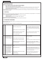
ENGLISH
TABLE OF CONTENTS
1.
2.
3.
4.
5.
6.
7.
8.
9.
GENERAL INFORMATION
DESCRIPTION AND TECHNICAL FEATURES OF FANS
GENERAL SAFETY WARNINGS
TRANSPORT, ACCEPTANCE AND STORAGE
INSTALLATION AND START-UP
MAINTENANCE AND CLEANING
STOP AND DRAINAGE
DISPOSAL
OPERATING PROBLEMS
1. GENERAL INFORMATION
Carefully read the instructions contained in this manual.
Special attention should be paid to the sections following the wording WARNING as, if not complied with, can cause
injuries to people and/or damages to the fan.
Note: store the manual for future reference. We reserve the right to improve and make changes to the manual, products and
accessories without any obligation to update previous productions and manuals. This manual, which applies to all ranges of fans,
!"!#$$% &'"()*$%&+&", +-"+-&"./0123045"61//.7488/289:");"+-&"!$&( <"("=>?@&A
SCOPE AND RELEVANCE OF THIS MANUAL
This manual, produced by the manufacturer, is an integral part of the fans; as such, the manual must always be kept with the fan
until the fan is scrapped and it must be easily available for its quick consultation both by installers and users. Should the machine
be sold, the manual must be given to the new owner as an integral part of the fan. Before starting any operation with or on the fan,
it is compulsory for the staff involved to carefully read this manual. Should this manual go missing, get damaged or partly illegible,
a new copy must be requested to the approved retailer, or directly to the manufacturer, and it must be checked that the date of
the change is earlier than the date of purchase of the machine. This manual has been produced in order to ensure a safe installation and use of the fans and it contains safety warnings and information to avoid accidents at work; therefore, the instructions it
contains must be fully and strictly applied. Furthermore, these instructions do not represent the only procedures to be followed to
ensure safety; each operation carried out on moving and/or live parts such as installation and maintenance operations requires
!$&( >%"(>=&"+)"B&"+>C&?D">?'"*#!+"B&"(>== &'")#+")?%E"BE"F#>% <"&'">?'"!# +>B%E"+=> ?&'"!+>;;A".-&"!>;&+E"=&@#%>+ )?!"&?;)=(&'"BE"
current standards must be strictly adhered to by all the operators of the machine.
2G./H"F#>% <"&'"!+>;;" !"=&@>='&'">!"!+>;;",-)"->!">"!$&( <"("+&(-? (>%"C?),%&'@&" ?">&=>#% (">?'"&%&(+= ("!E!+&*"()*$)?&?+!A
Any future changes made to the safety regulations must be acknowledged and implemented. This manual contains all the information related to all the fans, i.e. not only standard fans, but also specially designed fans. As it is impossible to know beforehand
all different and potential designs or changes which differ from the standard product, the manufacturer shall be responsible for
adding the required enclosures to this manual.
INTRODUCTION
.-&";>?!"(>?"B&"#!&'"+)"->?'%&"I"),");"(%&>?")="!% @-+%E"'#!+E"> ="J#?%&!!")+-&=, !&"!+>+&'KD">'-&= ?@"+)"+-&")$&=>+ ?@"()?' + )?!"
shown in the technical catalogues and in the technical datasheet; they can also be used in more complex systems, machines or
plants. All fans can also be manufactured in special versions, which must be previously agreed with the manufacturer. Using the
fan separately from the systems it is built in should be avoided; should this requirement arise, please contact the manufacturer.
The correct operation and life of the fans requires a number of planned checks and maintenance operations described later in
the manual.
2. DESCRIPTION AND TECHNICAL FEATURES OF FANS
CENTRIFUGAL FANS
In the centrifugal (or radial) fans, the air enters the impeller horizontally and is radially discharged in a scroll-shape housing. Their
$&=;)=*>?(&" !"!# +>B%&";)="*&' #*")="%),"> ="I"),!">?'";)="*&' #*")="- @-"$=&!!#=&!A".-&"$&=;)=*>?(&");"&>(-";>?" !"!-),?" ?"
the technical catalogues. The range includes centrifugal fans with impeller with forward curved blades, impellers with backward
curved blades and impellers with radial blades. The range of centrifugal fans includes standard versions, suitable to handle clean
or slightly dusty air with a temperature between -20°C and +40°C, or special versions. Such features are described in the technical catalogues and in the enclosed technical datasheet, which must be consulted to identify the suitability of the fan to handle the
I"# '"+=&>+&'"BE"+-&"$%>?+",-&=&"+-&";>?", %%"B&" ?!+>%%&'A"
The fans with forward curved blade and radial blade impellers must always be operated when connected to pipes or equipment
,-)!&"=&! !+>?(&"=&'#(&"+-&"I"),"=>+&" ?")='&="+)"=&>(-"+-&"(#==&?+" ?$#+"L>%#&!"()*$>+ B%&", +-"+-&"L>%#&!"J>*$M=&"N"4K"$= ?+&'"
)?"+-&"&%&(+= ("*)+)="?>*&$%>+&A"6-)#%'"+-&";>?")$&=>+&">B)L&"+-&"?)* ?>%"I"),"=>+&"L>%#&"J, +-"B&%%"*)#+-KD"+-&"*)+)=",)#%'"
)L&=%)>'D"%&>' ?@"+)"$)!! B%&";>#%+!A".-&=&;)=&H" ;"+-&"( =(# +"=&! !+>?(&"->!"B&&?",)=C&'")#+D"+-&";>?", %%"@&?&=>+&"+-&"=&F# =&'"I"),"
rate and the motor will use the power shown in the nameplate. If the circuit resistance is higher than the calculated resistance, the
;>?", %%"@&?&=>+&">"%),&="I"),"=>+&"+->?"+-&"=&F# =&'"L>%#&">?'"+-&"*)+)=", %%"'=>,"%&!!"$),&=A"3;"+-&"( =(# +"=&! !+>?(&" !"%),&="+->?"
+-&"(>%(#%>+&'"=&! !+>?(&D"+-&";>?", %%"@&?&=>+&">"- @-&="I"),"=>+&"+->?"+-&"=&F# =&'"L>%#&">?'"+-&"*)+)=", %%"'=>,"*)=&"$),&=A"
The fan with backward curved blade type impeller can also operate with circuits which generate lower resistances than those
Pag. 13
ENGLISH
(>%(#%>+&'", +-)#+"+-&"= !C");"B#=? ?@"+-&"*)+)=">!"+-&E" ?-&=&?+%E"')"?)+"! @? <"(>?+%E" ?(=&>!&"+-&"I"),"=>+&",-&?"+-&"( =(# +"=&! N
stance is reduced. These fans draw the maximum power when they approach the highest performance value. It is recommended
to install on the circuit a regulating shutter, to be set up when starting the system. For further information, please read the technical
catalogues.
AXIAL FANS
4O >%";>?!";&>+#=&">?">O >%"> ="I")," ?">"P(=)!!"I"),Q"()?<"@#=>+ )?A".-& ="$&=;)=*>?(&" !"!# +>B%&";)="*&' #*")="- @-"> ="I"),!">?'"
for medium or high pressures. The performance of each fan is shown in the technical catalogues. The range of axial fans includes
standard versions, suitable to handle clean or slightly dusty air with a temperature between -20°C and +40°C, or special versions.
Such features are described in the technical catalogues and in the enclosed technical datasheet, which must be consulted to
'&?+ ;E"+-&"!# +>B % +E");"+-&";>?"+)"->?'%&"+-&"I"# '"+=&>+&'"BE"+-&"$%>?+",-&=&"+-&";>?", %%"B&" ?!+>%%&'A"R>!&'")?"+-& ="()?!+=#(+ )?D"
they can essentially be divided in two types:
Ducted axial fan: consisting of an impeller and a motor mounted in a cylindrical casing; the fan is driven directly from the motor
(direct coupling) or by means of pulleys and belts (indirect coupling)
Wall-mounted axial fan: with directly coupled impeller and motor mounted on a panel or ring.
For further information, please consult the technical catalogues.
3. GENERAL SAFETY WARNINGS
ASSESSING SAFETY CONDITIONS
The fans can be installed in 4 different working conditions:
S"
4"T +-";=&&" ?%&+">?'")#+%&+"J?)+"'#(+&'K
S"
R";=&&" ?%&+">?'"'#(+&'")#+%&+
S"
0"'#(+&'" ?%&+">?'";=&&")#+%&+
S"
8"'#(+&'" ?%&+">?'")#+%&+"
SAFETY NETS
!"#$#%&'()*'+,-./,01.2*2'0,--31'4-35'1)*'167*'3/'8'-,9':-;1,99,1:3-',-<'1)*2*/32*';.779:*;'1)*'=.,2<;'>/32':-9*1',-<?
32'3.19*1@'3-'0.;13+*2A;'2*B.*;1C'5)3':;'2*;73-;:D9*'/32',;;*;;:-='1)*';6;1*+';,/*'03-<:1:3-;E'F)3.9<'31)*2'167*;'3/'
=.,2<;'D*'2*B.:2*<C'1)*'8'-,9':-;1,99*2C'32'5)3*G*2',01;'3-'):;'D*),9/C'+.;1'0,226'3.1','2:;4',;;*;;+*-1';7*0:8'0,996'2*9,1*<'
to the type of installation required and therefore insert the suitable safety systems according to the type of application.
In order to ensure full compliance with Machine Directive 2006/42/EC these systems must be well built, in order to avoid
,-6'2:;4'3/':-H.26',-<'+.;1'D*'8'I*<';*0.2*96'D6'2*B.:2:-=',';7*0:,9'1339'13'2*+3G*'1)*+E'
.-&"$=)L ! )?");"!>;&+E"?&+!"(->?@&!"+-&">&=>#% ("&;<"( &?(E");"+-&";>?H">%%"%)!!&!");"%)>'D" ?(%#' ?@"+-)!&"@&?&=>+&'"BE"+-&"!>;&+E"
nets or by other accessories, must be assessed at the design stage according to the speed, the air density, the temperature and
all other issues which contribute to change their impact in the system.
R)+-"+-&"<"?>%"#!&=">?'"+-&" ?!+>%%&="*#!+"+>C&" ?+)">(()#?+")+-&="+E$&!");"= !C!D"*)=&"!$&( <"(>%%E"+-)!&"(>#!&'"BE";)=& @?"B)' &!"
entering the fan, or by mixtures different from those allowed. It is also necessary to take into account other risks during the routine
and unscheduled maintenance operations, which must be carried out safely, by disconnecting or isolating the motor power supply,
, +-"!# +>B%&"!>;&+E"'&L (&!">?'", +-")+-&="$=&(>#+ )?!"!$&( <"&'" ?"*)=&"'&+> %!" ?"+-&";)%%), ?@"!&(+ )?!D",- (-"% !+"+-&"!>;&+E"
warnings and maintenance sections.
WARNING! Fitting safety nets does not fully avoid foreign bodies from entering the fan. If hazardous bodies or particles
should get mixed up with the treated air, the user must carry out a full risk assessment able to identify their possible dimensions;
if the diameter of the standard safety net is not enough to ensure the minimum safety requirements, the user must take all the
precautionary measures required to avoid any residual risk.
!"#$#%&'J*2:3<:0,996'0)*04'1)*'*/8'0:*-06'3/'1)*'=.,2<;K';)3.9<'1)*6'D*03+*'/,.916'32'133'532-'5):0)'03.9<'-*=,1:G*L
ly affect their operation, they must be replaced. After the installation, all the main technical features of the fan must be checked
(that the guards have not been removed and/or damaged and/or changed) and, if necessary, a global risk assessment for the fan
in relation to its application.
RISKS CAUSED BY IMPROPER USES
S" Do not insert your hands or other parts of the body near moving parts
S" Do not insert your hands or other parts of the body beyond the guards
S" Do not remove, dispose of or change the guards
S" Do not remove, dispose of or change any monitoring devices
S" 8)"?)+"#!&"+-&";>?" ?"&?L =)?*&?+!"' ;;&=&?+";=)*"+-)!&"!$&( <"&'
S" Unauthorised operators are not allowed to carry out any kind of operation on the fan
S" Reset the safety systems before restarting the fan after carrying out operations which required their removal.
S" Make sure that all safety devices are in full working order
S" :>C&"!#=&">%%"+-&"!>;&+E">?'" ?;)=*>+ )?"$%>+&!"<"++&'")?"+-&";>?">=&" ?"@))'"()?' + )?!
S" Securely tighten all drives or adjusting screws
S" The staff who carries out any operation on the fan must use the required PPE
S" Do not use loose clothing
S" 8)"?)+"+)#(-";>?!"#!&'"+)"->?'%&"- @-"+&*$&=>+#=&"I"# '!A
FAN INHERENT RISKS
S" Dragging by moving parts
S" Dragging by the fan inlet
S" Violent ejection of an object entered in the fan through the outlet
S" Risk of burns or scalding caused by very hot outer surfaces of the fan.
S" Risk of breakages for: Too many vibrations
Pag. 14
ENGLISH
Overspeed
Overtemperature
RISKS DURING MAINTENANCE
S" Carry out a routine maintenance plan to avoid structural subsidence and mechanical faults over time
S" When cleaning the impeller, even with the power supply disconnected, the impeller could still move by inertia or by natural
or forced air currents coming from the other equipment connected to the same system: there is therefore a serious risk of
shearing and/or pinching. For this reason, the impeller must be mechanically locked.
It is strictly forbidden:
- to work on the fan whilst in operation
- to remove the guards when the fan is operating
- to work on the fan without disconnecting the power supply.
NOISE
The fan noise levels are stated in dB(A) and are shown in the technical datasheet (enclosed).
WARNING: The user may detect different values from those shown according to the fan operating environment. It is always recommended to isolate the fan from the ground and from the ducting with antivibration mountings and couplings and, when
?&(&!!>=ED"$=)L '&"&;;&(+ L&"!)#?'$=))<"?@"!E!+&*!" ?")='&="+)"$=)+&(+"!+>;;"-&>%+-A
The user and the employer must comply with current legislation in terms of assuring daily protection from excessive noise to all
operators (as required by current European and national standards) and, if needs be, to require as mandatory the use of personal
$=)+&(+ L&"&F# $*&?+"J&>="'&;&?'&=!D"&+(AK">(()=' ?@"+)"+-&")L&=>%%"!)#?'"$=&!!#=&"%&L&%" '&?+ <"&'" ?">"! ?@%&",)=C ?@">=&>">?'"+)"
the daily levels operators are exposed to.
MECHANICAL RISKS
.-&=&">=&"?)"*&(->? (>%"= !C!A".-&";>?" !"*&(->? (>%%E"$=)+&(+&'"BE">(( '&?+N$=&L&?+ ?@"<"O&'");"=&*)L>B%&"@#>='!"<"++&'"+)">%%"
moving parts, in compliance with standards UNI 10615.
The material inlet and outlet openings are protected by the installer or by a grille which avoids people from coming into contact
with moving parts or by another device. In any case, for all maintenance operations, and after making the machine safe, it is com$#%!)=E";)="+-&")$&=>+)="+)"#!&"$&=!)?>%"$=)+&(+ L&"&F# $*&?+A"3+" !";)=B ''&?"+)"!+)$"+-&";>?"B&;)=&"+-&"I"# '" ?! '&" +"->!"=&>(-&'">"
temperature lower than 60°C, to avoid excessive heat from damaging the motor or the monobloc. Should it be impossible to reach
this temperature, external cooling systems must be provided. When the fan is not working, if its internal temperature increases,
the user must use all means available to reduce the temperature to values lower than 60°C before starting up the fan.
Before starting up the fan, make sure all guards are correctly installed. The inspection door must be removed only with special
tools and only when the fan has been stopped.
The maintenance operations must be carried out in totally safe conditions by disconnecting the fan from the motive power. The
manufacturer shall not be responsible for damages to things or injuries to people caused by missing safety devices if, at the time
);")='&= ?@D"+-&"0#!+)*&="')&!"?)+"!$&( <"(>%%E"=&F# =&!"+-&*A"
4. TRANSPORT, ACCEPTANCE AND STORAGE
TRANSPORT
4%%";>?!">=&"$>(C>@&'" ?"(>='B)>='"B)O&!")="<"O&'")?"$>%%&+!"+)"&>!&"+-& ="+=>?!$)=+A".-&"*>?#;>(+#=&="!->%%"B&"=&!$)?! B%&")?%E"
up to the time of loading. Transport must be carried out in total safety; the haulier is therefore responsible for suitably securing the
load. The fan should be moved by using suitable equipment, as prescribed by directive 89/391/EEC and later directives. Manual
->?'% ?@";=)*"+-&"@=)#?'" !"!$&( <"&'"BE"8 =&(+ L&"UV7WVX7//0">?'"%>+&="' =&(+ L&!Y">",& @-+")="Z[C@" !"@&?&=>%%E">((&$+&'",-&?"
lifted below the shoulder but above ground level.
WARNING: When handling objects over long distances and over uneven ground, the impeller must be locked in position
to avoid vibrations from damaging the bearing races. When handling the fans in particularly adverse environments, such as
when travelling on a ship or on uneven grounds, or when lifting the fans with a crane to reach elevated installation sites, all warran+ &!"!#$$% &'", %%"B&()*&"L) '";)="'= L&"$>=+!">?'D"*)=&"!$&( <"(>%%ED";)="B&>= ?@!">?'"*)#?+ ?@!D" ;"+-&E">=&"?)+"!# +>B%E"$=)+&(+&'A"
3;" ?"')#B+D">!C"+-&"*>?#;>(+#=&=A".-&"+=>?!$)=+"$)! + )?"!$&( <"&'"BE"+-&"*>?#;>(+#=&=";)="+-&";>?")=" +!"! ?@%&"()*$)?&?+!"*#!+"
be complied with.
WARNING: Stacking or applying loads onto the fans is strictly forbidden.
ACCEPTANCE
4%%";>?!">=&"+&!+&'D"B>%>?(&'">?'" ?!$&(+&'"B&;)=&"!- $$ ?@A".-&";>?" !" '&?+ <"&'";=)*"+-&"'>+>"$= ?+&'")?"+-&" '&?+ <"(>+ )?"%>B&%"
>;<"O&'"+)"+-&";>?" +!&%;A".-&";>?!">=&"!#$$% &'", +-">"%&@>%%E"=&F# =&'",>==>?+EA".-&",>==>?+E"!+>=+!";=)*"+-&"'&% L&=E"'>+&">?'"
covers all faults caused by poor workmanship or construction faults. If, when the goods are received, damages are noticed, they
must be immediately reported to the haulier and to the manufacturer: the manufacturer shall not be held responsible for damages
caused during transport. Damaged fans should not be used or repaired, as this would make all warranties void. Check that the fan
matches with the order (design, rotation, power and polarity of the motor installed, accessories, etc.); no non conforming returns
will be accepted after installation has taken place.
WARNING: The range of fans is complete with all safety devices in compliance with current standards, available on request (see technical datasheet). The manufacturer shall not be responsible for damages to things and injuries to people
caused by missing safety devices, nor shall it be responsible for any damages caused by misuse and/or failure to adhere
to the instructions described in this manual.
STORAGE
Avoid the fan from being subject to knocks, which could damage it.
Resistance to chemicals: environments containing corrosive substances, however slight, must be avoided.
It is essential to avoid that the fan impeller is not operational for long periods of time, both when stored and whilst the system
where the fan will be built in is set up. During these periods of time, periodically check the fan by manually turning it to avoid
Pag. 15
ENGLISH
bearing damage. The manufacturer shall not be responsible for damages to drive parts caused by prolonged fan inactivity. Do
not store fans near machines which generate vibrations, to avoid the bearings from being subject to the same type of stresses.
Special care must be taken when handling large impellers or shafts, if they are received disassembled for transport reasons, to
avoid balancing problems.
In case of prolonged storage, ensure the fan is protected from dust, humidity and ultraviolet rays.
5. INSTALLATION AND START-UP
INSTALLATION
!"#$#%&'()*':-;1,99,1:3-'+.;1'D*'0,22:*<'3.1'3-96'D6'B.,9:8'*<';1,//E
6+>=+"BE"=&*)L ?@"+-&";>?";=)*" +!"$>(C>@ ?@")=";=)*"+-&"$>%%&+D"+-&?"' !$)!&");"+-&"$>(C>@ ?@">?'");">%%" +!"$>=+!" ?">=&>!"!$&( <"N
cally designated for waste disposal (waste disposal sites etc..). Never leave parts of the packaging and plastic bags within reach
of children or people who are unable to understand the associated dangers. Use personal protective equipment (gloves etc...) as
prescribed by Directive 89/686/EEC and later directives.
User lifting equipment suitable for the fan weight and size.
Use tie rods of suitable length and of the right quantity and latch them in the slots provided on the fan frames. If necessary, use the
*)+)="% ;+ ?@"&E&B)%+!" ?")='&="+)">L) '"%)>'" *B>%>?(&" ;"+-&"*)+)=",& @-+" !"! @? <"(>?+A It is strictly forbidden to lift the whole
fan using only the motor latching points.
8)"?)+"% ;+"+-&";>?";=)*"+-&"!->;+D"+-&"*)+)=")="+-&" *$&%%&=A".-&"*>(- ?&" !"?)=*>%%E"!- $$&'">!!&*B%&'D"<"O&'"+)">"$>%%&+">?'"
always protected from the elements. Only use the latching points provided for lifting the fan by evenly spreading the load. Avoid
uncontrolled rotations.
The weight of each fan is shown in the enclosed technical datasheet.
0-&(C"+->+"+-&" *$&%%&="->!"?)+"B&&?"C?)(C&'")="'&;)=*&'"'#= ?@"+=>?!$)=+D" !"!&(#=&%E"<"O&'"+)" +!"=)+>+ )?"!->;+D" !">B%&"+)";=&&%E"
turn around its axis and that no foreign body is interfering with the impeller operation.
The user must provide a suitable support surface for the dimensions and weight of the fan and well levelled in order to avoid deformations which could damage the frame of the fan.
When installing the fan on steel structures, it is essential to ensure that these structures have a natural minimum frequency hi@-&="+->?"\[]");"+-&";>?"!$&&'A"3?")='&="+)">L) '"+->+"+-&"L B=>+ )?!">=&"+=>?!;&==&'"+-=)#@-"+-&";)#?'>+ )?D" +" !">'L !>B%&"+)"<"+"
>?+ L B=>+ )?"*)#?+ ?@!" ?"!# +>B%&"$) ?+!A".-&";>?"*#!+"B&"<"O&'" ?"+-&"$) ?+!"$=)L '&'"BE"$>E ?@"!$&( >%">++&?+ )?"?)+"+)"'&;)=*"
the structure. The systems connected must be separately supported and must be located on the same axis as the fan entrances
to avoid stresses on the fan with needless tensions which could deform the structure. It is recommended to connect the fan by
means of couplings able to reduce vibrations generated by the fan.
6&(#=&%E"<"O"+-&";>?"BE" ?!&=+ ?@"!(=&,!", +-"!# +>B%&"' >*&+&=">?'"()==&(+%E"+ @-+&?&'D" ?">%%"+-&"<"O ?@"-)%&!"$=)L '&'A
WARNING: when access to entrances (moving parts) is not ducted or protected with other means, a safety net must be
8'11*<':-'03+79:,-0*'5:1)';1,-<,2<'M#'$FN'OPQRR',-<'9,1*2';1,-<,2<;'>,00*;;326';.779:*<'3-'2*B.*;1@E
WARNING: the fan outlet must NOT be located in areas occupied by people or animals, in order to avoid that objects or
impurities, even if small, could be ejected at high speed and cause injuries.
In order to ensure the correct operation of the fan, it is recommended to make sure certain distances are maintained, such as 1.5
times the impeller diameter as the distance from a wall for free mouth inlets, 2.5 times the impeller diameter as distance from the
<"=!+"B&?'";=)*"+-&";>?"B&%%"*)#+-Y"+-&"!>*&">$$% &!";)=")#+%&+")=" ?%&+"'#(+!Y"$%&>!&"?)+&"+->+" +" !">'L !>B%&"+->+"+-&"B&?'!"->L&">"
* ? *#*" ?+&=?>%"B&?'"=>' #!"&F#>%"+)"+-&"$ $&"' >*&+&=A".-&" ?!+>%%&=">?'7)="<"?>%"#!&="*#!+"$=)L '&"+-&"!# +>B%&"*)+)="L&?+ %>+ )?"
equipment when a suitable heat exchange cannot be ensured such as in the event of prolonged inactivity, when the motor works
at high temperatures, or when used by means of frequency regulators. If the motor is not adequately cooled, its features can be
?&@>+ L&%E">;;&(+&'">?'"$)!! B%E"%&>'"+)" +!"B=&>C>@&Y"+-&=&;)=&D" ?"+- !"&L&?+D"+-&"*>?#;>(+#=&=^!",>==>?+E", %%"B&()*&"L) 'D">!"
well as the warranty granted by the motor manufacturer.
WARNING: Do not remove the guards; removing any of the guard even when the machine has stopped can lead to dangerous conditions
!"#$#%&'!<)*2*' 13' 1)*' +:-:+.+' :-;1,99,1:3-' <:;1,-0*K' 5)*-' 7*2/32+:-=' +,:-1*-,-0*' 37*2,1:3-;C' 03-8'-*<' ;7,0*;'
cause hazards and problems.
IT IS FORBIDDEN TO COMMISSION THE MACHINE WITHOUT MAKING SURE IT IS IN PRISTINE CONDITIONS.
Before starting any installation, make sure the machine is safe and, if necessary, make it safe. The fan must be installed by ensu= ?@"+-&"!#==)#?' ?@"!$>(&" !"!#;<"( &?+"+)">%%),"?)=*>%"<"++ ?@7=&*)L ?@D"(%&>? ?@">?'"*> ?+&?>?(&")$&=>+ )?!"+)"B&"(>== &'")#+A
The following guidelines should be adhered to when carrying out the installation:
S" The surface selected to support the fan static, dynamic load and inherent frequency must be level and sturdy. When the inherent fan frequency coincides with the natural frequency of the mounting, both frequencies act alongside each other, leading
+)">"()?' + )?");"=&!)?>?(&H"+-&">*$% +#'&");")!( %%>+ )?!", %%" ?(=&>! ?@%E"@=),"+)" ?<"? +ED">?'"+-&"!+=#(+#=&", %%"B&"!#B_&(+"+)"
ever growing deformations. In this case, the fan mounting must be changed in order to change its natural frequency of resonance. Sometimes, a resonance is generated only in transistors, i.e. when starting or stopping machinery. Resonance must
be avoided whenever possible. For industrial, high speed fans, using reinforced concrete slabs is recommended.
S" ` B=>+ )?"=&'#(+ )?"()*$)?&?+!"*#!+"B&" ?!&=+&'"B&+,&&?"+-&";>?">?'" +!" ?+&=;>(&!"JI"))=">?'"$ $&!K"J!# +>B%E"! a&'">?+ L N
bration mountings and antivibration couplings). The mountings should not be fully squeezed and should be able to support
a basic frame instead of the single fan components. When selecting the mountings, it is recommended to contact the ma?#;>(+#=&=A"3?"?&>=%E">%%"(>!&!D"+-&";>?!">=&"!#$$% &'"$=&>!!&*B%&'">?'"+-&=&;)=&D"B&;)=&" ?!+>%%>+ )?D" +" !"!#;<"( &?+"+)"(-&(C"
the tension of any belts, the condition of the bearings, the level of the fan and, generally speaking, all components. If the
fan should be shipped disassembled for transport reasons, the manufacturer must enclose suitable instructions to correctly
>!!&*B%&" +Y"+-&">!!&*B% ?@")$&=>+ )?"*#!+"B&"(>== &'")#+"BE">"F#>% <"&'"$&=!)?A".-&"'&! @?">?'"&O&(#+ )?");"+-&"()??&(+ )?"
between the fan and the power mains must be carried out by an experienced electrician. Beyond 5.5kW, a star delta, inverter
)=")+-&="+E$&");"@=>'#>%"!+>=+N#$"*#!+"B&"<"++&'A"3+" !"=&()**&?'&'"+)"<"+">"(-)C&="L>%L&"+)"=&'#(&"+-&"!+>=+N#$"$),&=" ?$#+A"
The fans can have very long start-up times and power input peaks equal to the electric motor nameplate amperage highest
Pag. 16
ENGLISH
multiplier; the whole electrical system must therefore be sized in relation to the duration and start-up power inputs.
ELECTRICAL CONNECTION
!"#$#%&'()*'*9*012:0,9'03--*01:3-'+.;1'D*'0,22:*<'3.1'D6'B.,9:8'*<';1,//E
Check that the power voltage values printed on the motor nameplate match with the data on the power line it is connected to. To
connect the motor, refer to the electrical diagram included in the connection box.
The user must electrically connect the fan to earth: a correct earthing of the motor and the controlled machine avoids tensions and
&''E"(#==&?+!" ?"+-&"B&>= ?@!A"3+" !"=&()**&?'&'"+->+"+-&"*)+)=!"()?+=)%%&'"BE"*&>?!");">?"&%&(+= (";=&F#&?(E" ?L&=+&=">=&"<"++&'"
with PTC protection thermistors against motor overtemperatures. Using electrical frequency converters can increase vibrations
and noise levels.
WARNING: in case a fan is installed away from the control panel and/or location, a service multipole switch must be
provided near the fan itself (accessory supplied on request). In fact, routine maintenance operations may require the fan guards
to be removed. Given the high risk associated to this condition, in compliance with Standard EN ISO 12499 relating to fan me(->? (>%"!>;&+ED">?)+-&="!, +(-"*#!+"B&"<"++&'"?&>="+-&";>?"+)">%%),"*> ?+&?>?(&"&?@ ?&&=!"+)"' =&(+%E"()?+=)%"+-&"$),&="!#$$%E"
connected to the fan.
Select the safety system and the power cables (voltage reduction during the start-up stage must be less than 3%) according to the
+&(-? (>%";&>+#=&!"$= ?+&'")?"+-&"*)+)="?>*&$%>+&A"3?"+-&"&L&?+");"<"=&D"+-&"=>?@&");";#*&!">?'"-&>+"&O+=>(+)=";>?!"*#!+"B&"<"++&'"
with an automatically and separately activated safety electrical system. Make the connection according to the diagram shown on
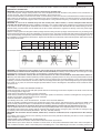
+-&"?>*&$%>+&")="()?+> ?&'" ?"+-&"+&=* ?>%"B)OA". @-+&?"+-&"?#+!"<"++&'")?"+-&"+&=* ?>%!D"(>B%&"&?'!">?'"$),&="(>B%&!"+)"+-&"+)=F#&"
value (Nm) shown below.
Terminal
M4
M5
M6
M8
M 10
M 12
M 14
M 16
Steel
2
3,2
5
10
20
35
50
65
Brass
1
2
3
6
12
20
35
50
8)"?)+" ?!&=+",>!-&=!")="?#+!"B&+,&&?"*)+)="(>B%&"&?'!">?'" ?$#+"(>B%&!"&?'!"J<"@#=&"B&%),KA"
WARNING: it is compulsory for the installer to connect the fan to the electrical power supply and to install it in the environment where it will be used in compliance with current standards (IEC 60364). Thermal cutouts: check the type of cutout
installed before carrying out the connection; for thermistors, a special release relay is required.
WARNING: To use thermal cutouts, take the required measures in order to avoid hazards associated with a sudden restart. Any anti condensation resistors (heaters) must be supplied by separate power lines. They cannot be powered with the motor
in operation. Do not connect the motor in case of doubts on how to interpret the connection diagram or, if the connection diagram
is missing, contact the manufacturer. All motors used are full voltage direct start type or delta-triangle start type for powers higher
than 5.5kW. In any case, the connection diagram provided with the motor is the diagram to be followed, which is inside the motor
connection box.
START-UP
OPERATIONS TO CARRY OUT BEFORE START-UP:
Check the tightness of all nuts and bolts (with special attention to the locking screws of the impeller on the shaft, of the motor and
the mountings) and the alignment.
Check that the fan blade turns freely by turning it manually.
0-&(C"+->+">?E"!-#++&=!")="I"),"=>+&"=&@#%>+)=!">=&" ?"+-&")$&?"$)! + )?";)=">O >%";>?!D"(%)!&'";)="(&?+= ;#@>%";>?!A"8#= ?@"+-&"!+>=+N
up stage, this operation avoids dangerous motor overloads.
Check the lubrication of moving parts.
For indirectly driven fans, check the belt tension, as shown in the technical datasheet.
0-&(C"+-&" ?!#%>+ )?"=&! !+>?(&"B&+,&&?"+-&", ?' ?@!">?'"&>=+-D",- (-"*#!+"B&D", +-", ?' ?@">+"Z\b0D"- @-&="+->?"X[:cA"5),&="
values normally indicate that there is condensation in the windings. Should this happen, ask a specialised company to dry it.
WARNING: Do not touch the terminals during and immediately after the measurement as the terminals are live.
Note the impeller direction of rotation shown by the arrow (if provided) located on the impeller blades or on the fan itself.
The installer must interface the machine with the required start-up/stop controls, emergency stop, reset after an emergency stop
by complying with current standards (EN 60204-1, EN 1037, EN 1088, EN 953).
!"#$#%&'()*'/,-'/2,+*'+.;1'D*'*,21)*<K'/.21)*2+32*C':1'+.;1'D*'G*2:8'*<'1),1',99':1;'03+73-*-1;'),G*'1)*';,+*'73L
tential.
The installer must connect the fan to the earthing circuit and check the potential is effectively the same on all its components
before starting the machine.
OPERATIONS TO BE CARRIED OUT AFTER START-UP:
Check that the direction of rotation matches with the direction shown by the arrow.
0-&(C"+->+"+-&" ?$#+"(#==&?+"')&!"?)+"&O(&&'"+-&"(#==&?+"!-),?")?"+-&"$=)'#(+" '&?+ <"(>+ )?"%>B&%">?'7)="*)+)="?>*&$%>+&A".)"
have a reliable information, allow a reasonable period of stabilising time. In the delta/triangle connection, the reading must be car-
Pag. 17
ENGLISH
ried out upstream of the change-over switch; if this is not possible, detect the live current on any of the six wires at the terminal box
and multiply this value by 1,73. Avoid consecutive start-ups of the motor as this would cause continuous overloads, and overheat
the electrical parts. Before start-up, allow enough time to cool down.
0-&(C"+-&"B&>= ?@"+&*$&=>+#=&!">;+&="+-&"<"=!+"-)#=!");")$&=>+ )?D">!"+-&!&">=&"+-&"*)!+"(= + (>%A"3;"?&(&!!>=ED"!+)$"+-&";>?">?'"
restart it only after reaching the ambient temperature. Then check that the temperature is lower than the previously measured
temperature.
By means of a vibrometer, check that the vibrations are not excessive by referring to the following paragraph.
After a few hours of operation, check that the vibrations have not slackened the tightness of the nuts.
IMPELLER BALANCING AND VIBROMETRIC CHECK
4%%"+-&" *$&%%&=!" ?!+>%%&'")?"+-&";>?!">=&" B>%>?(&'" ?"()*$% >?(&", +-"!+>?'>='"36G"XdeVd"P3?'#!+= >%";>?!"N"6$&( <"(>+ )?!";)="
B>%>?(&"F#>% +E">?'"L B=>+ )?"%&L&%!QD">?'", +-"!+>?'>='"36G"XVd[NXA
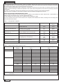
The fan vibration level is then tested, still in compliance with standard ISO 14694.
The in situ vibration level check must be carried out in compliance with standard ISO 14694, according to the fan category and
within the limits shown below.
.>B%&"X"f"g>?">$$% (>+ )?"(>+&@)= &!
Applications
Examples
Motor power limits
Application
category
Residential use
Ceiling-mounted, wall-mounted and AC
, ?'),N<"++&'";>?!
h[DX\
i[DX\
BV-1
BV-2
HVAC and agricultural use
Ventilation and air conditioning of residential
and commercial buildings
hWDj
iWDj
BV-2
BV-3
Industrial and energy production
processes, etc.
4 ="<"%+&= ?@"=))*!D"* ?&!D"()?L&(+ )?!D"()*B#N
sted air, pollutant control, wind tunnels
hW[[
iW[[
BV-3
See ISO 10816-3
:>= + *&">?'"+=>?!$)=+"<"&%'!
Locomotives, road transport vehicles, cars
hX\
iX\
BV-3
BV-4
Transit/tunnel
Underground emergency ventilation, tunnel
and garage fans, tunnel jet fans.
hj\
ij\
None
BV-3
BV-4
BV-4
Petrochemical process
Noxious gases, process fans.
hWj
iWj
BV-3
BV-4
IT chip production
Sterile environments
None
BV-5
.>B%&"Z"f"L B=>+ )?"% * +!";)="+&!+!"(>== &'")#+"in situ
Condition
Start-up
Alarm
Stop
Note 1
Application
category
Hard mounting
mm/s
Flexible mounting
mm/s
peak
r.m.s.
peak
r.m.s.
BV-1
14,0
10
15,2
11,2
BV-2
7,6
5,6
12,7
9,0
BV-3
6,4
4,5
8,8
6,3
BV-4
4,1
2,8
6,4
4,5
BV-5
2,5
1,8
4,1
2,8
BV-1
15,2
10,6
19,1
14,0
BV-2
12,7
9,0
19,1
14,0
BV-3
10,2
7,1
16,5
11,8
BV-4
6,4
4,5
10,2
7,1
BV-5
5,7
4,0
7,6
5,6
BV-1
Note 1
Note 1
Note 1
Note 1
BV-2
Note 1
Note 1
Note 1
Note 1
BV-3
12,7
9,0
17,8
12,5
BV-4
10,2
7,1
15,2
11,2
7,6
5,6
10,2
7,1
The switching off levels for fans belonging to BV-1 and BV-2 grade application must be established according to
their history
3+" !"=&()**&?'&'"+)"#!&"+-&"P=A*A!AQ"L>%#&!"f"`>%#&!" ?"**7!"#?<"%+&=&'
Pag. 18
ENGLISH
6. MAINTENANCE AND CLEANING
:> ?+&?>?(&")$&=>+ )?!");";>?!">=&"=&%>+ L&%E"! *$%&D"B#+"+-&E"!+ %%"=&F# =&"=)#+ ?&")$&=>+ )?!"> *&'"+)"*> ?+> ?"+-& ="&;<"( &?(E");"
>%%"+-& ="()*$)?&?+!">?'"+)">L) '"'>*>@&!",- (-",)#%'"?&@>+ L&%E">;;&(+"+-& ="@))'",)=C ?@")='&=">?'"$&)$%&^!"!>;&+EA".-&" ?+&=N
val of maintenance operations depends on the fan effective operating conditions. In ideal and continuous operating conditions, it
!">'L !>B%&"+)"!#B_&(+"+-&";>?"+)">"*> ?+&?>?(&")$&=>+ )?">;+&="+-&"<"=!+"X[["-)#=!");")$&=>+ )?D"+-&?"&L&=E"W[[["-)#=!";)="' =&(+%E"
coupled fans.
If the technical datasheet contains a table summarising the planned maintenance operations which states the frequency they
should be carried out at, strictly follow these instructions. Before starting any maintenance operations, stop and drain the fan and
put the machine in a safe condition (see chapter 7). When removing any dust from inside the machine, make sure not to disperse
it in the surrounding environment.
Impeller: it is recommended to constantly check that the impeller is clean. If layers of material, dust, greasy substances etc. should
build up on the impeller, they would cause it to get unbalanced and would lead to damages to drive parts and/or to the electric
*)+)=A"8#= ?@"+-&"(%&>? ?@")$&=>+ )?!D">%%"$>=+!");"+-&" *$&%%&="*#!+"B&"(%&>?&'Y">?E"=&! '#&!" ?"()?<"?&'">=&>!"()#%'"%&>'"+)"*)=&"
#?B>%>?(&");">"*)=&"&L&?"%>E&=");"' =+D"+-&=&;)=&"+-&"(%&>? ?@")$&=>+ )?"*#!+"B&"+-)=)#@-A":)=&"!$&( <"(>%%ED";)=" *$&%%&=!", +-"
curved blades, conveying statically charged materials or containing adhesives or resins can cause a build-up on the back of the
blades. Therefore a thorough cleaning is recommended to make sure any residual dirt is evenly spread, thus avoiding any unba%>?(&A"3;"+-&"(%&>? ?@")$&=>+ )?" !"=&F# =&'"+))");+&?D" !" +">'L !>B%&"+)"=&$%>(&"+-&" *$&%%&=", +-">?" *$&%%&=", +-">"!$&( >%%E"$=)<"%&'"
blade. For more information, contact the manufacturer. When abrasive powders or highly corrosive air are taken in by the fan, the
vibrations may be caused by the wear and tear of the impeller. In this case, replace it with a genuine part. The manufacturer shall
not be responsible for damages occurring to drive parts and/or to the motor caused by dirt on the impeller.
Scroll: clean the internal parts by removing any foreign body; check the condition of the welding and their resistance to oxidation.
Motor: the motor must always be kept in clean conditions so that it does not have any traces of dust, dirt or other impurities.
Periodically check that it works without vibration or abnormal noises, that the ventilation circuit inlet (if present) is not obstructed,
leading to potential overheating of the windings.
R&>= ?@!H"+-&"*>_)= +E");"*)+)=!",&"#!&">=&"<"++&'", +-"% ;&"%#B= (>+&'",>+&=+ @-+"B&>= ?@!D",- (-"')"?)+"=&F# =&"%#B= (>+ )?A".-& ="% ;&"
varies according to the actual operating conditions (number of start-ups etc.) and the operating ambient conditions (temperature,
presence of dust etc.). Our fans are sized in order to give at least 20,000 hours of operation (according to the model) for continuous operation, in ideal environment and conditions. However, we recommend the bearings to be replaced every 4 years with
bearings with the same features as the original bearing. For models requiring a periodic lubrication, read the technical manual,
which contains the lubricating instructions and intervals. If in doubt, contact the manufacturer. Nuts and bolts: check that they
are not oxidised; oxidation will jeopardise their functionality; replace them with identical nuts and bolts and systematically tighten
them.
Check the condition of the seals after removing all bolted parts (inspection door, disk etc). When the seals no longer ensure the
correct tightness, they must be replaced.
During the cleaning stages, the user must select suitable products to the type of system and to the safety datasheet of the conveyed product.
Before starting the fan, make sure no metal foreign bodies are left inside the fan body.
Repeat the required operations before and after start-up (chapter 5).
CHECKING MINIMUM SAFETY DISTANCES
At each maintenance operation, it must be checked that all the spaces between the impeller and the mouthpiece, between the
back of the impeller and the adjacent wall, between the shaft passage and the seal have not decreased or changed in any way.
S"
.-&"!(=&,!"()#%'"->L&"()*&"%))!&">?'">";>?"=&>% @?*&?+"*>E"B&"=&F# =&'
S"
.-&";>?"*>E"->L&"@)+"'&;)=*&'">?'"!)*&"()*$)?&?+!")="+-&",-)%&";>?"*>E"?&&'"=&$%>( ?@A"
WARNING: If the technical datasheet contains a table with the minimum values between spaces, these values must be
carefully checked.
ROUTINE MAINTENANCE
In a typical fan, the planned maintenance operations are the bearing lubrication operations (if they are not watertight) and the belt
tensioning operations. Before starting the maintenance operations, make sure the machine is safe to operate.
Carry out maintenance operations only with the machine switched off. As for maintenance operations, the user must ensure that
the tools and equipment used are of a suitable class for the environment. If the machine maintenance requires some hot processes, thoroughly clean it before starting the work.
UNSCHEDULED MAINTENANCE
g>?"!$&( >%">$$% (>+ )?!"!)*&+ *&!"=&F# =&"!$&( <"("#?!(-&'#%&'"*> ?+&?>?(&")$&=>+ )?!D"!#(-">!"=&$%>( ?@"+-&" *$&%%&=")="+-&"
motor.
9?!(-&'#%&'"*> ?+&?>?(&")$&=>+ )?!"*#!+"B&"(>== &'")#+")?%E"BE"F#>% <"&'"!+>;;D",-)"*#!+";)%%),"!$&( <"(" ?!+=#(+ )?!"$=)L '&'"BE"
the manufacturer, according to the type of fan and operation.
After carrying out any type of unscheduled maintenance operation, the start-up procedures described in chapter 5 must be repeated.
7. STOP AND DRAINAGE
WARNING:
S" T-&?"- @-"+&*$&=>+#=&"I"# '!">=&"()?L&E&'D"+-&";>?"*#!+"B&"=&;= @&=>+&'")=" +!"()?+&?+"*#!+"B&"* O&'", +-"()%'"> ="B&;)=&"
!+>=+ ?@">?E")$&=>+ )?H"+-&")$&=>+)="()#%'"@&+"B#=?+",-&?"+)#(- ?@"$>=+!");"+-&";>?")=",-&?"()* ?@" ?+)"()?+>(+", +-">?E"I"# '"
left inside
S" If chemicals are conveyed, which could collect at the bottom, draining plugs must be placed under the fan and the fan must
Pag. 19
ENGLISH
be drained before opening it.
MAKING THE MACHINE SAFE
g=)*"?),")?D"P*>C ?@"+-&"*>(- ?&"!>;&Q"&?+> %!"+-&";)%%), ?@")$&=>+ )?!H
S"
:>C&"!#=&"+-&"*>(- ?&" !"' !()??&(+&'";=)*">%%"$),&="!#$$% &!
S"
:>C&"!#=&">%%"*)L ?@"$>=+!"->L&"()*&"+)">";#%%"!+)$"
S"
T> +"#?+ %"+-&" ?+&=?>%">?'"&O+&=?>%"+&*$&=>+#=&");"+-&"*>(- ?&"->!"=&>(-&'">"L>%#&",- (-" !"?)+"+))"-)+"+)"+-&"+)#(S"
k=)L '&"!# +>B%&"% @-+ ?@";)="+-&">=&>">=)#?'"+-&"*>(- ?&"JBE"@ L ?@"+-&")$&=>+)=!"&%&(+= (>%"% @-+!D" ;"?&(&!!>=EK"
S"
:&(->? (>%%E"%)(C"#$">%%"*)L ?@"$>=+!A"
For any operation to be carried out on the machine (maintenance and cleaning), the operators must wear the required personal
protective equipment (PPE).
8. DISPOSAL
T-&?"+-&";>?"=&>(-&!"+-&"&?'");" +!"% ;&D"+-&"<"?>%"#!&=")=",-)&L&=">(+!")?"- !"B&->%;"*#!+"()==&(+%E"' !$)!&");" +A".- !")$&=>+ )?"
requires some important operations to be carried out:
S"
!&$>=>+&"+-&"&%&(+= (>%"()*$)?&?+!";=)*"+-&"*&(->? (>%"()*$)?&?+!
S"
'=> ?"+-&"%#B= (>?+!
S"
!&$>=>+&"' ;;&=&?+"*>+&= >%!"!#(-">!"$%>!+ (!D"!+&&%D"()$$&="&+(A
All materials must be separately disposed of
Dispose of the materials in special recycling areas; do not litter the environment.
9. OPERATING PROBLEMS
R&>=" ?"* ?'"+->+D" ;" >?">&=>#% (" !E!+&*" !" ?)+",)=C ?@D"+-&=&"*>E" B&" *)=&" +->?")?&"(>#!&A"4%%" (>#!&!" *#!+" B&" '&?+ <"&'">?'"
systematically removed.
Some possible faults, causes and solutions for aeraulic systems:
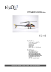
9.1
9.2
9.3
8 ;<"(#%+"!+>=+N#$
Power input higher that
the value shown on the
'&?+ <"(>+ )?"%>B&%">?'7
or the motor nameplate.
4 ="I"),"=>+&"+))"%),A
At the nominal rotation
speed, the input power
is reduced, especially
for the centrifugal fans
with forward curved
blades or with radial
blades. The power
input is less affected for
centrifugal backward
blade fans.
Pag. 20
Reduced power voltage.
Check the motor nameplate data
Motor start-up torque too low.
Close the shutters until full speed is reached
(does not apply to axial fans). If this is case,
replace the motor with a more powerful motor.
Unsuitable fuses for the start-up conditions.
Replace.
Unsuitable assessment of the fan inertia
and of the coupling components.
Work out again the inertial momentum and, if
?&&'!"B&D"<"+">"?&,"*)+)=")?"+-&";>?A"
Too much power drawn.
See 9.2
Rotation speed too high.
Replace the motor and/or the pulleys and/or
redesign the system.
Air density higher than the project data.
As above.
The fan works with excessive pressure.
Redesign the system or replace the type of fan.
The motor turns at a lower speed than its
normal rotating speed.
Check the power voltage and, if needs be,
rectify it. Check that the winding is not defective
and, if so, repair or replace.
Obstructed pipes and/or blocked up inlet
points.
Clean pipes and hoods, check shutter position.
Rotation speed too low.
Check power voltage and check motor connections, check drive ratios; if needs be, rectify
it. Check that the belts do not slip; if they do,
restore their correct tension.
Working pressure higher than the design
!$&( <"&'"$=&!!#=&A
Design error; replace the motor and/or the
pulleys, replace and/or adapt the circuit.
Blocked up impeller.
Clean the impeller.
ENGLISH
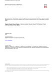
9.4
9.5
9.6
9.7
9.8
4 ="I"),"=>+&"+))"- @-A"
A the nominal rotation
speed, this causes
the fans with forward
curved blades and with
radial blades to draw
too much current.
Pressure too low
Air pulses.
Reduced performance
after a period of satisfactory operation.
Too much noise. Normally, all fans generate
noise, but this should
Reversed direction of rotation.
Check the electrical connection. Check the
winding connection on the motor terminal box.
GL&=%)>'&'"<"%+&=A
0%&>?")="=&$%>(&"+-&"<"%+&=A
Inlet turbulence in the same direction of
rotation as the impeller.
3?!+>%%"I"),"!+=> @-+&?&=!A"
Change of sections, tight and close bends,
sudden widening or bends which do not
allow the dynamic inlet pressure to be normally recovered.
Design error; change or replace the circuit.
Rotation speed too high.
Check the power voltage and, if needs be,
rectify it. Check the drive ratio, if needs be,
rectify it.
Estimated circuit load losses too high.
Partly close the shutters and/or reduce speed
until the required performance is achieved.
Wrong direction of rotation of the impeller
Check the direction of rotation. A reversed,
(#=L&'")="I">+"B%>'&" *$&%%&=",- (-"+#=?!" ?"+-&"
reverse direction of rotation operates like an
impeller with forward curved blades and this
,)#%'"(>#!&">?"&O(&!! L&"I"),"=>+&D">?'"'=>,"
too much power. If this is case, restore the
correct direction of rotation.
Air leaks or open access doors, poorly manufactured or badly installed pipes or components, bypass shutters not fully closed
Check the system by replacing the non conforming components.
Rotation speed too low.
See 9.3
Reversed direction of rotation.
See 9.3
Flow rate higher than the design value due
to incorrect circuit size and/or air temperature different from the temperature considered
in the circuit design.
Change the drive ratios and/or replace the fan,
replace or adapt the circuit.
Damaged impeller.
Check the impeller and, if needs be, replace it
with a genuine part.
.-&";>?")$&=>+&!">+">%*)!+"a&=)"I"),"=>+&"
conditions
Change the circuit and/or replace the fan.
9?!+>B%&"I"),D")B!+=#(+ )?!")="B>'" ?%&+"
connection which creates unstable air inlet
conditions (vortexes).
l&'&! @?"+-&" ?%&+"BE"$%>( ?@"'&I"&(+)=!D"(%&>?"
and/or restore the inlet.
4%+&=?>+&"I"),"' !()??&(+ )?">?'"=&()??&(N
tion at a diverging channel walls.
Redesign the circuit and/or replace the fan.
Loss in the fan upstream and/or downstream circuit.
Check the circuit and restore its original conditions.
Damaged impeller.
Check the impeller and, if needs be, replace it
with a genuine part.
Too many revolutions are required to achieve the required performance.
Use of soundproofed casings and/or sound
dampers. Replace the fan with a larger fan able
to give the same performance or with a lower
Pag. 21
ENGLISH
become a worrying
issue when the level
is unacceptable. This
?) !&"(>?"B&" '&?+ <"&'"
as a noise caused by
air, mechanical parts,
electrical buzzing noise
or a combination of
these factors. Whilst
the noise caused by air
can increase because
of obstructions near
the fan inlet or outlet,
an excessive noise is
more commonly caused
by the wrong choice or
installation of the fan.
9.9 Too many vibrations
Pag. 22
peripheral speed.
The impeller scrapes on the enclosure.
0-&(C"+-&"<"++ ?@"$)! + )?");"+-&" *$&%%&=">?'"
the pipes; if needs be, correctly restore their
position.
Bearings worn.
Check the condition of the bearings; if needs
be, lubricate them or replace them with an
identical bearing.
Eccentricity between rotor and stator.
Check that the axis is identical; if needs be,
restore or replace the electrical motor with a
suitable type.
Winding vibrations
Can be reduced with higher quality motors
Positioning in a resonant area
Move the fan or use soundproofed casings
Unbalanced rotating parts.
Check impeller balance; if necessary, reset it to
the values shown in diagram 1. Check the drive
alignment or the pulley balance. Check that the
shafts are straight.
Unsuitable mounting structure: with a natural frequency close to the fan rotation speed
natural frequency.
Strengthen and/or change the natural frequency of the mounting structure by using weights.
Slackened screw connections
Tighten the nuts and bolts
Defective bearings
Check the wear of the bearings (specially the
watertight bearings) and their lubrication.