1
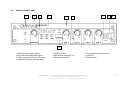
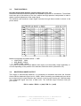
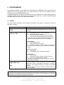
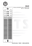
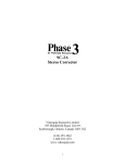
AM 41443
AUTOMIXER
PREAMPLIFIER
User’s Manual
Rel. 1.01
24/09/2007
quattroitalia s.r.l. 35020 ALBIGNASEGO (PD) ITALY, V. delle Industrie 38
Tel. +39.049.862.6724 Fax +39.049.862.6440
E-mail: [email protected] - internet: www.omnya.com
1
SUMMARY
1
FOREWORD
1.1
1.2
1.3
Thanks
The automatic mixer preamplifier
The package contains
2.
DESCRIPTION
2.1
2.2
2.3
Block diagram and description
Front panel of AM41443
Rear panel of AM41443
3.
THE CIRCUIT
3.1
3.2
3.3
3.4
3.5
3.6
3.7
3.8
3.9
Front panel switch
Microphone channel
Tone controls
Master balanced output
Auxiliary balanced output
USB control port
RS232 control port
Daisy-Chain connectors and RS485 port
Internal selections
4
OPERATING MODES
4.1
4.2
4.3
4.4
4.5
Manual
Mixer Stand-alone
Mixer Daisy Chained
Programming and controlling
Master and Slave
5
PROGRAMMING
5.1
5.2
5.3
5.4
5.5
Reset
Indications from the VU-meter
LED for status channel indication
Default settings
Behaviour with the manual selections
6
INSTALLATION
6.1
6.2
6.3
6.4
Mechanical installation
Plugging into the mains
Ground loop
Microphone lines
7
USING THE AUTOMIXER
7.1
7.2
7.3
7.4
Church setup
Conference room setup
Videoconferencing setup
Broadcast uses
8.
TECHNICAL CHARACTERISTICS AND PERFORMANCES
8.1
8.2
List of the controls available for remote control:
Technical Data
APPENDIX
A.1
A.2
A.3
A.4
A.5
A.6
A.7
A8
OPERATING FUNCTIONS
AMB-THR
Last-On
One-On
LOM
NOM
ORG
NOISE GATE
LIMITER
quattroitalia s.r.l. 35020 ALBIGNASEGO (PD) ITALY, V. delle Industrie 38
Tel. +39.049.862.6724 Fax +39.049.862.6440
E-mail: [email protected] - internet: www.omnya.com
2
1.
FOREWORD
1.1 THANKS
Congratulations! You have chosen an Omnya brand product. The automatic mixer and
preamplifier AM41443 is a high technology device engineered to solve numberless
problems with an incredibly easy use. We hope you will be completely satisfied with this
product’s features.
1.2
THE AUTOMATIC MIXER
When installing a P.A. system where loudspeakers and microphones are located in the same
room, two contrasting requirements need to be met: an adequate sound level has to be
achieved to ensure intelligibility, but feedback must not be triggered.
Problems come up especially when several microphones are used, as the installer has to adjust
each of them to the required sensitivity when in use. However, when all the microphones are on,
overall sensitivity increases significantly as well, by 3 dB each time the number of microphones
doubles. We thus have +3dB when going from one to two microphones, +6dB from two to four,
+9dB from four to eight. The sensitivity increase easily moves the system into the feedbacktriggering zone and the overall gain has to be reduced to move back into the safe zone. This
way however, each individual microphone no longer has its optimum sensitivity. In general, the
final setting is a possibly poor compromise, with the significant drawback that, especially in a
reverberating environment, any microphone that is open and not engaged picks up and feeds
reverberated sound into the system: even when feedback is not triggered, the returning sound
tail blurs the direct sound.
AM41443 belongs to a new generation of automatic mixers under the OMNYA brand.
It is a small mixer working both manually and automatically, with a total modularity that avoids
real limits to the number of channels. This also means that more AM41443s can be installed
locally or in different places and controlled through a PC connection or a remote control panel.
It can work as manual or automatic stand-alone or through a USB port controlled mode.
The AM41443 main characteristic is that the audio signal is analog. The high quality
microphone front end maintains a very low distortion and a maximum signal/noise ratio. With
its 20dB headroom it guarantees a perfect result in any condition. This automatic mixer is
produced in a ½ rack unit metallic box.
A powerful microcontroller manages the control functions, the internal functions, the network
supervision and the links with the panel or the controlling PC.
The AM41443 has 3 independent balanced outputs. The main output works through a volume
control on the front panel. The second output, also having a trimmer volume control, can serve
a separate group of amplification devices. The third output can create a chain of several
automatic mixers through a RJ45 shielded connection cable containing the audio and the
control line data.
An output group can be managed by a tri-band equalizer adjusting the curve. The input
channels can be divided into two groups for particular uses such as in broadcast applications
with ambience microphones.
This device works with 24V external batteries and can give power supply up to 5 AM41443
with no need of additional power sources.
The firmware updates available on Internet can be easily installed through the USB port.
1.3 THE PACKAGE CONTAINS
Inside the AM41443 box you will find:
1 AM41443
1 50 cm RJ45-RJ45 connection cable
1 24V 300mA power supply
1 short rack-mounting bracket (long bracket for single mount or support for double mount are
optional)
quattroitalia s.r.l. 35020 ALBIGNASEGO (PD) ITALY, V. delle Industrie 38
Tel. +39.049.862.6724 Fax +39.049.862.6440
E-mail: [email protected] - internet: www.omnya.com
3
2.
DESCRIPTION
The automatic mixer preamplifier AM41443 provides all the fundamental functions typical of
such device and some more features:
•
It opens the engaged microphone channels only, and keeps the others closed (see par.
4.8). In other words, when the signal is generated by the voice of the speaker talking into
the microphone, the channel opens and turns on the signal. In any other case, when the
signal is due to ambient noise or reverberation, the channel stays closed and the signal
is attenuated and not heard.
•
It keeps the mixer's output level at its preset value when the number of open microphone
channels changes (see NOM App.A.5)
Besides, the following functions are also available:
•
•
•
•
•
•
LAST-ON: last activated microphone remains open even if the speaker is silent until a
new microphone is activated
LOM: The number of open microphones can be limited from 1 to 4 for the single device,
from 1 to N for linked devices.
ONE-ON: Microphone channel 1 is activated when any other microphone receives a
signal
PRIO: one microphone channel has the priority over the other microphones.
ORG: a chosen channel forces the closing of other channels which were qualified for
this function
OVR: A channel can be forced open
Other AM41443 features are indicated in sections 8.1-8.2
The logic controlling this device is undoubtedly its fundamental and most important
characteristic. The AM41443 is basically a mixer with a VCA on each microphone channel that
turns the microphone on and off. Normally off, the gate goes on as soon as someone begins
speaking at the relevant microphone. One of the most important problems for an Automixer is
the circuit used to turn the channel on or off. To attain this result the incoming voice signal must
be compared to a reference or threshold signal. The easiest way is the use of a fixed threshold
as in a simple gate (the threshold voltage may actually be adjusted manually but remains fixed
during operation). A fixed threshold does not work: if set low, every unwanted sound picked up
by the microphone will open the channel, if set too high the first syllable of the speech will be
lost.
What is needed is a threshold voltage that automatically follows the ambient noise. Such is the
circuit used by the Automixer where the sum of the signals picked up by all microphones
connected to it is processed to produce the reference threshold signal that represents the
ambient noise. This way what actually turns the channel on is the difference between the direct
sound and the background or ambient sound.
The managing of the functions dedicated to an automatic mixer can be various and different.
The AM41443 is an analog mixer based on a digital control and even if it has a predefined
control mechanism it is open for future implementation of alternative models for the microphone
controls.
The AM41443 features 4 variable gain microphone inputs; phantom power is given to all
microphones at the same time through a front panel switch.
quattroitalia s.r.l. 35020 ALBIGNASEGO (PD) ITALY, V. delle Industrie 38
Tel. +39.049.862.6724 Fax +39.049.862.6440
E-mail: [email protected] - internet: www.omnya.com
4
2.1
BLOCK DIAGRAM AND DESCRIPTION
As shown in the picture the AM41443 mixer can be
used in very different situations thanks to its
particular features. As already said in the
description, this automatic mixer is a digital
controlled analog device. This means that AM41443
can conceive a very high audio purity and has the
advantage to allow both a local and a remote control
on the main functions. Also other processes, as the
channels opening, can be automated following
needs.
The input section has 4 variable sensitivity inputs
and processes signals from –60 dB to line level.
These inputs can be divided into 2 blocks of 2
channels each to control separately (locally or
remotely) the mixing of a number of channels. In this
manner, for example, we can mix on the auxiliary
output all 4 channels while we send only two of them
to the general mixing. This function could be useful
in situations in which a service need ambience
signals for a radio broadcast while the preserved
signals (without the ambience) are sent to the local
reinforcement system.
A tone correction feature can be used before the
master or the auxiliary output. The daisy chain
connection of more AM41443 (up to 24 devices can
be linked) is obtained through a RJ45 connector.
This connection allows the link between the units of
the digital line for the control-information on the
chain and the analog signals producing the mixed
program. The audio signals are directional.
quattroitalia s.r.l. 35020 ALBIGNASEGO (PD) ITALY, V. delle Industrie 38
Tel. +39.049.862.6724 Fax +39.049.862.6440
E-mail: [email protected] - internet: www.omnya.com
5
2.2
AM41443 FRONT PANEL
1
2
3
4
5
7
6
8
9
10
1) AUX2 Auxiliary volume output
4) VU meter and configuration signal
7) USB connection for remote PC control
10) Mode and function selection switch
2) Master volume
5) Microphone input level 1-4
8) External control LED
3) Low-medium-high tone control
6) ON LED
9) Reset button
quattroitalia s.r.l. 35020 ALBIGNASEGO (PD) ITALY, V. delle Industrie 38
Tel. +39.049.862.6724 Fax +39.049.862.6440
E-mail: [email protected] - internet: www.omnya.com
6
2.3
AM41443 REAR PANEL
20
21
22
20) DAISY CHAIN connector
23) RS232 port
26) Sensitivity/filter switch
23
24
21) RCA auxiliary output
24) DC power supply
25
26
22) Master output
25) MICRO-LINE inputs
quattroitalia s.r.l. 35020 ALBIGNASEGO (PD) ITALY, V. delle Industrie 38
Tel. +39.049.862.6724 Fax +39.049.862.6440
E-mail: [email protected] - internet: www.omnya.com
7
3.
THE CIRCUIT
AM41443 is a complete automixer-preamplifier that can drive one or more power amplifiers.
Main features:
• 4 variable sensitivity microphone inputs with 48V phantom power and selectable
high pass filter (see 3.1-3.2)
• General tone control (see 3.3)
• Balanced master output on XLRm connector (see 3.4)
• Balanced auxiliary output on RCA connectors (see 3.5)
• USB control port (see 3.6).
• RS232 serial control port (see 3.7).
• Connector used to link other mixing units through a daisy chain connection (see
3.8).
3.1
FRONT PANEL SELECTION SWITCH
In the default configuration of the device all the switches are lowered. In this condition it
works as an automatic mixer. To be more detailed:
ON
AUTOMIXER
1
2
3
4
OFF
5
PHANTOM
LIMITER
LAST-ON
PRIO-CH1
The first lowered switch shows that the device is operative in the automatic mode, while all
the other functions are deactivated. These functions can be activated putting switches no. 23-4-5 in the ON position.
For example:
to activate LAST-ON push switch no. 3 upward.
to activate phantom power on all microphones put switch no. 5 in the ON position.
The first switch in the ON position shows that the device is in the manual mode, i.e. mixing
every signal without on-board intelligence (as a concert mixer). The other functions (NoiseGate, Future Use, Limiter, and Phantom) can be activated pushing the switches upward
N.B. The first switch position changes the meaning of 2nd and 3rd switch.
quattroitalia s.r.l. 35020 ALBIGNASEGO (PD) ITALY, V. delle Industrie 38
Tel. +39.049.862.6724 Fax +39.049.862.6440
E-mail: [email protected] - internet: www.omnya.com
8
MANUAL
ON
MIXER
OFF
1
2
3
4
5
PHANTOM
LIMITER
(FUTURE USE)
NOISE-GATE
P.S. The AM41443 can be controlled through an external serial connection (see
software user’s manual for the control of AM41443). It is important to remember that
the settings activated from the front panel prevail on the ones given from an external
control.
3.2
MICROPHONE CHANNEL
It includes the balanced input low noise preamplifier with selectable sensitivity control and
high-pass filter.
The microphone input features a XLR-3F connector codified as follows:
PIN 1 = MAINS / PIN 2 = + (hot) / PIN 3 = - (cold)
Next to the XLR connector there is a 4-position DIP-Switch [26, par.2.4]. The three sections
on the right control the gain following the scheme in the picture.
quattroitalia s.r.l. 35020 ALBIGNASEGO (PD) ITALY, V. delle Industrie 38
Tel. +39.049.862.6724 Fax +39.049.862.6440
E-mail: [email protected] - internet: www.omnya.com
9
20dB
0dB
1
2
3
4
1
2
3
4
40dB
1
2
3
4
60dB
1
2
3
4
The gains increase lowering the switches from right to left as shown here above and on the
device rear panel.
HIGH PASS FILTER
HIGH PASS FILTER ON 100HZ
1
2
3
4
1
2
3
4
FLAT
(flat up to 10 Hz)
The first section on the left is for the activation of the high pass filter. This filter is activated as
in the above scheme:
The installer must necessarily know the exact sensitivity of the installed microphones
in order to assign the correct gain to each input.
The green LED (par.2.3) placed on the front panel under every volume control lights up when
a channel is activated. When the light goes out the channel is being deactivated. In case of
short pauses the led stays on, due to the HOLD circuit.
When this LED lights up in RED colour it indicates the channel is saturated. If the LIMITER
function is activated, this LED indicates that the limiting function is active on the signal to
avoid the saturation.
quattroitalia s.r.l. 35020 ALBIGNASEGO (PD) ITALY, V. delle Industrie 38
Tel. +39.049.862.6724 Fax +39.049.862.6440
E-mail: [email protected] - internet: www.omnya.com
10
3.3
TONE CONTROLS
Normally deactivated (default). Internal setting (see sect. 3.9)
Some tone controls on the front panels are reachable by means of a screwdriver. These filters
have been put to limit actions on the low, medium and high spectrum components in order to
obtain a general adjustment of the output signal.
The minimum and maximum output signal excursion through these controls is shown in the
picture below:
Maximum emphasis and attenuations: ± 10dB
• LOW-PASS: 20Hz
• MID_BAND: 1250Hz
• HIGHT-PASS: 20kHz
Tone controls can be active on the Master main output or on the auxiliary output separately, or
on both depending on the position of the selectors inside the device (see section 3.9)
3.4
MASTER BALANCED OUTPUT
This output is electronically balanced. It is necessary to remember that when the Vumeter
shows 0dB the balanced output level is 12dBu. When connecting an unbalanced input device
to an output only the output between pin 2 and pin 1 can be used, leaving pin 3 disconnected.
This unbalanced signal level has a 6dBu level. The XLR-3M output connector links [22,
par.2.4] are:
PIN 1 = mains / PIN 2 = + (hot) / PIN 3 = - (cold)
quattroitalia s.r.l. 35020 ALBIGNASEGO (PD) ITALY, V. delle Industrie 38
Tel. +39.049.862.6724 Fax +39.049.862.6440
E-mail: [email protected] - internet: www.omnya.com
11
3.5
AUXILIARY BALANCED OUTPUT
A second balanced output is available through the double RCA connector [21, par.2.4],
working with an auxiliary control level on the front panel [1, par.2.3]. This auxiliary output is
nevertheless controlled by the Master volume control [2, par.2.3] but the level control [1,
par.2.3] allows superimposing a ± 16 dB.
On the upper RCA connector there is an in-phase signal, on the lower RCA connector the antiphase signal. These two signals form a balanced signal connectable with an XLR connector.
This additional output is useful to set a different route of the input signals; it gives also the
possibility to exploit the split-channels and tone control functions to reinforce different areas of
the sound system, or for different uses such as radio or television broadcasts with the use of
ambience technique.
3.6
USB CONTROL PORT
The connector placed on the right side of the front panel [7, par.2.3] is for USB connections
with a personal computer. The control software is provided with the AM41443. Updates are
available for download at the website:
www.omnyamix.com/download.htm
The parameters on the single AM41443 connected to form a system can be completely
controlled through the USB-B connection.
In a configuration made with more than one AM41443 linked together, the USB port works
exclusively on the Master unit.
3.7
RS232 CONTROL PORT
The automatic mixer AM41443 has a serial port RS232 for the connection with a standard
control system device [2.4-23]. The connection is made via a 3,5mm stereo jack connected as
follow:
Tip:
Tx
Ring:
Rx
Body:
Ground
In a configuration made with more than one AM41443 linked together, the RS232USB port
works exclusively on the Master unit.
quattroitalia s.r.l. 35020 ALBIGNASEGO (PD) ITALY, V. delle Industrie 38
Tel. +39.049.862.6724 Fax +39.049.862.6440
E-mail: [email protected] - internet: www.omnya.com
12
3.8
DAISY-CHAIN CONNECTORS AND RS485 COOMUNICATION PORT
The AM41443 can be connected in a chain to obtain complex configurations. For this reason
on the back panel there is a double connector of the RJ45 type [20, par.2.4]. These connectors
provide the following signals:
• Digital line (RS485) for the communication between different devices.
• Balanced analog line with the sum of all the channels and mixers connected upward.
• On the OUT connector a balanced line signal is available; on the IN connector there is
a real line balanced input that can be used for the input of a 0 dB signal in the system
(see table below).
• The power supply is sufficient for up to 3 additional AM41443 units. The connection is
directional; for this reason there is an Input and an Output connector. The pins
configuration is as indicated:
PIN
1
2
3
INput Connector
DATA+
DATAD_GND
OUTput Connector
DATA+
DATAD_GND Not connected (Internal
4
5
6
7
8
24V_LINK
GND_LINK
AUDIO/IN+
AUDIO/INAUDIO_SHIELD
24V_LINK
GND_LINK
AUDIO/OUT+
AUDIO/IOUTAUDIO_SHIELD
option for connecting)
shield)
(ground audio
(ground audio
shield, preferably to be unconnected
with a custom cable in the case of long
lines)
IMPORTANT: The daisy-chain connection is directional in fact the double RJ45 [20, par.2.4] has one
section qualified as IN (lower connector) and one section qualified as OUT (upper connector).
For the appropriate audio signal connection a cable has to be connected from the OUT to the IN of the
next device.
It is possible to define as first device of the chain the one with no connection cables on the IN connector.
It is possible to define as last device of the chain the one with the free OUT connector.
There are no limitations on the position of the Master device in respect to the slaves. Nevertheless if we
want the Master unit to have the sum of all the channels it must be connected as the last device of the
chain.
NB. With the use of the RJ45 outputs the AM41443 provides the output of partial mixed signals along the
line. For example:
The 1st device has the mixed channels on the local outputs
The 2nd device has the sum of its channels plus those of the previous device, etc. on the local outputs
The last device (generally the Master unit) has the mixing of all the channels of the chain.
Taking into account that all the devices have a local auxiliary volume control, semi independent from the
Master, it is possible to have partial outputs for specific needs.
Creative use: it is possible to use the digital control on all the chain of devices creating different mixing
blocks. It is possible to break the audio chain using a formally wrong connection of the daisy chain cable.
In fact, connecting one OUT to one OUT or one IN to one IN the digital communication is maintained but
the audio signal stops at the desired level giving access to single devices or different mixing groups. The
Master level will act on all the groups.
quattroitalia s.r.l. 35020 ALBIGNASEGO (PD) ITALY, V. delle Industrie 38
Tel. +39.049.862.6724 Fax +39.049.862.6440
E-mail: [email protected] - internet: www.omnya.com
13
3.9
INTERNAL SELECTIONS
Inside the AM41443 there is a series of selections. The picture here below indicates the
position of the selectors associated with the functions:
• SPLIT
Channel splitting
• GAIN
Gain
• FILTER
Filters bypass
Each function has two selectors (A, B) allowing different combinations.
The selection of the sections must be operated according to the tables here reported that
provide the indicated results.
SPLIT – This function permits the separation of the four inputs into 2 groups. One group
will be addressed to the Master output [22, par.2.4]; the other will go to the 2° auxiliary
output [21, par.2.4]. Based on the position of the SPLIT selectors, jointly with the FILTER
BYPASS selectors, these two groups provide various configuration; i.e. (1-2) // (3-4), or
(1-2-3-4) //(1-2) etc. Here below we exemplify various situations.
quattroitalia s.r.l. 35020 ALBIGNASEGO (PD) ITALY, V. delle Industrie 38
Tel. +39.049.862.6724 Fax +39.049.862.6440
E-mail: [email protected] - internet: www.omnya.com
14
MONO MODE configuration (default).
The device is release by the Manufacturer in this configuration.
Position of the selectors
Inputs 1-2-3-4 are addressed to the OUT2
A
Inputs 1-2-3-4 are addressed to the MASTER output
B
This configuration is independent from the position of the filters selectors.
SPLIT MODE configuration
Position of the selectors
Inputs 1-2-3-4 are addressed to OUT2
A
Only the Inputs 1-2 are addressed to the MASTER output
B
With the interaction of the SPLIT MODE and FILTER selectors is possible to obtain different
routing patterns as for example a stereo separation:
Inputs 1-2 to the MASTER output
Inputs 3-4 to the AUX output
These variations will be the subject of an application note separated from this manual.
GAIN - Gain for the Master Output. With the indicated selectors it is possible to modify
the level of the Master output [22, par.2.4]. There are 2 levels as indicated in the table.
quattroitalia s.r.l. 35020 ALBIGNASEGO (PD) ITALY, V. delle Industrie 38
Tel. +39.049.862.6724 Fax +39.049.862.6440
E-mail: [email protected] - internet: www.omnya.com
15
A
Gain: +12dB. Default selection
B
A
Gain: +6dB.
B
Note: the A and B selectors must be in the same position.
FILTER
- These selectors enable the insertion of a three-band filter on the desired
outputs. It is possible to select among the following configurations:
A
DEFAULT
MASTER [22, par.2.4] and OUT2 [21,
par.2.4] outputs are in Flat.
B
This is the default configuration released by
the manufacturer.
A
MASTER and OUT2 outputs are served by
the tone control.
B
A
MASTER output is in Flat
OUT2 output is served by the tone control.
B
A
OUT2 output is in Flat
MASTER is served by the tone control.
B
With the interaction of FILTER and SPLIT selectors different configurations for the Input
signals are possible.
quattroitalia s.r.l. 35020 ALBIGNASEGO (PD) ITALY, V. delle Industrie 38
Tel. +39.049.862.6724 Fax +39.049.862.6440
E-mail: [email protected] - internet: www.omnya.com
16
These variants are the subject of an APPLICATIVE NOTE separated from this manual.
4
OPERATIVE MODALITIES
The AM41443 automatic mixer was born to be a fully autonomous and ready to use device
with the default parameters (factory default).
Changing the position of the 1° switch of the frontal dip-switch [10, par.2.3] it is immediately
possible to decide if the device will act as an automatic mixer or as a manual mixer. For the
other presets see chapter 3.
An AM41443 has 4 input channels; for the use of a greater number of channels more devices
can be connected in a chain. These devices can be programmed or controlled via an external
connection to a PC or to a remote panel. The connection can be made through a proprietary
link with the RS485 or USB ports or with a Crestron, AMX protocol with a RS232 port.
We schematically report the different functional modalities:
DEVICE
CONFIGURATION
Programmable
Via Computer
Via Computer
MANUAL
Controllable
Via Remote Panel
STAND ALONE
(SINGLE)
Programmable
Via Computer
Via Computer
AUTOMATIC
Controllable
Via Remote Panel
DEVICE
CONFIGURATION
Programmable
(if Master)
Via Computer
MANUAL
Via Computer
Controllable
(if Master)
Via Remote Panel
IN CHAIN
Programmable
(if Master)
AUTOMATIC
Via Computer
Via Computer
Controllable
(if Master)
Via Remote Panel
quattroitalia s.r.l. 35020 ALBIGNASEGO (PD) ITALY, V. delle Industrie 38
Tel. +39.049.862.6724 Fax +39.049.862.6440
E-mail: [email protected] - internet: www.omnya.com
17
4.1
MANUAL
The AM41443 can be installed and used as a simple analog manual mixer. The selection
made on the first section of the dipswitch on the front panel [10, par.2.3] conditions the
functional modality. The manual modality (selector on the high position) allows the control of
the various channels and the master as in a normal mixer. All the microphones are open at the
same time because some of the logic functions are not active. For the other selections see cpt
.3.1. A manual mixer can be controlled remotely.
4.2
MIXER STAND ALONE
The AM41443 can be installed and used as an automatic mixer fully working on the base of the
factory default parameters. This modality is activated through the selection made on the first
section of the dipswitch on the front panel [10, par.2.3]; this selector is on the low position
(default).
The volume control is made with the potentiometers on the frontal panel, the logic takes care of
the automatic activation of the microphones relevant for the correct mixing of the signals. Some
variations of the default parameters are available on board (cfr. cpt.3.1).
4.3
DAISY-CHAINED MIXER
The functional modality as a mixer can be extended to other units that can be connected
through the daisy chain port [20, par.2.4]. A series of mixers (up to 24 units) can be connected
in order to create a large virtual mixer [see par.3.8]. In this logic we must consider that it is
necessary to assign the chain control to one of the units (Master). This device will lead the
chain while the others (slaves) will be logically connected to the first one.
For the activation and connection procedure of the devices please see chapter 5.
In this modality the mixers can be controlled through the frontal potentiometers for the various
input channels. The general volume (master volume) will be exclusively controlled by the
potentiometer of the Master unit. The output levels on the single units are disabled.
In this configuration it is possible to mix automatic and manual mixers to build a flexible
system.
The local controls activated with the front panel are working on the local device.
4.4
CONTROL AND PROGRAMMING
The AM41443 can be installed and operated under an external control. The external control
can be used to make an accurate setting of the system and control it in a remote modality.
These modality can be of three types:
•
External control in a tuning session made through the USB port. It is useful to control
each parameter of the system using the software provided with the AM41443 (cfr
Software manual for AM41443). This operative mode is indicated for the accurate
control of all the variables contributing to the system functions.
The external control is operative both with a single mixer (Master) and with a system
constituted by more automatic units and manual mixers as well. The connection is
always made to the USB of the Master.
•
External control through the RS232 for Crestron, AMX and similar controls. This
modality is typically indicated for the integration in applications with automation
systems.
quattroitalia s.r.l. 35020 ALBIGNASEGO (PD) ITALY, V. delle Industrie 38
Tel. +39.049.862.6724 Fax +39.049.862.6440
E-mail: [email protected] - internet: www.omnya.com
18
•
Continuous external proprietary control, realized through a controller connected to the
RS485 port with the daisy chain connector. This modality can be used in case of an
external control of the system with a large data stream to be controlled. The external
control is possible connecting to the Master.
4.5
MASTER AND SLAVES
In a system consisting of more than one mixing unit we must consider the concept of Master
and Slave. One of the devices must take the control to coordinate the operations. This device
is commonly defined Master: it receives commands from the external world and processes the
information to be sent to the other devices of the system. The Slave, on the contrary, is the
device that, connected in the chain, contributes with its information to the decisions carried out
by the Master and applies the commands of its competence.
This hierarchy requires each device to be assigned an ID number. To simplify the procedure of
creating the chain, the AM41443 has a function providing the easy assignment of the Ids to the
various devices.
Normally, in a data network, each device must be precisely identified. In the case of a chain
made with a series of AM41443 the ID is automatically assigned with an increased speed and
easiness creating the network.
The operation that must be performed is preparing the devices for the auto-configuration. For
this operation we invite you to read the next section of this manual.
One more note on the behaviour of the device while in Slave mode when switched ON in the
absence of a Master. In this case the Slave device, after hearing the chain for about 10
seconds, is not finding a Master, it temporarely change to Master stand alone; this status is for
permitting the local functionality to a single system.
quattroitalia s.r.l. 35020 ALBIGNASEGO (PD) ITALY, V. delle Industrie 38
Tel. +39.049.862.6724 Fax +39.049.862.6440
E-mail: [email protected] - internet: www.omnya.com
19
5 PROGRAMMING
An important operation to be made when connecting more AM41443 units in the chain is to
define the role of the single units. In a system there can be only one Master, able to
coordinate up to 23 additional Slave units.
Preparing the Master and Slave units we must focus our attention on a small switch placed in
a hidden position on the right side of the front panel [9, par.2.3]; it can be reached through
the small hole in the panel. It is called reset switch.
5.1 RESET
The reset switch activates some features according to the way it is pressed. There are
basically 3 modes:
Activation time
< 1,5s
> 1,5s e < 10s
Behavior
The device quits the external mode. It gives the control back
to the local volumes (potentiometers on the front panel) [5,
par.2.3]).
Master in the chain:
z
Loads default values on the single device
z
Erases the table of the slaves
z
Enters the transition mode (no master no slave)
z
If in the chain a Master already exists, the device
under reset, after a few seconds, becomes a Slave and
receives the ID sequential number from the Master.
Master alone:
z
Loads default values
z
Erases the table of the slaves
z
Enters the transition mode (no master no slave). After
some seconds, not being in a chain elects him to Master
status.
Slave in the chain:
z
Loses the ID
z
If in external mode it maintains the status.
Pressing the reset switch
longer then 10s,.
>10s
Slave alone:
z
Loads default
z
Enters the transition mode (no master no slave)
z
Loses the external status (if present)
After about 10 seconds not being connected to a chain it
elects itself as a Master.
It resets the device and activates the bootloader status. This
procedure allows to clean the device of all the changes,
loading the factory configurations. Moreover it is ready to
accept a new firmware through the USB port (firmware
update).
(Once the red LED is stable, maintain pressed the switch for
2 more seconds)
IMPORTANT: The reset switch is operative only in association with a further condition
illustrated in the yellow document associated to the manual. This procedure is used as a
minimal protection against accidental operations.
quattroitalia s.r.l. 35020 ALBIGNASEGO (PD) ITALY, V. delle Industrie 38
Tel. +39.049.862.6724 Fax +39.049.862.6440
E-mail: [email protected] - internet: www.omnya.com
20
5.2 INDICATIONS FROM THE VU-METER
The default indications of the LEDs forming the VU-Meter are
ON status
-36dBu
-12dBu -6dB
0dB
+3dB
The indicated values are absolute values referred to the master output. If using an
unbalanced output a 6dB reduction must be considered.
The levels in the picture are default values and can be reassigned as desired through a
software.
When the AM41443 is switched ON the VU-Meter indicates a series of operations the device
is performing. Therefore, the blue LED on the far left indicates that the devices has been
switched on, while the others indicate if the unit is defined as a Slave or a Master or which is
the phase in which it is toggling.
In the previous chapter there was a reference to a transition status. Here below are depicted
the different indications associated with the status.
Transition status (4°LED):
No Master, no Slave
After about 10 seconds during which the device is toggling in the transition status and if
unconnected to a chain or connected in a chain with no Master its elects itself to Master
status (6°LED):
Master
If the device is in the transition status and a Master already exists in the chain it receives an
ID number and the green LED indicates that the device is a Slave unit (3°LED)
Slave
Once the power ON sequence is terminated the normal display for a Slave unit is as
indicated in the picture.
Power ON
5.3 LED FOR STATUS CHANNEL INDICATION
In the 3.2 section we mention the role of the bicolor LEDs of the channels [6, par.2.3].
These indicators have a multiple role and depending on the setting and programming.
quattroitalia s.r.l. 35020 ALBIGNASEGO (PD) ITALY, V. delle Industrie 38
Tel. +39.049.862.6724 Fax +39.049.862.6440
E-mail: [email protected] - internet: www.omnya.com
21
The LED has 2 colors: Green/Red.
The Green color indicates that the channel is activated (open).
If the mixer is in Manual mode this LED is always on.
In presence of a channel saturation it changes its color to Red
If the LIMITER function is activated the Red lighting indicates that the attenuation against the
saturation is ON.
Short Red flashes every 10 seconds indicate which are the channels blocked by the external
control.
5.4 THE DEFAULT SETTINGS
In the following table are reported the settings and values of the parameters used as factory
defaults. It is possible to recall these settings and consequently the proper functionality of the
device through the action on the reset switch or on the external control. All these values are
based on the needs of the average installations.
STATUS
COMMAND
THR_OFFSET
ATTENUATION
HOLD TIME
MUTE
OFF
NOMA
LIMITER_THR
OFF
NOISE GATE_THR
OFF
ORGAN DETECT
ON
Threshold for the channels activation.
It is an arbitrary quantity added to the adaptive level.
Controlled from PC.
Level assigned for the attenuation of the channels when killed
by the ORGAN function.
Controlled from PC
Residual time in which a channel under the threshold is still
maintained.
Controlled from PC.
Level of attenuation when the MUTE is activated
The function is deactivated as default.
Controlled from PC and remote panel
VALUE
(possible
interval)
40
(0 --- 100)
18dB
(0 --- 85 dB)
1500 msec
(0 --- 5000msec)
40dB
( 0 --- 100 dB)
It defines the attenuation level for each doubling of the
channels active.
This function is activated on all the 4 channels.
It is deactivated from PC.
0N
VU-METER
DESCRIPTION
1,7 dB
(0 - 40 dB,
step 0.3 dB)
It defines the level at which the Limiter acts.
This function is deactivated as default.
It is activated by frontal Dip-switch on the device and
controlled from PC.
It defines the level at which the channel is silenced.
This function is deactivated as default.
It is activated by frontal Dip-switch on the device when in
MANUAL and controlled from PC.
0 dBu
(+24 --- -24 dB)
BALANCED OUT
It defines the channel operating as killer when above the
threshold. It defines also the threshold level and the
attenuation operated on the selected channels.
This function is deactivated as default on all the channels.
Controlled from PC.
It defines the activation level for any single LED of the VUmeter. It activates the VU-meters.
This function is activated as default.
Controlled from PC.
THRESHOLD: 60
36
(0 --- 100)
ATTENUAT.: 20Db
-36dBu; -12dBu; 6dBu: 0dBu; 3dBu
referred to
BALANCED OUT
All other functions are de-activated
quattroitalia s.r.l. 35020 ALBIGNASEGO (PD) ITALY, V. delle Industrie 38
Tel. +39.049.862.6724 Fax +39.049.862.6440
E-mail: [email protected] - internet: www.omnya.com
22
5.5 MANUAL SELECTIONS BEHAVIOUR IN A CHAIN OF DEVICES
The selector on the fornt panel of AM41443 activates a number of functions independently
from the system configuration. Indeed, these adjustments have priority on those made
through software.
The aim of this paragraph is to show the behaviour of the devices when different functions
are activated and their relationship within a chain connection.
To evaluate this behaviour we must first define the term convention; the mixing of an audio
signal moves toward the Master, while the control signals move in the opposite direction. To
better understand this statement see att. no. 1.
• 1° switch (left): Automixer/Manual
This option is present and selectable both on the Master and on the slaves. The use of the
Manual option on the Master is not recommended.
The meaning of the following switches depends on the 1° switch Automixer/Manual
• 2° switch Automixer mode - PRIO-CH1Active on Master.
Deactivated on Slaves.
When we receive a signal on channel 1, the other channels are attenuated (both on the
Master and Slave units). The attenuation is equal to the Automixer under threshold (default
18 dB).
On the channels attenuated by channel 1 priority, the green leds stay on in case a signal is
passing; that is, while the green leds are turned off to show a channel is closing in an
Automixer under threshold situation, they stay on in case of a signal in a PRIO-CH1 situation.
This control does not work on the devices configured as manual.
• 2° switch in Manual mode – NOISE GATE Active on Master.
Active on Slaves.
If in Manual mode, when the channel goes under threshold and closes, the channel green
led do not turn off. This means that in manual mode the green leds are always on.
• 3° switch Automixer mode - LAST-ON Active on Master.
Deactivated on Slaves.
The LAST-ON involves the whole chain.
• 3° switch in Manual mode - Future Use Active on Master.
Deactivated on Slaves.
• 4° switch Automixer mode - LIMITER Active on Master.
Active on Slaves.
• 4° switch in Manual mode – LIMITER Active on Master.
Active on Slaves.
quattroitalia s.r.l. 35020 ALBIGNASEGO (PD) ITALY, V. delle Industrie 38
Tel. +39.049.862.6724 Fax +39.049.862.6440
E-mail: [email protected] - internet: www.omnya.com
23
LIMITER behaviour when active on the MASTER unit in Automixer mode
When the Limiter is acting, the volumes of the 4 channels in the Master unit decrease, like all
the channels of all the devices downstream.
The Limiter intervention follows the level of the general mixed signal on the Master main
output; this signal is made up of the 4 on board channels signals and of all the channels
downstream. The Master main output is called Master Out.
LIMITER behaviour when active on the MASTER unit in Manual mode Comportamento
Option not recommended
LIMITER behaviour when active on a Slave unit in Automixer or Manual mode
When the Limiter is acting, the volumes of the 4 local channels in the Slave unit decrease.
The action does not spread, either to the devices upstream or to the ones downstream. The
local Limiter intervention follows the mixed signal on its main output, being thus influenced by
the signals coming from all the slave units downstream. In short: the Limiter intervention is
caused by the mixed signal of the 4 local channels and of all channels downstream, but the
volume limitation acts only on the 4 local channels.
6
INSTALLATION
The AM41443 is a high quality automatic mixer giving excellent results. To obtain the best
performance it has to work in a system consisting of high level devices. While an operating
automixer doesn’t menace the good quality of the audio signal, it cannot solve the audio
problems arising from the devices working before or after it. The global quality of an audio
chain is indeed determined by its worse component.
6.1
MECHANICAL INSTALLATION
The AM41443 can be either mounted on a 19’’ rack with a set of 2 brackets and 4 screws or
put on a horizontal surface.
Like all the devices studied for the signals processing, it is advisable to install the AM41443 far
from hot sources (as for example power units) and from devices generating magnetic fields or
radiocontrolled, which may cause instability of the logic functions.
6.2
ELECTRICAL CONNECTION
The AM41443 is fed through a 24VDC / 5W nominal power source, even though the possible
supply range is between12 and 48VDC /5W.
The automixer is released with a power supply adapter for the connection to the electrical
mains for a continuous use.
This supply can give power up to 3 additional devices (4-mixer chain) through a daisy chain
connector (20), though in this case a more powerful supply has to be used.
N.B. Using a power supply lower than 18VDC there is a reduction of the IN/OUT
dynamic.
quattroitalia s.r.l. 35020 ALBIGNASEGO (PD) ITALY, V. delle Industrie 38
Tel. +39.049.862.6724 Fax +39.049.862.6440
E-mail: [email protected] - internet: www.omnya.com
24
6.3
GROUND LOOP
The AM41443 is a device with a double isolation. The electronic circuitry is floating and this
helps reducing the production of ground loops.
6.4
MICROPHONE LINES
Particular attention must be given to the microphone connections. It is indispensable to follow
these suggestions:
• Connect the microphones respecting the sign of the signals.
• Use high quality microphone cables
• Do not install microphone lines parallel to the electrical line. Keep a minimum distance of
30 cm.
• Install microphone inputs lines far from the loudspeakers lines.
• Once the microphones have been settled in their positions, install the loudspeakers in a way
that they will not light the microphones directly, to avoid any acoustic reaction (Larsen effect).
• Close the AMB dipswitch only on the channels connected to a microphone.
quattroitalia s.r.l. 35020 ALBIGNASEGO (PD) ITALY, V. delle Industrie 38
Tel. +39.049.862.6724 Fax +39.049.862.6440
E-mail: [email protected] - internet: www.omnya.com
25
7
AUTOMIXER USES
7.1
CHURCH
In most cases the best function to be used is LAST-ON. If, on the contrary, a specific
microphone must be opened while all the others are disabled, the ONE-ON function must be
activated (see Appendix A.2). In this case we recommend to connect the altar microphone to
input no. 1 or at least at the Master unit, activating automatically while the other microphones
are closed. If a large number of microphones is installed, the installer might find useful also to
limit the number of the microphones open at the same time through the LOM function.
One important feature is the NOMA: as explained in Appendix A.5, this circuit keeps a
constant output level when the number of open microphones changes.
This feature is particularly useful in low reverberation ambients, but it can also happen that
the high reverberation in a church causes the activation of another microphone channel
when only one is already open. A higher level of the THR-MIN value can limit this effect, but
the feedback is unavoidable if there are loudspeakers installed near the microphones.
With two open microphones the NOM feature decreases the output of 3dB. Since there is no
one talking in the second microphone, the resulting effect is an unwanted and unpleasant
decrease of the output level. To avoid this inconvenience we suggest that the NOM dipswitch in the microphone channels picking up the reverberation or even on the total number
of microphone channels, if they are reachable by the reverberation, is not closed. In any case
this modification does not create any problem, since most of the time is only one person
speaking at a time. Even if two people talked or sang simultaneously the volume increase
would certainly be acceptable.
7.2
CONFERENCE ROOMS
This installation usually requires a certain number of seats for delegates and a seat for the
president. In this case the use of the LOM function can be the best solution, limiting the
number of simultaneously open microphones to 2 or 3. Besides, it will be necessary to use the
PRIO function to give priority of speech to the president, going over the delegates priority when
needed.
7.3
VIDEOCONFERENCING
The use of an automatic mixer, together with specific devices for the control of telephone lines
traffic, is a fundamental component for this kind of installations. The mixer gives all the
advantages of an automatic device to obtain an ideal signal-noise ratio during transmission.
7.4
BROADCAST APPLICATIONS
In a radio or television studio the microphone management is usually a sound engineer
occupation. Nevertheless, in many cases the installation requires an immediate opening of the
microphones (typical feature of an automatic mixer) and the possibility to limit the maximum
number of microphones open at the same time, thus limiting also the involvement of an
operator. For these reasons, the AM41443 is particularly indicated for open discussions and
round tables, both in live and recorded sessions.
quattroitalia s.r.l. 35020 ALBIGNASEGO (PD) ITALY, V. delle Industrie 38
Tel. +39.049.862.6724 Fax +39.049.862.6440
E-mail: [email protected] - internet: www.omnya.com
26
8.
TECHNICAL CHARACTERISTICS AND PERFORMANCES
8.1
LIST OF THE CONTROLS AVAILABLE FOR REMOTE CONTROL:
GENERAL MUTING
MUTING of a single channel
OVR override of a single channel
ONE-ON activate Ch1 (or a channel different from 1 if needed)
LAST-ONE the channels open at the time of the termination of the speech remain activated.
PRIO-1 activates the priority on CH1, 2, 3 or 4 on the master unit
NOM limits the output level according to the number of open microphones (maintain 0dB
level)
LOM with the indication of the max number of channels open (all or from 1 to 9)
ORG this function kills the selected microphones when the assigned channel goes active
ONLY-ONE (o Filibuster) activates only one channel
ATTENUATION: attenuation level when the channel is closed (non-active)
HOLD time given to a single channel under-threshold before closing
LIMIT-GENERAL limiter activated on the master level
NOISE GATE activated below a given level
VOLUME MASTER WITH the setting of a min and max limit (for the use with control panel)
VOLUME channel #.
Auxiliary Volume for the AUX2 output (-16dB/+16dB respect to the Master level)
With the external control from a PC or from a panel the front knobs of the AM41443 can be
disabled.
There are two levels for the remote controls: Installer, User (User without PW) (Installer
needs a PW to gain free access to all parameters).
8.2
TECHNICAL DATA
INPUT: 4 on XLRF balanced -60/-40/-20/0dBu 14Kohm
INPUT: auxiliary on RCA jack 0dBu 10Kohm
OUTPUT:
1 XLRM balanced with Master level control, on back panel
1 balanced on double RCA connector with trim level control on back panel
1 balanced on daisy link (shielded RJ45 with proprietary connection) used
also for partial outputs
OUTPUT LEVEL:
up to 26dBu with nominal 24VDC power supply
Connections: USB-b on front panel for the control with a PC
RS485 on daisy chain for proprietary external panel
RS232 for Crestron-AMX like external control
Controls on front panel:
Volume for the single channels
Master Volume
Volume of the auxiliary output with separate trim control
Tone control with 3 frequency bands
LED indicating the connection of a PC or an external panel
LED activation/status of the channels
VUmeter with 5 LEDs and one ON-LED
RESET pushbutton
quattroitalia s.r.l. 35020 ALBIGNASEGO (PD) ITALY, V. delle Industrie 38
Tel. +39.049.862.6724 Fax +39.049.862.6440
E-mail: [email protected] - internet: www.omnya.com
27
DIP SWITCH with 5 sections to control the functions:
Automix/Manualmix
Priority Ch1 or Noise gate
Last-ON or compander
Limiter
Phantom ON 4 inputs
Controls on rear panel:
DIP SWITCH on each input channel for sensitivity selection plus HP filter
RJ45 CONNECTTOR for data in the daisy chain configuration
Mini stereo-jack 3,5mm for RS232
Frequency response: 10-50 KHz (with possible reduction)
THD: <0,01%
S/N: <96dB
Box: metallic ½ rack
Dimensions: (44x210x165)
Weigh:
1140gr
The AM41443 complies with the current safety standards (EN60065, EN50081-1,
EN50082-1). The device has the CE seal as required by 89/336/CEE.
24.09.07
quattroitalia s.r.l. 35020 ALBIGNASEGO (PD) ITALY, V. delle Industrie 38
Tel. +39.049.862.6724 Fax +39.049.862.6440
E-mail: [email protected] - internet: www.omnya.com
28
APPENDIX: OPERATING FUNCTIONS
A.1
AMB / THR
The heart of the AM41443 is the automatic mechanism for the activation (opening) of the
microphone channels. The decision for the activation happens as a function of an algorithm
considering the single signals of the channels in the system.
For a number of reasons it could be necessary to exclude some of these channels from the
computation of the parameters necessary for the activation of the microphones. This selection,
specific for each channel, is defined AMB(ient).
The activation of a new channel is decided as a function of many parameters such the energy
inside a defined spectra of frequencies, the speed of this variation and much more. A
parameter that can contribute to change the sensitivity of the algorithm for the activation is
called THR (threshold). This parameter can be modified in order to adapt the behavior of the
automatic mixing as a function of different needs for the installation.
A.2
LAST-ON
The selection of this function leaves the last channel used open even if no one is speaking. If
two or more microphones were active at the same time they will remain open if the two or more
speakers stop synchronously. As soon as the next speaker starts its channel opens and the
other, remained active by the effect of the LAST-ON, will be closed.
A.3
ONE-ON
This function can be used for the same purpose as the Last-ON. The difference is that the
channel indicated by the selection will be activated automatically when no other channels are
open. This channel can be selected by the use of the external control.
A.4
LOM - LIMIT OF THE OPEN MICROPHONES
This function limits the number of the channels activated at the same time. If more devices are
connected to a system, this control is propagating along the chain. If we indicate a number N
allowed to be active during the session that same number will be considered by the system (it
may happen that only transitorily, in the opening phase, more than N microphones will be
activated, but in a very short time the exceeding number will be silenced according to the
hierarchy related to N).
Setting only one allowed channel is the equivalent of the FILIBUSTER (or ONLY ONE). When
a speaker is taking his speech his channel will be activated only if all the others are closed;
only one channel can be activated at a time. Only when the speaker finishes his speech,
another one can start.
A.5
NOMA – NUMBER OF OPEN MICROPHONES
It represents the attenuation of the output signal based on the number of the active
microphones.
Not necessarily all the microphones participate to the computation of the general attenuation; it
is possible to unselect some microphones through the use of external control with the PC.
This function allows a certain control on the output level, which can remain constant even if
the number of open microphones increases.
The classic attenuation for not correlated signal is 3dB for each doubling of the microphones
activated. This is the default value used for the AM41443.
With the external control, the procedure of this attenuation rule can be changed to any value
to
modify
the
attenuation
according
to
the
installation
needs.
quattroitalia s.r.l. 35020 ALBIGNASEGO (PD) ITALY, V. delle Industrie 38
Tel. +39.049.862.6724 Fax +39.049.862.6440
E-mail: [email protected] - internet: www.omnya.com
29
Number of microphones activated
1
2
0dB
-3dB
3
4
5
6
7
-4.8dB -6dB
-7dB -7.8dB -8.5dB
Output attenuation, dB
8
-9dB
In the table we indicate an example of the attenuation scale based on 3dB/doubling.
A.6
ORGAN
In some installations it may be necessary to inhibit the activation of some microphones in the
presence of some acoustical situations. For example in a romanic or gothic church with the
organ placed behind the altar the produced sound may activate some microphones. If it is
necessary to avoid this behavior it is possible to activate the ORG function that selectively
inhibits some of the microphones. With the AM41443 it is possible to select which microphone
will act as a killer and the channels we need to kill.
In the AM41443 also the channels needing to be killed with the ORG function can be selected
with external control. The attenuation of the microphone channels can be modified as desired.
The default value is 20dB. The channel dedicated as a killer is not mixed with the others and is
used only as service channel. When the organ channel is below the threshold the automatic
mixer acts with the normal functions.
A7.
NOISE GATE:
In the manual configuration all the channels used are normally open. When the
reinforcement system is made with a number of distributed loudspeakers it could be useful to
reduce the floor noise in absence of speakers. It is possible to activate a noise gate reducing
the general levels when the levels are below a given threshold.
The difference in respect to the automatic mixer functions is that in manual all the
microphones are closed or open at the same time and normally the noise gate threshold is
lower than that used for the automatic mixing since it has to reduce only the electronic noise
appearing in the absence of useful signals.
A8.
LIMITER
It avoids the signal saturation. The activation threshold is controlled by PC. The default value
on the devices is set to 0dBu, on balanced output.
quattroitalia s.r.l. 35020 ALBIGNASEGO (PD) ITALY, V. delle Industrie 38
Tel. +39.049.862.6724 Fax +39.049.862.6440
E-mail: [email protected] - internet: www.omnya.com
30
ATTACHMENT 1
CONVENTION AND HIERARCHIES
The convention defining the chained devices is shown as follows:
•
VU-METER DISPLAY The local VU-METER of all the devices indicates the level of
the signal audio sum of all the devices upstream + its own audio signals.
For example: Slave #3 VU-METER indicates the sum of SLAVE #1 + #2 + #3 audio
signals.
The Master unit sums up all the chain audio signals.
•
MICROPHONE HIERARCHIES follow the opposite direction, upstream. The Master
microphones will be called mic #1 #2 #3 #4.
SLAVE #4 microphones: mic #5 #6 #7 #8 etc
quattroitalia s.r.l. 35020 ALBIGNASEGO (PD) ITALY, V. delle Industrie 38
Tel. +39.049.862.6724 Fax +39.049.862.6440
E-mail: [email protected] - internet: www.omnya.com
31
NOTES :
quattroitalia s.r.l. 35020 ALBIGNASEGO (PD) ITALY, V. delle Industrie 38
Tel. +39.049.862.6724 Fax +39.049.862.6440
E-mail: [email protected] - internet: www.omnya.com
32