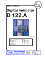
1
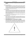
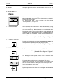
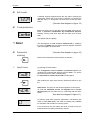
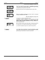
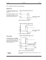
User's manual Digital Indicator D 122.A Software version 1.6 User’s manual for indicators D 122.A.0.0 D 122.A.0.2 D 122.A.3.0 D 122.A.3.2 D 122.A.5.0 D 122.A.5.2 D 122.A.6.0 D 122.A Contents Page 2 Table of contents 1 Operation instruction for Explosion protected control panels ................................................. 3 2 Digital Indicator D 122.A ................................................................................................................ 4 2.1 Short description ....................................................................................................................... 4 2.2 Option: Internal zener barrier .................................................................................................... 4 2.3 Features overview..................................................................................................................... 4 3 Installation and Connection .......................................................................................................... 5 3.1 Mounting Instructions ................................................................................................................ 5 3.2 3.2.1 Connecting ................................................................................................................................ 6 Connecting D122A with zener barrier option..................................................................... 8 3.3 Starting ...................................................................................................................................... 8 4 Operating manual........................................................................................................................... 9 4.1 Front view.................................................................................................................................. 9 4.2 Keyboard ................................................................................................................................... 9 4.3 Configuration............................................................................................................................. 9 4.4 Configuration example ............................................................................................................ 14 5 Option special software............................................................................................................... 17 6 Flow charts ................................................................................................................................... 18 7 Annex............................................................................................................................................. 24 7.1 Specifications .......................................................................................................................... 24 1.2 Type code ............................................................................................................................... 25 1.3 Wiring Examples ..................................................................................................................... 25 1.4 Dimensions ............................................................................................................................. 26 1.5 List of Parameters ................................................................................................................... 27 1.6 Index........................................................................................................................................ 29 Gönnheimer Elektronik GmbH Tel.: +49(6321) 49919-0, Fax: -41 [email protected] D 122.A 1 1 Operation intructions Page 3 Operation instruction for Explosion protected control panels Application and Standards This instruction manual applies to explosion protected control panels of type of protection types below. This apparatus is only to be used as defined and meets requirements of EN 60 079 particularly EN60 079-14 "electrical apparatus for potentiality explosive atmospheres". It can be used in hazardous locations which are hazardous due to gases and vapours according to the explosion group and temperature class as stipulated on the type label. When installing and operating the explosion protected distribution and control panels the respective nationally valid regulations and requirements are to be observed. General Instructions The control panel has to have a back-up fuse as stipulated. The mains connection must have a sufficient short circuit current to ensure safe breaking of the fuse. To achieve an impeccable and safety device operation, please take care for adept transportation, storage and mounting, as well as accurate service and maintenance. Operation of this device should only be implemented by authorised persons and in strict accordance with local safety standards. The electrical data on the type label and if applicable, the "special conditions" of the test certificate PTB 98 ATEX 1488 are to be observed. For outdoor installation it is recommended to protect the explosion protected distribution and control panel against direct climatic influence, e.g. with a protective roof. The maximum ambient temperature is 40°C, if not stipulated otherwise. Intrinsically Safe Circuits Erection instructions in the testing certificates of intrinsically safe apparatus are to be observed. The electrical safety values stipulated on the type label must not be exceeded in the intrinsically safe circuit. When interconnecting intrinsically safe circuits it is to be tested, whether a voltage and/or current addition occurs. The intrinsic safety of interconnected circuits is to be ensured. (EN 60079-14, section 12) Safety Measures: to read and to comply Work on electrical installations and apparatus in operation is generally forbidden in hazardous locations, with the exception of intrinsically safe circuits. In special cases work can be done on non-intrinsically safe circuits, on the condition that during the duration of such work no explosive atmosphere exists. Only explosion protected certified measuring instruments may be used to ensure that the apparatus is voltage-free. Grounding and short circuiting may only be carried out, if there is no explosion hazard at the grounding or short circuit connection. ! Gönnheimer Elektronik GmbH Tel.: +49(6321) 49919-0, Fax: -41 [email protected] D 122.A 1 Operation intructions 2 Digital Indicator D 122.A 2.1 Short description Page 4 The digital Indicator D122 indicates measured values of intrinsically safe current circuits from 4 up to 20 mA in hazardous areas. The device is powered by measure current, therefore an extra power supply or batteries are unnecessary. The indicator measures the current, scales the measured value and displays finally the result on the LCD. For trend analysis, the measured signal is also be displayed on a 41 segment bargraph. It's possible to scale the bargraph separately to the digital value. The indicator D122 is available in several housings. Furthermore with alarm monitoring option the indicator has two intrinsically safe alarm outputs. These outputs change their state, when the measured value exceeds his alarm limits. It’s possible to choose open-circuit or closed-circuit connection. Additional the alarm limits appear graphically on a second bargraph. On one look you’re sure that the measured value is in its limits. 2.2 Option: Internal zener barrier The standard digital indicator D122 works exclusively in intrinsically safe 4..20 mA current circuits (EEx i). If the concerned measure current circuit is not intrinsically safe, an extra zener barrier or an isolated interface and a long additional cable to the interface outside the hazardous area and back is needed. In those cases the option integrated zener barrier is very practical, because the interface is build in. A further advantage of an indicator with this option is that the intrinsical safety proof is not required. The ignition protection is EEx m [ib] IIC T6 at ambient temperature of 50°C, E Ex m [ib] IIC T4 at 65 °C respectively. The terminal voltage in the measure circuit with internal zener barrier option is about 2 V. 2.3 Features overview Basic functions • • • • • Loop-powered digital Indicator Connect like passive analogue indicators, voltage drop ca. 1V LC-Display up to 50 mm figure-height Scale by buttons and display Fast bargraph for trend observation (41 segments, refresh 4 times per second) • Separately scaleable Bargraph (Zoom) • Several housings available (control panel- and field housing) Options • Alarm monitoring: two intrinsically safe alarm outputs and an additional limitbargraph on the display • Limit-functions with hysteresis and time delay • Field housing with additional (2nd) PG-Connector Gönnheimer Elektronik GmbH Tel.: +49(6321) 49919-0, Fax: -41 [email protected] D 122.A 1 Operation intructions Page 5 Explosion protection ❏ In accordance with CENELEC specifications • EN 50014: 1997 • EN 50020: 1994 • EN 50028: 1988 ❏ explosion protection type • E Ex ib IIC T6 at ambient temperature up to 45°C or E Ex ib IIC T5 at ambient temperature up to 60°C • EEx m [ib] T6 with Option zener barrier 3 Installation and Connection 3.1 Mounting Instructions Control panel housing D 122.A.0 and D 122.A.3 The digital indicators D122.A.0 and D 122.A.3 are predicated for installation in a control panel. How to insert the dimension symbol Insert the dimension symbol (icon) before mounting. Do this by first removing the front frame as shown in the figure at left. Now remove the front panel from the housing as shown in the figure on the right. Cut the desired dimension-symbol from the set and pull it into its intended place on the right side of the panel. Make sure that the symbol is facing the front. Replace the front panel and frame. How to fix the device in the control panel Fix the indicator into the control panel with the intend cramps. Field housing D 122.A.5 and D 122.A.6 When mounting the housing box on a wall, be sure that it is securely supported by anchoring the screws into a stud or other solid surface. How to insert the Dimensionsymbol First, cut the desired dimension symbol out of the set. Then pull off the four screws of the cap and remove the cap from the housing. Now push the prepared dimension-symbol into the dimension-symbol-slot. Make sure that the symbol is facing the front. The dimension-symbol-slot lies below the display, on the internal side of the cap. Finally replace the cup on the housing. Gönnheimer Elektronik GmbH Tel.: +49(6321) 49919-0, Fax: -41 [email protected] D 122.A 3.2 3 Installation and Connection Page 6 Connecting Note Control panel housing Connect the indicator only to intrinsically safe 4 ... 20 mA current circuits. The terminals of the indicators in the control panel housing are shown in figure 1. The terminals 5,6 and 7,8 are absent by indicators without alarm monitoring. Intrinsically safe measure circuit 4 ..20 mA Terminals 1,2 Alarm monitoring option terminals 5,6 low alarm terminals 7,8 high alarm Figure 1: Terminals by indicators with control panel housing Note Be sure that the no-load voltage must be below 65 V and short-circuit current be below 160 mA for all types of indicators. Gönnheimer Elektronik GmbH Tel.: +49(6321) 49919-0, Fax: -41 [email protected] D 122.A Field – housing 3 Installation and Connection Page 7 The terminals of the indicators with field housing are inside. The placement of the terminals is shown at the following figures. Figure 2 shows the terminals of the indicator D 122.A.5. Figure 3 shows the terminals of the indicator d 122.A.6. The terminals 5,6 and 7,8 are absent by indicators without alarm monitoring. Figure 2: Terminals of the indicator D 122.A.5 Figure 3: Terminals of the indicator D 122.A.6 Gönnheimer Elektronik GmbH Tel.: +49(6321) 49919-0, Fax: -41 [email protected] D 122.A 3 Installation and Connection Page 8 3.2.1 Connecting D122A with zener barrier option Connect the D122.A.x.x.BM to a non intrinsically safe transmitter. Note Inside of hazardous area the D122A.x.x.BM cable must be connected in a certificated EEx e-connection box Figure 4: Connection of D122.A.x.x.BM 3.3 Starting Note Default parameters After connecting, a display test (all segments of the display are turned on) appears immediate during one second. Thereupon the display shows the software version of the indicator. The following parameters are active ex works: Scaling (display and bargraph) 4 mA curent -> 4.00 20 mA current -> 20.00 Note (RESET) Limits Low: 4.00 mA / High: 20.00 mA Hysteresis / Delay 0.10 / 0 sec. alarm outputs (alarm monitoring) circuit-opening connection Code words CODE1: 0001 / CODE2: 0002 Press the Enter- and Right-button during the start sequence to reactivate the default parameters. (Hardware-Reset) An reset activates also the ex works calibration. Gönnheimer Elektronik GmbH Tel.: +49(6321) 49919-0, Fax: -41 [email protected] D 122.A 4 Manual 4 Operating manual 4.1 Front view 4.2 Keyboard Page 9 On the front side of the indicator are tree buttons with several function symbols. With these tree buttons the user can activate each function and enter all parameters for any individual setting. Each button is named by its function: Enter-button Pressing the enter-button starts the input menu. In general, the enter-button activates the menu item or accepts the manipulated value of a parameter. Up-button Functions of the up-button are: 1. current control button 2. modification of the selected figure 3. pass menu items Right-button Functions of the right-button are: 1. change the display to limit view 2. select figures 3. pass menu items 4.3 Configuration It is easy to set the parameters and change the configuration of the indicator. The inputs are logically grouped by a menu structure. The flow diagram of these menus can be found in the appendix. Gönnheimer Elektronik GmbH Tel.: +49(6321) 49919-0, Fax: -41 [email protected] D 122.A 4 Manual Note Page 10 Indicators without the alarm monitoring option have not got the corresponding menu items. Note flow charts SET Normal state The Input views in the flow diagrams have additional boxes in their background, because the Input views may be changed by pressing any of the buttons. The procedure, to enter a value, is shown in the flow diagram ‘Value input menu’, see figure 12. After connecting, the indicator D122 starts to initialise its configuration. The configuration data is stored in an internal EEPROM due to the previous run. By the first start, the D122 indicator initialises the default configuration. Directly past starting sequence the indicator begins to display the measured current digital and analogous on the bargraph. This state is called the ‘normal state’ of the D122 and the indicator is also ready for inputs. (See also flow diagram in figure 8) current control Pressing and holding the up-button (current control button) the display shows the present current and the [mA] symbol. (See also flow diagram in figure 8) limit view menu (Only for indicators with the alarm monitoring option) One touch on the right-button starts the limit view menu. (See also flow diagram in figure 9) SET SET The display [limit low] appears on the screen. Press the enterbutton to watch the value of the lower limit. For passing the low limit press the right-button. The menu changes to the high limit. The screen shows now [limit high]. Confirm with the enter-button to display the value of the upper limit. Pressing the right-button for a second time quits the limit view menu and returns to normal state. During watching the limit values it is possible to manipulate them by pressing the enter-button. The view changes to the Gönnheimer Elektronik GmbH Tel.: +49(6321) 49919-0, Fax: -41 [email protected] D 122.A 4 Manual Page 11 Edit mode. A blinking segment appears below the sign place. Pressing the right-button selects the figure and the up-button increments the selected figure. To accept the new limit value, press the enterbutton. SET (See also flow diagram in figure 12) Code protection Max Before the menu gets to the edit mode the code 2 must be entered, to prevent a modification by unauthorised persons. Entering a wrong code word stops the limit view menu immediately. The default code 2 is [0002]. Note! Parameter entering The interrogation of code 2 can be switched off by modifying the code 2 to [0000]. For this reason the flow diagram shows the code interrogation in stroked dots. (See also flow diagram in figure 10) Back in the normal state of the indicator we start the Input menu by pressing the enter-button. The configuration of the indicator is protected against manipulations by unauthorised persons with the code 1. To get the input menu enter the code 1 default [0001]. It’s impossible to switch off the code 1 interrogation. After entering the right code word the indicator proposes to join the Scale menu. The figure on the left hand appears on the screen. To scale the measured current, the bargraph and to set the decimal point join the scale menu by confirming with the enterbutton. See also flow diagram in figure 11). To pass the scale menu press the right-button. The following sub menu is called limit menu. This menu is naturally only available for indicators with the alarm monitoring option. In the limit menu the user enters the limits, as well as the hysteresis and the time delay of the alarm outputs. Gönnheimer Elektronik GmbH Tel.: +49(6321) 49919-0, Fax: -41 [email protected] D 122.A 4 Manual Page 12 (See also flow diagram in figure 14) The next two following items allow to manipulate the words for code 1 and code 2. The enter-button confirms the input and the corresponding code appears in edit mode. Remember that the code word [0000] switches off the code 2. Max Finally it’s possible to calibrate the indicator with the following sub menu called calibration menu. (See flow diagram in figure 15) Note! The indicator is already calibrated ex-works. In general, a further calibration is not necessary and only experienced persons are allowed to calibrate it. Wrong calibration causes senseless Indications. To start calibration enter the code word 0123. Now we reach the end of the input menu. Confirm the end with the enter-button. The indicator switches back to normal state. If you want to repeat the input menu, press the right-button. Note! Gönnheimer Elektronik GmbH If an invalid value is entered for any of the parameters, you will not be able to quit the input menu. Instead, the program switches automatically into edit mode to the found valid value. Tel.: +49(6321) 49919-0, Fax: -41 [email protected] D 122.A 4 Manual Page 13 Hysteresis and time delay setting Hysteresis A hysteresis prevents an unwanted fast switching of the alarm outputs. alarm monitoring lower limit The switching behaviour of the low alarm (min) shows figure 5. The switching behaviour of the high alarm (max) shows figure 6. on off measured value lower limit Figure 5: Hysteresis low alarm alarm monitoring upper limit hysteresis at upper limit on off measured value upper limit Figure 6: Hysteresis high alarm alarm monitoring upper limit Time delay The span of time ‘te’ is the difference between the first exceeding of the measurement above the upper limit and the switching of the high alarm (For the low alarm exists an analogous ‘te’). time delay te on off time measured value upper limit time moment of first exceeding Figure 7: Time delay max respectively min Note Gönnheimer Elektronik GmbH If the measured current falls below the high limit during ‘te’, the tetimer resets. Tel.: +49(6321) 49919-0, Fax: -41 [email protected] D 122.A 4.4 4 Manual Page 14 Configuration example See the following example of a temperature measurement for a successful parameter input. ❏ Situation • desired range: +10°C ... 20°C • sensor range: -20.0°C ... +30.0°C ❏ Adjustment 1] Measure range: -20,00 °C ... + 30,00°C for 4 ... 20 mA 2] Bargraph: -5°C ... + 25°C 3] Limits: lower limit (min): +10°C upper limit (max.): +20°C 4] Hysteresis: 0,5°C low and high limit 5] Alarm monitoring mode: circuit-opening connection 6] Time delay: 15 seconds Procedure: One touch on the enter-button quits the normal state and starts the input menu. The menu interrogates for code 1. The default code 1 is [0001]. Enter the right code word using the arrow buttons. Finally hit the enter-button. Scaling display and bargraph: Join the scale menu pressing the enter-button. SET First set the position of the decimal point. The position of the decimal point will be used for each parameter, like display, bargraph and limits. Set the decimal point position after the second position, because we will enter [2000] for the high scale point afterwards. Fortunately the default setting is on the desired position, so we can pass the item pressing the right-button. Gönnheimer Elektronik GmbH Tel.: +49(6321) 49919-0, Fax: -41 [email protected] D 122.A 4 Manual SET SET SET Page 15 Now the [scale point low] view appears. Confirm by pressing the enter-button and enter the lower scale point (-20°C) as follows: Choose the negative sign pressing the up-button. Touch the right-button to select the first figure. Now hit the up-button two times ... SET ... and the figure ‘2’ will be adjusted. SET Press the right-button to select the next figure. SET Hit the up-button until the figure ‘0’ appears. SET Confirm the lower scale point pressing the enter-button. Now the... ... item appears. Repeat the input procedure for the upper scale point like the lower scale point. Enter [3000] for the upper scale point. (Confirm by hitting enter-button) Hint! SET SET Enter the upper scale point correct figured ‘as big as possible’ (the first figures should not be ‘0’) In this case you get most precision of the indicator. Now scale the bargraph. Hit the enter-button. Enter [-0500] (-5°C) for the lower bargraph scale point. Confirm by hitting the enter-button Enter [2500] (25°C) for the upper bargraph scale point. Hitting enter-button accepts and quits the scale menu. Limits, Hysteresis and time delay Start limit menu by pressing the enter-button. Gönnheimer Elektronik GmbH Tel.: +49(6321) 49919-0, Fax: -41 [email protected] D 122.A 4 Manual SET SET SET SET SET SET SET SET Page 16 Press the enter-button for a second time and enter [1000] (10°C) for the lower limit using the arrow buttons. Confirm by hitting the enter-button. (Remember, that the decimal point position is already set) Press the enter-button and enter [2000] (20°C) for the upper limit. Confirm by hitting the enter-button. To select the hysteresis of the lower limit press the enterbutton. Now enter [0050] (0,5°C) using the arrow-buttons and confirm with the enter-button. To select the hysteresis of the upper limit press the enterbutton. Now enter [0050] (0,5°C) using the arrow-buttons and confirm with the enter-button. Now press enter-button to activate the time delay. Enter [0015] (15 seconds) for both limits. Confirm by hitting the enter-button. Now define the circuit-opening connection first for the low alarm limit. Choose the circuit-opening connection [nc---] (normal closed) using the up-button and confirm by pressing enter-button. Define the circuit-opening connection for the upper alarm monitor by the same procedure. Confirm by hitting the enter-button and quit the limit menu. We pass simply the following menu items (manipulate code words and calibrate) using the right-button. Finally quit the scale menu hitting the enter-button. The indicator is back in normal state. The changes are immediately active and will be stored after turn off (disconnecting the indicator). Gönnheimer Elektronik GmbH Tel.: +49(6321) 49919-0, Fax: -41 [email protected] D 122.A 5 5 Special software Page 17 Option special software The indicator D122.AS as well as the totalizer D122.ZS have a special software option. With this option it is possible to use this devices in any individual cases of measurement and indication. Curve fitting The curve fitting software indicates the measure current in a non-linear way. Consider the application of a filling-level meter for a sphere-tank. The measure current is linear to the filling-height of the liquid. But the function between the filling-height and the volume is non-linear, as shown in the figure below. To get the correct quantity indication you require a list of points, which shows the connection between measure current and associated quantity inside of the tank. The curve fitting software of the D122.XS interpolates the curve between these points on your choice in a linear or a square way. The linear interpolation generates imaginary straight lines between the selected points. A value on this line will be calculated on base of his distance to the previous selected point. This kind of interpolation requires 17 points to scale 4 up to 20 mA. On the other hand the square interpolation needs a list of 33 points, but it approximates the original curve much better than the linear one, so the error between the original curve and the interpolated curve is much smaller. To put in the list of selected point enter the (extended) scale menu. The device displays the measure current and you have to enter the associated display value. See also flow diagram in Figure 13. Squareroot-fitting To program a squareroot-function, e.g., to display the flow through a aperture, a special squarerootfitting feature is available. For this option it is not necessary to enter a list of points, but just a startand a end-value (in previous example: associated flow by 4 and by 20mA measure current). The device calculates automatically the selected points for interpolation. Be prepared, this procedure will take some time. See also flow diagram in Figure 13. Gönnheimer Elektronik GmbH Tel.: +49(6321) 49919-0, Fax: -41 [email protected] D 122.A 6 6 Flow charts Page 18 Flow charts D 122.A START Limit view menu Min Max Input menu Normal state mA Min Max Current control view Figure 8: Flow diagram normal state Figure 9 Flow diagram limit view Gönnheimer Elektronik GmbH Tel.: +49(6321) 49919-0, Fax: -41 [email protected] D 122.A Input menu START 6 Flow charts Interrogate code 1 Page 19 false code word Ok SET Scale menu select scale menu SET Limit menu select limit menu SET select code 1 modify code 1 SET modify code 2 select code 2 SET Calibration menu select calibration menu quit input menu Yes Input menu END No Figure 10: Flow diagram input menu Gönnheimer Elektronik GmbH Tel.: +49(6321) 49919-0, Fax: -41 [email protected] Scale menu END edit bargraph high position SET select bargraph high position select bargraph low position SET SET edit bargraph low position Page 20 SET edit high cale point (20 mA measure cur.) select high scale point SET SET select low scale point SET SET edit low scale point (4 mA measure cur.) 6 Flow charts Scale menu START SET select decimal point position SET set position D 122.A Figure 11: Flow diagram scale menu edit values enter code SET SET SET sign is selected Menu END SET Menu END Menu END Menu END Menu END SET SET etc. first figure is modified sign is modified etc. second figure is modified first figure is modified SET Menu END SET SET sign is modified etc. second figure is selected first figure is selected Menu END etc. second figure is modified Menu END etc. Menu END etc. Figure 12: Flow diagram edit mode Gönnheimer Elektronik GmbH Tel.: +49(6321) 49919-0, Fax: -41 [email protected] D 122.A 6 Flow charts Page 21 Alternative (extended) scale menu for special software option only Figure 13: Flow diagram extended scale menu Gönnheimer Elektronik GmbH Tel.: +49(6321) 49919-0, Fax: -41 [email protected] D 122.A 6 Flow charts Page 22 Figure 14: Flow diagram limit menu Gönnheimer Elektronik GmbH Tel.: +49(6321) 49919-0, Fax: -41 [email protected] D 122.A 6 Flow charts Calibration menu START Interrogate code Page 23 false code word Ok SET calibration pass 1 SET 4 mA order 4 mA input current SET calibration pass 2 SET 20 mA order 20 mA input current SET calibration pass 3 Calibration menu END Figure 15: Flow diagram calibration menu Gönnheimer Elektronik GmbH Tel.: +49(6321) 49919-0, Fax: -41 [email protected] D 122.A 6 Flow charts 7 Annex 7.1 Specifications Page 24 D 122 D 122.A.0 Display Digit height 15mm 30mm D 122.A.6 3½-digits 30mm 50mm -19999 ... +19999 Dimension symbols -1999 ... +1999 Selectable with defined symbols Decimal points Selectable by keyboard Bargraph 41 segments Alarm limits display Alarm limit monitoring D 122.A.5 4½ -digit seven-segment LCD Display range Versions D122.A. .2 D 122.A.3 / - Via bargraph - Flashing ‘max.’ or ‘min’ display By means of intrinsically safe control circuits (e.g. NAMUR or DIN 19234) Version D122.A. .2 Current control button Direct display of current in measurement circuit Measurement circuit Intrinsically safe measurement circuit 4 ...20 mA; Voltage drop ca. 1V Measurement circuit limits No-load Voltage Ui ≤ 65 V; short-circuit current Ik ≤ 160 mA Internal inductance: ≤ 40 µH; Internal capacitance: ≤ 10 nF, see certificate TÜV 99 ATEX 1488 Limits with zener barrier option UM = 250 V see certificate TÜV 99 ATEX 1488 Alarm monitoring limits By intrinsically safe control circuits No-load Voltage Ui ≤ 30 V; Short-circuit current Ii ≤ 160 mA Pmax not greater than 850 mW; Internal inductance: ≤ 40 µH Internal capacitance is negligible, see certificate TÜV 99 ATEX 1488 Explosion protection E Ex ib IIC T6 at ambient temperature 45°C or E Ex ib IIC T5 at ambient temperature 60°C Housing Protection class Acc. to control-panel standard DIN 43700 Front panel IP 40 up to IP 65 Dimensions HxWxD [mm] 48x96x62 Material glass fibre strengthened Noryl Measuring error Temperature - 72x144x80 IP 65 134x138x64 138x184x64 ABS 0,1% ± 2 digits referring to measure range < 0,01% of measure range / K coefficient Ambient temperature limit -10°C ...+45°C for temperature class 6 or -10°C ...+60°C for temperature class 5 Indicators for -20°C ambient temperature on inquiry D 122.A 7.2 6 Flow charts Page 25 Type code Device series D122 . . . Device: Indicator ................................................................ .A Indicator with curve fitting option ............................. .AS Totalizer .................................................................. .Z Totalizer with curve fitting option ............................. .ZS Housing: Control panel housing 48 x 96 mm ....................... .0 Control panel housing 72 x 144 mm .................... .3 Field housing (30 mm Ziffernhöhe) ........................ .5 Field housing (50 mm Ziffernhöhe) ......................... .6 Digital output: without ................................................................. .0 with 2 digital outputs ............................................ .2 with reset input and pulse output ......................... .3 Additional option: Internal zener barrier .BM ............................................................... 7.3 Wiring Examples Figure 16: Monitoring of alarm limits D 122.A 7.4 Dimensions Figure 17: Control panel housing cut-out Figure 18: Field housing cut-out 6 Flow charts Page 26 D 122.A 7.5 6 Flow charts Page 27 List of Parameters The customer is free to use this chart for archiving the parameters of his indicator D122. Parameter Description Previous Display Value Scale menu Decimalpoint position dP.PoS Low scale point Display at 4 mA input current SCAL L High scale point Display at 20 mA input current SCAL H Bargraph low position Display at starting bargraph bAr L Bargraph high position Display at full bargraph bAr H 0000 Limit menu Low limit LI L High limit LI H Hysteresis of low limit HYS L Hysteresis of high limit HYS H Alarm connection of low limit Choice between normal open (no) and normal closed (nc) Con L nc no Alarm connection of high limit Choice between normal open (no) and normal closed (nc) Con H nc no Code word Nr. 1 CodE 1 Code word Nr. 2 CodE 2 Only on Option Sondersoftware Low scale point root function Display at 4 mA input current roo L High scale point root function Display at 20 mA input current roo H D 122.A linear or square Interpolation Setpoint 6 Flow charts Choice between linear or square Interpolation Page 28 INTER 400 450 500 550 600 650 700 750 800 850 900 950 1000 1050 1100 1150 1200 1250 1300 1350 1400 1450 1500 1550 1600 1650 1700 1800 1850 1900 1950 2000 In 33 In17 D 122.A 7.6 6 Flow charts Index A H alarm limit monitoring 24 hardware-reset 8 hysteresis 4, 8, 11, 13, 14 C closed-circuit connection 4, 14 code protection 11 configuration 9 configuration example 14 control panel housing 5 current control 10 current control button 9 D decimal point 14 dimension symbol 5 E ex works 8 L limit high 10 limit view menu 10 lower scale point 15 N NAMUR 24 Noryl 24 P parameter entering 11 precision 15 T temperature 24 time delay 13 Page 29 (&7<3((;$0,1$7,21&(57,),&$7( 7UDQVODWLRQ (TXLSPHQWDQGSURWHFWLYHV\VWHPVLQWHQGHGIRUXVHLQ SRWHQWLDOH[SORVLYH$WPRVSKHUHV¤'LUHFWLYH(& (&W\SHH[DPLQDWLRQ&HUWLILFDWHQXPEHU 7h9$7(; (TXLSPHQW 'LJLWDO,QGLFDWRU7\SH' $GGUHVV '1HXVWDGWDQGHU:HLQVWUDH 0DQXIDFWXUHU *|QQKHLPHU(OHNWURQLF*PE+ 7KLVHTXLSPHQWDQGDQ\DFFHSWDEOHYDULDWLRQWKHUHWRDUHVSHFLILHGLQWKHVFKHGXOHWR WKLVFHUWLILFDWHDQGWKHGRFXPHQWVWKHUHLQUHIHUUHGWR 7KH 7h9 +DQQRYHU6DFKHQ$QKDOW H9 7h9 &(57=HUWLIL]LHUXQJVVWHOOH QRWLILHG ERG\1RLQDFFRUGDQFHZLWK$UWLFOHRIWKH&RXQFLO'LUHFWLYH(&RI0DUFK FHUWLILHVWKDWHTXLSPHQWKDVEHHQIRXQGWRFRPSO\ZLWKWKH(VVHQWLDO+HDOWKDQG 6DIHW\ 5HTXLUHPHQWV UHODWLQJ WR WKH GHVLJQ DQG FRQVWUXFWLRQ RI HTXLSPHQW DQG SURWHFWLYHV\VWHPVLQWHQGHGIRUXVHSRWHQWLDOO\H[SORVLYHDWPRVSKHUHVJLYHQLQ$QQH[ ,,WRWKH'LUHFWLYH 7KH H[DPLQDWLRQ DQG WHVW UHVXOWV DUH UHFRUGHG LQ WKH FRQILGHQWLDO UHSRUW 1R 3; &RPSOLDQFH ZLWK WR HVVHQWLDO +HDOWK DQG 6DIHW\ 5HTXLUHPHQWV KDV EHHQ DVVXUHG E\ FRPSOLDQFHZLWK (1 (1 (1 ,IWKHVLJQ¦;§LVSODFHVDIWHUWKHFHUWLILFDWHQXPEHULWLQGLFDWHVWKDWWKHHTXLSPHQWLV VXEMHFWWRVSHFLDOFRQGLWLRQVIRUVDIHXVHVSHFLILHGLQWKHVFKHGXOHWRWKLVFHUWLILFDWH 7KLV(&W\SH H[DPLQDWLRQ&HUWLILFDWH UHODWHVRQO\WRWKH GHVLJQ DQG FRQVWUXFWLRQ RI WKH VSHFLILHG HTXLSPHQW LQ DFFRUGDQFH ZLWK 'LUHFWLYH (& )XUWKHU UHTXLUHPHQWV RIWKLV'LUHFWLYHDSSO\WRWKHPDQXIDFWXUHDQGVXSSO\RIWKLVHTXLSPHQW 7KHPDUNLQJRIWKHHTXLSPHQWVKDOOLQFOXGHWKHIROORZLQJ ,,*(([LD,,&7E]Z(([P>LE@,,&7 7h9+DQQRYHU6DFKHQ$QKDOWH9 7h9&(57=HUWLIL]LHUXQJVWHOOH $P7h9 '+DQQRYHU +DQQRYHU 'HU/HLWHU (&W\SHH[DPLQDWLRQ&HUWLILFDWHVZLWKRXWVLJQDWXUHDQGRIILFLDOVWDPSVKDOOQRWEHYDOLG7KHFHUWLILFDWHVPD\EHFLUFXODWHGRQO\ ZLWKRXWDOWHUDWLRQ([WUDFWVRUDOWHUDWLRQVDUHVXEMHFWWRDSSURYDOE\WKH7h9+DQQRYHU6DFKVHQ$QKDOWH9 3DJH RI 6&+('8/( (&7<3(([DPLQDWLRQ&(57,),&$7(1R7h9$7(; 'HVFULSWLRQRIHTXLSPHQW 7KH GLJLWDO LQGLFDWRU W\SH ' VHUYHV DV GLUHFW LQGLFDWRU RI PHDVXUHG YDOXHV RI LQWULQVLFDOO\VDIHP$FXUUHQWFLUFXLWVLQH[SORVLYHHQGDQJHUHGDUHDV 7KHPD[LPXPDPELHQWWHPSHUDWXUHLV&LQWHPSHUDWXUHFODVV7DQG&LQWKH WHPSHUDWXUHFODVV7 (OHFWULFDOGHWDLOV 6XSSO\DQG VLJQDOFXUUHQW FLUFXLW 7HUPLQDO 2QO\7\SH'7[[[ 6XSSO\DQG VLJQDOFXUUHQW FLUFXLW 7HUPLQDO 7HUPLQDOV ([FOXVLYH FRQQHFWLRQ WR D FHUWLILFDWHG LQWULQVLFDOO\ VDIH FXUUHQWFLUFXLWZLWKWKHIROORZLQJKLJKHVWYDOXHV 8L 9 ,L P$ (IIHFWLYHLQWHUQDOLQGXFWLYLW\ + (IIHFWLYHLQWHUQDOFDSDFLW\ Q) ([FOXVLYH FRQQHFWLRQ WR D FHUWLILFDWHG LQWULQVLFDOO\ VDIH FXUUHQWFLUFXLWZLWKWKHIROORZLQJKLJKHVWYDOXHV 8L 9 ,L P$ 3L : (IIHFWLYHLQWHUQDOLQGXFWLYLW\ + HIIHFWLYHLQWHUQDOFDSDFLW\ Q) %ULGJHW 2QO\ 7<3 [[[%0 ZLWK DGGLWLRQDO SURWHFWLRQ W\SH PRXOGLQJ DQG WKH VLJQ(([ P >LE@,,&7E]Z(([P>LE@,,&7 ,QSXWFXUUHQW FLUFXLWZLUH 8P 9DQGWRFRQQHFWWRJURXQG (&W\SHH[DPLQDWLRQ&HUWLILFDWHVZLWKRXWVLJQDWXUHDQGRIILFLDOVWDPSVKDOOQRWEHYDOLG7KHFHUWLILFDWHVPD\EHFLUFXODWHGRQO\ ZLWKRXWDOWHUDWLRQ([WUDFWVRUDOWHUDWLRQVDUHVXEMHFWWRDSSURYDOE\WKH7h9+DQQRYHU6DFKVHQ$QKDOWH9 3DJH RI 6FKHGXOH(&7\SH([DPLQDWLRQ&HUWLILFDWH1R7h9$7(; $Q\W\SHV $ODUPFXUUHQW FLUFXLWV 7HUPLQDO 2XWSXWV ,QSXWV ([FOXVLYH FRQQHFWLRQ WR D FHUWLILFDWHG LQWULQVLFDOO\ FXUUHQW FLUFXLWZLWKWKHIROORZLQJKLJKHVWYDOXHVHDFKFXUUHQWFLUFXLW 8L ,L 3L 8L 9 P$ P: 9 (IIHFWLYHLQWHUQDOLQGXFWLYLW\d + WKHHIIHFWLYHLQWHUQDOFDSDFLW\LVQHJOLJLEO\VPDOO $OOFXUUHQWFLUFXLWVDUHVDIHJDYDQLFDOO\VHSDUDWHGXSWRDQRPLQDOYROWDJHRI9WR HDFKRWKHU7KHLQSXWFXUUHQWFLUFXLWE\WKHW\SH'[[[%0LVLQWHUQDOO\FRQQHFWHG WRWKHVXSSO\DQGVLJQDOFLUFXLW 5HSRUW1R3; 6SHFLDOFRQGLWLRQVIRUVDIHDUHD (VVHQWLDOKHDOWKDQGVDIHW\UHTXLUHPHQWV 1RQH 1RDGGLWLRQDO (&W\SHH[DPLQDWLRQ&HUWLILFDWHVZLWKRXWVLJQDWXUHDQGRIILFLDOVWDPSVKDOOQRWEHYDOLG7KHFHUWLILFDWHVPD\EHFLUFXODWHGRQO\ ZLWKRXWDOWHUDWLRQ([WUDFWVRUDOWHUDWLRQVDUHVXEMHFWWRDSSURYDOE\WKH7h9+DQQRYHU6DFKVHQ$QKDOWH9 3DJH RI EG-Konformitätserklärung Declaration of conformity / Déclaration de conformité Communauté Européenne Anbieter: Supplier: Fournisseur: Gönnheimer Elektronic GmbH Anschrift: Address: Adresse: Gewerbegebiet Nachtweide Dr.-Julius-Leber-Straße 2 67433 Neustadt/Weinstraße Produkt: Product: Produit: D122.X.7.X.X, Anzeigegerät / Zähler Das oben beschriebene Produkt erfüllt die Schutzanforderungen der folgenden EG-Richtlinien / the product described above complies with the following EG- rules / le produit décrit cidessus accomplit CU- réglementations 89/336/EWG, 93/68/EWG, 94/9/EG und ist konform mit / and is in conformity with / et est conforme á: EN 50014: 1997, Allgemeine Bestimmungen EN 50020: 2002, Eigensicherheit „i“ EN 50028: 1988, Vergusskapselung „m“ EN 50281-1-1:1998, „Staub Ex“ DIN EN 60079-27: „FISCO“ EN 61000-6-3: Fachgrundnorm Störaussendung; Teil 6-3: Wohnbereich, Geschäfts- und Gewerbebereiche sowie Kleinbetriebe EN 61000-6-2: Fachgrundnorm Störfestigkeit; Teil 6-2: Industriebereich DIN VDE 0106-100:1983, Schutz gegen elektrischen Schlag zusätzliche Angaben / additional information / informations supplémentaires: Qualitätsmanagement- System nach ISO EN DIN 9001 Anerkanntes Qualitätssicherungssystem nach Richtlinie 94/9/EG EG- Baumusterprüfbescheinigung / EC- Type certification / Attestation d’examen ce de type TÜV 99 ATEX 1488 Gönnheimer Elektronic GmbH rev.1 CE-Konformitätserklärung_serie_sertig.doc