1
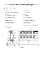
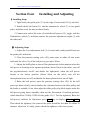
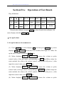
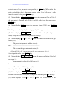
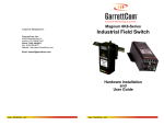
GBPM-10 Gas Meter Error Test Bench
(20L Bell Prover &Test Bench)
(For Gas Meter Qmin Error calibration)
User Manual
-1-
Contents
Section One
Outline…………………………………..……………(1)
Section Two
Working Principle………………..……………………(3)
Section Three
Main Technical Data…………..……...………………(5)
Section Four
Installation and Adjustment………………….………(6)
Section Five
Operation of Test Bench………………………………(8)
Section Six
Coefficient Calibration………………………………(15)
Section Seven
Test Method of Gas Meter…………….……………(16)
Section Eight
Service…………………………………...……....…(34)
Section Nine
Notice…………………………………...……....…..(38)
-2-
Section One
Outline
GBPM-10 Gas Meter Error Test Bench is especially in use for testing gas
meter Qmin error, and widely applied to the gas meter produce factory, gas
company and technical supervision department.
The facilities have many advantages as follows:
1.It adopts ten gas meter to test at a time, in order to improve the test
efficiency.
2.It adopts directional control valve to switch the airflow from right to left or
left to right.
3.It adopts bar code scanner to scan the gas meter ex-factory serial number
automatically.
4.It carries out the functions such as the automatic rise and fall of bell prover,
the automatic switch on-off of air valve, the automatic leak hunting of the system
before the test, the automatic switch on–off of flow point valve and so on, in order
to relieve the work intensity and improve the test efficiency.
-3-
Flow Measurement and Calibration
Section Two
Working Principle
Ⅰ. Shape Diagram (Figure 1)
1. Level Adjustment Bolt
13. Leader
2. Blower
14. Idler Pulley
3. Pressure Adjustment Weight
15. Bell Prover
4. Twine
16. Ruler
5. Compensative Weight
17. Magnifier
6. Compensative Wheel
18. Air Inlet Valve
7. Transmissive Wheel
19. Air Outlet Valve
8. Bearing Base
20. Pressure Testing Valve
9. Transmissive Gear
21. Water Tank
10. Rotary Encode
22. Liquid Outlet Valve
11. Beam
23. Ten position Qmin Test Bench
12. Guide Pole
3
2
0
1
9
8
7
1 23
1
11
6
8
6 1
71
5 1
4 1
1
5
4
3
9
1
2
1
0 2
2
2
2
1
(Figure 1)
4
Flow Measurement and Calibration
Ⅱ. Working principle
This Model LJQ bell prover standard facilities are composed of bell prover
system and ten-positions Qmin test bench. The effective volume of the bell
prover is used as the standard volume for calibrator, when the bell prover falls,
the air within flow from the bell prove and through the link pipeline and tested
meter to atmosphere. While the bell prover falling, the rotary encode that
connects with the gear translates the volume of the bell prover into the pulse
signal, and then the control system of the test-positions Qmin test bench turns the
pulse signal into the volume of the bell prover. Consequently the essential error
of the gas meter can be obtained by comparing the bell prover volume with the
gas meter indicative volume.
-5-
Flow Measurement and Calibration
Section Three
Main Technical Data
1. Sealed liquid: Clear water or white oil.
2. Standard volume: 5 L, 10 L, 20 L, 50 L, 100 L, 200 L, 500 L, 1000 L, 2000 L.
3. Accuracy: ±0.2%,±0.5%.
4. Working pressure: 1Kpa(Adjustable).
5. Working pressure fluctuation: ≤20Pa, ≤50Pa.
6. Working power: 220VAC,50Hz.
7. Shape size of the bell prover:
Length×Width×Height
Weight(Filling up with water)
(mm)
(Kg)
LJQ-20
LJQ-50
LJQ-100
LJQ-200
LJQ-500
LJQ-1000
550×400×1700
800×700×2300
1200×750×2950
1500×900×2950
1800×1250×2950
2000×1600×4500
70
250
500
1000
2000
3500
LJQ-2000
2500×2000×5800
7000
Model and Norms
8. Shape size of the test bench ( Length×Width×Height):2007×700×1875(mm) .
-6-
Flow Measurement and Calibration
Section Four
Installing and Adjusting
Ⅰ.Installing Steps
1. Tight firmly the guide pole (13) to the edge of water tank (21) by the bolt.
2. Install wholly the beam (11) and the transmissive wheel (7) to two guide
poles, and then screw the nuts on them firmly.
3. Connect one end of the twine (4) with the bell prover (15), joggle with the
Transmissive wheel(7), and then connect the pressure adjustment weight (3) with
the other end.
Ⅱ. Adjusting Steps
1. Adjust the level adjustment bolt (1) of water tank, make parallel between
the guide pole and twine.
2. Close the pressure testing valve (20), pour water or white oil into water
tank until the ruler (16) of the bell prover goes up to 20cm.
3. Adjust the baffle-plate to turn off the photoswitch to the moment when the
bell prover is locating at the topmost position (About 20cm on the ruler), turn off
the up-photoelectric on-off, and darkle the light-panel, when the bell prover
locates at the lowest position (About 98cm on the ruler), turn off the
down-photoelectric on-off, and darkle the down-photoelectric on-off light.
4. Raise the bell prover, open the pressure testing valve (20), let the bell
prover go down slowly, check whether the clearance between the idler pulley and
the leader is suitable, if not, then adjust the idler pulley slip block again, make the
bell prover going down smoothly, then test the fluctuation of working pressure,
which should be≤50Pa(≤20Pa for the grade 0.2).5. Test the tightness: Raise the
bell prover, stabilize for 10minutes, press 9/cal key to display nHb—A 00000.
Then check the tightness, the count of the pulse should be less than 20 within 30
minutes, otherwise it’s leaky, please check the tightness of the test system.
-7-
Flow Measurement and Calibration
Section Five
Operation of Test Bench
Key definition:
2/ns
5/δ
8
1/Q
4/δp,F
7
0/Test
3/δ1
6/△,K
Par Set
NO.Set
Hand A
Hand B
·
Qmax
0.2Qmax
Qmin
9/Cal
Air In
Air Out
Stop
Reset
Static/Clean
Dis/Ent
Electrify the calibrater or press Reset key after electrify the calibrater, the
meter displays initially gAS- - tESt.
Ⅰ. Set up the data
1. Set up the data not in common use
(1) Press Par Set key, meter displays SEt, and then press Dis/Ent key, meter
displays N-nO. ××××, means the tester number(Four digits are valid). Set
up the tester number and press Dis/Ent key.
(2) Meter displays CtL1—U ××××× , means the volume or pulse
control value of the gas meter corresponding to Qmax key(When adopt the
static method, the value is the volume control value of the bell prover ), after
input the control value, press Dis/Ent key.
(3) Meter displays CtL2—U ××××× , means the volume or pulse
control value of the gas meter corresponding to 0.2Qmax key(When adopt the
static method, the value is the volume control value of the bell prover ), after
input the control value, press Dis/Ent key.
(4) Meter displays CtL3—U ××××× , means the volume or pulse
-8-
Flow Measurement and Calibration
control value of the gas meter corresponding to Qmin key(When adopt the
static method, the value is the volume control value of the bell prover ), after
input the control value, press Dis/Ent key.
(5) Meter displays qH— ××××× ,means the maximum flow (m3/ h) of
the gas meter ( Generally qH=2.5,4, 6 and 10), after input the value, press
Dis/Ent key.
(6) Meter displays PASS-, means the password, input 12345, press Dis/Ent
key.
* Use this password to login before setting up the following contents.
(7) Meter displays tAbLE nO.××, means the table number (Two digits are
valid). Set up the table number and press Dis/Ent key.
(8) Meter displays bb— ×××××, means the meter coefficient of the gas
meter( n/ L)
The pulse that gas meter walks a turn (n)
bb =
——————————————————
The volume that gas meter walks a turn (L)
(Generally, bb =0.1, if used to count the gas meter pulse, bb=1)
After input the value, press Dis/Ent key.
(9) Meter displays bc— ×××××, means the meter coefficient of the bell
prover( n/ L)
The accumulative pulse of the bell prover (n)
bc = ————————————————————
The volume of the bell prover (L)
After input the value, press Dis/Ent key.
(10) Meter displays d10PA ××××× means the revised error of the
channel A for the Qmax flow point(%),input the value and press Dis/Ent key.
(11) Meter displays d10Pb ××××× means the revised error of the
-9-
Flow Measurement and Calibration
channel
B for the Qmax flow point(%), after input the value , press Dis/Ent
key.
(12) Meter displays d02PA ××××× means the revised error of the
channel A for the 0.2Qmax flow point(%), after input the value , press Dis/Ent
key.
(13) Meter displays d02Pb ××××× means the revised error of the
channel
B for the 0.2Qmax flow point(%), after input the value , press
Dis/Ent key.
(14) Meter displays t1 × × × × ×
means the start-up delay time
corresponding to Qmax flow point key.
(15) Meter displays t2 × × × × × means the start-up delay time
corresponding to 0.2Qmax flow point key.
(16) Meter displays t3 × × × × ×
means the start-up delay time
corresponding to Qmin flow point key.
(17) Meter displays Cq-t1 ××××× means the air pressure balance time
of the system before leak hunting.
(18) Meter displays Cq-t2 ××××× means the leak hunting time of the
system.
(19) Meter displays good means the data not in common use has been set up
completely.
2. Set up the meter number
×××××
nA
(1) Press No.Set key, meter displays
×××××
×××
,
means the ex-factory serial number of the gas meter tested in channel A (At
most ten digits), it can be scanned from the bar code by scanner, or input it by
the keyboard.
- 10 -
Flow Measurement and Calibration
(2) Meter displays ×××××
serial
nb
×××××
×××
, means the ex-factory
number of the gas meter tested in channel B (At most ten digits), it can be
scanned from the bar code by scanner, or input it by the keyboard.
Ⅱ. Display again
In order to check the set up data whether right or not, press Dis/Ent key,
display again the data that already set up.
Ⅲ. Display the tested value
1. Press 0/ Test key, display the volume of the bell prover and the tested meter at
the same time.
2. Press 1/ Q key, display circularly
q
××××× — means the moment flow ( m3/ h)
qb
××××× — means the average moment flow ( m3/ h)
Con-q
1.0-qH
— means the tested flow point is Qmax
Con-q
0.2-qH
— means the tested flow point is 0.2Qmax
Con-q
1-qL
— means the tested flow point is Qmin
3. Press 2/ ns key, display circularly
nHb—A ××××× — means the accumulative pulse of the bell prover
in channel A
nHb—B ××××× — means the accumulative pulse of the bell prover
in channel B
4. Press 3/δ1 key, display
- 11 -
Flow Measurement and Calibration
××××× — means the essential error of the gas meter before revised (%)
×××
— H — means the Qmax flow point
n — means the 0.2Qmax flow point
L — means the Qmin flow point
5. Press 4/δp, F , display circularly
d10PA ××××× — means the revised error of Qmax flow point in
channel A(%)
d10Pb ××××× — means the revised error of Qmax flow point in
channel B(%)
d02PA ××××× — means the revised error of 0.2Qmax flow point in
channel A(%)
d02Pb ××××× — means the revised error of 0.2Qmax flow point in
channel B(%)
F
××××× — means the output frequency of the coder
*δp — set up manually
6. Press 5/δkey, display
×××××
— means the essential error of the gas meter after revised (%)
×××
— H — means the Qmax flow point
n — means the 0.2Qmax flow point
L — means the Qmin flow point
*δ = δ1-δp
7. Press 6/Δ, K key, display circularly
×××××
- 12 -
Flow Measurement and Calibration
CFA
— means the repeatability error of the tested flow point in
channel A (%)
×××××
CFB
— means the repeatability error of the tested flow point in
channel B (%)
×××××
AC
— means the meter coefficient of the gas meter in channel A
×××××
BC
— means the meter coefficient of the gas meter in channel B
NOTE: The calculation of the repeatability error is selected by the two latest
tested values under the same flow point.
Ⅳ. Stop
Press Stop key, stop all actions.
Ⅴ. Clean
While setting up the data, if the input data have mistakes, press the
Static/Clean key, clean the input data, and input the right data again.
- 13 -
Flow Measurement and Calibration
Section Six Coefficient Calibration
Press 9/Cal
key, meter displays nHb-A ×××××, the calibtater opens
the testing pressure valve of the bell prover, starts to count, and takes the
accumulative pulse that corresponding to the volume of the bell prover. Calculate
the coefficient of the bell prover according to the meter coefficient calculation
formula.
The accumulative pulse of the bell prover (n)
bc = ————————————————————
The volume of the bell prover (L)
Section Seven
Test Method of Gas Meter
Test Manually (Static Method)
1.Read the initial value of the gas meter.
2.Press Static/Clean key, meter displays 0 0 0 0 0
××× —H—
means the Qmax flow point
n— means the 0.2Qmax flow point
L— means the Qmin flow point
then press relative flow point key, the calibrater starts to measure the volume of
the bell prover. When the bell prover reaches the control value, the calibrater
closes the air out valve automatically.
- 14 -
Flow Measurement and Calibration
Section Eight
Service
Diagnosis of and shooting at common troubles in bell prover
Phenomenon One︰The Bell Prover is vibrating, making some metallic friction
sound or blocked When the Bell Prover up and down.
Solution :
Step 1 : Check the clearance between the guide pole and Idler pulley, if too
tight ,adjust it to suitable.
Step 2 : Raise the Bell Prover to the top, observe the compensation rope and
Bell Prover are whether in one parallel lines or not, if not, adjust the level
adjustment bolts at the bottom of the Bell Prover.
Phenomenon Two︰The system is leaking air when test the gas meter.
Solution:
Step 1: Check whether the gas meter is clamped tightly, if not, give an
adjustment.
Step 2: Raise the Bell Prover and keep it steady, observe the ruler mark after 10
mins. If the ruler mark come down above 2 millimeters under the constant
circumstance in indoor temperature in 30 mins, the system is leaking.
Step 3:The conjunction between air inlet valve and outlet valve should be
checked if any case of leaking .Smear some soap water on the joint to see if
there is any bubble gathered, if yes, reconnect.
Phenomena Three︰Bell Prover could not be raised when testing over or
pressing the "air in" button.
Solution :
Step 1 : Check whether the Pressure Testing Valve have been in a state of
closure.
Step 2 : Check whether the Blower is normal operation, whether the blower
plugs is loose.
Step 3 : Check whether the connecting between Bell Prover and blower are well
connected.
Phenomena Four︰Bell Prover can’t stop when it raise to the limited position,
which leads to oil injection.
NOTE︰Press the "reset" key to make the bell prover stop when oil injection is
happening. If the "reset" key failure, please cut off the bench’s power supply
immediately.
Solution :
Step 1 : Check whether the baffle-plate is cover over the photoelectric switch.
- 15 -
Flow Measurement and Calibration
Step 2 : Open the Pressure Testing Valve, check whether the photoelectric
switch is turned on when the Bell Prover fall from a height and the baffle-plate
depart from the photoelectric switch.
Step 3 : Check whether the connection between photoelectric switch and main
control board are well connected.
Phenomenon Five︰No encoding signal output when testing gas meter(not
shown the total volume value of the Bell Prover).
Solution :
Step 1 : Check whether the gear link to the Rotary Encoder is loose.
Step 2 : Check whether the connection between Rotary Encoder and Master
Control Board are well connected.
Diagnosis of and shooting at common troubles in test bench
Phenomenon One︰The cylinder is leaking air when clamp the meter. solution :
Checking whether the two nuts of the guide bar are at the same level.
Phenomenon Two︰The gas meters are not run after changing the type of gas
meter.
Solution : Check whether the Directional Control Valves are stay at the right
direction.
Phenomenon Three︰Photoelectric Sampler is not stable when it falls down
solution : Open the bench’s cover, infuse some lubricants to the Sliding
bearings.
Phenomenon Four︰The error value of the gas meter in the abnormality way all
the time.
solution : Inspect and check whether the parameter values are correct.
If you come up against follow circumstances unfortunately, such as SCM
lockup, no communications, no encoding count , etc. Do not open circuit boards
for unauthorized repair or replacement, please notify to the manufacturer and
technical staff immediately. We will give you a satisfactory answer as soon as
possible.
- 16 -
Flow Measurement and Calibration
Section Nine
Notice
1. The facilities should be used in the constant temperature room. The
temperature should be 20℃±5℃. The humidity should be 30 ~ 80% RH.
2. While working, the temperature difference amongst air within the bell prover,
water (or white oil) inside the water tank and air inside the room should be
≤ 0.5℃~1.0℃.
3. Error calculation formula:
V - Vs
δ = ————— × 100%
Vs
Note: δ
V
—— the error of the gas meter
—— the volume of the gas meter
Vs
—— the volume of the bell prover
4. Spread the insulative rubber on the working ground, and check the connection
of the electric circuit wire before working.
5. Go up the bell prover, and turn off the power supply after working.
6. If the isolated liquid is water, wash the bell prover once per year.
After installed, ask the Local Metrology
Department to calibrate please!
- 17 -