1
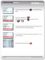
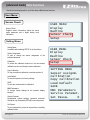
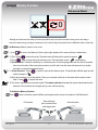
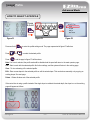
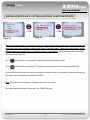
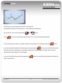
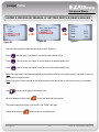
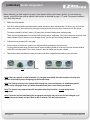
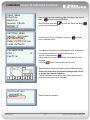
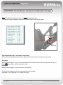
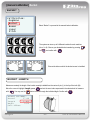
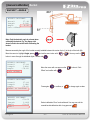
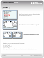
User Manual
manual version
Advanced Mode
2.1A
software version
EZ02_01
Content
Advanced Mode
Activation..................................…………....3
Extra Functions………………………........4-7
Setting Menu
Copy Calibration…………...........................41
Load Default.......……………...............……42
Save………..................................…………42
MMI Parameters……….........................43-44
Service Parameters......................…………44
Set Password.............................................45
Sensor Check.............................................45
Usage
Zeroing the target reach………..……..........8
Set the Reach Reference………………......9
Maximum Height Function………………...10
Maximum Depth Function…………………11
Memory Function…………………………..12
Profile………………………..............…13-16
Manual Calibration
Sensor Assignment…………………….17-18
Access to Calibration Functions...........19-20
Dog Bone………………….........................21
Bucket………………….....................…22-23
Booms…………………………...................24
Main Boom…………...................…25
Articulated Boom...........................26
Dipper Stick...................................27
Measuring Hints........................28-29
Laser Receiver..........................30-34
Pitch..........................................35-40
EZDigPro
-2-
User & Calibration Manual
[advanced mode] Activation
USER MENU
Display
Machine
Setup
Advan.Mode
USER MENU
Display
Machine
Setup
Advan.Mode
USER MENU
Display
Machine
Sensor Check
Setup
Advan.Mode
USER MENU
Display
Machine
Setup
Advan.Mode
From any operating screen, press & hold
OFF
appears.
Move down to “Advan.Mode” with
OFF
Select “Advan.Mode” by pressing
with
- or
Enter
.
to be able to select “ON”
.
Once selected, you’ll see a new menu point (“Sensor Check”) appear, and one
of the 3 bottom LEDs on the remote display will light up.
ON
You can disable the advanced mode again by choosing “OFF” in the
“Advan.Mode” setting.
OFF
Exit the User Menu by pressing & holding
EZDigPro
until the USER MENU page
Enter
-3-
.
User & Calibration Manual
[advanced mode] Extra Functions
Once you enabled the advanced mode, you’ll have the following extra functionality on hand:
REMOTE DISPLAY
Red: too high, move the bucket down.
Depth
Green: on grade.
Red: too low, move the bucket up.
Advanced Mode only:
Reach Information
Controlbox
Depth
Reach information:
Indicates the horizontal distance of the bucket tip
or blade in relation to a previously defined point.
Reach
Slope
EZDigPro
-4-
User & Calibration Manual
[advanced mode] Extra Functions
Beside the new display options, you’ll also have additional new functions:
Max. Height / Max. Depth Alarm:
Max. Height / Max. Depth Alarm:
Informs the operator optically and acoustically if a
previously defined max. height or max. depth has
been reached or exceeded.
0
Caution:
Although you can use this function to set a maximum height warning, this is not a fail-safe security function and
can’t replace systems that have automatic shut-off. If you are working in a hazardous area, such as under power
lines, you should be using a more secure warning system.
Memory:
Memory:
Enables the operator to compensate a machine’s
elevation change, if he intends (or is forced) to
work without a rotating laser.
0
Caution:
Although you can use this function to compensate a machine’s elevation change without using a rotational laser, it
is not recommended in general, as this principle easily leads to inaccuracies. Better use the laser receiver to
compensate.
EZDigPro
-5-
User & Calibration Manual
[advanced mode] Extra Functions
Beside the new display options, you’ll also have additional new functions:
Pitch Sensor:
Calibration:
DogBone
Bucket
Booms
Laser
Pitch
Pitch Sensor:
A fourth or fifth sensor may be used as a pitch
sensor to compensate tilting forward or backward
movements of the whole machine.
Caution:
Although you can use this function to compensate tilting forward or backward movements of the whole machine,
the pitch sensor is NOT able to compensate a chassis rotation while you’re working with a preset slope.
Profile:
Profile:
Enables the operator to define and work in a profile.
EZDigPro
-6-
User & Calibration Manual
[advanced mode] Extra Functions
Beside the new display options, you’ll also have additional new functions:
User Menu:
Sensor Check:
USER MENU
Display
Machine
Sensor Check
Setup
Sensor Check:
Supplies sensor informations about the actual
angle measured, and a digital battery level
information.
Setting Menu:
Setting Menu:
Accessible after selecting SETUP in the User Menu.
Sensor Assignment:
To add or change the sensor assignment of the
individual elements.
Calibration:
To access the calibration section incl. the new manual
calibration section and the pitch sensor calibration.
Copy Calibration:
To copy a machine’s calibration to another machine #.
Load Default:
To reset the system to its factory settings.
SAVE:
To save the actual machine’s calibration.
MMI Parameters:
To change certain settings for the system’s display
behavior.
Service Paramet.:
Fundamental system settings, password protected.
Should be only accessed by EZDigPro service partners.
USER MENU
Display
Machine
Sensor Check
Setup
SETTING MENU
Sensor Assignm.
Calibration
Copy Calibration
Load Default
SAVE
MMI Parameters
Service Paramet.
Set Passw.
0
Set Passw.:
To set a password to protect the system from overwriting
calibration data.
EZDigPro
-7-
User & Calibration Manual
[usage] Zeroing the Target Reach
Advanced Mode
REACH
A
Bucket on grade:
Zero reach.
Position the bucket on the ground on a desired reference point and press & hold the
key for a couple of
seconds to zero the reach value.
Now the reach value will be zero at that distance (even in other depth positions) and the distance value to that point
will be shown if the bucket is further away (positive) or closer (negative) to the cab.
A
Bucket on the reach
zero reference
EZDigPro
Bucket too far,
Positive reach
-8-
A
Bucket too close.
Negative reach
A
User & Calibration Manual
[usage] Set the Reach Reference
Advanced Mode
REACH
Press & hold
to enter the reach setting mode. The correspondent value will flash.
To set the reach reference, use these buttons:
Press
-
or
to set the desired value.
Press
to invert the sign (positive / negative).
Press
to zero the value.
Press
Enter
to confirm the value and end the setting mode.
The shown reach is now the distance from the actual bucket position to the target reach.
If the bucket is closer to the cab in respect to the target reach, the value is negative and vice-versa.
Note: The direction of the reach is indicated by the reach icon (arrow), based on the assumption that the control box is
mounted on the right-hand side of the driver in the cab. Same for the remote display’s LED indication.
EZDigPro
-9-
User & Calibration Manual
[usage] Max. Height Function
Advanced Mode
0
Caution:
Although you can use this function to set a maximum height warning, this is not a fail-safe security function and
can’t replace systems that have automatic shut-off. If you are working in a hazardous area, such as under power
lines, you should be using a more secure warning system.
Function disabled.
There’s no max height set.
With the icon flashing, move the boom to the maximum height that you want or can reach safely depending on
your work environment.
Press
to set this point as maximum height.
Enter
Function enabled (in use)
When the highest machine pivot is as high or higher than the max height set,
an alarm will sound and the display will have the following warning:
Move the booms down to return to the previous screen (max height not reached).
To disable the Max Height function once the alarm is activated, press and hold
The icon
.
will appear on the Max. Height settings page as a confirmation.
Enter
To disable the Max. Height function in general, enter with the arrow keys the according screen, press
to make the Min./Max. Height screen blink, press once the right up arrow key
and confirm with
Enter
.
The following screen confirms that you’ve disabled the Max. Height alarm:
EZDigPro
- 10 -
User & Calibration Manual
[usage] Max. Depth Function
Advanced Mode
0
Caution:
Although you can use this function to set a maximum depth warning, this is not a fail-safe security function and
can’t replace systems that have automatic shut-off. If you are working in a hazardous area, such as around gas
lines, you should be using a more secure warning system.
Function disabled.
There’s no max depth set.
With the icon flashing, move the bucket to the maximum depth that you want or can safely reach depending on
your work environment.
Press
to set this point as the maximum depth (which means the same as “minimum height” MIN).
Enter
Function enabled (in use)
When the bucket blade (or teeth) is at the same depth or lower than the maximum
depth set, an alarm will sound and the display will have the following warning:
Move the booms down to return to the previous screen (max depth not reached).
To disable the Max Depth function once the alarm is activated, press and hold
The icon
.
will appear on the Max. Depth settings page as a confirmation.
Enter
To disable the Max. Depth function in general, enter with the arrow keys the according screen, press
- and confirm with
to make the Min./Max. Height screen blink, press once the left up arrow key
Enter
.
The following screen confirms that you’ve disabled the Max. Depth alarm:
EZDigPro
- 11 -
User & Calibration Manual
[usage] Memory Function
Advanced Mode
0
Although not often used, the memory function provides a way to move the excavator when you are not using a
laser as a reference (eg: moving the excavator on its tracks to dig to the same level at a different location on the site).
0
No Reference: Memory function is not in use.
0
1.) Use
1
2.) Then, press Enter to enter this mode. The bold border will flash and the symbol changes to
3.) Press Enter again to begin setting the reference point. The bold border around
stops flashing.
-
to move to the Memory Function (lower right quadrant of the screen will have a bold border).
4.) “Set Reference:” Position the bucket tip on a reference point. Choose anything stable that can also be accessed
from the next location. After moving the excavator, you will need to use this same reference point (or another
point that is at exactly the same elevation).
2
5.) “Keep Reference:” Press
Enter
to save the value at this reference point. The bold border will flash again and the
symbol changes to
6.) Move the excavator to your next position. Place your excavator bucket tip on that same reference point used in
Step 4. Press
Enter
to acquire the value.
3 7) The arrow is replaced by an excavator symbol. The memory function is in use (the system understands that the
elevation of the excavator has changed) and you can continue working.
To disable the Memory Function:
Press
Enter
and the excavator symbol will flash; press again and the arrows icon replaces it (“No Reference”).
First location
EZDigPro
Same reference
point, accessed from
both digging sites
- 12 -
Second location
User & Calibration Manual
[usage] Profile
Advanced Mode
HOW TO SELECT A PROFILE
Press
& hold
Enter
%
Figure P1
Figure P2
Press and hold
-
Press
Press
Enter
%
or
Profile:
Use
View
Edit
Delete
Figure P3
to enter the profile setting mode. The page represented in figure P2 will show.
to select the desired profile.
and the page in figure P3 will be shown.
Note: If no icon is selected, the profile mode will be disabled and the panel will return to the main operator page.
Use – Start to work with the selected profile. No further settings, and the system will return in the working page.
View – To view a drawing of the selected profile.
Edit – Enter a new shape for the selected profile or edit the actual shape. This can be done manually or by copying an
existing shape. See next page.
Delete – Delete all values set of the selected profile.
If the control box is using a profile instead of the single slope to calculate the actual depth, the slope icon on the working
page will appear as follows:
EZDigPro
- 13 -
User & Calibration Manual
[usage] Profile
Advanced Mode
ENTER A PROFILE BY COPYING EXISTING JUNCTION POINTS
Profile:
Use
View
Edit
Delete
Enter
Set the profile:
Automatic
Manual
Figure P4
Figure P3
Enter
Take a point ?
Acquire P
1
End Profile
Figure P5
Start by putting the bucket on any profile point (e.g. the point furthest away from the cab), zeroing the depth and
reach value on the main operator working screen (figure P1 on earlier page). Choose this point carefully, as this
will be the point you’ll need to refer on each time you move your machine. Select the desired profile as described
previously to reach Figure P2.
Press
Enter
Press
Enter
with the cursor over “Automatic” to enter into the profile “self learning” mode.
with the cursor over “Acquire P” to acquire the actual bucket position as the selected profile point.
You can now move the bucket to the next point (actual point number is shown on the same line). When the last point has
been taken, stop the acquisition by choosing “End Profile.”
Note: If the points are not in sequence, the display will show an error screen
The profile shape will be shown on the screen. See “Profile View” page.
EZDigPro
- 14 -
User & Calibration Manual
[usage] Profile
Advanced Mode
4
2
1
3
On this page, you can see a graphical summary of the profile set.
Starting from the left side of the screen (point 1), the line follows the settings done.
You can zoom in / zoom out on the graph with
Press
- or
buttons.
to exit to the profile menu page and select “Use” to use the previously defined profile.
Once you moved your machine, you are able to define your new position to the profile by pressing the
If you set your profile the automatic (self-learning) way, after pressing the
button.
button, your actual bucket tip’s position
will be the zero point you defined prior to entering the profile mode, zeroing the depth and reach value on the main
operator working screen (figure P1 on earlier page).
If you set your profile the manual way, after pressing the
button, your actual bucket tip’s position will be the point
with the coordinates 0/0.
EZDigPro
- 15 -
User & Calibration Manual
[usage] Profile
Advanced Mode
ENTER A PROFILE BY MANUALLY SETTING DEPTH & REACH VALUES
Profile:
Use
View
Edit
Delete
Enter
Set the profile:
Automatic
Manual
PROFILE:
Point:
Depth
Reach
Slope
Enter
Figure P6
Figure P3
1
1
0.000
0.000
0.00
Figure P7
Select the desired profile as described previously to reach Figure P2.
Press
Enter
with the cursor over “Manual” to enter the profile “manual” mode.
Press
Enter
with the cursor over “Depth” to set the depth of the selected profile point.
Press
Enter
with the cursor over “Reach” to set the reach of the selected profile point.
Note: The slope value is calculated automatically by the software referring to the previous point in the profile. You are not
able to edit or change this value.
Note: Choose the 0/0 point carefully, as this will be the point you’ll need to refer on each time you move your machine.
Use
- at the end of the page to set the next point.
When all settings are done, press
to exit from the profile setting mode.
The profile shape will be shown on the screen. See “Profile View” page.
Another short press on
EZDigPro
leads you back to the profile menu.
- 16 -
User & Calibration Manual
[calibration] Sensor Assignment
Before calibrating, you must assign the sensors to each element and then place them in position. You can choose any
element, except for the laser receiver (select the best location as described on page 11-17 under "Components Installation“
of the Basic User Manual).
1.
Select one of the sensors.
2.
Put it in a horizontal position and make sure the other sensors are all in vertical position. To do this, you can leave the
others in the case in their vertical slots, and lay the selected sensor flat on top of the case foam or on the ground.
The sensors should be at least 1 meter (3 ft.) away from the remote display when assigning them.
There must be only one sensor in horizontal position during sensor assignment. If any of the others are horizontal, it will
cause problems. Even if there is no error message shown, you may get errors during calibration or operation.
3.
Follow the menu prompts on the next page.
4.
Put that sensor on the boom or location you assigned before proceeding to the next sensor.
For the greatest capture range, the laser receiver sensor should be placed on the boom so that the detection window
will be 90 to the laser plane. For the other sensors, it does not matter how they are oriented.
5.
Take another sensor and follow the same procedure, until all are assigned and in position on the excavator.
Programming condition: only one sensor horizontal.
Work condition: all sensors vertical
Note: If there are sensors on other machines or in carrying cases within the radio reception area, they also
must be vertical while you are assigning your horizontal sensor.
Note: Don’t assign a sensor to an element which already has a sensor assigned to it. A dedicated graphic
(shown on the next page) shows you which elements already have a sensor being assigned to.
Note: The sensors only communicate with the system when they’re vertical – except during sensor
assignment.
Note: If a sensor can’t be found during the assignment procedure, and you’re sure it’s fully charged, try to
take out the sensor battery and put it back in after 5 seconds. This will reset the sensor.
EZDigPro
- 17 -
User & Calibration Manual
[calibration] Sensor Assignment
Follow these menu prompts to assign each sensor:
SENSOR ASSIGNM.
Put one sensor
horizontal.
ENTER: continue
ZERO: exit
Enter
SENSOR ASSIGNM.
Wait Please...
This seeking process usually only takes
10-20 seconds. Only in case of
communication problems it might take
longer.
Sensor blinking: Actual assignment
proposal.
Sensor black: Already another sensor
being assigned to.
Sensor white: Free element to assign the
actual sensor to.
SENSOR ASSIGNM.
Searching
sensor...
150
NOT FOUND
SENSOR ASSIGNM.
No sensor ready
to be programmed
ZERO: exit
FOUND
ASSIGN TO:
ENTER TO CONFIRM
Enter
This programming routine usually also
only takes 10-20 seconds. Only in case of
communication problems it might take
longer.
SENSOR ASSIGNM.
Programming…
Please Wait
NO
PROGRAMMING
SUCCESSFUL ?
SENSOR ASSIGNM.
Programming
FAIL !
ZERO to exit
YES
SENSOR ASSIGNM.
Sensor
programming OK !
ZERO to exit
After the sensor assignment – or before the next-day setup – you can verify the sensor assignment with the help of the
Sensor Check section on page 45 by rotating a sensor (in vertical) with your hand. The value that changes the most
indicates which sensor you’re actually using.
EZDigPro
- 18 -
User & Calibration Manual
[calibration] Access To Calibration Functions
USER MENU
Display
Machine
Sensor Check
Setup
From the working screen (operator mode) or the alarm page, press &
Enter
hold
to enter into the USER MENU.
Scroll the cursor down with
to enter into the setting menu.
SETTING MENU
Sensor Assignm.
Calibration
Copy Calibration
Load Default
CALIBRATION
PIN :
Confirm
-
to reach the “Setup” line. Press
Scroll the cursor down to “Calibration” and press
into the calibration menu.
0
Enter
Enter
to enter
If a calibration password is not needed (default mode), skip this part.
If a password has been set, the system will prompt for it.
Scroll to Confirm and press Enter
If the password is incorrect, the message “Access denied!” will be
displayed.
Press the
button to return to the operation mode.
Machine selection page at the beginning of the calibration section.
Please refer to the basic user manual (starting at page 19) how
to perform the automatic calibration.
This advanced user manual will continue to describe the manual
calibration and the pitch sensor calibration.
.
.
.
Calibration:
Automatic
Manual
EZDigPro
Select the manual calibration.
- 19 -
User & Calibration Manual
[calibration] Access To Calibration Functions
Calibration:
DogBone
Bucket
Booms
Laser
Pitch
In the manual calibration section you’re able to calibrate all elements
(Dog Bone, Bucket, Booms (Dipper Stick, Articulated Boom, Main
Boom), Laser Receiver and the Chassis (Pitch Sensor) manually.
Calibration:
DogBone
Bucket
Booms
Laser
Pitch
Select “DogBone” to proceed to the manual Dog Bone calibration.
EZDigPro
- 20 -
User & Calibration Manual
[manual calibration] Dog Bone
DOG BONE - Bucket Sensor mounted on the Bucket Leverage
Note: The Dog Bone calibration must be done before the bucket calibration.
Changing the dog bone calibration means that the bucket calibration has to be done again.
DOG BONE CALIBR.
Seg1Length 0.000
Seg2Length 0.000
Seg3Length 0.000
Seg4Length 0.000
Seg1Angle
0.00
-Offset
0.00
-Actual
0.00
Seg2Angle
0.00
-Offset
0.00
-Actual
0.00
Seg1Angle
Seg2Angle
Seg1Length (Seg2Length – Seg3Length – Seg4Length)
Measure the four segments (the bones) of the dog bone and set into the proper line referring to the picture.
Seg1Angle:
Measure the real segment 1 angle, use same techniques used to measure machine’s booms angles from pivot to pivot.
Press Enter when ready to take the correct offset value.
Seg2Angle:
Measure the real segment 2 angle as done above for segment 1.
(To measure the angles correctly, use as an example the above drawing:
Seg1Angle = + 85°; Seg2Angle = - 40° (Watch the signs!))
EZDigPro
- 21 -
User & Calibration Manual
[manual calibration] Bucket
BUCKET
Calibration:
DogBone
Bucket
Booms
Laser
Pitch
Select “Bucket” to proceed to the manual bucket calibration.
The system can store up to 8 different buckets for each machine
(from 1 to 8). Choose your desired bucket number by pressing
Or
and confirm with
-
Enter
Choose the side on which the bucket sensor is installed.
SENSOR
SIDE
SENSOR
SIDE
BUCKET - LENGTH
Measure accurately the length of the bucket currently installed from the center of pin (L) to the tip of the tooth (M).
Move the cursor to highlight Length, press
with
. You may use the
Enter
and set the exact value expressed in the selected unit of measure
button to move through the individual digits. Confirm with
Enter
.
BUCKET CALIBRAT.
Actual
37.49
Length
1.480
Angle
0.00
Calc Offset
EZDigPro
- 22 -
User & Calibration Manual
[manual calibration] Bucket
BUCKET - ANGLE
BUCKET CALIBRAT.
Actual
37.49
Length
0.000
Angle
0.00
Calc Offset
Fig.10
Note: Only the bucket’s angle is relevant when
calibrating the bucket. E.g. the dipper stick
doesn’t need to be vertical while calibrating the
bucket.
Measure accurately the angle of the bucket currently installed between the center of pin (L) to the tip of the tooth (M).
Move the cursor to highlight Angle, press
Enter
and set the exact value with
button to move through the individual digits. Confirm with
BUCKET CALIBRAT.
Actual
37.49
Length
1.480
Angle
-79.60
Calc Offset
BUCKET CALIBRAT.
Actual
37.49
Length
1.480
Angle
-79.60
Enter to Confirm
BUCKET CALIBRAT.
Actual
-79.60
Length
1.480
Angle
-79.60
Done!
EZDigPro
Enter
or
-
. You may use the
.
Move the cursor with one press on the
Offset” and confirm with
Press again
Enter
Enter
-
button to “Calc
.
to confirm, or
to change again a value.
Bucket calibration “Done” and confirmed. You may now exit the
manual bucket calibration with a long press on
- 23 -
.
User & Calibration Manual
[manual calibration] Booms
BOOMS
Calibration:
DogBone
Bucket
Booms
Laser
Pitch
Select “Booms” to proceed to the manual calibration of the dipper
stick, articulated boom and main boom.
Choose either the main boom, articulated boom or dipper stick.
BOOM SELECTION
Choose the side on which the sensor is installed.
SENSOR
SIDE
SENSOR
SIDE
Depending on your choice, please proceed on the following pages:
Main Boom: Page 25
Articulated Boom: Page 26
Dipper Stick: Page 27
Refer to page 18 of the Basic User Manual in case of uncertainties about the individual element’s names.
EZDigPro
- 24 -
User & Calibration Manual
[manual calibration] Main Boom
Main Boom - LENGTH
Measure accurately the length of the main boom between the center of pivot A and the center of pivot B.
Move the cursor to highlight Length and set the exact value expressed in the selected unit of measure.
Main B.CALIBRAT.
Actual
16.60
Length
6.680
Angle
0.00
Calc Offset
Main Boom Length
Main Boom Angle
Main Boom - ANGLE
Main B.CALIBRAT.
Actual
37.49
Length
4.480
Angle
15.90
Calc Offset
Measure accurately the angle of the main boom between the centers of pins A
and B.
Move the cursor to highlight Angle, press
with
-
or
. You may use the
individual digits. Confirm with
Main B.CALIBRAT.
Actual
37.49
Length
4.480
Angle
15.90
Calc Offset
Main B.CALIBRAT.
Actual
37.49
Length
4.480
Angle
15.90
Enter to Confirm
Main B.CALIBRAT.
Actual
15.90
Length
1.480
Angle
15.90
Done!
EZDigPro
Enter
Press again
Enter
Enter
and set the exact value
button to move through the
.
Move the cursor with one press on the
confirm with
Enter
-
button to “Calc Offset” and
.
to confirm, or
to change again a value.
Main Boom calibration “Done” and confirmed. You may now exit the manual
main boom calibration with a long press on
- 25 -
.
User & Calibration Manual
[manual calibration] Articulated Boom
Articulated Boom - LENGTH
Measure accurately the length of the articulated boom between the center of pivot E and the center of pivot F.
Move the cursor to highlight Length and set the exact value expressed in the selected unit of measure.
Art. B.CALIBRAT.
Actual
-9.60
Length
2.340
Angle
0.00
Calc Offset
Length
Articulated boom
Angle
Articulated
boom
Articulated Boom - ANGLE
Art. B.CALIBRAT.
Actual
-9.60
Length
2.340
Angle
-15.90
Calc Offset
Art. B.CALIBRAT.
Actual
16.60
Length
2.340
Angle
-15.90
Calc Offset
Art. B.CALIBRAT.
Actual
16.60
Length
2.340
Angle
-15.90
Enter to Confirm
Art. B.CALIBRAT.
Actual
-15.90
Length
2.340
Angle
-15.90
Done!
EZDigPro
Measure accurately the angle of the main boom between the centers of pins
E and F.
Move the cursor to highlight Angle, press
with
-
or
. You may use the
individual digits. Confirm with
Enter
Press again
Enter
Enter
and set the exact value
button to move through the
.
Move the cursor with one press on the
confirm with
Enter
-
button to “Calc Offset” and
.
to confirm, or
to change again a value.
Articulated Boom calibration “Done” and confirmed. You may now exit the
manual articulated boom calibration with a long press on
- 26 -
.
User & Calibration Manual
[manual calibration] Dipper Stick
Dipper Stick - LENGTH
Measure accurately the length of the dipper stick between the center of pivot G and the center of pivot H.
Move the cursor to highlight Length and set the exact value expressed in the selected unit of measure.
DIPPER CALIBRAT.
Actual
-66.66
Length
3.010
Angle
0.00
Calc Offset
Length
Dipper stick
Angle
Dipper stick
Dipper Stick - ANGLE
DIPPER CALIBRAT.
Actual
-66.66
Length
3.010
Angle
-85.87
Calc Offset
DIPPER CALIBRAT.
Actual
-66.66
Length
3.010
Angle
-85.87
Calc Offset
DIPPER CALIBRAT.
Actual
-66.66
Length
3.010
Angle
-85.87
Enter to Confirm
DIPPER CALIBRAT.
Actual
-85.87
Length
3.010
Angle
-85.87
Done!
EZDigPro
Measure accurately the angle of the dipper stick between the centers of pins
G and H.
Move the cursor to highlight Angle, press
with
-
or
. You may use the
individual digits. Confirm with
Enter
Press again
Enter
Enter
and set the exact value
button to move through the
.
Move the cursor with one press on the
confirm with
Enter
-
button to “Calc Offset” and
.
to confirm, or
to change again a value.
Dipper Stick calibration “Done” and confirmed. You may now exit the manual
dipper stick calibration with a long press on
- 27 -
.
User & Calibration Manual
[manual calibration] Measuring Hints
MEASURING ANGLES
METHOD 1
Place a straight edge from center of pivot A to center of pivot B and using an inclinometer, read the actual angle (Fig.2).
Fig.2
METHOD 2
If a tripod with laser transmitter and visible beam is available, the previous procedure could be executed by the alignment
of the points A and B to the horizontal plane of the transmitter; first by pointing the beam on point A (moving up and down
the laser) and then moving the boom until the point B is again spotted by the beam. In this case the angle value to be
entered is 0.0 (0 degrees).
The same procedure could be used for other booms. If it is not possible to reach the horizontal position, rotate the laser
90 degrees in order to generate a vertical plane and align the boom A and B point (i.e. stick or bucket) to a vertical plane
again by fixing A point first and then B. In this case the angle value to be entered is –90.0 degrees. Watch the sign!
EZDigPro
- 28 -
User & Calibration Manual
[manual calibration] Measuring Hints
MEASURING ANGLES
METHOD 3
The vertical alignment could be also obtained by using the plumb bob method.
Note: When the boom is horizontal the angle is zero; when
pivot M is lower than L, the angle is negative and when pivot
M is higher than L, the angle is positive.
EZDigPro
- 29 -
Fig.10
User & Calibration Manual
[manual calibration] Laser Receiver
LASER RECEIVER
LASER CALIBRAT.
Position
Parameters
Choose “Position” to start to calibrate the laser receiver.
Choose with the up and down arrow keys on which element the laser
receiver is attached to. Confirm with
Enter
.
Boom Selection
HoriDist
This value indicates the distance between A and C (ref. drawings in fig 11 – fig
20 in the following pages). This point is obtained at the intersection on the
LASER RECEIVER
HoriDist 0.000
VertDist 0.000
projected line A-B by the perpendicular through center of the Laser Receiver.
Insert the relevant value in meters or feet.
VertDist
This value corresponds to the distance between E and D (center of Laser
Receiver to point D on projection AB, ref. Fig.11 – Fig.20).
Insert the relevant value in meters or feet.
Confirm each setting with
Enter
and leave the page by pressing 3 times
Note: Be careful to dial in the correct sign especially for the vertical distance
(E-D). Refer to the following drawings.
EZDigPro
- 30 -
User & Calibration Manual
[manual calibration] Laser Receiver
LASER RECEIVER
LASER CALIBRAT.
Position
Parameters
Choose “Parameters” to change the settings of the laser receiver.
Speed Comp:
A default, well tested, speed compensation value to minimize errors
resulting out of a dynamic laser catch, using the laser rabbit mode. Refer
to page 55 of the basic user manual. It is recommended not to change this
value.
LASER PARAMETERS
Speed Comp
2
LasVelMax
50
LasTimeOut
150
AngoloACQ
5000
LasVelMax:
Maximum accepted vertical speed of the laser during the laser catch.
Increasing this value will increase the max. accepted speed.
LasTimeOut:
The time the system waits for the laser beam to touch the laser receiver
after pressing the laser button. Default setting: 150 (15 seconds).
AngoloACQ:
Max. accepted angle of the laser receiver during the laser catch. Default
setting: 500 (45°). It is recommended not to change this value.
EZDigPro
- 31 -
User & Calibration Manual
[manual calibration] Laser Receiver
REFERENCE DRAWINGS TO DETERMINE POSITION OF LASER RECEIVER
MAIN BOOM
Fig.11
VERTICAL DISTANCE = DE
HORIZONTAL DISTANCE = AC
Note: In the example drawing above (Fig. 11), AC is positive and DE is positive
EZDigPro
- 32 -
User & Calibration Manual
[manual calibration] Laser Receiver
REFERENCE DRAWINGS TO DETERMINE POSITION OF LASER RECEIVER
ARTICULATED BOOM
Fig.15
VERTICAL DISTANCE = DE = Positive
Fig.16
VERTICAL DISTANCE = DE = 0
Fig.17
VERTICAL DISTANCE = DE = Negative
HORIZONTAL DISTANCE = AC
Note: In the example drawings above, AC is always positive
EZDigPro
- 33 -
User & Calibration Manual
[manual calibration] Laser Receiver
REFERENCE DRAWINGS TO DETERMINE POSITION OF LASER RECEIVER
DIPPER STICK
Fig.18
Fig.19
Fig.20
VERTICAL DISTANCE = DE = Negative
VERTICAL DISTANCE = DE = Positive
VERTICAL DISTANCE = DE = 0
HORIZONTAL DISTANCE = AC
Note: In the example drawings above, AC is always positive
EZDigPro
- 34 -
User & Calibration Manual
[manual calibration] Pitch Sensor
If a rotation of the chassis during operation shall be compensated, you may use a fourth (or fifth) sensor as a “pitch”
sensor for the chassis. This will automatically correct forward and backward tilting movements of your machine as well
as rotation effecting your actual depth information.
The following section describes how to install, calibrate and (de-)activate the pitch sensor.
Note: In order to use the pitch option, your system needs to contain 4 (if your machine just has one main boom) or 5 (if
your machine has an additional articulated boom) sensors in total. If you’re missing this one extra sensor, simply order
it at your local EZDigPro dealer.
Note: The pitch calibration section is only available if using the “Advanced Mode”. After calibration you may use the
pitch sensor as well in the “Basic Mode”.
From the working screen (operator mode) or the alarm page, press &
Enter
hold
to enter into the USER MENU.
USER MENU
Display
Machine
Sensors Check
Setup
Scroll down to “Setup” and confirm with
SETTING MENU
Sensor Assignm.
Calibration
Copy Calibration
Load Default
Scroll down to “Calibration” and confirm with
Enter
.
Enter
.
Select your machine #.
EZDigPro
- 35 -
User & Calibration Manual
[manual calibration] Pitch Sensor
This Machine is
already cal.
-Sel. New Mach
-Overwrite
If the machine selected already contains calibration data (which should
be the case if you want to add the pitch sensor to an already calibrated
system), the system informs you accordingly. Choose “Overwrite”.
This Machine is
already cal.
-Sel. New Mach
Enter to Confirm
Machine:
3 Elements
4 Elements
“Overwrite” asks you to confirm your choice by pressing
Select and confirm the number of elements you have on your machine.
3 Elements: If your machine has just one main boom.
4 Elements: If your machine has an additional articulated boom.
Perform & pass the vibration test.
ENTER: CONTINUE
Refer to the vibration test section in the basic user manual for details.
Note: The pitch sensor should be in a horizontal position during this
whole preparation process.
ENTER: CONTINUE
40 %
Please Wait...
Calibration:
Automatic
Manual
EZDigPro
Choose & select “Manual”.
- 36 -
User & Calibration Manual
[manual calibration] Pitch Sensor
Calibration:
DogBone
Bucket
Booms
Laser
Pitch
PITCH CAL.
Assignment
Easy Calib.
Manual Calib.
Enable
OFF
SENSOR ASSIGNM.
Put one sensor
horizontal.
ENTER: continue
ZERO: exit
Choose & select “Pitch”.
Choose & select “Assignment”.
If your chassis sensor has been already assigned during a previous calibration
(e.g. on another machine), you may skip this section and continue to the
calibration part.
Assign the pitch sensor.
Refer to the assignment section of this advanced user manual for details.
After you’ve performed the assignment, attach the chassis sensor on any place
at the chassis (upper cab – NOT lower cab!) in a way, that it’s vertically
orientated such as the other sensors on the booms.
Note: DO NOT attach the sensor to the chassis with the “nose” pointing down
(to the ground)!
PITCH CAL.
Assignment
Easy Calib.
Manual Calib.
Enable
OFF
BAD
GOOD
GOOD
GOOD
You may now calibrate the chassis sensor with an “Easy Calibration”
(recommended) or “Manual Calibration”. The “Manual Calibration will be
described at page 40. Choose & select “Easy Calib.”
SENSOR
SIDE
PITCH CALIBRAT.
Seg. AB
0.000
Seg. BC
0.000
Continue
EZDigPro
Choose on which side of the chassis you’ve attached the pitch sensor.
Refer to the drawing on the next page which values to put in for “Seg. AB” and
“Seg. BC”.
- 37 -
User & Calibration Manual
[manual calibration] Pitch Sensor
Examples:
A: Rotational center of the machine (in the
example on the left the pivot point of the chassis to
the undercarriage)
C: Pivot point of the main boom and the chassis
C
A
B: Intersection of the horizontal axis going through
“A” and the vertical axis going through “C”
B
Note: AB is positive, if B is more in front of the
machine. BC is positive, if C is higher than B – in
this case both are positive.
If you’d like to compensate tilting movements
rotating over the back of the tracks, choose “A” as
C
shown on the example on the left.
AB = positive
BC = positive
A
If you’d like to compensate tilting movements
B
rotating over the front of the tracks, choose “A” as
shown on the example on the left.
AB = negative
C
BC = positive
Note: AB and BC are only related to the machine
itself – NOT the location of the chassis sensor!
B
A
PITCH CALIBRAT.
Seg. AB
0.250
Seg. BC
0.840
Continue
Measure and dial in AB & BC as prompted.
Select and confirm “Continue”
Note: You may change this values any time again,
depending which tilting movements you’d like to
compensate.
EZDigPro
- 38 -
User & Calibration Manual
[manual calibration] Pitch Sensor
Final step is to calibrate the pitch’s offset angle. For this you need to rotate the
machine’s cabin (only the upper cab) 180° after getting prompted for it. So be
sure to have your machine (not moving, with an adequate machine engine
ENTER: CONTINUE
ROTATE COCKPIT
180°
speed) in an according position to be able to rotate later, prior to pressing
Press
Enter
Enter
to confirm the 1st position.
Rotate only the cabin 180°. All the other elements may be moved as well to
ensure not to accidentally touch anything around.
ENTER: CONTINUE
Press
Enter
to confirm the 2nd position.
ENTER: CONTINUE
Calibration
Done!
PITCH CAL.
Assignment
Easy Calib.
Manual Calib.
Enable
ON
SaveCalibration?
Yes
No
You successfully calibrated the pitch sensor.
The pitch calibration screen appears again. Note, that the pitch sensor is
automatically enabled (“ON”). You may disable the pitch sensor any time by
scrolling to “Enable” and set the value to “OFF”.
You may exit the pitch calibration screen by short-press of
Enter
(2 times) and
save your new calibration.
EZDigPro
- 39 -
User & Calibration Manual
[manual calibration] Pitch Sensor
Manual Pitch Calibration
PITCH CAL.
Assignment
Easy Calib.
Manual Calib.
Enable
OFF
After you’ve performed the assignment, attach the chassis sensor on any place
at the chassis (upper cab – NOT lower cab!) in a way, that it’s vertically
orientated such as the other sensors on the booms.
You may now calibrate the chassis sensor with an “Easy Calibration”
(recommended) or “Manual Calibration”. The “Manual Calibration will be
PITCH CALIBRAT.
SIDE:
L
Seg. AB
0.000
Seg. BC
0.000
Act. Ang.-179.81
Angle
-0.09
Calc Offset
PITCH CALIBRAT.
SIDE:
L
Seg. AB
0.250
Seg. BC
0.840
Act. Ang.-179.81
Angle
-0.09
Calc Offset
PITCH CALIBRAT.
SIDE:
L
Seg. AB
0.250
Seg. BC
0.840
Act. Ang.-179.81
Angle
77.50
Calc Offset
PITCH CALIBRAT.
Seg. BC
0.840
Act. Ang.-179.81
Angle
77.50
Calc Offset
PITCH CALIBRAT.
Seg. BC
0.840
Act. Ang. 77.50
Angle
77.50
Done!
EZDigPro
described now. Choose & select “Manual Calib.”
Choose on which side of the chassis you’ve attached the pitch sensor. On the
left (L) or on the right (R).
Refer to the drawing on page 38 which values to put in for “Seg. AB” and “Seg.
BC”.
Measure accurately the angle between AC and the horizontal axis.
Move the cursor to highlight Angle, press
with
-
or
. You may use the
individual digits. Confirm with
Enter
Press again
Enter
Enter
and set the exact value
button to move through the
.
Move the cursor with one press on the
confirm with
Enter
-
button to “Calc Offset” and
.
to confirm, or
to change again a value.
“Done!” indicates the success of your manual pitch calibration.
- 40 -
User & Calibration Manual
[setting menu] Copy Calibration
USER MENU
Display
Machine
Sensor Check
Setup
From the working screen (operator mode) or the alarm page, press &
Enter
hold
to enter into the USER MENU.
Scroll the cursor down with
to enter into the setting menu.
-
to reach the “Setup” line. Press
SETTING MENU
Sensor Assignm.
Calibration
Copy Calibration
Load Default
Scroll the cursor down to “Copy Calibration” and press
enter this menu point.
MACHINE COPY
Copy from:
Paste to :
COPY
SAVE
Select “Copy from” with the arrow keys and confirm with Enter .
Change the machine # with the arrow keys, e.g. to machine #2 and
confirm with Enter .
Select “Paste to” with the arrow keys and confirm with Enter .
Change the machine # with the arrow keys, e.g. to machine #5 and
confirm with Enter .
MACHINE COPY
Copy from:
Paste to :
COPY
SAVE
MACHINE COPY
Copy from:
Paste to :
COPY
SAVE
2
5
2
5
to
Perform the copy operation by selecting “COPY” with the arrow keys
and press Enter .
When prompted “Enter to Confirm”, re-confirm by pressing
Enter
.
“Done!” communicates the success of your operation.
2
5
SETTING MENU
Sensor Assignm.
Calibration
Copy Calibration
Load Default
EZDigPro
Enter
Enter
Select “SAVE” with the arrow keys in case you want to save your new
setting.
Perform the save operation by selecting “COPY” with the arrow keys
and press Enter .
When prompted “Enter to Confirm”, re-confirm by pressing Enter .
“Done!” communicates the success of your operation.
After saving your new settings, the system returns to the Setting
menu.
- 41 -
User & Calibration Manual
[setting menu] Load Default & Save
USER MENU
Display
Machine
Sensor Check
Setup
SETTING MENU
Sensor Assignm.
Calibration
Copy Calibration
Load Default
SETTING MENU
Sensor Assignm.
Calibration
Copy Calibration
Enter to Confirm
?
From the working screen (operator mode) or the alarm page, press &
Enter
hold
to enter into the USER MENU.
Scroll the cursor down with
to enter into the setting menu.
-
to reach the “Setup” line. Press
Scroll the cursor down to “Load Default” and press
this menu point.
Enter
Enter
to enter
When prompted “Enter to Confirm”, re-confirm by pressing Enter .
Note: Pressing Enter will delete all your previous settings &
calibrations and will reset the system to its factory settings!
Short-press
not to reset the system and to return to the user
menu.
After you’ve confirmed the reset of the system, the software will save
the new status and the screen on the left will come up next to ask for
a new sensor assignment.
SAVE
SETTING MENU
Sensor Assignm.
Calibration
Copy Calibration
Load Default
SAVE
EZDigPro
Choosing “SAVE” in the user menu enables you any time to save
previously done changes in the calibration or settings of the system
which have not been saved before.
- 42 -
User & Calibration Manual
[setting menu] MMI Parameters
USER MENU
Display
Machine
Sensor Check
Setup
SETTING MENU
Sensor Assignm.
Calibration
Copy Calibration
Load Default
SAVE
MMI Parameters
MMI PARAMETERS
DeadBaF
0.010
DeadBaM
0.025
DeadBaC
0.050
LedDeDw
0.500
LedDeUp
-0.100
LedReGr
0.050
LedReRe
0.100
BuzMode
0
BuzRanMin
0.025
BuzRanMax
0.500
BuzFreMax
15
BuzFreDW
4
BuzFreUP
2
GraphBarR. 0.200
DepthIconR 0.030
ReachIconR 0.050
EZDigPro
From the working screen (operator mode) or the alarm page, press &
hold Enter to enter into the USER MENU.
Scroll the cursor down with
to enter into the setting menu.
-
to reach the “Setup” line. Press
Enter
Scroll the cursor down to “MMI Parameters” and press Enter
to
enter this menu point.
This menu point is to change certain settings for the system’s display
behavior.
Caution:
Changing values in the MMI parameters has a big effect on the
performance of the system. Only access this menu area after
you've carefully read the following section!
DeadBaF / DeadBaM / DeadBaC
The defaults for the 3 dead bands (fine, medium, or coarse) are listed in
“Usage - Dead Band Selection” on page 59 of the basic user manual. The
defaults preset are +/-1, 2.5 & 5cm (0.5, 1 & 2”). You may change these
defaults in this screen.
LedDeUp / LedDeDw / LedReGr / LedReRe
Depth and reach indication limits of the Remote Display.
The default presets are 50cm (20”) (going down – coming from the top) and
10cm (4”) (going up – coming from the bottom) for the depth and
+/-5cm (2”) for the on-grade & 10cm (4”) coming from the front or back in
reach.
BuzzMode
0: the tone of the buzzer “beep” becomes faster going close to the zero value.
1: the tone isn’t related to the distance from zero but is different if the bucket
is higher or lower to the zero. This mode can be personalized using the
following parameters:
BuzRanMin value indicates when the buzzer sound will become continuous
or On-Grade. BuzRanMax value indicates when the buzzer sound will come
On or go off. From the value BuzRanMin to the BuzRanMax value the buzzer
sound is beeping related to the parameter BuzFreUp. Below zero values are
complementary and the buzzer frequency is related to the BuzFreDw
parameter.
GraphBarR.
Visualization limit of the depth graph bar shown in the 2nd operator screen.
Default setting: +/-20cm (8”).
DepthIconR
Below this value the depth icon on the left of the depth number in the 1 st
operator screen shows that the bucket is on grade. Default: 3cm (1”).
ReachIconR
Below this value the reach icon on the left of the reach number in the 1 st
operator screen shows that the bucket is on grade. Default: 5cm (2”).
- 43 -
User & Calibration Manual
[setting menu] MMI Param. & Service Parameters
LedDeUp
Dead Band
LedDeDw
LedReRe
LedReGr
Service Parameters
USER MENU
Display
Machine
Sensor Check
Setup
From the working screen (operative mode) or the alarm page, press
& hold Enter to enter into the USER MENU.
Scroll the cursor down with
to enter into the setting menu.
SETTING MENU
Sensor Assignm.
Calibration
Copy Calibration
Load Default
SAVE
MMI Parameters
Service Paramet.
SERVICE
PIN :
Confirm
EZDigPro
0
-
to reach the “Setup” line. Press
Enter
Scroll the cursor down to “Service Paramet.” and press Enter to
enter this menu point.
This menu point is to change certain settings for the system’s
performance in general.
Caution:
Changing values in the Service parameters has a big effect on
the performance of the system. Only EZDigPro service personal
should access this menu area.
A pin code is required to access this functions. Please refer to the
Service Manual which is available for service authorized distribution
partners only.
- 44 -
User & Calibration Manual
[setting menu] Set Password & Sensor Check
Set Password
SETTING MENU
Sensor Assignm.
Calibration
Copy Calibration
Load Default
SAVE
MMI Parameters
Service Paramet.
SetPassw.
0
Scroll the cursor down to “SetPassw.” and press Enter to enter this
menu point. “0” will start blinking.
You may enter up to 4 digit pin code to protect your system’s settings
against unwanted modifications.
Each press of the up arrow
changes the actual digit selected.
Pressing
moves to the next digit.
Once done, press
to confirm your setting. If your password set
shall be valid also after a reboot of the controlbox, choose and perform
a “SAVE” of the new setting.
Enter
To disable the password protection, set the “SetPassw.” back to “0” and
“SAVE”.
Sensor Check
USER MENU
Display
Machine
Sensor Check
Setup
SENSORS VALUES
A. Bucket
9491
A. Dipper -13257
A. M.Boom -16827
A. Ar.Boom -5033
A. Pitch
-1
B. Bucket
94
B. Dipper
98
B. M.Boom
100
B. Ar.Boom
93
B. Pitch
-1
Laser
0
EZDigPro
From the working screen (operative mode) or the alarm page, press
& hold Enter to enter into the USER MENU.
Scroll the cursor down with
to reach the “Sensor Check” line.
Enter
Press
to enter into the sensor values page.
The next page will show you the actual angles “A.” and battery status
“B.” of the individual sensors.
The angle (“A.”) values flickering up to +/-10 points means, that the
sensors are working properly.
“-1” indicates a non-existing (not assigned to the system) sensor – in
the example on the left the pitch sensor.
The battery (“B.”) values indicate the charging status of the individual
sensors.
100: Full, 50: Half full, 1: Almost empty, -1: non existing (see above)
The “Laser” Value is the position in mm where the laser beam has
been taken the last time inside the receiver bar. The range is - 40 to
+40.
- 45 -
User & Calibration Manual
[notes]
EZDigPro
- 46 -
User & Calibration Manual