1
User Manual
English
Clematis
®
2
CLEMATIS®
Contents
Parts of the wheelchair
Product description
Intended use
General information
Caution and warning
Lifting the wheelchair
Product information
Upholstery
And frame colours
Accessories
Technical data
Assembly
Settings
Legrests
Footplates/calf pads
Armrests
Carer-operated angle adjustment
Height adjustable push handles
Height adjustment back
Anti-tip devices
Brake
Carer-operated brakes
Seat depth adjustment
Balance and stability
Seat heights
Accessories
Trunk supports
Trunk support swing away
Pelvic belt
Abduction cushion
Transporting wheelchairs with users in vehicles
Crash test protocol rea clematis
Restraint methods
How to dissasemble your clematis to transport it as luggage
Safety instructions/propelling techniques
Guarantee
Maintenance
Recycling
Surface treatment
CLEMATIS®
4
5
5
6
7
7
8
8
8
8
9
10
13
13
14
14
15
16
16
17
17
18
18
19
20
21
21
22
23
24
25
26
27
28
30
32
32
33
33
3
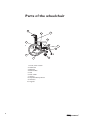
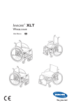
Parts of the wheelchair
4
3
9
2
6
5
10
8
1
1.
2.
3.
4.
5.
6.
7
8.
9.
10.
4
7
Frame, lower section
Seat frame
Backrest
Push handles
Seat
Rear wheel
Castors
Step tube/Anti-tip device
Armrests
Legrests
CLEMATIS®
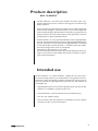
Product description
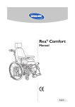
REA© CLEMATIS®
The Rea Clematis®’s seat frame, push handles and certain other components subjected to strain are made of steel. Legrests are made of high
quality aluminium.
Castor suspension and the jointed parts of the frame are made of polyamide
reinforced with fibreglass. The backrest plate is also made of polyamide
reinforced with fibreglass. Plastic details are marked for recycling. Seat and
backrest cushions are made of foam rubber and the upholstery is made of
washable plush or elastic polyurethane cloth.
The Rea Clematis® is a carer-operated wheelchair with an angle-adjustable
seat unit. The angle of the backrest unit can be adjusted independently of the
seat. The controls for the seat and backrest angle adjustment are included
on the push handles. The Rea Clematis® is available in three seat widths.
The armrest height of each chair can be adjusted.
The wheels can be pneumatic or semi solid.
The seat and backrest pads have been ergonomically designed for the user.
They are to provide as much stability and comfort as possible, as well as
good pressure distribution.
Intended use
The Rea Clematis® is a manual wheelchair, intended for users who have a
low level of activity and who sit in the wheelchair for long periods. The comprehensive comfort and stability provided by the backrest and the option of
seat unit and backrest angle adjustment provide the user with relaxed and
comfortable rest.
Clematis® is intended for operation by the carer.
!"
#
$%
of activity as well as care and maintenance.
CLEMATIS®
5
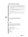
General information
Rea Clematis® is a wheelchair with many adjustment options and accessories.
To ensure that you benefit as much as possible from Rea Clematis®, and in order
to do it's options justice, the chair must be tested and adjusted by competent
personnel. We hope that you have also received instructions for using your Rea
Clematis® in everyday life.
This manual includes a description of the parts of the chair, simple adjustment
options, how to use the Rea Clematis® safely and how to transport it. The
manual must be read thoroughly before the chair is used.
Also included in this manual is a description of how the accessories are fitted and
slightly more advanced settings.
As the Rea Clematis® has many different components and accessories, the
appearance of the accessories you have for your chair may differ from those
shown.
NB!
Invacare® is only responsible for product changes carried
out by personnel who we authorise. We reserve the right
to make any changes to equipment and specifications without prior notice.
Delivery check
Check that all components match the delivery note. Any
transport damage must be reported immediately to the
transport company. Remember to keep the packaging
until the transport company has checked the goods and a
settlement has been reached.
Daily performance check
Check that the following parts are securely fitted and
operational on the wheelchair:
6
&
(
)
*
#
+
;
CLEMATIS®
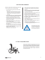
CAUTION AND WARNING
Failure to comply with instructions given may result
in personal injury and/or product damage.
chair is used:
– all parts are securely fastened to the frame.
– all handles and knobs are properly tightened.
– that all brakes and anti-tip devices function
correctly
<#
=#$
or by the footrests. Ensure that the backrest and
push bar are securely fastened to the chair.
#=
chair’s balance the inclination to tip, forwards or
backwards, also changes.
&
=
not to trap your fingers.
=
parts of your body when tilting the wheelchair’s
back and seat.
#
so much so that the inside of the armrests press
against the side of the pelvis.
)=#
moved into or out of the chair.
<# stand on the footplates when getting in
or out of the chair, because of the risk of tipping over.
We recommend that the chair should be fitted
with castor adapters when the seat is located in
its most forward position.
=
$
this may cause injury to your hands.
# *
operated brake is reduced in wet and slippery
conditions, as well as when on a slope.
( # securely attached.
>
# user is sitting in the chair.
Surfaces of the wheelchair like frame parts or
upholstery can reach temperature
> 41 degrees C if they have been exposed to the
sun during a longer period of time. .
This symbol means warning
and is used throughout the
manual for information
that needs special attention
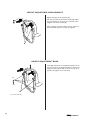
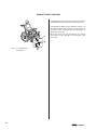
LIFTING THE WHEELCHAIR
Always lift the wheelchair by gripping the frame at the
points shown in the diagram. Never lift the wheelchair
by the removable armrests or the foot-rests. Ensure
that the backrest and push handles are securely in
place. Also read the chapter: Safety instructions/
propelling techniques.
CLEMATIS®
7
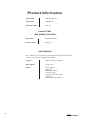
Product information
Seat width
390, 440, 490 mm
Seat depth
420-480 mm
Backrest height
550 mm
UPHOLSTERY
AND FRAME COLOURS
Upholstery
D=>!J
Frame colours
Pearl grey
ACCESSORIES
Rea™ Clematis® has a wide range of accessories and options. Some of the
accessories may not be available in all countries.
8
Castors
200 mm and 150 mm solid
Rear wheels
12", 22", 24"
Other
Trunk supports
Pelvic belt
Abduction Cushion
Arm rest spacer
Clamp for intravenous drip
Table Tray
Locking device for table tray
CLEMATIS®
Technical data – Rea Clematis®
390, 440, 490 mm
+ 20 mm with the
spacers
420-480 mm
400–450 mm*1
600-710 mm *1,2
230–340 mm *1
400–520 mm
-1°– +19°
Seat width + 210
mm
960-1120 mm*2
1120–1480 mm
-1° – +32°
Max 125 kg
Transport weight
20,5/21/21,5kg.*3
30, 32, 33,5 kg
Transportation
dimensions *4
* 1 : Measured from seat plate
* 2 : Excluding neckrest and push handles
*3: Without rear wheels, neckrest, armrests,
legrests, trunk support and seat cushion
* 4: Width 390 (h 595 x L 840 x 585 mm)
Width 440 (h 595 x L 840 x 635 mm)
Width 490 (h 595 x L 840 x 685 mm)
CLEMATIS®
9
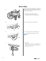
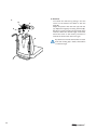
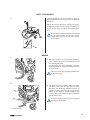
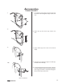
Assembly
When you receive your wheelchair, you must fit the
backrest into place and fit the neckrest, armrests and
legrests onto the chair. The assembly is simple and
does not require any tools.
1a.
1a. Fitting and securing the backrest
Unfold the backrest into an upright position.
1b.
1b. Secure the piston (A) using the pin (B).
B
A
1c. Lock the pin using the lock shackle/loop (C).
1c.
Check that the shackle/loop is securely
locked.
C
2.
10
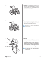
2. Armrests
The armrests are fitted onto the wheelchair by
pushing them down into their attachments on
the edge of the chair seat.
CLEMATIS®
3a.
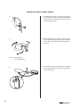
3a. Legrests
Attach the legrests by pushing the tube at the
upper part of the legrests down into the tubes
on the wheelchair. You must angle the legrests
outwards when inserting them.
3b.
3b.
Lock the legrests by turning them inwards. The
legrests are automatically locked so there is no
risk of them coming off the wheelchair.
Be careful not to trap your fingers between
frame and legrest.
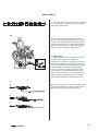
4.
C
B
A
E
D
4. Neckrest
You attach the neckrest by putting it into the
reciver on the backrest and fasten it with the
knob (B).
Adjust the position with the lever (A) and nuts
(C). Adjust the height by loosening the knob (B).
Part (E) is a memory function for the height of the
neckrest. When the desired height is achieved,
loosen the screw on the memory and lower it
towards the back. Fasten the screw again.
Pay attention to how far the neckrest is raised.
X
Z>[
#
$
is raised too high.
CLEMATIS®
11
5. Headrest
You attach the neckrest by putting it into the
reciver on the backrest and fasten it with the
knob (B).
Adjust the position with the lever (A) and nuts
(C). Adjust the height by loosening the knob (B).
Part (E) is a memory function for the height of the
neckrest. When the desired height is achieved,
loosen the screw on the memory and lower it
towards the back. Fasten the screw again.
5.
A
C
E
B
D
Pay attention to how far the headrest is raised.
X
Z>[
#
$
is raised too high.
12
CLEMATIS®
Settings
LEGRESTS
1.
Angle adjustable legrests support the legs and reduce
pressure. The legrests can be used for bandaged legs,
but not for legs in plaster casts. The legrests must
always be fitted with calf pads, footplates and heel
straps.
It is important to adjust the height and angle of the
legrests to obtain a good seating position.
1. Height adjustment
Loosen screw (A) with an Allen key. Adjust the
legrest into a suitable height and the screw is
caught by one of the recesses on the legrest tube.
Then retighten the screw.
A
Tools: 5 mm Allen key.
2.
B
2. Angle adjustment
Pull the lever (B) with one hand while supporting the legrest with your other hand. When a
suitable angle is obtained, let go of the lever and
the legrest will look into one of seven preset
positions (C).
>=
#=$
sit on the legrest. It may cause damage to the
mechanism.
C
The distance between the lowest part of
the footrest and the ground must be at least
40 mm.
CLEMATIS®
13
FOOTPLATES/CALF PADS
1. Angle-adjustable footplates
Adjust the angle and the depth by loosening the
screw (A) at the footplate attachment with a 5
mm Allen key. Adjust the footplate to the correct
position and retighten the screw.
1.
A
>=
when the screw is loose.
Tools: 5 mm Allen Key
C
D
2.
B
2. Calf pads
The calf pads can be fitted in four different depth
positions. Swing the pad forwards. Unscrew screw
(B) using an Allen key. Remove the large nut (C) on
the reverse side and place it in the other attachment hole. Move the calf pad to the new position
and secure it into place with the screw.
The height of the calf pads can easily be adjusted
Z>[
Tools: 5 mm Allen key.
ARMRESTS
1.
The armrest has an auto-lock. Press the spring (B)
before removing the armrest.
A
B
1. Armrest height
The height of the armrest can be adjusted by
loosening the screw (A) with an Allen key. Adjust
to the desired height and retighten screw.
If armrest is adjusted too low it will conflict with
the rearwheel when tilting the seat unit.
When adjusting the height, do not put your
fingers between armrest pad and side plate as
they may get trapped.
Tools: 5 mm Allen Key
14
CLEMATIS®
Seat unit
CARER-OPERATED ANGLE ADJUSTMENT
The wheelchair is equipped with carer-operated controls. You can adjust the angle of the backrest forwards
or backwards and tilt the whole seat unit including the backrest. These two functions can either be controlled
manually or electrically.
1.
1. Backrest angle adjustment
Adjust the angle of the backrest by pulling the
yellow left-hand lever (A) upwards and keeping
it there whilst you push the backrest away from
you or pull it towards you until you have obtained
the required position. Release the lever (A).
A
2.
2. Tilt adjustment
Tilt of the seat unit (seat and backrest) by pulling the green right-hand lever (B) upwards and
keeping it there whilst you tilt the seat unit to the
required position. Release the lever (B).
B
3.
Be careful that you do not trap your finger
between the seat and the armrest attachment
(picture 3).
4.
C
D
CLEMATIS®
4.Tilt lock
The tilt lock (C) allows you to set the tilting of
the seat unit and/or the angling of the backrest
to a fixed position. Tilt and/or angle the seat and
backrest to the desired position and insert the
tilt lock. The position is now set and cannot be
changed.
The tilt lock is removed by pressing the plastic peg
Z>[
lock.
15
HEIGHT ADJUSTABLE PUSH HANDLES
Adjust the height of the push handles
(90 mm) by loosening the handle wheels (B). Adjust
the push handles to one of the four positions, then
retighten the handle wheels (B).
After adjusting the push handles, always make sure
that the handle wheels are properly retighten.
B
HEIGHT ADJUSTMENT BACK
The height of the back can be adjusted variably. Loosen
the four screws (C) and adjust the back to the desired
(Z>[
possible. Re-tighten the screws firmly.
C
D
Tools: 5 mm Allen key.
16
CLEMATIS®
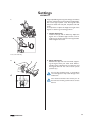
ANTI-TIP DEVICES
1.
The anti-tip devices also act as step tubes. They are
height-adjustable and can easily be set in six different
positions.
Adjust the anti-tip devices by pressing the springloaded buttons (A) and then raising or lowering the
anti-tip devices until you obtain the required position.
Ensure that both anti-tip devices are adjusted
to the same position and that the springloaded buttons pop back into place in their
new position.
A
BRAKE
1.
1. This type of brake is to be used when the wheelchair is stationary and is not intended to be used
for reducing the speed.
To apply the brake of the wheelchair, move the
lever backwards. To release the brake, move the
lever forwards.
Take care not to trap your fingers between the
brake pin and tyre.
2.
C
2. To obtain the correct braking effect, the brake
pin (B) is to press into the tyre when you apply
the brake. The brake may therefore need to be
adjusted. Loosen the screw (A) and move the
brake to the required position. Retighten the
screw. There is to be a distance of 15 mm between
pin (B) and tyre (C).
B
Incorrect setting or incorrect use of the brake
reduces the brake effect.
A
Tools: 5 mm Allen key
CLEMATIS®
17
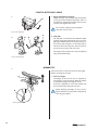
CARER-OPERATED BRAKES
1.
1. Brake when the wheelchair is moving: squeeze
both brake handles upwards and the brake will
be applied.
2.
2. Lock the brakes: squeeze the handle upwards
and move the lock catch (A) upwards. Then
release the handle.
A
3. Release the brakes: squeeze the handle upwards
3.
and the lock catch will release automatically.
Incorrect setting or use of the brakes will
reduce the braking effect.
SEAT DEPTH ADJUSTMENT
Adjust the seat depth by loosening the two screws
(A). Push or pull the seat backwards (30 mm) or
forwards (30 mm) to reach the wanted position. Retighten the screws.
A
Tools: 5 mm Allen key
18
CLEMATIS®
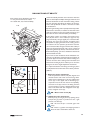
BALANCE AND STABILITY
Check the stability with the user in the chair when the
chair has been adjusted. Adjust the angle of the seat and
backrest backwards to their maximum setting. Check
the risk of tipping. Re-adjust the balance of the chair
and/or anti-tip devices to obtain a chair that is stable
in all situations.
Each setting can be adjusted in two ways:
II = easy to manoeuvre, less stable
III = stable chair, less manoeuvrability
1–2.
By moving the seating section (seat plus backrest) either
backwards or forwards, in relation to the lower frame
(and also in relation to the rear wheel and castors) you
also alter the chairs manoeuvrability and stability.
A
A
B
D
F
If the seating section is located in the forward position (III) the chair is more stable (in regard to tipping backwards), though slightly less manoeuvrable.
However, the chair also becomes somewhat more
susceptible to tipping forwards. If the seating section
is located in the rear position (II) the chair becomes
more manoeuvrable, though somewhat less stable (in
regard to tipping backwards). This can be countered
by lowering the anti-tip device, with which the chair is
fitted. Subsequently, you have a wheelchair that is both
manoeuvrable and safe.
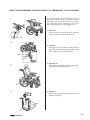
If you want to alter the balance of the wheelchair it is
necessary to adjust the two fittings (A) and position of
gas piston (B) on frame bracket.. The two fittings are
used to move the chairs seating section forwards and
backwards and the gas piston enable you to move the
fitting for the chairs angle adjustment mechanism.
3.
A
E
A II
A III
C
B
B II
B III
It is important that the two fittings and the gas piston
are adjusted and secured in the same relative positions
(table 3).
1. Adjust the upper attachment.
Take away the seat cushion, seat plate, legrests and
wheels. Put the chair with it's front facing down.
Adjust each of the fittings in this way: Slacken the
screw (C) on the upper side of the fitting by a
couple of turns, but do not unscrew it completely.
]Z>[
correct position ( II or III) is aligned with the screw
*
Z>[
Then, re-tighten screw (C).
NB – Never touch screw (E)!
2. Adjust the lower attachment.
Pull out pin (F) on the gas piston by opening clamp
and put the gas piston in position. For the right
position, see table (3).
NB – Be sure the pin is secured again with
clamp.
NB – There is a greater risk of tipping forward
when the seat is extended to the front.
CLEMATIS®
19
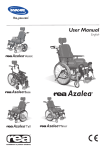
SEAT HEIGHTS
1
2
SH
20
3
45
24"
2
1
200
40
22"
1
3
150
45
12"
3
1
200
CLEMATIS®
Accessories
TRUNK SUPPORTS
1. To install the trunk support unscrew screws (A)
and remove the locking devices (B), washers and
nuts.
1.
A
B
2.
2. Fasten bar (C) with screws (A), washers and
nuts.
C
A
3.
3. ; Z>[ height.
D
4. X
Z>[
and fasten with wheel (E).
4-5.
5. To adjust the depth of the trunk support, unzip the
cover to reveal the screws. Unscrew and move the
trunk support forwards or backwards. Retighten
the screws and zip up the cover.
E
Tools: Screwdriver
CLEMATIS®
21
TRUNK SUPPORT SWING AWAY
1.
1. The attachment for the swing away trunk support
is inserted into the holder on the back and fastened
with the wheel. For instructions on how to mount
the holder see page 20.
2.
2. By loosening the nuts and bolts on the arm of the
trunk support, the angle can be adjusted. Remember to secure tightly when the desired position is
achieved.
Tools: 5 mm Allen Key
13 mm fixed spanner
3.
22
3. The trunk supports can be folded away so that they
do not obstruct the user when he or she gets into
or out of the chair.
CLEMATIS®
PELVIC BELT
1.
1. The pelvic belt is used to prevent the risk of falling or sliding out of the chair and for providing the
user with a good posture.
2-3.
2. The pelvic belt is mounted on the backrest
brackets. Thread the belt through the mounting on
the chair and then through the two plastic buckles
as shown in the picture. It is important that both
buckles are used. There is a danger the belt might
slip if the belst is treaded through only one.
3. Adjustment
Ensure that the user is sitting fully back in the
seat and that the pelvis is as upright and
symmetrical as possible - not forward on one side
or tilted back. Position the lap belt so that the hip
bones can be felt above the belt. Adjust the length
using the buckles so that there is just sufficient
room for your hand to slide between your body
and the belt. It is recommended that the clasp is
kept in a central position, i.e. make adjustments to
each side. These adjustments should be checked
and possibly changed each time the belt is used.
4.
4. If the belt has come loose at the metallic buckle
it should be threaded according to the pictures a-c.
Please make sure that the belt cannot slide.
A
B
C
CLEMATIS®
23
ABDUCTION CUSHION
The abduction cushion consists of an attachment that
is fitted into the seat frame of the chair and a pad.
C
The height and depth of the abduction cushion can
be adjusted. Place the attachment at the centre of
the front of the frame. Secure the attachment by
tightening screw (A).
Place the pad into the attachment and adjust
the height using knob (B) and the depth using
screw (C).
B
Tools: 5 mm Allen Key
Screwdriver
24
A
CLEMATIS®
CLEMATIS®
25
TRANSPORTING WHEELCHAIRS WITH USERS IN VEHICLES
Invacare has continuously worked to improve the safety in all our products for the users in different everyday
situations. This has, among other things, meant that Invacare since the mid 1990’s has let accredited research
institutes crash test several of the manual wheelchair models.We would like to inform you about the transport
of wheelchairs with seated users in vehicles that are especially adapted for this purpose. First and foremost, we
would like to point out that it is always the safest option for the user to be transported in the vehicle’s regular
seat fastened with the regular safety belt. Invacare cannot recommend transport seated in the wheelchair.But,
we are aware that there are users and situations that require vehicle transport seated in the wheelchair. In these
cases, the safety rules in this brochure must be followed in order to reduce the risk of injury in the case of an
accident.
The wheelchair has been tested according to the specifications in ISO 7176-19 “Wheeled mobility devices for use
as seats in motor vehicles”.This means that it has been through and met the requirements in a standard test of one
possible situation – full frontal collision in 48 km/h with a deceleration of 20 g and a 75 kg test dummy.The test
standard ISO 7176-19 is developed by authorities and specialists and it states a minimum demand on wheelchairs
regarding transport in vehicles. This standard is updated regularly as knowledge and experience increases.
In reality, an incident will be different from the circumstances in a test laboratory environment. For example will
speed, impact angle, configuration of the chair, user weight and deceleration probably vary. Invacare declines any
responsibility for the outcome of a possible accident where our products are involved.We have chosen to test
what we believe to be a frequently occurring configuration with common adjustments made. Configurations and
accessories that are unsuitable for seated transport in a vehicle are mentioned later on in this chapter.
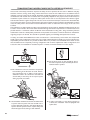
3.The tie-down points on the wheelchair where
the restraint system straps should be placed are
marked with this symbol.
1.The wheelchair and user should be transported
forward-facing in the direction of travel. All auxiliary equipment such as tables, trunk support,
abduction cushion etc should be removed and
stored safely so that they do not injure anyone
during any kind of accident.
2. The wheelchair should be secured in the vehicle with
a 4-point restraint system. The user should wear a
3-point safety belt secured in the vehicle. Both the
4-point restraint system and the 3-point safety belt
should be approved according to ISO-10542-2.
26
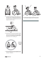
4. In order to be used as a seat during transport in
a vehicle, the wheelchair must be equipped with
a pelvic belt.
CLEMATIS®
5. The vehicle's safety belt should fit as tightly across
the user's body as possible without discomfort.
The upper part of the safety belt should fit over
the user's shoulder as illustrated. No part of the
safety belt must be twisted.
8. A headrest should always be used during transport
and it should be adjusted as shown in the picture.
6. The pelvic part of the 3-point safety belt must be
worn low across the pelvis so that the angle of
the pelvic belt is within the preferred zone (A) of
30° to 75° to the horizontal. A steeper angle is
preferred, but never exceeding 75°.
Incorrect
placement
of safety
belt
7. The 3-point safety belt must not be held away from
the user's body by parts of the wheelchair such as
armrests or wheels etc.
CLEMATIS®
27
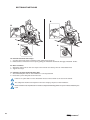
RESTRAINT METHODS
B
B
A
A
A. Frontal restraints with straps
1. Connect the frontal straps around the castor attachment. See pic A.
2. Release brakes and tension front straps by pulling the wheelchair backwards. Re-apply wheelchair brakes.
B. Rear restraints
1. Attach the snap hooks on the rear straps to the vertical rear tube by the rear wheel attachment.
2. Tighten the straps.
C. Fastening of pelvic belt and safety belt
1. Check that the pelvic belt on the wheelchair is correctly fastened.
2. Fasten the 3-point safety belt around the user.
If there is no pelvic belt in on the wheelchair the user must transfer to the seat of the vehicle.
The safety belt should not be kept from the user’s body by the parts of the wheelchair.
Never use the harness and pelvic belt in a vehicle as a safety belt. A belt designed for transport in vehicles must always be
used.
28
CLEMATIS®
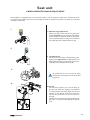
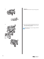
HOW TO DISSASEMBLE YOUR CLEMATIS TO TRANSPORT IT AS LUGGAGE
It is easy to prepare your Rea™ Clematis® for transport. Remove both the leg- and armrests. Fold the
wheelchair and remove the wheels (if you have a
chair with quick release wheels). You now have a
chair that will easily fit into the luggage of a car.
1.
1. Armrests
The armrest has an auto-lock. Press the spring
button (A) before removing the armrest.
A
2.
2. Legrests
The legrests are loosened by pushing the lever
(B) forwards whilst turning the legrests outwards.
You can then simply lift off the legrests.
B
3. Rearwheels
Remove the rear wheels by pushing button (C)
and pulling the wheel straight out.
3.
C
4. Neckrest
Remove the neckrest by loosening the knob (C)
and lift it straight up.
4.
C
CLEMATIS®
29
5.
5. Backrest
;=#
Z>[
D
6.
>
6. If you want to reduce the height of the chair even
more, remove the pin (G) from the lower attachment of the lower gas piston.
Be careful not to trap your fingers between
seat and frame.
30
CLEMATIS®
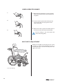
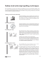
Safety instructions/propelling techniques
We recommend that you have the chair tested by the qualified person who has prescribed the wheelchair, after
he or she has made the adjustments that you request, taking your build and needs into account. We hope that you
havealso received help in learning how best to use the wheelchair. Start by practising carefully until you are familiar
with the wheelchair’s possibilities and limitations.
Moving to and from the wheelchair
Propel the wheelchair as near as possible to the seat that you
want to move to. Apply the brake. Remove the armrests or move
them upwards out of the way, and detach the legrests or swing
>=
may cause the chair to tip forwards.
Stretching and leaning
Propel the wheelchair as near as possible. When stretching and
bending, do always have full contact between the backrest and the
back otherwise the wheelchair may tip over. Stretching behind the
backrest is not recommended.
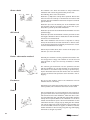
Propelling up a slope
Many experienced users manage to propel up a slope by themselves. In order not to lose control of the steering and to avoid
tipping backwards, you should always lean forwards whilst propelling up a slope. Propel the wheelchair forwards using short, quick
strokes applied to the hand rims, in order to maintain speed and
steering control.
Generally, help is needed in the case of steep slopes.
If you have to stop on a slope, it is particularly important to ensure
that you do not make any sudden or unexpected forward movements when you start moving the wheelchair forwards again. As
the wheelchair is already leaning backwards, such a movement
can cause the wheelchair to tip backwards.
Propelling down a slope
We recommend that you get the help of one or more
Clematis®ants when going down steep and wet slopes.
First check the slope to see if there are any particular risks, such
as potholes, slippery sections, etc. Never use your brake to slow
down. When you apply the brake on a downward slope, the
wheels lock and the wheelchair can suddenly pull to one side, tip
sideways or stop immediately, which can cause you to be thrown
out of the chair. Always control the speed with the hand rims.
Remember that the hand rims may become hot due to friction,
and this may cause injury to your hands. Try to propel down the
slope in a straight line as much as possible. Never change direction when propelling down a slope. Never propel up or down a
slope crosswise.
CLEMATIS®
31
Onto a kerb
This method is for when the assistant is always behind the
wheelchair and creates the greatest safety for the user.
The following advice is for the assistant:
Illustration 1) Adjust the anti-tip device upwards. Ensure that
the user’s feet rest securely on the footrests and cannot slide
off. Then lean the wheelchair backwards and push it forwards
against the kerb.
Illustration 2) Lower the frontal part of the wheelchair onto
the pavement and place yourself as close to the chair as possible, before you lift up the whole wheelchair.
Off a kerb
Illustration 3) Lean forward and lift/roll the wheelchair over the
pavement edge.
Illustration 4) Lower the wheelchair onto the pavement so that
the weight is divided on all four wheels. Ensure that the wheelchair does not roll backwards.
NB! If the wheelchair does not have a step tube or anti-tip
device, tilt the backrest and seat backwards to make it easier
to tip the chair backwards and thereby manoeuvre the castors
over the obstacle/kerb more easily.
Follow the procedure above, but in reverse order (step 4, 3, 2
and then 1) to move off a kerb.
Kerbs - alternative method
Generally this method is used by experienced assistants who
are stronger than average. The method can be also be used
when the kerb or step is low and only constitutes a minimal
obstacle.
The assistant goes backwards onto the pavement and then
pulls the wheelchair up onto the pavement. It is important for
the assistant to use his/her body correctly to prevent injury.
Tip the wheelchair backwards and roll the chair over the kerb
onto the pavement. Take particular care if the kerb is wet or
slippery.
Escalators
> ;
whether there is a lift nearby.
We advise you to avoid going up/down stairs in your wheelchair
where possible, and to choose an alternative route instead.
Stairs
32
We recommend that you receive help from two assistants to
get up and down stairs. One assistant goes in front of the chair
and hold the frame of the wheelchair, whilst the other assistant goes behind the chair and holds the push handles. Fold the
anti-tip device upwards. Balance the wheelchair on the drive
wheels until the balance point is found. The wheelchair is then
rolled down the stairs, step by step, by letting the drive wheels
roll over the edge of each step. Assistants must remember not
to hold removable armrests or legrests. In addition, assistants
should remember to lift correctly, using their legs and keeping
their backs as straight as possible.
CLEMATIS®
Guarantee
We provide a 2-year guarantee from the delivery date. The guarantee is valid from the day of
delivery to the paying customer. Wear of parts is not included in the guarantee, for example
=$=$$
$>$==
#
$>$=#
model plate, are excluded.
Accidents/Near-accidents
Please inform your Invacare sales company (phone number is on the back cover) of any accidents/
near-accidents that were caused by this wheelchair and that have led to/could have led to personal injury. The relevant authority in your country must also be notified.
Testing
Rea™ Clematis® has been tested and approved by CERAH and is CE-marked according to the
{
>#
>
#
Maintenance
It is easy to keep your Rea™ Clematis® wheelchair clean and in good condition.
Cleaning
Wipe metal sections and the upholstery regularly with a damp cloth. A mild detergent may
be used. If necessary, the upholstery can be washed at 40ºC. Ordinary washing powder/liquid
can be used.
Washing and Disinfection
1. Remove all loose and removable covers and wash these in a washing machine following the
washing instructions for each article.
2. Spray the wheelchair with detergent, for example a car-cleaning agent with wax, and leave on
to work.
3. Rinse the wheelchair with a high-pressure cleaning or ordinary jet of water depending on how
=
>
X
washed in a machine the water must not be hotter than 60 degrees.
4. Spray the chair with alcohol for disinfection.
5. Leave the chair to dry in a drying cabinet. Remove parts where water has collected for example
in end tubes, ferrules etc. If the chair has been washed in a machine, blow-drying with compressed air is recommended.
Wheels and tyres
Wheel axles are to be wiped clean and lubricated with a drop of oil.
Pneumatic tyres have valves similar to those on a car tyre, and the tyres
can be pumped up using the same type of pump used for cars. The recommended air pressure
for drive wheels is:
Standard tyres:
3.5 bar 50 psi
Low profile tyres
7.0 bar 90 psi
CLEMATIS®
33
Technical servicing
Only original parts or those approved and fulfilling Invacare’s specifications may be used.
All technical servicing is to be carried out by an authorised wheelchair technician or by Invacare’s
service department. The wheelchair should be checked by authorised wheelchair technicians or
Invacare's service department once a year. The address and telephone number are on the back
cover of the manual.
Check all parts of the wheelchair once a week. If you discover damage, please contact Invacare
immediately. The address and telephone number are on the back cover of this manual.
Service life
We estimate that Rea™ Clematis® has a service life span of five years. It is difficult to state the
exact length of the service life of our products, and the length stated is an estimated average life span
based on normal use. The life span may be considerably longer if the wheelchair is used to a limited
extent, and if it is used with care, maintained and handled properly. The life span may be shorter if
the wheelchair is subjected to extreme use.
Recycling
The wheelchair Rea™ Clematis® can be divided into the following main components:
+
]=
&$=
+
Chassis
The chassis is produced in steel and is fully recyclable. Recycling of steel requires only 20-25% of the
energy compared to new produced steel.
Clematis® has two gas pistons and they contain oil and must be disposed according to national
requirements
Plastic parts
The plastic parts in the chairs are produced of "Thermoplastic" and are marked with recycling symbols
(where it is possible due to part size). The main plastic material is polyamide. This material can be
recycled or burned in approved facilities.
Upholstery
Upholstery is produced of polyester fibres, PUR or PVC. The efficient way to recycle the parts is to
burn them in approved facilities.
Wheels, tyres and tubes
$
$$
recycled according to above.
==
#
Packing
All Invacare Rea AB packing material is developed to fit the products in an optimal way to reduce
unnecessary material waste. All boxes are recyclable.
Contact your local recycling agent to otain the correct information how to handle the above mentioned materials.
SURFACE TREATMENT
Lacquered surfaces are lacquered with polyester. Some steel parts are zinc-plated. Not lacquered
aluminium parts are anodised. Visible wooden parts are lacquered.
34
CLEMATIS®
CLEMATIS®
35
Produsent
Invacare Rea AB
Växjövägen 303 S-343 71 DIÖ SWEDEN
Danmark:
Invacare A/S, Sdr. Ringvej 37, DK-2605 Brøndby
Tel: (45) (0)36 90 00 00, Fax: (45) (0)36 90 00 01
[email protected]
Deutschland:
Invacare Aquatec GmbH, Alemannenstraße 10, D-88316 Isny
Tel: (49) (0)75 62 7 00 0, Fax: (49) (0)75 62 7 00 66
[email protected]
Ulrich Alber GmbH, Vor dem Weissen Stein 21,
D-72461 Albstadt-Tailfingen
Tel: (49) (0)7432 2006 0, Fax: (49) (0)7432 2006 299
[email protected]
European Distributor Organisation:
Invacare, Kleiststraße 49, D-32457 Porta Westfalica
Tel: (49) (0)57 31 754 540, Fax: (49) (0)57 31 754 541
[email protected]
España:
Invacare SA, c/Areny s/n, Polígon Industrial de Celrà, E-17460
Celrà (Girona)
Tel: (34) (0)972 49 32 00, Fax: (34) (0)972 49 32 20
[email protected]
France:
Invacare Poirier SAS, Route de St Roch, F-37230 Fondettes
Tel: (33) (0)2 47 62 64 66, Fax: (33) (0)2 47 42 12 24
[email protected]
Ireland:
Invacare Ireland Ltd, Unit 5 Seatown Business Campus, Seatown Road, Swords, County Dublin - Ireland
Tel: (353) 1 810 7084, Fax: (353) 1 810 7085
[email protected]
Italia:
Invacare Mecc San s.r.l., Via dei Pini 62, I-36016 Thiene (VI)
Tel: (39) 0445 38 00 59, Fax: (39) 0445 38 00 34
[email protected]
Nederland:
Invacare BV, Celsiusstraat 46, NL-6716 BZ Ede
Tel: (31) (0)318 695 757, Fax: (31) (0)318 695 758
[email protected]
[email protected]
Norge:
Invacare AS, Grensesvingen 9, Postboks 6230, Etterstad,
N-0603 Oslo
Tel: (47) (0)22 57 95 00, Fax: (47) (0)22 57 95 01
[email protected]
[email protected]
Österreich:
Invacare Austria GmbH, Herzog Odilostrasse 101, A-5310
Mondsee
Tel: (43) 6232 5535 0, Fax: (43) 6232 5535 4
[email protected]
Portugal:
Invacare Lda, Rua Estrada Velha, 949, P-4465-784 Leça do
Balio
Tel: (351) (0)225 1059 46/47, Fax: (351) (0)225 1057 39
[email protected]
Sverige & Suomi:
Invacare AB, Fagerstagatan 9, S-163 91 Spånga
Tel: (46) (0)8 761 70 90, Fax: (46) (0)8 761 81 08
[email protected]
[email protected]
Switzerland:
Invacare AG, Benkenstrasse 260, CH-4108 Witterswil
Tel: (41) (0)61 487 70 80, Fax: (41) (0)61 487 70 81
[email protected]
United Kingdom:
Invacare Limited, Pencoed Technology Park, Pencoed,
Bridgend CF35 5HZ
Switchboard Tel: (44) (0)1656 776200,
Fax: (44) (0)1656 776201
Customer services Tel: (44) (0)1656 776222,
Fax: (44) (0)1656 776220
[email protected]
Australia
Invacare Australia Pty. 1 Lenton Place, North Rocks,
NSW 2151
Tel. (61) (0) 2 8839 5300 Fax. (61) (0) 2 8839 5313
[email protected]
New Zealand
Invacare New Zealand, 4 Westfield Place, Mt. Wellington,
Auckland 1644
Tel. (64) (0) 9 917 3939
Fax. (64) (0) 9 917 395Z
[email protected]
Art. No. 1439960-7 2013-03
Sales Units:
Belgium & Luxemburg:
Invacare nv, Autobaan 22, B-8210 Loppem
Tel: (32) (0)50 83 10 10, Fax: (32) (0)50 83 10 11
[email protected]