1
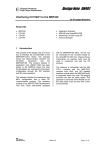
Johnson C8000
SERVICE MANUAL
1
TABLE OF CONTENTS
SECTION 1: MAINTENANCE PROCEDURE…………….…...3
1. Preventive maintenance schedule……………………..……..…..4
2. Cleaning the grooves………………………………………..........5
SECTION 2: WIRING DIAGRAM INSTRUCTION…...........…6
1. C8000(CB66) Electrical block diagram…………………………7
2. Johnson C8000 wiring diagramction…………………………….8
3. Console cable wiring diagram ………………….………………..9
4. Pulse sensor wire wiring diagram…………………..……...….….9
5. Generator Wire wiring diagram…………………………………..10
SECTION 3: CONSOLE ENGINEERING MODE GUIDE…….11
1. How to enter into the engineering mode?...................................12-15
SECTION 4: TROUBLESHLOOTING…………………………..16
1.
No display on the console or the display is dim……………….17
2.
All or some of the function keys do not respond…………...….18
3.
No resistance change or too hard for pedaling…………………19
4.
Feel slipping while pedaling……………………………………20
5.
Knocking or creaking noises……………………………………20
6.
Heart-Rate-Control function does not work…………………….21
SECTION 5: SOFTWARE UPGRADE PROCEDURE…………..22
1. Johnson C8000 bike software upgrade ........................................23-28
2
SECTION 1
MAINTENANCE PROCEDURE
3
PREVENTIVE MAINTENANCE SCHEDULE
BIKE
Item
Daily
Weekly
Monthly
Quarterly
Console Mounting
Bolts
Annual
Inspect
Frame / All Cover
Clean
Display Console
Clean
Handlebar
Clean
Inspect
Inspect
Inspect
Handrail &
Handlebar
Belt Grooves
Biannual
Inspect
Inspect
V Belt
Inspect /
Clean
Air Shock
Lubricate
4
CLEANING THE GROOVES
Caution:
If there is any dust in the grooves of the Poly-V belts and pulleys, noises
will be generated during operation.
Frequency: Every 6 months.
Procedure:
1.Remove the Poly-V belts and check
the grooves of the belt for dirt or dust
and clean it if any.
2.Check the grooves in the pulley for
dirt or dust and clean it if any.
3.Check the grooves in the roller pulley
for dirt or dust and clean it if any
5
SECTION 2
WIRING DIAGRAM INSTRUCTION
6
C8000(CB66) Electrical block diagram
7
Johnson C8000 WIRING DIAGRAM INSTRUCTION
8
P01 : Console cable
P02 : Pulse sensor wire
9
P03 : Generator Wire
10
SECTION 3
CONSOLE ENGINEERING MODE GUIDE
11
How to enter into the engineering mode?
1.To enter the Manager’s Custom Mode,
press and hold down the "LEVEL UP
and DOWN arrow keys“ continue to
hold down these two keys until the
INSTRUCTION CENTER displays
show the “MANAGER MENU”.
1.
To scroll through the list of Manager’s Custom Mode, use the “LEFT / RIGHT
ARROW keys”, or "LEVEL ARROW keys". The INSTRUCTION CENTER
will display, in turn, each of custom settings.
2. To select a custom mode, press the SELECT key to enter.
3.
To change the value of the setting, use the “LEFT / RIGHT ARROW keys”,
or "LEVEL ARROW keys".
4.
To confirm and save the value of the setting, press the QUICK START key.
“SETTING SAVED” will appear in the INSTRUCTION CENTER.
To exit the setting without saving, press the RESET key within 5 seconds, or if
there is no key pressed, the system will resume automatically.
12
13
14
15
SECTION 4
TROUBLESHOOTINGS
16
No display on the console or the display is dim
Possible causes:
1. Console is damaged or the console cable is not connected properly.
2. Poor connection to all the terminals on the control board.
3. Controller is damaged.
4. Generator is damaged.
Fix:
1. First, unplug the console cable and use a multi-meter to check if
the voltage between the 1(Vcc) and 7(Ground) pin of the console
cable is greater than 12.
(If it is, replace the console and check again.
2. Open the side covers then check if all the wire harnesses are
connected properly to the terminals of the control board
3. Unplug the generator cable from the Controller and pedal the
machine to check if the voltage is variable.
If it is, replace the Controller with a new one.
If it is not, replace the generator with a new one.
17
All or some of the function keys do not respond
Possible causes:
1. Keypad connecting plug has been not fit-in properly.
2. Keypad is damaged.
3. Upper board is damaged.
Fix:
1. Remove the console cover, and then check if keypad cable is
connected properly to the upper board.
If it has not been connected well, reconnect it to the terminal and
check again.
2. Keypad or upper board is damaged.
Replace the console.
18
No resistance change or too hard for pedaling
Possible causes:
1. Console is damaged or the console cable is not connected properly.
2. Console cable is damaged.
3. Generator is damaged.
4. Controller is damaged.
Fix:
1. Remove the console and check if the console cable has been connected
properly.
2. Remove the side covers and check if the console cable is connected well
to the controller properly.
3. Please make use of tools to confirm “Generator” have
conduct(10~15Ω).
If it is damage, Please replace “Generator”
If it is well, Please replace control board
19
Feel slipping while pedaling
Possible causes:
1. Belt tension is not enough.
2. One way bearing is damaged.
Fix:
1. Remove all of the cover.
2. Pedaling and check if the belt tension is correctly.
3. One way bearing is damaged. Replace it with a new
one. (instruction see below).
Knocking or creaking noises
Possible causes:
1. Pedal is on crank arm too loose
2. Crank or axle is wear out
3. Belt tension is too loose or poly v belt is too dirty
Fix:
1. Re-tighten it.
2. Replace it with a new one
3. Re-adjust the belt tension and clean the poly v belt
20
Heart-Rate-Control function does not work
Possible causes:
1. Bike does not contact with user's chest very well.
2. Bike (Polar-belt) is at low battery status.
3. Bike (Polar-belt) is damaged.
4. Heart-rate-control board is damaged.
5. PCB is damaged.
Fix:
1. Center the bike on your chest below the pectoral muscle(breast) as
shown, then check again.
2. Remove the battery cover of the bike. Replace a new battery and
check again.
Actually, as moisture may activate the transmitter, please dry
transmitter after use.
3. Transmitter is damaged. Replace the Transmitter.
4. Heart-rate-control board is damaged. Replace the HR-control board.
5. PCB is damaged. Replace the PCB.
21
SECTION 5
SOFTWARE UPGRADE PROCEDURE
22
Johnson C7000 BIKE SOFTWARE UPGRADE SOP
A. Service Tools & Accessories:
1.
2.
3.
MSP-FET430 (Please refer the bulletin NB-0506002)
Parts NO: MT00L-039
Software
23
1
2
3
6
4
5
Please refer the above photo to set the parameter.
Press the File Name Find out the software version file in the computer
and then actuate/open the file.
Note
When upgrade LCB the device type (3) has to select MSP430 F135
When upgrade PCB the device type (3) has to select MSP430 F149
24
Computer
Install the MSP430 Tools
25
Press the Load Image, Installation software to MSP430
Tools.
26
MSP430
Installing the MSP430 cable to console.
27
1. Press the MSP430 “START” key, the “MODE” light will to
glitter about 10 sec, If installing pass, the OK LET light.
2. Drive the machine to provide power for console and then
enter into the engineering mode to confirm if the software had
been installed/upgraded
28