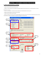
1
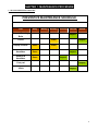
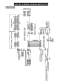
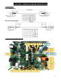
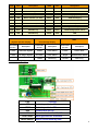
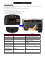
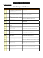
Vision Fitness S70-02 (EP78B) Service Manual
TABLE OF CONTENTS
CHAPTER 1: MAINTENANCE PROCEDURE
1.1
Preventive Maintenance Schedule……………..……..……………………………………….……..4
1.2
Cleaning the Grooves………………………………………...........................................................5
CHAPTER 2: WIRING DIAGRAM INSTRUCTION
2.2
Electrical Installation.……………………………………………………………………….…………..6
2.2
Electrical Diagram………………………………………………………………………………………7
2.3
Wiring Diagram………….………………………………………………………………………………8
2.4
LCB Wiring Diagram……………………………………………………………………………………8
2.5
Console Wiring Diagram……………………………………………………………………………….9
CHAPTER 3: ENGINEERING MODE
3.1
Using Engineering Mode………………….…………………………………………………………...10
3.2
Using Engineering Mode – Continued………………………………………………………………..11
CHAPTER 4: TROUBLESHOOTING
4.1
Console Error Codes…………………………………………………………………………………….12
4.2
Troubleshooting – No Display on the Console or the Display is Dim……………………….……...13
4.3
Troubleshooting – No RPM is Displayed During the Exercise………………………………………14
4.4
Troubleshooting – All or Some of the Function Keys do not Respond…..…………………………15
4.5
Troubleshooting – High or No Resistance……………………………………………………………. 16
4.6
Troubleshooting – Pedals Slipping……………………………………………………………………..17
4.7
Troubleshooting – Knocking or Creaking Noise………………………………………………………17
4.8
Troubleshooting – Heart Rate Function Does Not Work or is Reading Incorrectly……………….18
CHAPTER 5: PART REPLACEMENT GUIDE
5.1
Shroud Replacement…………….…………....................................................................................19
5.2
Lower Control Board Replacement...……………….......................................................................21
5.3
Power Resistor Replacement………………...................................................................................22
5.4
Generator Replacement………………...........................................................................................23
5.5
Generator Belt Replacement…………………................................................................................25
5.6
Drive Axle Replacement……………..............................................................................................27
5.7
Pulley Axle Set Replacement……….………..................................................................................28
5.8
Drive Axle Set Replacement..........................................................................................................29
5.9
Crank Replacement…………….....................................................................................................33
5.10 Console Replacement………………..............................................................................................34
5.11 Incline Motor Replacement…………………...................................................................................35
5.12 Dual Action Handlebar Replacement……………………................................................................37
2
CHAPTER 5: PART REPLACEMENT GUIDE
5.13 Console Mast Replacement……………………………................................................................38
5.14 Foot Pedal Replacement……………….......................................................................................39
5.15 Pedal Arm Replacement……………...........................................................................................40
5.16 Link Arm Replacement………….................................................................................................42
5.17 Incline Arm Replacement………………………...........................................................................43
5.18 Swing Arm Replacement…………..............................................................................................44
5.19 Vertical Stabilizer Arm Replacement..........................................................................................45
5.20 Incline Arm Replacement............................................................................................................46
5.21 Hear Rate Grip Replacement……………….................................................................................47
5.22 Testing the Elliptical………………...............................................................................................48
CHAPTER 6: SOFTWARE UPGRADE PROCEDURE
6.1
Software Upgrade Instructions……………..…............................................................................49
3
CHAPTER 1: MAINTENANCE PROCEDURE
1.1 Preventive Maintenance Schedule
PREVENTIVE MAINTENANCE SCHEDULE
Item
Daily
Weekly
Monthly
Quarterly Biannual
Console Mounting
Bolts
Inspect
Frame
Clean
Display Console
Clean
Handlebar
Clean
Handrail &
Handlebar
Clean
Inspect
Clean
Inspect
Inspect
Foot pad
V Belt
Annual
Inspect
Inspect
4
CHAPTER 1: MAINTENANCE PROCEDURE
1.2 Cleaning the Grooves
If there is any dust in the grooves of the Poly-V belts and pulleys, noises will be generated during operation.
Frequency: Every 3 to 4 months.
[Procedure]:
1. Remove the Poly-V belts (490-J8) and check the grooves of the belt for dirt or dust and clean if any is present.
2. Check the grooves in the pulley for dirt or dust and clean if any is present.
3. Check the grooves in the roller pulley for dirt or dust and clean if any is present.
5
CHAPTER 2: WIRING DIAGRAM INSTRUCTION
2.1 Electrical Installation
6
CHAPTER 2: WIRING DIAGRAM INSTRUCTION
2.2 Electrical Diagram
7
CHAPTER 2: WIRING DIAGRAM INSTRUCTION
2.3 Wiring Diagram
P06- CONSOLE WIRE
P08- INCLINE MOTOR WIRE
2.4 Lower Control Board Wiring Diagram
8
LED#
Color
LED1
Red
LED2
Red
LED3
Descriptions
LED#
Color
Descriptions
LED10
Green
INCLINE 1 down
AC Plug IN
LED11
Red
INCLINE 2 down
Green
Vcc(5V)
LED12
Yellow
Charging (PWM)
LED4
Red
Status indicator (ref. Note)
LED13
Red
40HR-discharging
LED5
Red
Status indicator (ref. Note)
LED14
Green
12V/6A-main power
LED6
Red
Status indicator (ref. Note)
LED15
Green
Console power
LED7
Yellow
PWM-Resistance
LED16
Red
E_RPM-Extra power
LED8
Green
INCLINE 1 up
LED17
Green
15V/8A-Charge power source
LED9
Red
INCLINE 2 up
LED18
Red
FAN
Generator
RPM
LED 4 :
LED 5 :
(System operation display)
Error Message Display
Pulse times
per sec.
Description
Pulse times
per sec.
Description
LED 6
Pulse times
per sec.
Description
2 times
Self-Power System
2 times
Class B Error
2 times
Class C Error
1 times
AC Plug-in System
0.5 times
Class A Error
bright
NO Resistance Offset
1 times
Burn-in (1)
0.5 time
Burn-in (1)
2.5 Console Wiring Diagram
Port
JQK
JQK1
JHD
JAI
JHG1/JHG2
Select switch
Function
Quick key cable for S70
Quick key cable for R70
Console wire for S70
Console wire for S60, U70, R70
Hand grip cable for all models
Select current model by hand
9
CHAPTER 3: ENGINEERING MODE
3.1 Using Engineering Mode
1. Press & Hold both UP and DOWN RESISTANCE keys at the same time for 3-5 second to enter Engineering Mode as shown in Figure A. The display
will show “P1 MAX TIME” as shown in Figure B.
2. To scroll through the list of options in Engineering Mode, use the UP and DOWN RESISTANCE keys.
3. Press the ENTER key to see the value of the function.
4. To change the value of the setting, use the UP and DOWN RESISTANCE keys.
5. To confirm and save the value of the setting, press the ENTER key.
6. Press and hold the START key for 3-5 seconds to return to normal operation.
FIGURE A
KEY NAME
POSITION
FIGURE B
FUNCTION
UP
SELECT FUNCTION OR ADJUST VALUE
DOWN
SELECT FUNCTION OR ADJUST VALUE
ENTER
ENTER THE FUNCTION ITEM
HOLD “ENTER” KEY 3’S
TO SAVE THE CHANGE
HOLD “ START” KEY 3’S
TO BACK OUT OF SUB MENU OR EXIT TO
MAIN MENU
HOLD RESISTANCE
TO ENTER ENGINEERING MODE
“ UP&DOWN” KEY 3’S
HOLD RESISTANCE
“ UP&DOWN” KEY 3’S
HOLD RESISTANCE
ON THE
SYSTEM PARAMETER
“VERSION”
RESET
ON THE “AC TIME”,OR “AC DIST” TO CLEAR THE AC TIME OR AC DISTANCE
“ UP&DOWN” KEY 3’S
HOLD ENTER KEY 3'S
ON “INCLINE CAL”
INCLINE CALIBRATION
10
CHAPTER 3: ENGINEERING MODE
3.2 Using Engineering Mode – Continued
CUSTOM
SETTING
DEFAULT
MINIMUM
MAXIMUM
MAX TIME
99 min
5 min
99 min
Set a maximum workout time
USER TIME
60 min
5 min
99 min
Set a default workout time
DF AGE
40
10
100
80kg
40kg
182kg
/150lbs
/80lbs
/400lbs
DF LEVEL
1
1
20
DF GENDER
MALE
FEMALE
MALE
Set a default gender for all programs
UNIT
MILE
KM
MILE
Set the unit to miles or kilometers
MACHINE
EP
-
-
AC TIME
0
0
999999 hr
AC Distance
0
0
-
-
-
Used by service technicians to test LED displays
-
-
-
For factory setting only
KEYPAD TEST
-
-
-
For keypad test
VERSION
-
-
-
Display Current software version
LANGUAGE
English
DF WEIGHT
DISPLAY
TEST
HOMING
Set a default user weight for all programs
Set a default resistance level for all programs
Set machine to elliptical mode
Accumulate time
The native language prompts in the instruction center
INCLINE CAL
INCLINE
Set a default age for all programs
999999 mile Accumulate distance
TEST
MACHINE
DESCRIPTION
Incline calibration
ON
OFF
ON
On/off incline automation reset to zero position
11
CHAPTER 4: TROUBLESHOOTING
4.1 Console Error Codes
Error Messages on the Console
Code
Class
0x0140
B
Description
Solution
When UCB implements an Incline command, Incline
Replace incline motor
has no action for 3 seconds.
When the incline position does not match the noted
0x0142
B
position and the difference is not reduced to 3% for 3 Auto calibration or replace incline motor
seconds.
When UCB implements a command, LCB has not
0x0441
B
Check the console cable connection, replace the LCB.
received this command.
Incline calibration error. When calibration time is too
0x01A1
C
Replace Incline motor
long or calibration distance is too short
Incline has short circuited (7A) or the current is over 5A
0x01A7
C
Replace Incline motor
for 1 second.
Power resistor is short circuited (over 4A), or the current
0x01AC
C
Check the connection of power resistor or replace power resistor
is over 3.7A for 1 second.
0x02AB
C
Machine Type Error
Set the Machine Type to the correct type of LCB
0x02B3
C
Resistance Type Error
Set the Machine Type to the correct type of LCB
0x04A0
C
The LCB has no message returned to the UCB for over
Check the console cable connections, replace the LCB / UCB as needed.
3 seconds.
0x0201
A
LCB Battery Low Voltage
Check battery recharge function or replace new battery
0x0248
B
Battery disconnection or fail.
Check the connection of battery or replace new battery
0x01A0
C
Incline Motor no connection
Check the connection of incline motor or replace incline motor
12
CHAPTER 4: TROUBLESHOOTING
4.2 Troubleshooting – No Display on the Console or the Display is Dim
NO DISPLAY ON THE CONSOLE OR THE DISPLAY IS DIM
POSSIBLE CAUSES:
1. The console is damaged or the console cable is not connected properly.
2. Poor connection to all the terminals on the lower control board.
3. The lower control board is damaged.
4. The generator is damaged.
SOLUTION:
1. Check the connection of the console cable at the UCB.
2. Remove the console cable from the JHD socket on the console. Pedal the machine and set your multi-meter to DC voltage and place both
terminals on pins 1 & 7 of the console cable. There should be a reading of more than 5.5VDC (Figure A).
- If voltage is more than 5.5VDC, replace the console.
- If voltage is less than 5.5VDC, or the new console does not resolve the issue, replace the console cable.
3. Open the shrouds then check if all the wire harnesses are connected properly to the terminals of the LCB.
4. Unplug the generator cable from the control board, pedal the machine and set your multi-meter to AC voltage and place both terminals on pins 1 &
2, pins 2 & 3, and pins 3 & 1 of the console cable to check if the voltage is variable (Figure B).
- If the voltage reading shown is variable (varies based on RPM), replace the LCB.
- If the voltage reading shown is not variable, replace the generator.
FIGURE A
FIGURE B
13
CHAPTER 4: TROUBLESHOOTING
4.3 Troubleshooting – No RPM is Displayed During the Exercise
NO RPM IS DISPLAYED DURING THE EXERCISE
POSSIBLE CAUSES:
1. The console is damaged or the console cable is not connected properly.
2. Poor connection to all the terminals on the lower control board.
3. The lower control board is damaged.
4. The generator is damaged.
SOLUTION:
1. Check the connection of the console cable at the UCB.
2. Remove the console cable from the J5 socket on the console. Pedal the machine and set your multi-meter to resistance and place a terminal on pin
3 of the console cable at both the LCB and UCB. There should be a resistance (ohm) reading (Figures A & B).
- If a resistance reading is shown, replace the console.
- If the there is no resistance reading, or a new console does not resolve the issue, replace the console cable.
3. Open the shrouds and check if all the wire harnesses are connected properly to the terminals of the LCB.
4. Unplug the generator cable from the LCB and pedal the machine to check if the voltage is variable.
- If a variable voltage reading is shown (varies based on RPM), replace the LCB.
- If the voltage reading shown is not variable, replace the generator.
FIGURE A
FIGURE B
14
CHAPTER 4: TROUBLESHOOTING
4.4 Troubleshooting – All or Some of the Function Keys Do Not Respond
ALL OR SOME OF THE FUNCTION KEYS DO NOT RESPOND
POSSIBLE CAUSES:
1) The keypad connection ribbon cable has not been plugged in correctly.
2) The keypad is damaged.
3) The UCB is damaged.
SOLUTION:
1) Check the connections of the keypad at the UCB.
a. Remove the console from the console mast.
b. Remove the 4 screws holding the back of the console to the front (Figure A).
c. Inspect the keypad ribbon cable connection at the UCB (Figure B).
d. Even if the keypad ribbon cable appears to be connected correctly, unplug and reseat the cable, then retest.
2) Replace the affected keypad.
3) Replace the UCB.
FIGURE A
FIGURE B
15
CHAPTER 4: TROUBLESHOOTING
4.5 Troubleshooting – High or No Resistance
HIGH OR NO RESISTANCE
POSSIBLE CAUSES:
1) The console is damaged or the console cable is not connected properly.
2) The console cable is damaged.
3) The power resistor is damaged.
4) The LCB is damaged.
5) The generator is damaged.
SOLUTION:
1) Check the console cable connections at the UCB and LCB.
2) Remove the rear shrouds and check if the console cable is connected properly to the LCB.
3) Set your multi-meter to resistance (ohms) and place both terminals on the power resistor wires .Check the power resistor wires for resistance (Figure
A).
-If the power resistor wire does not have resistance, replace the power resistor.
4) Unplug the generator cable from the LCB.
Pedal the machine and set your multi-meter to AC voltage and place both terminals on pins 1 & 2, pins 2 &
3, and pins 3 & 1 of the console cable to check if the voltage is variable (Figure B).
- If a variable voltage reading is shown (varies based on RPM), replace the LCB.
- If the voltage reading shown is not variable, replace the generator.
FIGURE A
FIGURE B
16
CHAPTER 4: TROUBLESHOOTING
4.6 Troubleshooting – Pedals Slipping
PEDALS SLIPPING
POSSIBLE CAUSES:
1) The belt tension is not high enough.
2) The one way bearing is damaged.
SOLUTION:
1) Remove the shrouds and check the belt tension.
a. Tighten the drive belt tension if needed by moving the spring tension clip to another hole.
b. The generator belt should be tightened to 85 ft / lbs.
2) If the belts are tensioned correctly, the one way bearing is damaged, replace the drive assembly.
4.7 TROUBLESHOOTING – KNOCKING OR CREAKING NOISE
KNOCKING OR CREAKING NOISE
POSSIBLE CAUSES:
1) There is hardware that is not tight or is missing.
2) The noise is related to the incline.
3) The belt tension is not high enough, or the belts are too dirty.
SOLUTION:
1) Inspect the unit and check for any loose hardware. Pay special attention to areas where arms meet. Tighten hardware where found.
2) If the noise is present only during incline, check to make sure the Teflon washers are installed at the incline motor connection point (Figure A).
a. Lubricate the gear shaft of the incline motor with grease (Vision recommends Super Lube brand Lithium Grease where available).
3) Remove the covers and check the belt tension.
a. Tighten the drive belt tension if needed by moving the spring tension clip to another hole (see Section 5.17). It should be set to 180 ft / lbs of
tension.
b. The generator belt should be tightened to 90 ft / lbs.
4) Clean the belts. If they are worn or will not clean, replace the belts.
FIGURE A
17
CHAPTER 4: TROUBLESHOOTING
4.8 Troubleshooting – Heart Rate Function Does Not Work or is Reading Incorrectly
HEART RATE FUNCTION DOES NOT WORK OR IS READING INCORRECTLY
POSSIBLE CAUSES:
1) The heart rate grips are not connected properly or are defective.
2) The heart rate grip wiring is damaged or not connected correctly.
3) The HR board is damaged.
4) The UCB is damaged.
SOLUTION:
1) With a multi-meter set for DC voltage, place one terminal on each of the HR grip plates. The HR grip should give a voltage reading of between 0.5 and
2.0VDC.
a. If the voltage is not between 0.5 and 2.0VDC, remove the 3 screws holding the HR grip together and check the connection of the HR grip wiring.
2) Check continuity of the HR grip wiring.
a. Place one terminal of a multi-meter set for resistance on the HR grip wiring at the HR grip, and the other terminal on the HR grip wiring at the
console. An ohm reading of around 1 should be expected. If the reading is higher than 1, replace the HR grip wiring.
3) Remove the console. Remove the 6 screws holding the front of the console to the rear. Check the connection of the HR board wiring to the UCB.
a. If all the wiring is intact and has good contact, replace the HR board.
4) If the HR board, HR grips, and HR grip wiring do not solve the issue, replace the UCB.
18
CHAPTER 5: PART REPLACEMENT GUIDE
5.1 Shroud Replacement
1) Remove the link arm plastic caps (Figures A).
2) Detach the link arm (Figure B).
FIGURE A
FIGURE B
3) Remove the 6 screws that hold the back cover to the shrouds and remove the back cover (Figure C).
FIGURE C
FIGURE D
19
CHAPTER 5: PART REPLACEMENT GUIDE
5.1 Shroud Replacement – Continued
4) Remove the 5 screws on right side holding the shrouds in place (Figures E).
5) Remove the 5 screws on left side holding the shrouds in place (Figures F).
FIGURE E
FIGURE F
6) Remove the shrouds for frame access (Figure G).
FIGURE G
7) Reverse Steps 1- 6 to install new shrouds.
20
CHAPTER 5: PART REPLACEMENT GUIDE
5.2 Lower Control Board Replacement
1) Remove both shrouds from the machine as outlined in Section 5.1.
2) Remove 3 screws from the LCB cover (Figure A).
FIGURE A
3) Disconnect the cables and remove the 2 screws holding the LCB to the frame (Figure B).
FIGURE B
4) Reverse Steps 1- 3 to install a new LCB.
5) Test the Elliptical for function as outlined in Section 5.22.
21
CHAPTER 5: PART REPLACEMENT GUIDE
5.3 Power Resistor Replacement
1) Remove both front shrouds from the machine as outlined in Section 5.1.
2) Disconnect the resistor power wire from the LCB.
3) Remove the 2 screws holding the resistor to the frame (Figure A).
FIGURE A
4) Reverse Steps 1- 3 to install a new resistor.
5) Test the Elliptical for function as outlined in Section 5.22.
22
CHAPTER 5: PART REPLACEMENT GUIDE
5.4 Generator Replacement
1) Remove the shrouds as outlined in Section 5.1.
2) Remove the cable ties on the wire connector of the generator (Figure A).
3) Unplug the power cable connector of the generator (Figure B).
FIGURE A
FIGURE B
4) Remove the screw and washer on the right side of the frame that keeps the generator from spinning freely (Figure C).
5) Remove the nuts and washers on the both sides holding the generator to the frame (Figure D).
FIGURE C
FIGURE D
23
CHAPTER 5: PART REPLACEMENT GUIDE
5.4 Generator Replacement – Continued
6) Loosen the nuts putting tension on the generator belt (Figure E). Then remove the eye bolt with plate (Figure F).
FIGURE E
FIGURE F
7) Once the tension has been removed, the generator belt can be walked off of the secondary pulley (Figure G).
8) Pull the generator out of the frame towards the back of the unit and remove the generator belt (Figure H).
FIGURE G
FIGURE H
9) Reverse Steps 1- 8 to install a new generator. NOTE: Re-tension the new generator belt to 90 ft / lbs of torque. The nuts removed in Step 5 should be
torqued to 40 N-m.
10) Test the Elliptical for function as outlined in Section 5.22.
24
CHAPTER 5: PART REPLACEMENT GUIDE
5.5 Generator Belt Replacement
1) Remove the shrouds as outlined in Section 5.1.
2) Remove the cable ties on the wire connector of the generator (Figure A).
3) Unplug the power cable connector of the generator (Figure B).
FIGURE A
FIGURE B
4) Remove the screw and washer on the right side of the frame that keeps the generator from spinning freely (Figure C).
5) Remove the nuts and washers on the both sides holding the generator to the frame (Figure D).
FIGURE C
FIGURE D
25
CHAPTER 5: PART REPLACEMENT GUIDE
5.5 Generator Belt Replacement – Continued
6) Loosen the nuts putting tension on the generator belt (Figure E). Then remove the eye bolt with plate (Figure F).
FIGURE E
FIGURE F
7) Once the tension has been removed, the generator belt can be walked off of the secondary pulley (Figure G).
8) Pull the generator out of the frame towards the back of the unit and remove the generator belt (Figure H).
FIGURE G
FIGURE H
9) Reverse Steps 1- 8 to install a new generator belt. NOTE: Re-tension the new generator belt to 90 ft / lbs of torque. The nuts removed in Step 5 should
be torqued to 40 N-m.
10) Test the Elliptical for function as outlined in Section 5.22.
26
CHAPTER 5: PART REPLACEMENT GUIDE
5.6 Drive Belt Replacement
1) Remove the shrouds as outlined in Section 5.1.
2) Loosen the belt tension bolt on the right side of the tension pulley and rotate the pulley counter-clockwise until there is enough slack in the belt to
remove it (Figures A & B).
FIGURE A
FIGURE B
3) Install the replacement belt and reverse necessary steps to secure the assembly until the belt is tight. NOTE: Tighten the drive belt to 180 ft / lbs. The
idler bolt should be torqued to 80 N-m.
4) Test the Elliptical for function as outlined in Section 5.22.
27
CHAPTER 5: PART REPLACEMENT GUIDE
5.7 Pulley Axle Set Replacement
1) Remove the shrouds as outlined in Section 5.1.
2) Loosen the belt tension bolt on the right side until there is enough slack to remove the drive belt (Figure A).
3) On the right side of the frame, remove the retaining clip that holds the pulley axle bearing into the frame (Figure B).
FIGURE A
FIGURE B
4) On the left side of the frame, remove the retaining ring that holds the pulley axle bearing into the frame (Figure C).
5) Remove the pulley axle set assembly from the frame. Clean any debris from the hole in the frame (Figure D).
FIGURE C
FIGURE D
6) Reverse Steps 1-5 to install a new pulley axle set. Rotate the pulley to make sure that the motion is smooth and that there is no wobbling to one side.
Re-install the belts as outlined in Sections 5.5 and 5.6. NOTE: The idler bolt removed in Step 2 should be torqued to 80 N-m.
7) Test the Elliptical for function as outlined in Section 5.22.
28
CHAPTER 5: PART REPLACEMENT GUIDE
5.8 Drive Axle Set Replacement
NOTE: A Vision Fitness special tool is needed to correctly replace a drive axle. Order part # 0000094817 from Vision Fitness CTS.
1) Remove the shrouds as outlined in Section 5.1.
2) Remove both belts as outlined in Sections 5.5 & 5.6.
3) On the left side of the frame, remove the retainer clip that holds the drive axle bearings in the frame (Figure A).
4) Install an M10 screw into the drive axle (Figure B).
FIGURE A
FIGURE B
5) Turn the screw until the head is close to the drive axle (Figure C).
6) Use a mallet to hit the screw until the drive axle assembly is loose in the frame and remove it (Figure D).
FIGURE C
FIGURE D
7) Assemble the Vision Fitness tool as shown, and install the tool into the hole in the frame (Figure E).
8) Use a rubber mallet to hit the end of the tool until the bearing can be removed from the frame (Figure F).
FIGURE E
FIGURE F
29
CHAPTER 5: PART REPLACEMENT GUIDE
5.8 Drive Axle Set Replacement – Continued
9) The drive axle should have come with an iron plate installed (Figure G).
10) Assemble the Vision fitness tool as shown in Figure H.
Part Number: 0000094817
#1
FIGURE G
#2
FIGURE H
11) Slide the drive axle into the hole in the frame. Install tool #2 from Figure H into the opposite side hole in the frame (Figure I).
12) Mount the #1 tool behind the #2 tool. Use the screw, washer and nut to attach tool #1 tool to the drive axle Figure J).
FIGURE I
FIGURE J
13) Turn the screw at least 4 full revolutions into the drive axle. Then turn the nut until it is close to the cup portion of the tool (Figure K).
14) Use a wrench to hold the screw. Then turn the nut to pull the drive axle into the frame (Figure L).
FIGURE K
FIGURE L
30
CHAPTER 5: PART REPLACEMENT GUIDE
5.8 Drive Axle Set Replacement – Continued
15) Turn the nut until the iron plate is close to the frame on the right side (Figure M).
16) Remove the tools. Then insert the loose bearing sent with the drive axle set into the hole in the frame on the left side (Figure N).
FIGURE M
FIGURE N
17) Again use the screw, washer and nut to attach tool #1 to the drive axle (Figure O).
18) Turn the screw at least 4 full revolutions into the drive axle. Then turn the nut until it is close to the cup portion of the tool (Figure P).
FIGURE O
FIGURE P
19) Use a wrench to hold the screw. Then turn the nut to push the bearing into the hole in the frame (Figure Q).
20) Insert the retainer clip to hold the bearing in the frame (Figure R).
FIGURE Q
FIGURE R
31
CHAPTER 5: PART REPLACEMENT GUIDE
5.8 Drive Axle Set Replacement – Continued
21) Use a screwdriver to remove the iron plates (Figures S & T).
FIGURE S
FIGURE T
22) Reverse Steps 1-2 to re-assemble the unit. NOTE: Tighten the drive belt to 180 ft / lbs and the generator belt to 90 ft / lbs.
23) Test the Elliptical for function as outlined in Section 5.22.
32
CHAPTER 5: PART REPLACEMENT GUIDE
5.9 Crank Replacement
1) Remove the shrouds as outlined in Section 5.1.
2) Detach the pedal arm from the crank bearing assembly (Figure A).
3) Remove the screw from the crank (Figure B).
FIGURE A
FIGURE B
4) Insert an M10 screw (should be at least 40mm long) into the crank hole. Then turn the screw until the crank can be separated from the axle (Figure C).
5) Install the replacement crank. There is a flat spot on the drive axle shaft and the crank that should correspond (Figure D).
FIGURE C
FIGURE D
6) Install the crank screw.
7) Reverse Steps 1-2 to re-assemble the unit. NOTE: The screw removed in Step 2 should be torqued to 80 N-m.
8) Test the Elliptical for function as outlined in Section 5.22.
33
CHAPTER 5: PART REPLACEMENT GUIDE
5.10 Console Replacement
1) Remove the 2 screws holding the cup holder to the console and remove the cup holder (Figure A). NOTE: There may be plastic caps present over the
screws.
2) Remove the 4 screws holding the top back cover to the console.
3) Disconnect the console cable and HR connections from the defective console and remove the console (Figure B).
FIGURE A
FIGURE B
4) Remove the 4 screws exposed when the cup holder is removed (Figure C). Carefully pull the wiring out the bottom of the console and remove it.
FIGURE C
5) Reinstall the wire connections to the new console.
6) Carefully push the wires into the console and mast until they are clear of the console / mast connection and attach the console to the mast using the 4
screws.
7) Test the Elliptical for function as outlined in Section 5.22.
34
CHAPTER 5: PART REPLACEMENT GUIDE
5.11 Incline Motor Replacement
1) Remove both shrouds from the machine as outlined in Section 5.1.
2) Remove the front and back console mast covers (Figure A).
3) Remove the 4 screws / nuts that connect the incline arms to the console mast (Figure B).
4) Remove the Cotter pins from both sides of the incline motor. (Figure C).
FIGURE A
FIGURE B
FIGURE C
5) Disconnect the incline motor power cable (Figure D), and ground wire from the frame (Figure E).
FIGURE D
FIGURE E
35
CHAPTER 5: PART REPLACEMENT GUIDE
5.11 Incline Motor Replacement – Continued
6) Remove the screw holding the incline motor to the carriage assembly (Figures F), and pull up on the carriage assembly to get it out of the way. (Figure
G).
7) Carefully remove the incline motor from the main frame. (Figures H). NOTE: Save the attachment hardware to use with the new incline motor (Figure
I).
FIGURE F
FIGURE G
FIGURE H
FIGURE I
8) Reverse Steps 1- 7 to install a new Incline motor. NOTE: Make sure that the hardware is installed onto the incline motor in the same way it was
removed including the Teflon washers.
9) Test the Elliptical for function as outlined in Section 5.22.
36
CHAPTER 5: PART REPLACEMENT GUIDE
5.12 Dual Action Handlebar Replacement
1) Remove the plastic cover where the dual action handlebar meets the link arm (Figure A).
2) Remove the bolt where the dual action handlebar and the link arm meet (Figure B).
FIGURE A
FIGURE B
3) Remove the cap by hand by turning it counter-clockwise (Figure C).
4) Remove the 4 screws that hold the dual action handlebar to the console mast (Figure D).
FIGURE C
FIGURE D
5) Reverse steps 1-4 to install a new dual action handlebar.
6) Test the Elliptical for function as outlined in Section 5.22.
37
CHAPTER 5: PART REPLACEMENT GUIDE
5.13 Console Mast Replacement
1) Remove the console as outlined in Section 5.10.
2) Remove the dual action handlebar as outlined in Section 5.12.
3) Pull the console boot up, and remove 3 screws of the right side console mast (Figure A) and another 3 screws from left side mast (Figure B).
FIGURE A
FIGURE B
4) Pull the wires out the bottom of the console mast and remove the mast.
FIGURE C
5) When installing a new console mast, be sure to pull the console wires up through the new mast prior to installing the 5 screws into the frame.
6) Test the Elliptical for function as outlined in Section 5.22.
38
CHAPTER 5: PART REPLACEMENT GUIDE
5.14 Foot Pedals Replacement
1) Pull up and remove the rubber portion of the pedal (Figures A & B).
FIGURE A
FIGURE B
2) Remove the 4 screws that hold the plastic pedal to the foot plate (Figure C).
3) Remove the plastic foot pedal (Figure D).
FIGURE C
FIGURE D
4) Clean the foot plate to remove any rubber or debris.
5) Reverse Steps 1-3 to install a new foot pedal.
6) Test the Elliptical for function as outlined in Section 5.22.
39
CHAPTER 5: PART REPLACEMENT GUIDE
5.15 Pedal Arm Replacement
1) Remove the foot pedal as outlined in Section 5.14.
2) Remove the 6 screws at both sides that hold the back cover to the shrouds and remove the back cover (Figures A & B).
FIGURE A
FIGURE B
3) Detach the pedal arm from the crank bearing assembly (Figure C).
4) Remove the plastic cap from the swing arm (Figure D).
FIGURE C
FIGURE D
5) Remove the bolt that holds the pedal and swing arms together (Figure E).
6) Take the bolt removed in Step 2 and turn it into the shaft, then use a mallet to hit the head of the bolt until the swing arm can be separate from the pedal
arm (Figures F & G).
FIGURE E
FIGURE F
40
CHAPTER 5: PART REPLACEMENT GUIDE
5.15 Pedal Arm Replacement – Continued
7) Remove the three bolts that hold the link arm to the pedal arm (Figures H & I).
FIGURE G
FIGURE H
8) Remove the pedal arm (Figure J).
FIGURE I
FIGURE J
9) Reverse Steps 1-8 to install a new pedal arm. NOTE: Torque the bolts removed in Steps 3 & 5 to 80 N-m.
10) Test the Elliptical for function as outlined in Section 5.22.
41
CHAPTER 5: PART REPLACEMENT GUIDE
5.16 Link Arm Replacement
1) Remove the foot pedal as outlined in Section 5.14.
2) Remove the plastic cover where the dual action handlebar meets the link arm (Figure A).
3) Remove the bolt and bushings where the dual action handlebar meets the link arm (Figure B).
FIGURE A
FIGURE B
4) Remove the 3 bolts that hold the link arm to the pedal arm (Figures C & D).
FIGURE C
FIGURE D
5) Detach the pedal arm from the crank bearing assembly (Figure E).
6) Remove the link arm (Figure F).
FIGURE E
FIGURE F
7) Reverse Steps 1-6 to install a new link arm.
8) Test the Elliptical for function as outlined in Section 5.22.
42
CHAPTER 5: PART REPLACEMENT GUIDE
5.17 Incline Arm Cover Replacement
1) Remove the 4 screws that hold the cover to the vertical stabilizer arm (Figure A).
FIGURE A
2) Remove the incline arm cover (Figure B).
FIGURE B
3) Reverse Steps 1-2 to install a new incline arm cover.
43
CHAPTER 5: PART REPLACEMENT GUIDE
5.18 Swing Arm Replacement
1) Remove the incline arm cover as outlined in Section 5.17.
2) Remove the bolt from the upper pivot joint of the vertical stabilizer arm (Figure A).
3) Remove the plastic cap from the swing arm (Figure B).
FIGURE A
FIGURE B
4) Remove the bolt that holds the pedal and swing arms together (Figure C).
5) Take the bolt removed in Step 2 and turn it into the shaft, then use a mallet to hit the head of the bolt until the swing arm can be separate from the pedal
arm (Figures D & E).
FIGURE C
FIGURE D
6) Remove the swing arm (Figure F).
FIGURE E
FIGURE F
7) Reverse Steps 1-6 to install a new swing arm. NOTE: Torque the bolt removed in Step 4 to 80 N-m when installing a new swing arm.
8) Test Elliptical for function as outlined in Section 5.22.
44
CHAPTER 5: PART REPLACEMENT GUIDE
5.19 Vertical Stabilizer Arm Replacement
1) Remove the incline arm cover as outlined in Section 5.15.
2) Remove the rubber boot, then the bolt that holds the vertical stabilizer arm to the frame (Figures A & B).
FIGURE A
FIGURE B
3) Remove the two bolts that hold the incline arm to the vertical stabilizer arm (Figure C).
4) Remove the vertical stabilizer arm (Figure D).
FIGURE C
FIGURE D
5) Reverse Steps 1-4 to install a vertical stabilizer arm.
6) Test the Elliptical for function as outlined in Section 5.22.
45
CHAPTER 5: PART REPLACEMENT GUIDE
5.20 Incline Arm Replacement
1) Remove the two screws holding on the cover where the incline arms meet the console mast, and remove the cover (Figure A).
2) Remove the 4 bolts that hold the incline arms to the console mast (Figures B).
FIGURE A
FIGURE B
3) Remove the two bolts that connect the incline arm to the vertical stabilizer arm (Figure C). Then remove the incline arm.
FIGURE C
4) Reverse Steps 1-3 to install a new incline arm.
5) Test the Elliptical for function as outlined in Section 5.22.
46
CHAPTER 5: PART REPLACEMENT GUIDE
5.21 Heart Rate Grip Replacement
1) Remove the 2 screws going upward into the top of the heart rate grip (Figure A).
2) Once the 2 screws are removed, pull apart the top and bottom portions of the heart rate grip (Figure B).
FIGURE A
FIGURE B
3) Disconnect the heart rate plate wiring and remove the old HR grip (Figure C).
4) Reverse Steps 1-3 to install a new HR grip. NOTE: The white wire should be plugged into the bottom heart rate plate, the red wire on the top. Also
make sure that the end cap gets installed (Figure D).
FIGURE C
FIGURE D
5) Test the Elliptical for function as outlined in Section 5.22.
47
CHAPTER 5: PART REPLACEMENT GUIDE
5.22 Testing the Elliptical
ONCE THE UNIT OR REPLACEMENT PART IS FULLY INSTALLED AND ASSEMBLED AND
PROPERLY PLACED ON THE FLOOR, USE THE FOLLOWING INSTRUCTIONS TO TEST THE
MACHINE:
1) Without hitting start or entering any program modes, hold the handlebars while pedaling to simulate exercising. While moving, listen for any odd noises
or squeaks.
2) After stopping movement, press the START button and begin pedaling.
3) Grasp the hand grips to check for proper heart rate response. Check to make sure that the START and ENTER keys are functional.
4) Press the level up and down buttons on the console to make sure resistance is fully functional.
5) If everything functions properly, stop pedaling and the unit will reset to normal operation within 30 seconds.
48
CHAPTER 6: SOFTWARE UPGRADE PROCEDURE
6.1 Software Upgrade Instructions
A. Service Tools & Accessories:
1. MSP-FET430 Gang Programmer
2. Parts number: MT00L-039
3. Software
A
B
A: 14 PIN
B: POWER SUPPLY SPECIFICATION: 8~15V 300MA
MSP-FET430 TOOLS
49
CHAPTER 6: SOFTWARE UPGRADE PROCEDURE
6.1 Software Upgrade Instructions – Continued
B. VISION S70 ELLIPTICAL SOFTWARE UPGRADE PROCEDURE
1. Connect the MSP-GANG430 hardware, PC, and console as shown in Figure A.
FIGURE A
2. Click on the GANG430 icon located in the program group specified during installation of the software (the default group is ADT430). The MSP430
FLASH Gang Programmer GUI is displayed on the screen as shown in Figure B.
FIGURE B
The status message in the GUI displays the message "MSP-GANG430 Gang Programmer connected." If this message is not displayed, check the COM
Port selection in the communication settings of PC and the MSP-GANG430 connections.
3. Follow sequence 3.1 - 3.8 to setup the parameter as shown in Figure C.
3.1 Select the H/W Self Test function on the maintenance menu.
3.2 Selects the PC serial port used to communicate with the MSP-GANG430.
50
CHAPTER 6: SOFTWARE UPGRADE PROCEDURE
6.1 Software Upgrade Instructions – Continued
3.3 Select the required device using the Device Type menu.
3.4 Select the console software file to be programmed into the MSP-GANG430 using the File Name menu. The format supported for the console
software file is TI TXT (.txt).
3.5 Use the Load Image button to download the console software file to the MSP-GANG430 as shown in Figure A.
3.6 Select the supply voltage for the console from MSP-GANG430.
3.7 Select the options in Main Process as required.
3.8 When you install the first console, please connect MSP-GANG430 with computer. Click on the Start button in the Main Process section to start the
console install. The progress and completion of the operation are displayed in the Status section.
3.8
3.7
3.6
3.4
3.3
3.5
3.2
3.1
FIGURE C
51
CHAPTER 6: SOFTWARE UPGRADE PROCEDURE
6.1 Software Upgrade Instructions – Continued
4. After the first console is installed, you can remove the RS232 cable from PC to MSP-GANG430 as shown in Figure D.
Connect the other consoles being installed to MSP-GANG430 as shown in Figure E. Press the MSP430 “START” button, the “MODE” LED will to glitter
about 10 sec, if the install passes, the OK green LED will light as shown in Figure F.
1. Press “START”
button.
Remove the
RS232 cable
.
FIGURE D
FIGURE E
3. If the console install
passes, the OK green
LED will light.
2. The “MODE”LED will glitter after
about 10 sec when console be installed
from MSP-GANG430.
FIGURE F
5. Install the console onto frame. Then pedal the machine to provide power for the console. Enter into Engineering Mode to confirm if the software has
been installed / upgraded and confirm if the machine type is right.
6. Test the Elliptical for function as outlined in Section 5.22.
52