1
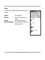
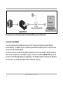
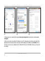
optris® PI NetBox ¯¯¯¯¯¯¯¯¯¯¯¯¯¯¯¯¯¯¯¯¯¯¯¯¯¯¯¯¯¯¯¯¯¯¯¯¯¯¯¯¯¯¯¯¯¯¯¯¯¯¯¯¯¯¯¯¯¯¯¯¯¯¯¯¯¯¯¯¯¯¯¯¯¯¯¯¯¯¯¯¯¯¯¯¯¯¯¯¯¯¯¯¯¯¯¯¯¯¯¯¯¯¯¯¯¯¯¯¯¯¯¯¯¯¯¯¯¯¯¯¯¯¯¯¯¯¯¯¯¯¯¯¯¯¯¯¯¯¯¯¯¯¯¯¯¯¯¯¯¯¯¯¯¯¯¯¯¯¯¯¯¯¯¯¯¯¯¯¯¯¯¯¯¯¯¯¯¯¯¯¯¯¯¯¯¯¯¯¯¯¯¯¯¯¯¯¯¯¯¯¯¯¯¯¯¯¯¯¯¯¯¯¯¯¯¯¯¯¯¯ Mini PC for optris PI series Operators manual Svensk generalagent och distributör: Sensotest AB - Girovägen 13 - 17562 Järfälla Tel: 08-564 733 80 - Fax: 08-564 733 89 - www.sensotest.se - [email protected] CE-Conformity The product complies with the following standards: EMC: Safety Regulations: EN 61326-1:2006 (Basic requirements) EN 61326-2-3:2006 EN 61010-1:2001 The product accomplishes the requirements of the EMC Directive 2004/108/EG and of the Low Voltage Directive 2006/95/EG. Optris GmbH Ferdinand-Buisson-Str. 14 D – 13127 Berlin GERMANY Tel.: +49-30-500 197-0 Fax: +49-30-500 197-10 E-mail: [email protected] Internet: www.optris.com Read the manual carefully before the initial start-up. The producer reserves the right to change the herein described specifications in case of technical advance of the product. References to other chapters are marked as [► ...]. Warranty Each single product passes through a quality process. Nevertheless, if failures occur please contact the customer service at once. The warranty period covers 24 months starting on the delivery date. After the warranty is expired the manufacturer guarantees additional 6 months warranty for all repaired or substituted product components. Warranty does not apply to damages, which result from misuse or neglect. The warranty also expires if you open the product. The manufacturer is not liable for consequential damage or in case of a non-intended use of the product. If a failure occurs during the warranty period the product will be replaced, calibrated or repaired without further charges. The freight costs will be paid by the sender. The manufacturer reserves the right to exchange components of the product instead of repairing it. If the failure results from misuse or neglect the user has to pay for the repair. In that case you may ask for a cost estimate beforehand. optris PI NetBox – E2013-04-D 1 Content Page Description Scope of Supply Maintenance Cautions Technical Data General Specifications Electrical Specifications Installation Controls and Connections Protective Housing Operation Operation Modes SD Card Status LEDs Switch Positions Remote Access to the NetBox Applications and Start Options Watchdog Autostart File transfer between NetBox and PC 2 3 3 4 4 5 5 5 6 7 8 10 10 10 11 12 13 16 20 21 22 Page Ethernet Direct Communication Ethernet Network Communication Stand-alone Operation System time Write protection filter System Recovery optris PI NetBox – E2013-04-D 23 30 34 36 37 39 Description The optris PI NetBox is a miniaturized PC which expands the optris PI series to a stand-alone solution or which works as a USB to Ethernet converter. This mode generates larger possible distances between process (IR camera) and process control (PC). The NetBox includes a Windows XP Professional operating system that allows the user to install additional software. The housing of the NetBox is made of anodized aluminum – the optional NetBox protection housing supports the usage in industrial environments (IP65/ NEMA-4 rating). Scope of Supply NetBox incl. micro SDHC card (8 GB) Power supply (100-240 VAC / 24 VDC) TVout adapter cable Ethernet cable, 1 m USB Recovery stick (2 GB) Rail mount adapter Operators manual optris PI NetBox – E2013-04-D 3 Maintenance The housing of the NetBox can be cleaned with a soft, humid tissue moistened with water or a water based cleaner. PLEASE NOTE: Never use cleaning compounds which contain solvents. Take care that no moisture infiltrates into the housing. Cautions Take care that no foreign substances penetrate into the venting slots of the NetBox. In case of problems or questions which may arise when you use the NetBox, please contact our service department. Please use only the threads in the housing or the supplied rail mount adapter for mechanical installation of the NetBox. Avoid mechanical violence – this may destroy the system (expiry of warranty). 4 optris PI NetBox – E2013-04-D Technical Data General Specifications Operating temperature Storage temperature Relative humidity Material (housing) Dimensions Weight 0...50 °C -20...75 °C 10...95 %, non condensing Anodized aluminum 113 mm x 57 mm x 48 mm (L x W x H) 315 g Vibration Shock Operating system IEC 68-2-6: 3G, 11 – 200 Hz, any axis IEC 68-2-27: 50G, 11 ms, any axis Windows XP Professional Electrical Specifications Power supply Power consumption Cooling 8...48 VDC or Power over Ethernet (PoE/ 1000BASE-T) 9,5 W (+ additional 2,5 W for IR camera) passive (active via integrated fans for ambient temperatures > 50 °C Board Processor Hard disc RAM Ports COM Express mini embedded board ® TM Intel Atom Z530/ 1,6 GHz 2 GB SSD 512 MB (DDR2, 533 MHz) 3x USB 2.0 1x Mini-USB 2.0 (slave mode) VGA/ TVout Ethernet (Gigabit Ethernet) microSDHC card (up to 32 GB) 6x Status LEDs (L1-L6) Extensions Additional functions optris PI NetBox – E2013-04-D 5 Installation The NetBox can be mounted easily on a DIN rail (TS35) according EN50022 using the supplied rail mount adapter. For this purpose please screw the 4 screws (M4) into the designated holes on the upper side of the NetBox housing. Now you can place the rail mount adapter on the housing and fix it with the 4 nuts. On the bottom side of the NetBox housing you will find 4 holes M2,5 which also can be used for mounting. Dimensions NetBox 6 optris PI NetBox – E2013-04-D Controls and Connections 1 2 3 4 5 6 7 8 Mounting holes for rail mount adapter USB 2.0 socket Ethernet socket Power supply socket Mode switch (S1/ S2) Mini USB socket (slave mode) Status-LEDs (L1-L6) microSDHC card slot 9 10 11 12 Cooling fans 2x USB 2.0 sockets VGA-/ TVout-connection Switch VGA/ TVout optris PI NetBox – E2013-04-D 7 Protective Housing IP65 Protective housing (Alu die-cast) [ACPINBPH] 8 optris PI NetBox – E2013-04-D Protective housing with power supply [ACPINBPHPS] IR camera inside CoolingJacket, connected to a NetBox via high temperature USB cable optris PI NetBox – E2013-04-D 9 Operation Operation Modes The NetBox can be used in three different operation modes: 1. Converter USB – Ethernet with direct connection to a PC (point-to-point connection) 2. Converter USB – Ethernet with connection of a PC via a network or via the internet 3. Stand-alone operation with an IR camera For powering the NetBox you either can use the supplied power adapter or a suitable industrial power supply with a voltage output between 8 VDC and 48 VDC [► Technical Data]. Alternatively the NetBox can also be powered via the Ethernet cable (PoE – Power over Ethernet). For this purpose a PoE injector is needed [part#: ACPIPOE]. SD Card The NetBox will be delivered with a 8 GB SDHC card which is already installed on the unit. If required you can exchange this card. The NetBox is supporting SD cards up to 32 GB capacity. To remove the card please take a ball pen or similar and push onto the card from outside carefully. Please take care when you insert a card that it is placed correctly into the according guide slot. 10 optris PI NetBox – E2013-04-D Status LEDs The NetBox is equipped with 6 status LEDs (L1-L6). optris PI NetBox – E2013-04-D 11 Switch Positions The mode switch is set default to S1. At position S2 the IR camera which is connected to the USB-A socket will be linked directly with the Mini-USB socket. With this you get a direct access to the IR camera from a PC which is connected to the Mini USB socket without changing cables on the NetBox. Mode switch (S1/ S2) Beside the VGA-socket you will find a switch for TVout. For the TVout mode please use the supplied TVout adapter cable. You can connect the cinch plug directly to a control monitor with CVBS (PAL) input (common name: Video In). Please connect at first the respective cable (VGA or TVout adapter cable) and then turn the switch in the appropriate position. 12 VGA/ TVout switch optris PI NetBox – E2013-04-D Remote Access to the NetBox For settings on the NetBox you can connect a keyboard and a mouse to the available USB sockets as well as a monitor to the VGA socket (or a TV monitor via the TVout adapter cable). ► Stand-alone Operation Another very simple way are remote control software, for example remote desktop (RDP) which is available on each Windows system or Ultra VNC which you will find on your software CD. After installation you can have access to the NetBox either from a PC directly connected over an Ethernet cable or from a PC which is 1) located anywhere and connected to the same network. Also remote connection via the internet is possible. To install Ultra VNC on your PC please start install.bat which is located on your PIConnect-CD in the folder \PI NetBox. After installation you will find the following short cuts on your desktop: Please use the short cut PI-NetBox UVNC for access to a NetBox which is directly connected to your PC over an Ethernet cable. After starting the UVNC viewer using this shortcut you should see immediately a window which shows the screen of the NetBox. Please use the short cut UltraVNC Viewer for access to a NetBox inside your network. After starting UVNC using this short cut you should see at first the following screen: 1) For remote access from outside to a NetBox connected to a company network please ask your system administrator for possibly necessary settings. optris PI NetBox – E2013-04-D 13 UltraVNC viewer setup 1) After input of the IP address of the NetBox, which in this case comes from a DHCP server, please press Connect. In the following screen you have to enter the password Remote and after this press Log On. Now you should see the screen of the NetBox. In chapter ► Ethernet Network Communication you will find an explanation how to figure out the IP address of the NetBox. With the UltraVNC Viewer it is possible to have simultaneous access to one NetBox from different PCs inside a network. 1) DHCP – Dynamic Host Configuration Protocol: allows the automatic integration of a computer into an existing network. 14 optris PI NetBox – E2013-04-D With NetBox Lister you can start a tool which will list all NetBoxes located in your network or directly connected to your PC. With this tool you can also do a time synchronization. You can scan either the whole network or a certain IP address range. The filter function allows a selective search for NetBoxes only. If you press one of the sync buttons you can synchronize all NetBoxes simultaneously or a previously selected one with the system time of your local PC (where NetBox Lister is running). The NetBox is factory default set to Central European Time (CET or CEST). Depending on the time zone setting of your local PC time differences after synchronizations are possible. In this case you have to change the time zone settings on the NetBox. ► System time The short cut NetBox Maintain is synchronizing the time automatically with a directly connected NetBox and is starting then automatically the UltraVNC viewer. optris PI NetBox – E2013-04-D 15 Applications and Start Options On the Desktop of the NetBox you will find the following short cuts: Application Start Config Application Start Manager starts the configuration dialog (Config Server) starts the program selected in the configuration dialog In the configuration dialog you can select programs which start automatically after booting the NetBox: No Imager Net Server PI Connect User defined 16 optris PI NetBox – E2013-04-D no automatic program start automatic start of the server application automatic start of the PI Connect user defined start of one of the both programs above The factory default setting of the NetBox starts the Imager Net Server application after booting the system. This program is needed for the operation modes: - Converter USB – Ethernet with direct connection to a PC (point-to-point connection) Converter USB – Ethernet with connection of a PC via a network or via the internet For the Stand-alone operation with an IR camera please start Application Start Config and then select PI Connect. In case you would like to start PI Connect or Imager Net Server with changed command line parameters [Args] please select User defined. Example The following configuration starts the PIConnect in the full screen mode: The start options selected in the configuration dialog are saved automatically in the NetBox and are available after a restart. optris PI NetBox – E2013-04-D 17 Screen of the NetBox – Imager Net Server Screen of the NetBox – PI Connect If an imager is connected to the NetBox you should see two active applications: Monitor Imager Net Server and Imager Net Server or PI Connect. 18 optris PI NetBox – E2013-04-D Appl. Watchdog Device Processing: Net connection Monitor Application Counter for the application monitoring function Device frequency Processing frequency Network frequency Display mode (VGA or TV-Out) monitored software application Information in the Monitor Imager Net Server – application window Menu File Devices Flag USB-Videogerät T (C, F, B) PIFin (A, D) HW Cnt. ADU (192, 144) Freq (D, P, N) Time Queue FOV, TR exit of the program shows the connected imager manual operation of the camera flag Serial number of the connected imager device Device temperatures (°C): C: FPA-Chip F: Flag temperature B: Housing temperature Status of the PIF input: A: Analog IN (AI) D: Digital IN (DI) Hardware-Counter (frame counter) ADU value of the center pixel (e.g. 192, 144 at PI4xx) Frequency (Hz): D: Device/ P: Processing/ N: Network Time per single frame Number of frames in network queue Field of view (horizontal) of the imager lens, Temperature range Information in the Imager Net Server – application window optris PI NetBox – E2013-04-D 19 Watchdog If, for any reason, the main software application (Imager Net Server or PIConnect) does not work properly (software hang-up or crash) or if the main application will be closed, the monitoring application (Monitor Imager Net Server) is restarting the program automatically. In addition also the Windows operating system is monitored permanently by a watchdog application – you see the symbol [WD] in the right part of the task bar: If the watchdog is recognizing a system error or problem it will restart the NetBox automatically. If you click with the right mouse button on this symbol you can open the watchdog window: Beside a status information and internal set parameters you can see the elapsed time since you started the NetBox and also the elapsed time of the operation period before the last restart. The number of restarts can be reset (right mouse button on WD symbol – Reset counter). Please note that all restarts (also not by the Watchdog initialized ones) will be counted here. 20 optris PI NetBox – E2013-04-D Autostart In the Windows Autostart folder of the NetBox the following shortcuts are set default: ewfMonitor MouseHider Watchdog Application Start Manager Write protection filter hides the mouse pointer after 10s of inactivity starts the Watchdog application starts the program which was selected in Application Start Config optris PI NetBox – E2013-04-D 21 File transfer between NetBox and PC To exchange files between the NetBox and a directly connected or in the network located PC please move the cursor to the title bar of the UltraVNC Viewer window and press the right mouse button. Start File Transfer. Alternatively you can also press the following button in the tool bar: In the following explorer window you see on the left side your local PC (LOCAL MACHINE) and on the right side the NetBox (REMOTE MACHINE). Now you can copy files between both computers via the network link by marking them and pressing Send or Receive. 22 optris PI NetBox – E2013-04-D Ethernet Direct Communication Please connect your imager with the supplied USB connection cable with the NetBox. Please connect your PC with an Ethernet cable with the NetBox. Now connect the power supply to the NetBox and to the mains. The NetBox will start to boot the system and should be ready to use after 2-3 minutes. You can check the status with the LEDs. At proper functioning now L1 and L5 should light up. Ethernet direct connection (point-to-point connection)/ NetBox powered via power supply If you use a PoE injector the power supply for the NetBox is not needed. In this case please connect the PoE injector as shown in the drawing below. At proper functioning now L1, L2 and L5 should light up. The used Ethernet cables should be at least category 5 cables (Cat-5 according ISO/IEC 11801). optris PI NetBox – E2013-04-D 23 Ethernet direct connection (point-to-point connection)/ NetBox powered via PoE injector Connection to the NetBox The communication with the NetBox is done via the TCP/ IP protocol (Transmission Control Protocol/ Internet Protocol). The NetBox can get its IP address (Internet Protocol address) either from a DHCP server or it can work with a fixed IP address. On a direct connection to a PC both, the NetBox as well as the PC must use a fixed IP address because no DHCP server is available here. The NetBox is using in this case the IP address 192.168.0.100. On your PC you have to do the following settings once (depending on the operating system the procedure can differ from the here shown – the following description refers to a Windows 7 system). 24 optris PI NetBox – E2013-04-D 1. Go to System controls; open Network and Sharing Center. 2. If you have an existing connection to a network (company network e.g.) you should see the following information: If your PC is not connected to any network, please go to Change adapter settings after you opened the Network and Sharing Center. Now go to Local Area Connection, right mouse button: Properties. [continue at item 4] 3. Go to Local Area Connection – a status screen according [1] will be shown. Then go to Properties. 4. In the following window [2] mark Internet protocol Version 4 (TCP/IPv4) and go again to Properties. optris PI NetBox – E2013-04-D 25 [1] [2] [3] 5. Please open now in window [3] the register Alternate Configuration and activate the checkbox User configured. 6. Now you can enter a user defined IP address for your PC. Please take care that the network part of the address has to be identical with the network part of the IP address of the NetBox, thus 192.168.0. For the host part you have to use an address which is different from the one of the NetBox (100), so you may use 1 for example. 26 optris PI NetBox – E2013-04-D After you have made these settings and connected your PC with the NetBox using an Ethernet cable your PC will establish a point-to-point connection. This procedure can take several minutes. In the Network and Sharing Center your network will now be shown up as a non-identified network. Please start now the PIConnect on your PC and open the menu item Tools/ Extended/ Remote devices.... In the window which is appearing you should set a hook on Enable and enter the IP address of the NetBox (192.168.0.100). Press OK. The software will establish a connection to the remote device (imager) automatically. optris PI NetBox – E2013-04-D 27 Search for network devices in PIConnect Device selection in PIConnect Under Remote framerate you can enter the desired frame rate which should be transmitted via the network. Under the menu item Devices the imager which is connected to the NetBox shows up now. The following functions can be selected here: Connect Restart Reboot Remove 28 manual connection with the remote device restart of the Imager Net Server application on the NetBox reboot of the NetBox remove of the device entry in this menu optris PI NetBox – E2013-04-D If the used imager is connected for the first time to the NetBox the following message appears: Please confirm with Yes. The calibration files will be transferred automatically from your PC to the NetBox and stored there. Now you should see the live picture from the imager on your PC. Alternatively you can copy the calibration data also manually via an USB stick into the NetBox folder D:\Imager\Cali. optris PI NetBox – E2013-04-D 29 Ethernet Network Communication Please connect your imager with the supplied USB connection cable with the NetBox. Please connect the Ethernet connection of the NetBox with a network or internet (via a router e.g.). Now connect the power supply to the NetBox and to the mains. The NetBox will start to boot the system and should be ready to use after 2-3 minutes. You can check the status with the LEDs. At proper functioning now L1 and L5 should light up. Ethernet network connection/ NetBox powered via power supply If you use a PoE injector the power supply for the NetBox is not needed. In this case please connect the PoE injector as shown in the drawing below. At proper functioning now L1, L2 and L5 should light up. 30 optris PI NetBox – E2013-04-D Ethernet network connection/ NetBox powered via PoE injector If the NetBox is used in a network it gets its IP address from a DHCP server. In order to find the NetBox in the PIConnect of your local PC the address range of the local network must be known. For this purpose please start the program NetBox Lister. ► Remote Access to the NetBox Please start now the PIConnect on your local PC and open the menu Tools/ Extended/ Remote devices.... In the window which opens set a hook on Enable and enter the address range of your local network under Detect devices. The fourth block should have the range 0 to 255. If you now press Ping all computers inside the selected address range will be shown. Under Remote framerate you can enter the desired frame rate which should be transmitted via the network. optris PI NetBox – E2013-04-D 31 For a faster search you should activate the filter and enter NetBox. Now only computers with NetBox in their name will be shown. Under Hosts you should see now your NetBox. Please mark this and press OK. Under the menu item Devices the imager which is connected to the NetBox shows up now. The following functions can be selected here: Connect Restart Reboot Remove 32 manual connection with the remote device restart of the Imager Net Server application on the NetBox reboot of the NetBox remove of the device entry in this menu optris PI NetBox – E2013-04-D If the used imager is connected for the first time to the NetBox the following message appears: Please confirm with Yes. The calibration files will be transferred automatically from your PC to the NetBox and stored there. Now you should see the live picture from the imager on your PC. Alternatively you can copy the calibration data also manually via an USB stick into the NetBox folder D:\Imager\Cali. optris PI NetBox – E2013-04-D 33 Stand-alone Operation As a stand-alone PC the NetBox can expand a IR camera to a separate system. For this operation mode you should connect a VGA or TV monitor and a USB keyboard to the NetBox. In addition the system can also be controlled via a remote access over an Ethernet connection. [► Remote Access to the NetBox] Stand-alone operation/ NetBox powered via power supply After booting the NetBox the first time you will see the Imager Net Server application. Please close the monitor program and change it to PI Connect in the configuration dialog (Application Start Config). ► Operation/ Applications and Start Options 34 optris PI NetBox – E2013-04-D USB Driver The USB-IR-camera as well as USB sticks, USB keyboards or USB mouses don’t need a special device driver. System messages to new installed USB hardware devices are therefore suppressed to ensure a most comfortable use of the NetBox with the recommended standard components. If you connect other USB devices which need a specific driver installation it might be necessary to start the installation process manually in the device manager. optris PI NetBox – E2013-04-D 35 System time The NetBox does not contain a CMOS battery which is normally used for keeping the system time if the computer is switched off. On the NetBox therefore the current time will be saved regularly during operation. On a restart of the NetBox the system time is proceeding automatically starting at the last saved time. With this you have a chronology of imager recordings which use an automatic file name generation. If the NetBox has a connection to the internet, the current time will be synchronized automatically via an internet time server after a certain period. A manual time synchronization can be done with the tools NetBox Maintain und NetBox Lister from a PC which is directly or via network connected. ► Remote Access to the NetBox You can change the set time zone in the tab Time Zone. To save the new setting permanently you have to deactivate the ► Write Protection Filter temporarily. 36 optris PI NetBox – E2013-04-D Write Protection Filter The NetBox has a factory pre-installed write protection filter. This filter is protecting reliably the operating system and the complete drive C and allows a switch-off of the device without a shut down of the operating system. The write protection filter (ewfMonitor) can be seen as shortcut in the start menu and as symbol in the task bar. The colors have the following meaning: red dot: safe mode green dot: write mode The NetBox should be used only with an activated write protection filter [red dot]. Write protection filter as short cut in folder Autostart optris PI NetBox – E2013-04-D 37 To save changed settings or if you want to install additional software the write protection has to be deactivated temporarily. To do this please move the cursor to the red dot in the task bar and push the right mouse button: You can select between four different actions: Save and reboot Save and shutdown Standard write mode Reboot Changes will be saved + Restart Changes will be saved + shut down Switch into the write mode (green dot) Restart without saving of changes The SSD drive of the NetBox has by factory default two partitions. The write protection refers to partition C only. On the partition D you can save application data. On drive D also the calibration data of the infrared imager are stored. 38 optris PI NetBox – E2013-04-D System Recovery In case a recovery of the Windows operating system of the NetBox is necessary you should use the supplied USB recovery stick. Follow the steps described hereafter. Do not disconnect power from the NetBox during the recovery procedure. After the system recovery the NetBox has the factory default settings. All data which was stored before on the SSD will get lost. Step 1: Please connect a VGA monitor and a USB keyboard with the NetBox. Connect the USB recovery stick to a free USB port and switch on the NetBox. If you see the following start screen please press the ESC button for at least 2 seconds (keep pressed). Start screen of the NetBox optris PI NetBox – E2013-04-D 39 Step 2: Now you should see the following screen – select USB device and then press Enter. The next screen shows the available USB stick. Please confirm with Enter. Confirm with Enter 40 Screens during system recovery optris PI NetBox – E2013-04-D Step 3: After the complete system recovery the NetBox will be automatically shut down and switched off (all LEDs are off). Now you should disconnect for a short time the power (disconnect the power supply). After reconnecting power and booting of the system you should see the following message: Please press Next Select Random SID and then Next Step 4: In the next window you can rename the NetBox (optional). Please note that the new name should have at maximum 15 characters. Press two times Next. Now the system will be shut down again. Your NetBox is now ready for use again. optris PI NetBox – E2013-04-D 41 Rename the NetBox (optional) 42 optris PI NetBox – E2013-04-D