1
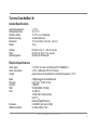
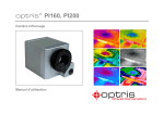
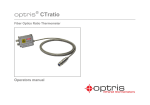
optris® PI LightWeight Kit ¯¯¯¯¯¯¯¯¯¯¯¯¯¯¯¯¯¯¯¯¯¯¯¯¯¯¯¯¯¯¯¯¯¯¯¯¯¯¯¯¯¯¯¯¯¯¯¯¯¯¯¯¯¯¯¯¯¯¯¯¯¯¯¯¯¯¯¯¯¯¯¯¯¯¯¯¯¯¯¯¯¯¯¯¯¯¯¯¯¯¯¯¯¯¯¯¯¯¯¯¯¯¯¯¯¯¯¯¯¯¯¯¯¯¯¯¯¯¯¯¯¯¯¯¯¯¯¯¯¯¯¯¯¯¯¯¯¯¯¯¯¯¯¯¯¯¯¯¯¯¯¯¯¯¯¯¯¯¯¯¯¯¯¯¯¯¯¯¯¯¯¯¯¯¯¯¯¯¯¯¯¯¯¯¯¯¯¯¯¯¯¯¯¯¯¯¯¯¯¯¯¯¯¯¯¯¯¯¯¯¯¯¯¯¯¯¯¯¯¯ Miniature lightweight PC with IR camera for flight applications Operators manual Svensk generalagent och distributör: Sensotest AB - Girovägen 13 - 17562 Järfälla Tel: 08-564 733 80 - Fax: 08-564 733 89 - www.sensotest.se - [email protected] CE-Conformity The product complies with the following standards: EMC: Safety Regulations: EN 61326-1:2006 (Basic requirements) EN 61326-2-3:2006 EN 61010-1:2001 The product accomplishes the requirements of the EMC Directive 2004/108/EG and of the Low Voltage Directive 2006/95/EG. Optris GmbH Ferdinand-Buisson-Str. 14 D – 13127 Berlin GERMANY Tel.: +49-30-500 197-0 Fax: +49-30-500 197-10 E-mail: [email protected] Internet: www.optris.com Read the manual carefully before the initial start-up. The producer reserves the right to change the herein described specifications in case of technical advance of the product. References to other chapters are marked as [► ...]. Warranty Each single product passes through a quality process. Nevertheless, if failures occur please contact the customer service at once. The warranty period covers 24 months starting on the delivery date. After the warranty is expired the manufacturer guarantees additional 6 months warranty for all repaired or substituted product components. Warranty does not apply to damages, which result from misuse or neglect. The warranty also expires if you open the product. The manufacturer is not liable for consequential damage or in case of a non-intended use of the product. If a failure occurs during the warranty period the product will be replaced, calibrated or repaired without further charges. The freight costs will be paid by the sender. The manufacturer reserves the right to exchange components of the product instead of repairing it. If the failure results from misuse or neglect the user has to pay for the repair. In that case you may ask for a cost estimate beforehand. optris PI LightWeight Kit – E2013-04-B 1 Content Page Description Scope of Supply Important Notes Technical Data NetBox LW General Specifications Electrical Specifications Technical Data PI 400 LW/ PI 450 LW General Specifications Electrical Specifications Measurement Specifications Optical Specifications Installation Dimensions PI 400 LW/ PI 450 LW Dimensions PI NetBox LW Controls and Connections Operation Stand-alone Operation Start a Recording SD Card Status LEDs Switch Positions Operation Modes of the NetBox LW 2 3 3 4 5 5 5 6 6 6 6 7 8 11 12 13 14 14 15 16 16 17 17 Page Remote Access to the NetBox LW Applications and Start Options Watchdog Autostart File transfer between NetBox LW and PC Ethernet Direct Communication Ethernet Network Communication System time Write Protection Filter System Recovery Basics of Infrared Thermometry Emissivity optris PI LightWeight Kit – E2013-04-B 18 21 25 26 27 28 35 40 41 43 47 50 Description Thank you for choosing the optris PI LightWeight Kit! The optris PI LightWeight Kit consists of a miniaturized lightweight PC (PI NetBox LW) and a weightoptimized optris PI400 LW or PI450 LW infrared camera. With 380 g the system is ideally suited for radiometric infrared recordings from the air like for maintenance work and quality inspections of solar and wind power systems and for building thermography. The PI NetBox LW (Miniature-PC) includes a Windows XP Professional operating system that allows onflight recording of infrared videos with up to 35 Hz. The optris PI400 LW or 450 LW calculates the surface temperature based on the emitted infrared energy of objects [► Basics of Infrared Thermometry]. The two-dimensional detector (FPA - focal plane array) with 382 x 288 pixels allows a measurement of an area which will be shown as thermal image using standardized color palettes. The radiometric processing of the picture data enables the user to do a comfortable detailed analysis with the software PI Connect after flight. Scope of Supply PI NetBox LW (LightWeight) incl. micro SDHC card (8 GB) Power supply (100-240 VAC / 24 VDC) Power cable (with open ends for direct connection to a Lithium battery) Video adapter cable Ethernet cable, 1 m USB Recovery stick (2 GB) optris PI400 LW or PI450 LW (LightWeight) with one lens and fixed mounted USB cable (30 cm) Software PIConnect Operators manual optris PI LightWeight Kit – E2013-04-B 3 Important Notes The optris PI is a precise instrument and contains a sensitive infrared detector and a highquality lens. The alignment of the camera to intensive energy sources (high power laser or reflections of such equipment, e.g.) can have effect on the accuracy of the measurement or can cause an irreparable defect of the infrared detector. Avoid static electricity, arc welders, and induction heaters. Keep away from very strong EMF (electromagnetic fields). Avoid abrupt changes of the ambient temperature. In case of problems or questions which may arise when you use the infrared camera, please contact our service department. Cleaning The housing of the NetBox LW can be cleaned with a soft, humid tissue moistened with water or a water based cleaner. PLEASE NOTE: Never use cleaning compounds which contain solvents. Take care that no moisture infiltrates into the housing. Lens cleaning Blow off loose particles using clean compressed air. The lens surface can be cleaned with a soft, humid tissue moistened with water or a water based glass cleaner. Take care that no foreign substances penetrate into the venting slots of the NetBox LW. 4 optris PI LightWeight Kit – E2013-04-B Technical Data NetBox LW General Specifications Operating temperature Storage temperature Relative humidity Material (housing) Dimensions Weight 0...50 °C -20...75 °C 10...95 %, non condensing Anodized aluminum 112 mm x 58 mm x 54 mm (L x W x H) 160 g Vibration Shock Operating system IEC 68-2-6: 3G, 11 – 200 Hz, any axis IEC 68-2-27: 50G, 11 ms, any axis Windows XP Professional Electrical Specifications Power supply Power consumption Cooling 8...48 VDC or Power over Ethernet (PoE/ 1000BASE-T) 9,5 W (+ additional 2,5 W for PI camera) passive (active via integrated fan for ambient temperatures > 50 °C Board Processor Hard disc RAM Ports COM Express mini embedded board ® TM Intel Atom Z530/ 1,6 GHz 2 GB SSD 512 MB (DDR2, 533 MHz) 3x USB 2.0 1x Mini-USB 2.0 (slave mode) VGA/ TVout Ethernet (Gigabit Ethernet) microSDHC card (up to 32 GB) 6x Status LEDs (L1-L6) Extensions Additional functions optris PI LightWeight Kit – E2013-04-B 5 Technical Data PI 400 LW / PI 450 LW General Specifications Environmental rating Ambient temperature Storage temperature Relative humidity Material (housing) Dimensions Weight (incl. lens) Cable length (USB 2.0) Vibration Shock IP67 (NEMA-4) 0...50 °C [PI 400 LW] / 0...70 °C [PI 450 LW] -40...70 °C [PI 400 LW] / -40...85 °C [PI 450 LW] 10...95 %, non condensing aluminum, anodized/ plastic 46 x 56 x 84 - 88 mm (depending on lens) 220 g 30 cm IEC 68-2-6: 3G, 11 – 200Hz, any axis IEC 68-2-27: 50G, 11ms, any axis Electrical Specifications Power Supply Current draw Digital interface 5 VDC (powered via USB 2.0 interface) max. 500 mA USB 2.0 Measurement Specifications Temperature ranges Detector Spectral range Lenses (FOV) 1) System accuracy 1) 6 -20...100 °C; 0...250 °C; 120...900 °C UFPA, 382 x 288 pixels 7.5...13 µm 38° x 29°; 62° x 49° ±2 °C or ±2 % At ambient temperature 235 °C; whichever is greater optris PI LightWeight Kit – E2013-04-B Temperature resolution (NETD) Frame rate Emissivity Software 1) PI 400 LW : 0,08 K with 38° and 62°; 0,1 K with 13° 1) PI 450 LW : 0,04 K with 38° and 62°; 0,06 K with 13° 80 Hz 0,100...1,000 (adjustable via software) PI Connect Optical Specifications For the PI 400 LW and PI 450 LW two different lenses are available: 38° x 29° and 62° x 49° FOV. Different parameters are important if using infrared cameras. They display the connection between the distance of the measured object and the size of the pixel (please see table at the end of this section). Note Please make sure that the focus of the infrared camera is adjusted correctly. For focusing please turn the lens. 1) Value is valid at 40 Hz and 25°C room temperature optris PI LightWeight Kit – E2013-04-B 7 8 optris PI LightWeight Kit – E2013-04-B Installation The PI 400 LW/ 450 LW are equipped with two metric M4 thread holes on the bottom side (6 mm depth) and can be installed either directly via these threads or with help of the tripod mount (also on bottom side). The separate PI camera sensing head can be mounted on the stabilization platform of a drone together with a visual camera (in the picture: GoPro camera). The NetBox PC can be mounted separate. Installation PI LightWeight on a drone together with GoPro HD camera optris PI LightWeight Kit – E2013-04-B 9 The IR camera PI4xx LW will be delivered in an alu case; the NetBox LW incl. accessories will be delivered in a slider carton box. ► Scope of Supply For a mobile use you can arrange all components of the system also inside the camera case as shown in the below picture. Single foam parts of the case can be easily removed for that purpose. Arrangement of the PI LightWeight kit inside the camera case 10 optris PI LightWeight Kit – E2013-04-B Dimensions PI 400 LW/ PI 450 LW optris PI LightWeight Kit – E2013-04-B 11 Dimensions PI NetBox LW 12 optris PI LightWeight Kit – E2013-04-B Controls and Connections 1 2 3 4 5 Cooling fan Videoout socket USB 2.0 socket Power supply socket Status-LEDs (L1-L6) 6 7 8 9 10 USB 2.0 socket Ethernet socket Mode switch (S1/ S2) Mini USB socket (slave mode) microSDHC card slot optris PI LightWeight Kit – E2013-04-B 13 Operation Stand-alone Operation As a stand-alone PC the NetBox LW expands the IR cameras PI400 LW and PI450 LW to a system for radiometric infrared video recording. For a self-contained power supply we recommend a lithium-polymer battery with a voltage between 8 and 14 VDC. Recommended video system integration of the PI LightWeight 14 optris PI LightWeight Kit – E2013-04-B After powering the NetBox LW the system will boot and is ready after 2-3 minutes. A video monitor which is connected to the system will show then the IR live picture of the camera in full screen mode. Start a Recording At the backside of the IR camera you will find a red sliding switch. To start a recording please move the switch into the right position. If you move the switch back into the left position the recording will be stopped. optris PI LightWeight Kit – E2013-04-B 15 SD Card The NetBox LW will be delivered with a 8 GB SDHC card which is already installed on the unit. If required you can exchange this card. The NetBox is supporting SD cards up to 32 GB capacity. To remove the card please take a ball pen or similar and push onto the card from outside carefully. Please take care when you insert a card that it is placed correctly into the according guide slot. Status LEDs The NetBox LW is equipped with 6 status LEDs (L1-L6). 16 optris PI LightWeight Kit – E2013-04-B Switch Positions The mode switch is set default to S1. At position S2 the IR camera which is connected to the USB-A socket will be linked directly with the Mini-USB socket. With this you get a direct access to the IR camera from a PC which is connected to the Mini USB socket without changing cables on the NetBox LW. Mode switch (S1/ S2) Operation Modes of the NetBox LW The NetBox LW can be used in three different operation modes: 1. Stand-alone operation with an IR camera (Standard mode) 2. Ethernet direct connection to a PC (point-to-point connection) 3. Ethernet communication via a network or via the internet For powering the NetBox you can use instead of a lithium-polymer battery also the supplied power adapter. Alternatively the NetBox can also be powered via the Ethernet cable (PoE – Power over Ethernet). For this purpose a PoE injector is needed [part#: ACPIPOE]. optris PI LightWeight Kit – E2013-04-B 17 Remote Access to the NetBox LW For settings on the NetBox LW you can connect a keyboard and a mouse to the available USB sockets as well as a monitor to the VGA socket (or a TV monitor via the TVout adapter cable). ► Stand-alone Operation Another very simple way are remote control software, for example remote desktop (RDP) which is available on each Windows system or Ultra VNC which you will find on your software CD. After installation you can have access to the NetBox either from a PC directly connected over an Ethernet cable or from a PC which is 1) located anywhere and connected to the same network. Also remote connection via the internet is possible. To install Ultra VNC on your PC please start install.bat which is located on your PIConnect-CD in the folder \PI NetBox. After installation you will find the following short cuts on your desktop: Please use the short cut PI-NetBox UVNC for access to a NetBox which is directly connected to your PC over an Ethernet cable. After starting the UVNC viewer using this shortcut you should see immediately a window which shows the screen of the NetBox. Please use the short cut UltraVNC Viewer for access to a NetBox inside your network. After starting UVNC using this short cut you should see at first the following screen: 1) For remote access from outside to a NetBox LW connected to a company network please ask your system administrator for possibly necessary settings. 18 optris PI LightWeight Kit – E2013-04-B UltraVNC viewer setup 1) After input of the IP address of the NetBox, which in this case comes from a DHCP server, please press Connect. In the following screen you have to enter the password Remote and after this press Log On. Now you should see the screen of the NetBox. In chapter ► Ethernet Network Communication you will find an explanation how to figure out the IP address of the NetBox. With the UltraVNC Viewer it is possible to have simultaneous access to one NetBox from different PCs inside a network. 1) DHCP – Dynamic Host Configuration Protocol: allows the automatic integration of a computer into an existing network. optris PI LightWeight Kit – E2013-04-B 19 With NetBox Lister you can start a tool which will list all NetBoxes located in your network or directly connected to your PC. With this tool you can also do a time synchronization. You can scan either the whole network or a certain IP address range. The filter function allows a selective search for NetBoxes only. If you press one of the sync buttons you can synchronize all NetBoxes simultaneously or a previously selected one with the system time of your local PC (where NetBox Lister is running). The NetBox is factory default set to Central European Time (CET or CEST). Depending on the time zone setting of your local PC time differences after synchronizations are possible. In this case you have to change the time zone settings on the NetBox. ► System time The short cut NetBox Maintain is synchronizing the time automatically with a directly connected NetBox and is starting then automatically the UltraVNC viewer. 20 optris PI LightWeight Kit – E2013-04-B Applications and Start Options On the Desktop of the NetBox LW you will find the following short cuts: Application Start Config Application Start Manager starts the configuration dialog (Config Server) starts the program selected in the configuration dialog In the configuration dialog you can select programs which start automatically after booting the NetBox: No Imager Net Server PI Connect User defined optris PI LightWeight Kit – E2013-04-B no automatic program start automatic start of the server application automatic start of the PI Connect user defined start of one of the both programs above 21 After booting the system the factory default setting of the NetBox LW starts the PI Connect in full screen mode with a special flight layout (Selection: User defined in Application Start Config). The Imager Net Server application is needed for the operation modes: - Ethernet direct connection to a PC (point-to-point connection) Ethernet communication via a network or via the internet In case you would like to start PI Connect or Imager Net Server with changed command line parameters [Args] please select User defined. Example The following configuration starts the PIConnect in the full screen mode: The start options selected in the configuration dialog are saved automatically in the NetBox and are available after a restart. 22 optris PI LightWeight Kit – E2013-04-B Screen of the NetBox LW – Imager Net Server Screen of the NetBox LW – PI Connect If an imager is connected to the NetBox you should see two active applications: Monitor Imager Net Server and Imager Net Server or PI Connect. optris PI LightWeight Kit – E2013-04-B 23 Appl. Watchdog Device Processing: Net connection Monitor Application Counter for the application monitoring function Device frequency Processing frequency Network frequency Display mode (VGA or TV-Out) monitored software application Information in the Monitor Imager Net Server – application window Menu File Devices Flag USB-Videogerät T (C, F, B) PIFin (A, D) HW Cnt. ADU (192, 144) Freq (D, P, N) Time Queue FOV, TR exit of the program shows the connected imager manual operation of the camera flag Serial number of the connected imager device Device temperatures (°C): C: FPA-Chip F: Flag temperature B: Housing temperature Status of the PIF input: A: Analog IN (AI) D: Digital IN (DI) Hardware-Counter (frame counter) ADU value of the center pixel (e.g. 192, 144 at PI4xx) Frequency (Hz): D: Device/ P: Processing/ N: Network Time per single frame Number of frames in network queue Field of view (horizontal) of the imager lens, Temperature range Information in the Imager Net Server – application window 24 optris PI LightWeight Kit – E2013-04-B Watchdog If, for any reason, the main software application (Imager Net Server or PIConnect) does not work properly (software hang-up or crash) or if the main application will be closed, the monitoring application (Monitor Imager Net Server) is restarting the program automatically. In addition also the Windows operating system is monitored permanently by a watchdog application – you see the symbol [WD] in the right part of the task bar: If the watchdog is recognizing a system error or problem it will restart the NetBox automatically. If you click with the right mouse button on this symbol you can open the watchdog window: Beside a status information and internal set parameters you can see the elapsed time since you started the NetBox and also the elapsed time of the operation period before the last restart. The number of restarts can be reset (right mouse button on WD symbol – Reset counter). Please note that all restarts (also not by the Watchdog initialized ones) will be counted here. optris PI LightWeight Kit – E2013-04-B 25 Autostart In the Windows Autostart folder of the NetBox LW the following shortcuts are set default: ewfMonitor MouseHider Watchdog Application Start Manager 26 Write protection filter hides the mouse pointer after 10s of inactivity starts the Watchdog application starts the program which was selected in Application Start Config optris PI LightWeight Kit – E2013-04-B File transfer between NetBox LW and PC To exchange files between the NetBox and a directly connected or in the network located PC please move the cursor to the title bar of the UltraVNC Viewer window and press the right mouse button. Start File Transfer. Alternatively you can also press the following button in the tool bar: In the following explorer window you see on the left side your local PC (LOCAL MACHINE) and on the right side the NetBox (REMOTE MACHINE). Now you can copy files between both computers via the network link by marking them and pressing Send or Receive. optris PI LightWeight Kit – E2013-04-B 27 Ethernet Direct Communication Please connect your imager with the supplied USB connection cable with the NetBox. Please connect your PC with an Ethernet cable with the NetBox. Now connect the power supply to the NetBox and to the mains. The NetBox will start to boot the system and should be ready to use after 2-3 minutes. You can check the status with the LEDs. At proper functioning now L1 and L5 should light up. Ethernet direct connection (point-to-point connection)/ NetBox LW powered via power supply If you use a PoE injector the power supply for the NetBox is not needed. In this case please connect the PoE injector as shown in the drawing below. At proper functioning now L1, L2 and L5 should light up. The used Ethernet cables should be at least category 5 cables (Cat-5 according ISO/IEC 11801). 28 optris PI LightWeight Kit – E2013-04-B Ethernet direct connection (point-to-point connection)/ NetBox LW powered via PoE injector Connection to the NetBox LW The communication with the NetBox is done via the TCP/ IP protocol (Transmission Control Protocol/ Internet Protocol). The NetBox can get its IP address (Internet Protocol address) either from a DHCP server or it can work with a fixed IP address. On a direct connection to a PC both, the NetBox as well as the PC must use a fixed IP address because no DHCP server is available here. The NetBox is using in this case the IP address 192.168.0.100. On your PC you have to do the following settings once (depending on the operating system the procedure can differ from the here shown – the following description refers to a Windows 7 system). optris PI LightWeight Kit – E2013-04-B 29 1. Go to System controls; open Network and Sharing Center. 2. If you have an existing connection to a network (company network e.g.) you should see the following information: If your PC is not connected to any network, please go to Change adapter settings after you opened the Network and Sharing Center. Now go to Local Area Connection, right mouse button: Properties. [continue at item 4] 3. Go to Local Area Connection – a status screen according [1] will be shown. Then go to Properties. 4. In the following window [2] mark Internet protocol Version 4 (TCP/IPv4) and go again to Properties. 30 optris PI LightWeight Kit – E2013-04-B [1] [2] [3] 5. Please open now in window [3] the register Alternate Configuration and activate the checkbox User configured. 6. Now you can enter a user defined IP address for your PC. Please take care that the network part of the address has to be identical with the network part of the IP address of the NetBox, thus 192.168.0. For the host part you have to use an address which is different from the one of the NetBox (100), so you may use 1 for example. optris PI LightWeight Kit – E2013-04-B 31 After you have made these settings and connected your PC with the NetBox using an Ethernet cable your PC will establish a point-to-point connection. This procedure can take several minutes. In the Network and Sharing Center your network will now be shown up as a non-identified network. Please start now the PIConnect on your PC and open the menu item Tools/ Extended/ Remote devices.... In the window which is appearing you should set a hook on Enable and enter the IP address of the NetBox (192.168.0.100). Press OK. The software will establish a connection to the remote device (imager) automatically. 32 optris PI LightWeight Kit – E2013-04-B Search for network devices in PIConnect Device selection in PIConnect Under Remote framerate you can enter the desired frame rate which should be transmitted via the network. Under the menu item Devices the imager which is connected to the NetBox shows up now. The following functions can be selected here: Connect Restart Reboot Remove manual connection with the remote device restart of the Imager Net Server application on the NetBox reboot of the NetBox remove of the device entry in this menu optris PI LightWeight Kit – E2013-04-B 33 If the used imager is connected for the first time to the NetBox the following message appears: Please confirm with Yes. The calibration files will be transferred automatically from your PC to the NetBox and stored there. Now you should see the live picture from the imager on your PC. Alternatively you can copy the calibration data also manually via an USB stick into the NetBox folder D:\Imager\Cali. 34 optris PI LightWeight Kit – E2013-04-B Ethernet Network Communication Please connect your imager with the supplied USB connection cable with the NetBox. Please connect the Ethernet connection of the NetBox with a network or internet (via a router e.g.). Now connect the power supply to the NetBox and to the mains. The NetBox will start to boot the system and should be ready to use after 2-3 minutes. You can check the status with the LEDs. At proper functioning now L1 and L5 should light up. Ethernet network connection/ NetBox LW powered via power supply If you use a PoE injector the power supply for the NetBox is not needed. In this case please connect the PoE injector as shown in the drawing below. At proper functioning now L1, L2 and L5 should light up. optris PI LightWeight Kit – E2013-04-B 35 Ethernet network connection/ NetBox LW powered via PoE injector If the NetBox is used in a network it gets its IP address from a DHCP server. In order to find the NetBox in the PIConnect of your local PC the address range of the local network must be known. For this purpose please start the program NetBox Lister. ► Remote Access to the NetBox Please start now the PIConnect on your local PC and open the menu Tools/ Extended/ Remote devices.... In the window which opens set a hook on Enable and enter the address range of your local network under Detect devices. The fourth block should have the range 0 to 255. If you now press Ping all computers inside the selected address range will be shown. Under Remote framerate you can enter the desired frame rate which should be transmitted via the network. 36 optris PI LightWeight Kit – E2013-04-B For a faster search you should activate the filter and enter NetBox. Now only computers with NetBox in their name will be shown. Under Hosts you should see now your NetBox. Please mark this and press OK. Under the menu item Devices the imager which is connected to the NetBox shows up now. The following functions can be selected here: Connect Restart Reboot Remove manual connection with the remote device restart of the Imager Net Server application on the NetBox reboot of the NetBox remove of the device entry in this menu optris PI LightWeight Kit – E2013-04-B 37 If the used imager is connected for the first time to the NetBox the following message appears: Please confirm with Yes. The calibration files will be transferred automatically from your PC to the NetBox and stored there. Now you should see the live picture from the imager on your PC. Alternatively you can copy the calibration data also manually via an USB stick into the NetBox folder D:\Imager\Cali. 38 optris PI LightWeight Kit – E2013-04-B USB Driver The USB-IR-camera as well as USB sticks, USB keyboards or USB mouses don’t need a special device driver. System messages to new installed USB hardware devices are therefore suppressed to ensure a most comfortable use of the NetBox with the recommended standard components. If you connect other USB devices which need a specific driver installation it might be necessary to start the installation process manually in the device manager. optris PI LightWeight Kit – E2013-04-B 39 System time The NetBox LW does not contain a CMOS battery which is normally used for keeping the system time if the computer is switched off. On the NetBox therefore the current time will be saved regularly during operation. On a restart of the NetBox the system time is proceeding automatically starting at the last saved time. With this you have a chronology of imager recordings which use an automatic file name generation. If the NetBox has a connection to the internet, the current time will be synchronized automatically via an internet time server after a certain period. A manual time synchronization can be done with the tools NetBox Maintain und NetBox Lister from a PC which is directly or via network connected. ► Remote Access to the NetBox You can change the set time zone in the tab Time Zone. To save the new setting permanently you have to deactivate the ► Write Protection Filter temporarily. 40 optris PI LightWeight Kit – E2013-04-B Write Protection Filter The NetBox LW has a factory pre-installed write protection filter. This filter is protecting reliably the operating system and the complete drive C and allows a switch-off of the device without a shut down of the operating system. The write protection filter (ewfMonitor) can be seen as shortcut in the start menu and as symbol in the task bar. The colors have the following meaning: red dot: safe mode green dot: write mode The NetBox should be used only with an activated write protection filter [red dot]. Write protection filter as short cut in folder Autostart optris PI LightWeight Kit – E2013-04-B 41 To save changed settings or if you want to install additional software the write protection has to be deactivated temporarily. To do this please move the cursor to the red dot in the task bar and push the right mouse button: You can select between four different actions: Save and reboot Save and shutdown Standard write mode Reboot Changes will be saved + Restart Changes will be saved + shut down Switch into the write mode (green dot) Restart without saving of changes The SSD drive of the NetBox has by factory default two partitions. The write protection refers to partition C only. On the partition D you can save application data. On drive D also the calibration data of the infrared imager are stored. 42 optris PI LightWeight Kit – E2013-04-B System Recovery In case a recovery of the Windows operating system of the NetBox LW is necessary you should use the supplied USB recovery stick. Follow the steps described hereafter. Do not disconnect power from the NetBox during the recovery procedure. After the system recovery the NetBox has the factory default settings. All data which was stored before on the SSD will get lost. Step 1: Please connect a VGA monitor and a USB keyboard with the NetBox. Connect the USB recovery stick to a free USB port and switch on the NetBox. If you see the following start screen please press the ESC button for at least 2 seconds (keep pressed). Start screen of the NetBox LW optris PI LightWeight Kit – E2013-04-B 43 Step 2: Now you should see the following screen – select USB device and then press Enter. The next screen shows the available USB stick. Please confirm with Enter. Confirm with Enter 44 Screens during system recovery optris PI LightWeight Kit – E2013-04-B Step 3: After the complete system recovery the NetBox will be automatically shut down and switched off (all LEDs are off). Now you should disconnect for a short time the power (disconnect the power supply). After reconnecting power and booting of the system you should see the following message: Please press Next Select Random SID and then Next Step 4: In the next window you can rename the NetBox (optional). Please note that the new name should have at maximum 15 characters. Press two times Next. Now the system will be shut down again. Your NetBox is now ready for use again. optris PI LightWeight Kit – E2013-04-B 45 Rename the NetBox (optional) 46 optris PI LightWeight Kit – E2013-04-B Basics of Infrared Thermometry Depending on the temperature each object emits a certain amount of infrared radiation. A change in the temperature of the object is accompanied by a change in the intensity of the radiation. Searching for new optical material William Herschel by chance found the infrared radiation in 1800. He blackened the peak of a sensitive mercury thermometer. This thermometer, a glass prism that led sun rays onto a table made his measuring arrangement. With this, he tested the heating of different colors of the William Herschel (1738 - 1822) spectrum. Slowly moving the peak of the blackened thermometer through the colors of the spectrum, he noticed the increasing temperature from violet to red. The temperature rose even more in the area behind the red end of the spectrum. Finally he found the maximum temperature far behind the red area. Nowadays this area is called “infrared wavelength area”. optris PI LightWeight Kit – E2013-04-B 47 For the measurement of “thermal radiation” infrared thermometry uses a wave-length ranging between 1 µ and 20 µm. The intensity of the emitted radiation depends on the material. This material contingent constant is described with the help of the emissivity which is a known value for most materials (see enclosed table emissivity). The electromagnetic spectrum and the area Infrared thermometers are optoelectronic sensors. They calculate used for temperature measurement the surface temperature on the basis of the emitted infrared radiation from an object. The most important feature of infrared thermometers is that they enable the user to measure objects contactless. Consequently, these products help to measure the temperature of inaccessible or moving objects without difficulties. Infrared thermometers basically consist of the following components: lens spectral filter detector electronics (amplifier/ linearization/ signal processing) The specifications of the lens decisively determine the optical path of the infrared thermometer, which is characterized by the ratio Distance to Spot size. The spectral filter selects the wavelength range, which is relevant for the temperature measurement. The detector in cooperation with the processing electronics transforms the emitted infrared radiation into electrical signals. 48 optris PI LightWeight Kit – E2013-04-B The advantages of non-contact temperature measurements are clear - it supports: temperature measurements of moving or overheated objects and of objects in hazardous surroundings very fast response and exposure times measurement without inter-reaction, no influence on the measuring object non-destructive measurement long lasting measurement, no mechanical wear Application examples: Monitoring of electronic cabinets R&D of electronics Process control extruding plastic parts R&D of electronic parts Monitoring of cables R&D of mechanical parts Process control at calendering Process control manufacturing solar modules optris PI LightWeight Kit – E2013-04-B 49 Emissivity Definition: The intensity of infrared radiation, which is emitted by each body, depends on the temperature as well as on the radiation features of the surface material of the measuring object. The emissivity (ε – Epsilon) is used as a material constant factor to describe the ability of the body to emit infrared energy. It can range between 0 and 100 %. A “blackbody” is the ideal radiation source with an emissivity of 1,0 whereas a mirror shows an emissivity of 0,1. If the emissivity chosen is too high, the infrared thermometer may display a temperature value which is much lower than the real temperature – assuming the measuring object is warmer than its surroundings. A low emissivity (reflective surfaces) carries the risk of inaccurate measuring results by interfering infrared radiation emitted by background objects (flames, heating systems, chamottes). To minimize measuring errors in such cases, the handling should be performed very carefully and the unit should be protected against reflecting radiation sources. Capability of an object to emit radiation Spectral emissivity of some materials 1 Enamel, 2 Plaster, 3 Concrete, 4 Chamotte 50 optris PI LightWeight Kit – E2013-04-B