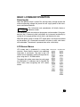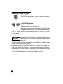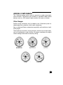
1
IMPORTANT: This User’s Guide outlines the functionality and usage of the
I-Command ™ Integrated Performance System. Before using the I-Command gauges, first read and understand ALL of the supplied product literature, as well as the boat’s user’s guide and outboard’s operator’s guide. This
User’s Guide should be stored onboard for reference.
The photographs, illustrations, and display screens used in this Guide might
not depict actual models, figures, data fields, equipment, or software versions, but are intended as representative views for reference only. The continuing accuracy of this Guide cannot be guaranteed.
† NMEA 2000 is a registered trademark of the National Marine Electronics Association or its
subsidiaries.
The following trademarks are the property of Bombardier Recreational
Products Inc. or its affiliates.
Evinrude ® E-TEC ™
I-Command ™
Johnson ®
S.A.F.E. ™ (Speed Adjusting Failsafe Electronics)
Bombardier Recreational Products Inc.
250 Sea Horse Drive
Waukegan, Illinois 60085 United States
© 2005 BRP US Inc. All rights reserved.
TM, ® Trademarks and registered trademarks of Bombardier Recreational Products Inc. or its affiliates.
1
About this Guide
IMPORTANT: Read this User’s Guide carefully before using the I-Command
gauge series. This User’s Guide should be kept onboard at all times during
operation.
WARNING
For your safety and the safety of others, follow all safety
warnings and recommendations supplied with the boat
and outboard. Do not disregard any of the safety precautions and instructions.
Need Assistance?
For any questions regarding the boat or outboard operation, please refer to
the boat’s user’s guide, or outboard’s operator’s guide for support information.
For questions or problems regarding the I-Command gauge series, please
contact BRP Customer Support at 1-847-689-7090.
2
TABLE OF CONTENTS
INTRODUCTION . . . . . . . . . . . . . . . . 4
Types of Gauges . . . . . . . . . . . . . . 4
BASIC I-COMMAND OPERATION . . 5
Powering Up . . . . . . . . . . . . . . . . . 5
LCD Screen Menus . . . . . . . . . . . . 5
Operating Gauge Buttons . . . . . . . 6
Enter Button . . . . . . . . . . . . . . . . 6
UP/ DOWN Buttons . . . . . . . . . . 6
Exit Function . . . . . . . . . . . . . . . 6
TACHOMETER . . . . . . . . . . . . . . . . . 7
Tachometer LCD Screens . . . . . . . 7
Tachometer System Set-Up . . . . . . 8
LCD Contrast . . . . . . . . . . . . . . . 8
Engine Position . . . . . . . . . . . . . 9
Display Units . . . . . . . . . . . . . . . 9
Fuel Tanks . . . . . . . . . . . . . . . . 10
Trip Log Reset . . . . . . . . . . . . . 12
Engine Data Display . . . . . . . . . 12
Tachometer User Preferences . . . 12
Instrument Backlighting . . . . . . 12
Engine Data . . . . . . . . . . . . . . . . . 13
RPM . . . . . . . . . . . . . . . . . . . . . 13
Engine Coolant Temperature . . 13
Water Pressure . . . . . . . . . . . . 14
Total Engine Hours . . . . . . . . . 14
Fuel Consumption Rate . . . . . . 14
Oil Tank Level . . . . . . . . . . . . . 14
Barometric Pressure . . . . . . . . 14
Engine Status and Alarms . . . . . . 15
Alarm Screens . . . . . . . . . . . . . 16
Clearing Alarms . . . . . . . . . . . . 17
Battery Voltage . . . . . . . . . . . . . . 18
Engine Trim . . . . . . . . . . . . . . . . . 18
Split Screens . . . . . . . . . . . . . . . . 18
SPEEDOMETER . . . . . . . . . . . . . . .
Speedometer LCD Screens . . . . .
Speedometer System Set-up . . . .
LCD Contrast . . . . . . . . . . . . . .
Speed Units . . . . . . . . . . . . . . .
Display Units . . . . . . . . . . . . . .
Speed . . . . . . . . . . . . . . . . . . . . . .
Fuel Level . . . . . . . . . . . . . . . . . . .
Fuel Management . . . . . . . . . . . .
Fuel Consumption Rate . . . . . .
Fuel Economy . . . . . . . . . . . . .
Estimated Fuel Left . . . . . . . . .
Fuel Used . . . . . . . . . . . . . . . . .
Low Fuel Warning . . . . . . . . . .
Water Depth . . . . . . . . . . . . . . . . .
Water Temperature (Sea) . . . . . .
Split Screens . . . . . . . . . . . . . . . .
SPLIT SCREENS . . . . . . . . . . . . . . .
ADDING COMPONENTS . . . . . . . .
Other Gauges . . . . . . . . . . . . . . . .
PRODUCT WARRANTY . . . . . . . . .
19
19
20
20
21
21
21
22
22
23
24
24
24
24
25
25
25
26
27
27
28
3
INTRODUCTION
The I-Command gauge series uses CANBus technology, allowing the sharing of information between different electronic devices which are connected
to an electrical network.
CANBus is a Controller Area Network (“CAN”) pathway (“Bus”), allowing
multiple components to communicate with each other via a central network.
The CANBus collects and manages information from the Evinrude ®
E-TEC ™ outboard through a central processing unit within the tachometer
and then sends that information to the other instrument displays.
The CANBus is also connected to the boat’s larger electronics network—the
NMEA 2000 † Network—which allows it to communicate with other boat
instruments, displays, and engine and accessory functions beyond the
scope of the engine instruments. This information is displayed on I-Command tachometer and speedometer LCD screens.
The I-Command gauge series provides the benefit of sharing more information. Additionally, the wiring system is reduced and simplified, resulting in a
reduction of weight and complexity.
Types of Gauges
The I-Command gauge series is designed to enhance the engine monitoring
capabilities of the boater. Each gauge has a different monitoring function.
Required gauge:
• Tachometer
IMPORTANT: The tachometer is the master gauge. If it is removed or disconnected, all I-Command gauges will stop operating.
Optional gauges:
• Speedometer
• Fuel level
• Oil level
• Water pressure
• Engine trim position
• Voltmeter
4
BASIC I-COMMAND OPERATION
Powering Up
When the ignition switch is turned ON, and the battery voltage reaches the
minimum operating voltage, the power hub will supply power to the instruments and network devices.
The tachometer and speedometer will briefly display a
Welcome screen.
The Welcome screen also displays the program version number. Once powered up, the I-Command system self-checks for instrument functionality by
cycling all of its gauge pointers to their limits, and then back to zero.
When the ignition switch is turned OFF, engine data is no longer transmitted
on the network. All I-Command instruments will return to zero, and alarms
will be disabled. The network is powered down after a brief delay.
LCD Screen Menus
LCD screen data is presented in a menu tree Tachometer / Speedometer
structure. Some display screens have additional
information in sub-menus. The data in the LCD
screen can be viewed by scrolling through the displays using the UP / DOWN buttons.
Throughout this guide, menu trees for each gauge
are displayed as a reference tool to illustrate the
active menu when navigating the LCD screen
menus.
5
Operating Gauge Buttons
¾Enter Button
The ENTER button allows users to access sub-menus,
enter data, and acknowledge alarms.
ENTER
button
¾UP/ DOWN Buttons
The UP and DOWN buttons will scroll data from screen to
screen within the menu or sub-menu.
UP/DOWN
buttons
When searching for data, holding down an UP / DOWN
button will scroll the data at a rate of one line per second.
If an UP / DOWN button is held down longer than five seconds, the scroll
rate will speed up.
¾Exit Function
Certain sub-menus include an exit screen. When at an exit
screen, press ENTER to exit and return to the previous
sub-menu.
To exit a sub-menu without an exit screen, press ENTER and hold for three
seconds until the Main Menu appears.
NOTE: When entering a sub-menu, the last LCD screen viewed before exiting that sub-menu is re-displayed. If a sub-menu was exited using the Exit or
Return screen, that same screen will reappear the next time that sub-menu
is entered. If a sub-menu is entered, and the Exit or Return screen appears,
use the UP / DOWN buttons to scroll to the other data screens.
6
TACHOMETER
The I-Command tachometer is the
master gauge of the I-Command
instrument system. It receives information from all other engine and boat
functions on the network and displays
this information on the dial face and
LCD. The tachometer also passes
information to the speedometer and
other gauges.
Analog
RPM
IMPORTANT: The tachometer is the
master gauge. If it is removed or disconnected, all I-Command gauges will
stop operating.
LCD
screen
UP
button
ENTER
button
DOWN
button
The tachometer displays the engine’s rotations (RPM) through the pointer
and dial face on the upper portion of the instrument. System information and
engine data is presented on the LCD screen in digital form.
Tachometer LCD Screens
The tachometer LCD screen displays a Main Menu
and can be navigated using the UP and DOWN buttons. Sub-menus are accessed with the ENTER button. To exit a sub-menu, press and hold ENTER for
three seconds, or scroll to the sub-menu’s Exit or
Return screen and press ENTER. The Main Menu
LCD screen will reappear.
Main Menu
NOTE: When entering a sub-menu, the last LCD
screen viewed before exiting that sub-menu is redisplayed. Use the UP / DOWN buttons to scroll to the
other data screens.
Available Main Menu screens are:
• System Set-up — See page 8.
• Engine Data — See page 13.
• Engine Status / Alarms — See page 15.
• Battery Voltage — See page 18.
• Engine Trim — See page 18.
• Split Screens — See page 26.
7
Tachometer System Set-Up
The tachometer system set-up allows users to configure engine information output from the tachometer
and adjust different display options to suit user needs.
System Set-Up Menu
Viewing the tachometer system set-up — From the
tachometer Main Menu, use the UP / DOWN buttons
to scroll through LCD screens until the System Set-up
screen appears. Press ENTER. Use the UP / DOWN
buttons to view the set-up features. Press ENTER to
access each feature.
The system set-up controls the following:
• LCD Contrast
• Engine Position
• Display Units
• Fuel Tanks
• Trip Log Reset
• Engine Data ON/OFF
• Exit or Return
¾LCD Contrast
The display contrast of the tachometer can be adjusted to aid in viewing
LCD screens in different lighting conditions.
Setting LCD Contrast — From the System Set-Up screen, scroll to the
Set-Up Contrast display. Press ENTER. “SET” appears in the upper right
corner of the LCD screen. Using the UP / DOWN buttons, select a contrast
value and press ENTER to set the display.
Contrast settings have a range of ten (1 to 10).
NOTE: Only values 3 to 7 can be stored in memory and retained on subsequent power ups.
8
¾Engine Position
IMPORTANT: In multiple engine installations, there is data on the I-Command network for each engine. Each tachometer needs to be set to correspond to the appropriate engine.
Setting an engine position — From the System Set-Up screen, scroll to
the Set-Up Engine Position display. Press ENTER. “SET” appears in the
upper right corner of the LCD screen. Using the UP / DOWN buttons, select
the engine position.
For dual outboards — port = 0, starboard =1
For triple outboards — port = 0, center = 1, starboard = 2
Press ENTER to set the display.
NOTE: If only one outboard is installed, the engine position must be set to
port (0).
¾Display Units
Data can be displayed in English or Metric, depending on user preference.
Setting display units — From the System Set-Up screen, scroll to the
Set-Up Units screen. Press ENTER. “SET” appears in the upper right corner
of the LCD screen. Using the UP / DOWN buttons, select English or Metric.
Press ENTER to set the display.
MEASUREMENT
Barometric
Pressure
Water Pressure
Fuel
Temperature
Water Depth
DISPLAY UNITS TABLE
ENGLISH
METRIC
in. Hg
kPa (kilopascals)
(inches of mercury)
PSI (per square inch)
kPa (kilopascals)
g (U.S. gallons)
l (liters)
°F (Fahrenheit)
°C (Celsius)
ft. (feet)
mtrs (meters)
9
¾Fuel Tanks
NOTE: Setting the fuel tank capacity and calibrating fuel level sensor are
only necessary if an optional speedometer gauge and sensor interface module (SIM) are present.
Tank capacity is entered on the tachometer gauge and is an important component of fuel management. Fuel management is a function of the optional
I-Command speedometer gauge.
When setting fuel tank capacity, it is recommended to factor out a portion as
unuseable fuel.
Unuseable Fuel — Due to the boat’s fuel tank
placement, consider a percentage of the tank’s
fuel capacity as unuseable fuel. This is fuel
that will take up space in the fuel tank, but cannot be reached by the fuel pick-up.
To obtain the most accurate fuel management
readings, tank capacity should be confirmed.
Example — Unuseable Fuel
Fuel pick-up
Useable fuel
capacity
Unuseable
fuel
GOOD — Fuel management based on fuel sensor’s default factory settings.
BETTER — Fuel management based on inputting fuel tank capacity and the
fuel sensor’s default factory settings.
BEST — Fuel management based on inputting fuel tank capacity and performing fuel sensor calibration.
IMPORTANT: It is recommended the fuel tank size be verified. Some tanks
have larger or smaller capacities than posted, and many factors such as
unuseable fuel, tank positioning, mounting, and angle must be considered to
get an accurate capacity. The boat should be oriented in normal operating
position.
Setting fuel tank capacity — Enter the System Set-up screen, and using
the UP / DOWN buttons, scroll to Fuel Tank and press ENTER. The Set-up
Fuel Tanks screen appears. Press the UP / DOWN buttons to toggle
between tank 1 or 2. Press ENTER to select tank 1. “SET” appears in the
upper right corner. Input the tank capacity by continually pressing the UP
button until reaching the desired tank capacity. Press ENTER to set the tank
capacity.
10
Changing fuel tank capacity — Repeat steps to set a different fuel tank
capacity.
For fuel management data on the optional speedometer, see “Fuel Management” on page 22.
Filling the fuel tank and sensor calibration — After setting the tank
capacity, press ENTER to calibrate the fuel sensor. Estimate an amount of
fuel as unuseable (overestimating unuseable fuel will add an additional
safety fuel reserve). This amount must be added to the fuel tank first. After
the unuseable fuel is added, press ENTER. The gauge enters an empty
value. The unuseable fuel cannot be reached by the fuel pick-up, and the
sensor sends an empty reading. The gauge then prompts the user to fill tank
1 to 50%.
Once fuel tank 1 is filled 50%, press ENTER. The gauge waits for a response,
then prompts the user to fill tank 1 to 100%. Press ENTER to close the fuel
tank calibration menu.
Repeat process for additional fuel tanks.
Fuel sensor calibration example — If the Example — 100 Gallon Fuel Tank
fuel tank has a posted capacity of 100 gallons,
Fuel pick-up
unuseable fuel could be estimated to be 10
90 gallons
gallons, leaving a useable fuel capacity of 90
useable fuel
45
capacity
gallons
gallons. Half of 90 gallons is 45 gallons.
For an empty 100-gallon fuel tank, 10 gallons
of unuseable fuel is added, an empty value is
registered, then 45 additional gallons of fuel
must be added to reach 50% of useable fuel
capacity.
90 ÷ 2 = 45
10 gallons
(unuseable)
added first
If an error in the filling procedure occurs, the fuel sensor can be re-set.
Re-setting fuel sensor — Turn the key OFF. Press and hold the UP,
ENTER, and DOWN buttons. Turn the key ON. The Utilities screen appears.
Release the buttons. Using the UP / DOWN buttons, select the fuel tank
sensor to be reset. Press ENTER. The fuel sensor returns to its default settings. The default sensor settings do not reflect accurate fuel level, and the
sensor must be recalibrated at next re-fueling. Use the UP / DOWN buttons
to select additional tanks. After re-setting, scroll to the exit screen. Press
ENTER exit the Utilities screen.
11
¾Trip Log Reset
The trip log is the cumulative total number of gallons (or liters) of fuel used
during each boat outing. Fuel usage can be reset to zero by resetting the trip
log. The trip log (fuel usage total) can be viewed on the Fuel Used screen of
the optional I-Command speedometer gauge (See “Fuel Used” on page 24).
Re-setting trip log — From the System Set-Up screen, scroll to the Trip
Log Reset display. Press ENTER to reset the trip log. This resets the Fuel
Used screen of the speedometer (see “Fuel Used” on page 24).
¾Engine Data Display (ON/OFF)
LCD screens can be turned ON or OFF to “skip” screens that do not display
data or are not applicable. When a screen is turned off, the LCD screen will
not appear on the engine data menu. (For a list of the available Engine Data
screens, see “Engine Data” on page 13.)
Turning a screen ON / OFF — From the System Set-up screen, select the
Set-up Engine Data screen by pressing ENTER.
Scroll through the Engine Data screens by pressing UP / DOWN buttons. If
the data display is turned on, “ON” appears in the upper right corner. When
the desired Engine Data screen appears, press ENTER. “SET” appears in
the upper right corner. Using the UP / DOWN button, select ON or OFF.
Press ENTER to set the display.
Tachometer User Preferences
¾Instrument Backlighting
Each I-Command instrument gauge face is red backlighted for increased
low-light visibility. The brightness of the lighting can be adjusted to user preference. Setting the tachometer backlighting will adjust all other gauges on
the I-Command system. If another tachometer is present, it can be adjusted
independently.
Turning backlighting ON / OFF — Press and buttons simultaneously.
Adjusting backlighting — With backlighting on, press UP or DOWN button
to adjust the brightness. Once desired brightness is selected, press UP and
DOWN buttons simultaneously again to set the adjustment.
12
Engine Data
The information collected by the network communicates real time data to the I-Command tachometer.
This information is displayed on the Engine Data LCD
screen. The default engine data is displayed on the
Engine Data screen of the Main Menu.
Engine Data Menu
Changing default engine data display — To change
the default engine data display, scroll to the Engine
Data screen. Press ENTER. The Engine Data bar at
the top of the screen appears in reverse color. Using
the UP / DOWN buttons, view the data. Press and
hold ENTER for three seconds to set a specific engine
data screen as the default data to be displayed on the
Main Menu.
After scrolling through the entire list, an exit screen will
display. Press ENTER to return to the Main Menu.
The available Engine Data sub-screens are:
• RPM
• Engine Coolant Temperature
• Water Pressure
• Total Engine Hours
• Fuel Consumption Rate
• Oil Tank Level
• Barometric Pressure
• Exit or Return
¾RPM
RPM is engine revolutions per minute.
¾Engine Coolant Temperature
The coolant temperature is the temperature of the water circulating through
the engine.
13
¾Water Pressure
The pressure displayed is the current pressure of water moving through the
engine.
NOTE: Water pressure data capability requires an accessory water pressure transducer kit, P/N 5006214. If the kit is not installed, the Water Pressure screen should be turned OFF. (To turn off a screen display, see “Engine
Data Display (ON/OFF)” on page 12.)
¾Total Engine Hours
The total engine hours are the running hours the engine has accumulated
since its first start. The display units will be in hours and tenths of hours.
¾Fuel Consumption Rate
The fuel consumption rate is current fuel consumption in gallons (or liters)
per hour.
For additional fuel management capabilities on the optional speedometer,
see “Fuel Management” on page 22.)
¾Oil Tank Level
The oil tank level displays the level of oil in the oil reservoir. The amount displayed is in percent.
NOTE: The oil tank level display requires an accessory oil tank sender. See
an authorized Dealer. By default, the Oil Tank Level screen is turned OFF. If
the oil tank sender is installed, the oil tank level display must be turned ON
to view data. (To turn on a screen display, see “Engine Data Display (ON/
OFF)” on page 12.)
¾Barometric Pressure
The barometric pressure shows the current atmospheric pressure.
14
Engine Status and Alarms
Alarms appear on the Engine Status screen and alert
the user of an operating condition that requires action.
If an alarm occurs, the Engine Status screen will
immediately display the active alarm to indicate what
the operating fault is.
Engine Status Menu
IMPORTANT: An alarm will take priority and override
any other LCD screen data displays.
Once active, the alarm screen will flash between standard and reverse screen color. Additionally, the two
warning LEDs in the tachometer (one on each side of
the LCD screen) will illuminate red, and the alarm
buzzer will sound.
There may be more than one alarm message at the same
time. The number displayed in the upper right-hand corner
on the active alarm LCD screen advises how many alarms
are active.
(For typical alarm screens, see “Alarm Screens” on page 16; for instructions
on disabling alarms, see “Clearing Alarms” on page 17.)
15
¾Alarm Screens
The following alarms require action by the operator. Check the outboard’s
operator’s guide to determine the cause of the alarm and any actions
required to correct the situation.
Overheat –
RPM Reduction
Overheat –
Engine Shutdown
An overheat condition exists.
S.A.F.E. ™ mode activates. Engine
RPM will reduce, and boat speed
will slow until cooling is restored.
No Oil –
RPM Reduction
A critical overheat condition exists.
The engine will shutdown and will
not restart until it has cooled.
No Oil –
Engine Shutdown
An oil delivery problem exists.
S.A.F.E. activates. Engine RPM will
reduce, and boat speed will slow
until oil delivery is restored.
Low Battery –
A prolonged oil delivery problem
exists. The engine will shutdown
and will not run for an extended
period until oil delivery is restored.
Low Oil –
Check Oil Supply
The battery is low. Starter motor
may not operate, and outboard
may not start.
The oil tank is low. Refill the oil tank
immediately.
16
The following alarms require Dealer inspection. It is important that an authorized Dealer inspect the outboard and perform any necessary service.
Unsafe operating conditions can exist, and outboard damage may result if
alarms requiring Dealer service are ignored.
Sensor –
Service soon
Injector –
Service soon
There is a problem with one of the
outboard’s sensors. Seek service
from an authorized Dealer upon
return to port.
Water in Fuel –
Service soon
There is a problem with one of the
outboard’s fuel injectors. Seek service from an authorized Dealer
upon return to port.
RPM Reduction –
Service soon
There is water in the fuel tank or
fuel delivery system. Seek service
from an authorized Dealer upon
return to port.
Ignition –
Service soon
The engine RPM has been reduced
to avoid outboard damage due to
an unsafe operating condition.
Seek service.
Winterization –
See guide
The outboard’s ignition system may
be faulty and requires inspection.
Seek service from an authorized
Dealer upon return to port.
The winterization mode has been
activated. Refer to the outboard’s
operator’s guide.
¾Clearing Alarms
Acknowledge the alarm by pressing ENTER on the tachometer. Once all
alarms have been acknowledged, the alarm buzzer will stop, and the LCD
screen will clear. The warning LEDs will remain illuminated until the operating fault is corrected.
If there is a loss of instrument communications, all affected gauges will
return the pointers to zero. The LCD screens will show a blank or zero value
for data. Monitoring data will not function until instrument communication is
corrected. See an authorized Dealer immediately.
17
Battery Voltage
From the Main Menu screen, scroll to the Battery Voltage display.
The battery voltage range is 0 to 18 volts, measured in
0.1 volt increments. In multiple engine applications,
each tachometer will display the system voltage of its
respective engine.
Engine Trim
From the Main Menu screen, scroll to the Engine Trim
display.
The engine trim range is 0 to 100 percent, measured
in 1 percent increments.
NOTE: Engine tilt is not displayed.
Split Screens
Split screens enable one LCD screen to display two data
sources. See “Split Screens” on page 26 for information
about accessing and setting LCD split screens on both
tachometer and speedometer gauges.
18
Main Menu
SPEEDOMETER
The optional I-Command speedometer provides valuable data regarding
boat speed and other boat related
functions.
Speed readings require a GPS or paddlewheel. Fuel management requires
a sensor interface module (SIM).
Analog
speed
See an authorized Dealer for accessories.
LCD
screen
UP
button
ENTER
button
DOWN
button
The speedometer displays the boat’s
speed through the pointer and dial
face on the upper portion of the instrument. If desired, the speedometer will also display the speed digitally on the
LCD screen. Optional fuel management is also displayed by the speedometer.
Speedometer LCD Screens
The speedometer LCD screen displays a Main Menu
and can be navigated using the UP and DOWN buttons. Sub-menus are accessed with the ENTER button. To exit a sub-menu, press and hold ENTER for
three seconds. The Main Menu screen will reappear.
Main Menu
NOTE: When entering a sub-menu, the last LCD
screen viewed before exiting that sub-menu is redisplayed. Use the UP / DOWN buttons to scroll to the
other data screens.
Available Main Menu screens are:
• System Set-Up — See page 20.
• Speed — See page 21.
• Fuel Level — See page 22.
• Fuel Management — See page 22.
• Water Depth — See page 25.
• Sea Water Temperature — See page 25.
• Split Screens — See page 26.
19
Speedometer System Set-up
The speedometer system set-up allows users to configure engine information output from the speedometer and adjust different display options to suit user
needs.
System Set-Up Menu
Viewing the speedometer system set-up — From
the speedometer Main Menu, use the UP / DOWN
buttons to scroll through the LCD screens until the
System Set-up screen appears. Press ENTER. Use
the UP / DOWN buttons to view the set-up features.
Press ENTER to access each feature.
The system set-up controls the following:
• LCD Contrast
• Speed Units
• Display Units
¾LCD Contrast
The display contrast of the speedometer can be adjusted to aid in viewing
LCD screens in different lighting conditions.
Setting LCD Contrast — From the System Set-Up screen, scroll to the
Set-Up Contrast display. Press ENTER. “SET” appears in the upper right
corner of the LCD screen. Using the UP / DOWN buttons, select a contrast
value and press ENTER to set the display.
Contrast settings have a range of ten (1 to 10).
NOTE: Only values 3 to 7 can be stored in memory and retained on subsequent power ups.
Adjusting backlighting — Speedometer gauge backlighting is set by the
tachometer gauge. (To adjust the backlighting, see “Instrument Backlighting”
on page 12.)
20
¾Speed Units
If the speedometer is set for English display units, the speed units display
will default to miles per hour (mph). Speed displays can also be set to knots
(kn), or kilometers per hour (kph).
Changing speed units display — From the System Set-Up screen, scroll
to the Set-Up Speed display. Press ENTER. Using the UP / DOWN buttons,
select a display unit. Press ENTER to set the unit.
¾Display Units
Data can be displayed in English or Metric, depending on user preference.
Setting display units — From the System Set-Up screen, scroll to the
Set-Up Units screen. Press ENTER. “SET” appears in the upper right corner
of the LCD screen. Using the UP / DOWN buttons, select English or Metric.
Press ENTER to set the display. (For a list of the display units, see the “Display Units Table” on page 9.)
Speed
Boat speed is measured as speed over water, speed
over ground, or both.
Speed Menu
Speed over water (SOW) requires a speedometer
pick-up paddle wheel. The speed is measured by calculating the rate of water passing under the boat.
Speed over ground (SOG) requires a GPS antenna.
The speed is measured by calculating the movement
of the boat in relation to satellite signals.
See an authorized Dealer for accessories.
Changing Speed Measurement — To change the
speed display, scroll to the Speed screen. Press
ENTER. The Speed bar at the top of the Speed screen
appears in reverse color, and the speed measurement
is displayed. Using the UP / DOWN button, select Over Water or Over
Ground. Press and hold ENTER for three seconds to set the display. The
Main Menu appears after the speed measurement is set.
21
Fuel Level
The Fuel Level screen displays in percent the amount
of fuel in the selected fuel tank. The default fuel tank is
displayed on the Fuel Level screen of the Main Menu.
Fuel Level Menu
Changing default fuel tank — To change the default
fuel tank, scroll to the Fuel Level screen. Press
ENTER. The Fuel Level bar at the top of the screen
appears in reverse color, and fuel tank 1 is displayed.
Using the UP / DOWN button, select tank 2. Press
and hold ENTER for three seconds to set the display.
The default fuel tank is set and will appear on the Fuel
Level screen of the Main Menu.
At the Fuel Level screen, press the DOWN button to
reach the exit screen. Press ENTER to return to the
Main Menu.
Fuel Management
The Fuel Management screen is designed to give Fuel Management Menu
users an approximate representation of fuel usage
and fuel level. Due to various factors such as fuel system configuration, fuel tank size and shape, and boating conditions, the fuel gauge is only a guide to fuel
management and cannot be relied upon to display an
exact reading. Return to port immediately if the low
fuel alarm is activated.
The I-Command system can monitor fuel level and
consumption. Fuel management is an optional feature, and requires the installation of an I-Command
speedometer and a sensor interface module (SIM). It
is recommended these components be installed by an
authorized Dealer.
To improve fuel management accuracy, calibrate all fuel tank level sensors
so all information can be collected. See “Fuel Tanks” on page 10 for detailed
instructions on fuel tank calibration.
22
IMPORTANT: Always confirm fuel level before boating, and check fuel level
often. The fuel level gauge is designed to be a reference for fuel level during
usage; however, it is recommended boat operators apply the fuel usage
principle of 1/3 fuel to destination, 1/3 fuel to return to port, and 1/3 fuel for
reserve.
WARNING
Running out of fuel could cause the operator of the boat
to have diminished or no control of the vessel, presenting a risk of personal injury to the operator, passengers,
and people who are nearby.
Viewing Fuel Management screens — From the Main Menu, scroll to the
Fuel Management screen. Press ENTER and use the UP / DOWN buttons
to scroll through the screens.
Selecting fuel management display — To select the fuel management display, scroll to the Fuel Management screen. Press ENTER. The Fuel Management bar at the top of the screen appears in reverse color. Using the
UP / DOWN buttons, view the data. Press and hold ENTER for three seconds to select a data display to be shown on the Main Menu.
¾About Fuel Management Displays
The fuel level displays—both digital and analog—receive an update from
the electronics every 10 seconds. The programming is designed to filter out
rapid fluctuations in the fuel level when traveling at high speeds, or on rough
waters, offering a consistent, stable representation of the fuel level.
¾Fuel Consumption Rate
Fuel consumption rate is up-to-the-minute fuel consumption in gallons (or
liters) per hour.
For multiple outboards, each tachometer displays the consumption rate of
the individual outboard that tachometer is monitoring. The speedometer displays the combined fuel consumption rate of all outboards.
NOTE: The fuel consumption rate can also be viewed on the tachometer.
See “Fuel Consumption Rate” on page 14.
23
IMPORTANT: Fuel Economy, Estimated Fuel Left and Fuel Used screens all
require the installation of an I-Command speedometer and a sensor interface module (SIM). It is recommended these components be installed by an
authorized Dealer.
¾Fuel Economy
IMPORTANT: A GPS measuring speed over ground is required for fuel
economy readings. See an authorized Dealer.
Economy can presented as:
• Miles per gallon; (m/g)
• Nautical miles per gallon (nm/g); or
• Kilometers per liter (km/ltr).
¾Estimated Fuel Left
Estimated fuel left is the amount of fuel available for use. There is a small
percentage of unuseable fuel in the fuel tank. The fuel tank must be calibrated for an accurate estimate of the fuel left. (See “Fuel Tanks” on
page 10.)
¾Fuel Used
Fuel used is the total cumulative amount of fuel used by the outboard. When
operating multiple outboards, the fuel used is the total amount of fuel used
by all outboards. Additionally, fuel used is the total amount of fuel used from
multiple fuel tanks (if installed). The fuel used can be reset by doing a trip
log reset. (See “Trip Log Reset” on page 12.)
¾Low Fuel Warning
When the fuel level in a fuel tank is 10% full (90% empty), a low fuel alarm
will display on the Engine Status screen, and the alarm buzzer will sound.
Acknowledge the alarm by pressing ENTER. The low fuel alarm will clear
once the fuel tank is refilled.
WARNING
Running out of fuel could cause the operator of the boat
to have diminished or no control of the vessel, presenting a risk of personal injury to the operator, passengers,
and people who are nearby.
24
Water Depth
IMPORTANT: A transducer (enabling depth and temperature) or triducer (enabling depth, temperature,
and speed) is required for depth display. See an
authorized Dealer.
From the Main Menu screen, scroll to the Depth display.
Main Menu
The Water Depth screen shows the depth of the water
directly under the boat.
The depth range is measured in feet or meters.
WARNING
Do not use depth reading as a navigational aid
to prevent collision, grounding, boat damage,
or personal injury. When boat is moving, water
depth may change too quickly to allow time to
react. Operate at slow speeds if shallow water
or submerged objects are suspected.
Water Temperature (Sea)
IMPORTANT: A transducer (enabling depth and temperature) or triducer (enabling depth, temperature,
and speed) is required for temperature display. See an
authorized Dealer.
From the Main Menu screen, scroll to the Water Temperature display.
The Water Temperature screen displays the sea water temperature.
The temperature is measured in Fahrenheit (°F) or Celsius (°C).
Split Screens
Split screens enable one LCD screen to display two data
sources. See “Split Screens” on page 26 for information
about accessing and setting LCD split screens on both
tachometer and speedometer gauges.
25
SPLIT SCREENS
A split screen allows the operator to view two separate Tachometer Speedometer
data displays at the same time on one LCD screen.
Viewing split screen data — From the Main Menu of
either gauge, press the DOWN button until the Split
Screen menu appears. Press ENTER. The bar at the
top of the split screen appears in reverse color. The
display can now be customized to output any data
combination desired. The UP button will scroll the
available data displays on the left side of the screen.
The DOWN button will scroll the available data displays on the right side of the screen. Once the desired
displays appear, press ENTER to set the combination.
Tachometer data displays available in split screen
mode:
•
•
•
•
Barometric Pressure
Engine Temperature
Fuel Consumption Rate
Oil Tank Level
•
•
•
•
RPM
Engine Trim
Battery Voltage
Water Pressure
Speedometer data displays available in split screen mode:
•
•
•
•
Depth
Estimated Fuel Left
Fuel Consumption Rate
Fuel Economy
26
• Fuel Level (Tank 1 or 2)
• Speed (SOG or SOW)
• Water Temperature
ADDING COMPONENTS
The I-Command gauge series allows for expansion to other components
and instruments. The network gives flexibility to add NMEA 2000 certified
devices, such as a GPS antenna, depth sounder, fish locator, or triducer.
Other Gauges
Smaller analog instruments may be added to the I-Command system for
added engine data, protection, and for quick referencing.
See an authorized Dealer to determine compatibility and installation of additional gauges.
These optional instruments are plug-and-play, feature easy-to-read scales,
and are backlighted for night viewing. All gauges complement the digital
screen readings and include all necessary wiring.
Oil Tank Level
Water Pressure
Voltage
Fuel Level
Engine Trim
27
PRODUCT WARRANTY
BRP LIMITED WARRANTY FOR EVINRUDE/JOHNSON GENUINE PARTS
AND ACCESSORIES SOLD IN THE UNITED STATES AND CANADA
Bombardier Recreational Products Inc. (“BRP”) warrants its Evinrude ®/Johnson ® Genuine
Parts and accessories (“Product”) sold by authorized Evinrude or Johnson dealers in the fifty
United States and Canada from defects in material or workmanship for the period and under
the conditions described below. This limited warranty does not apply to Products not bearing
the Evinrude or Johnson trademarks that are made by other manufacturers. This limited warranty extends to the original retail purchaser only (“Purchaser”) and is not transferable to any
subsequent owner. This warranty is available only on Products purchased as new and
unused from a dealer authorized to distribute the Products in the country in which the sale
occurred (“Dealer”).
Powerhead assemblies are warranted for a period of SIX (6) CONSECUTIVE MONTHS from
the date of purchase. All other Products are warranted for a period of TWELVE (12) CONSECUTIVE MONTHS from the date of purchase.
Purchaser must bring the Product, including any defective part therein, and proof of purchase
of the Product (original bill of sale) to Dealer promptly after the appearance of the defect and,
in any event, within the warranty period. Purchaser must sign the repair/work order prior to
repair to validate warranty coverage and must provide BRP/Dealer with a reasonable opportunity to repair/replace the defective part. All replaced parts become the property of BRP.
BRP’s obligations under this warranty are limited to, at its sole discretion, repairing or replacing parts of Product found to be defective in material or workmanship, in BRP’s reasonable
judgment. Repair or replacement of parts will be without charge for parts and labor, at any
authorized Dealer. No claim of breach of warranty shall be cause for cancellation or rescission of the sale of Product to Purchaser. BRP reserves the right to improve, modify or change
Products without assuming any obligation to modify Products previously manufactured. If
warranty service is required outside of the fifty United States or Canada, Purchaser will bear
responsibility for any additional charges due to local practices and conditions including, but
not limited to, freight, insurance, taxes, license fees, import duties, and any financial charges
levied by governments, states, territories and agencies.
28
The following are not warranted under any circumstances: (a) normal wear and tear; (b)
routine maintenance items including, but not limited to, adjustments, oil changes, water
pumps, carburetor maintenance, spark plug replacements, etc.; (c) cosmetic damage or paint
changes due to exposure to the elements; or (d) damage caused by: improper or lack of
installation, maintenance, winterization and/or storage; failure to follow the procedures and
recommendations in the Operator’s Guide; removal of parts, improper repairs, service, maintenance, or modification; use of parts or accessories not manufactured or approved by BRP
that are either incompatible with Product or adversely affect its operation, performance, or
durability; repairs done by anyone, including Purchaser, other than an authorized Dealer;
abuse, misuse, abnormal use, neglect, racing, improper operation or operation of Product in
a manner inconsistent with the Operator’s Guide; external damage, accident, submersion,
water ingestion, fire, theft, vandalism or act of God; operation with fuels, oils or lubricants not
suitable for use with Product (see Operator’s Guide); rust or corrosion; or cooling system
blockage by foreign material.
This warranty will be voided in its entirety and rendered null and void: (a) where Product has
been altered or modified in such a way so as to adversely affect its operation, performance or
durability, or has been altered or modified to change its intended use; or (b) where Product is
or has been used for racing or any other competitive activity, at any point.
ALL WARRANTIES, EXPRESSED OR IMPLIED, INCLUDING WITHOUT LIMITATION ANY
WARRANTY OF MERCHANTABILITY OR FITNESS FOR A PARTICULAR PURPOSE ARE
LIMITED IN DURATION TO THE LIFE OF THIS EXPRESS LIMITED WARRANTY. ALL
INCIDENTAL, CONSEQUENTIAL, DIRECT, INDIRECT OR OTHER DAMAGES OF ANY
KIND ARE EXCLUDED FROM COVERAGE UNDER THIS WARRANTY INCLUDING, BUT
NOT LIMITED TO: expense for gasoline, expense for transporting Product to and from
Dealer, removal of Product from a boat and reinstallation, mechanic’s travel time, in-and-out
of water charges, slip or dock fees, trailering or towing, storage, telephone, cell phone, fax or
telegram charges, rental of a like or replacement Product or boat during warranty services or
down time, taxi, travel, lodging, loss of or damage to personal property, inconvenience, cost
of insurance coverage, loan payments, loss of time, income, revenue, profits, enjoyment or
use of Product.
SOME JURISDICTIONS DO NOT ALLOW FOR THE DISCLAIMERS, LIMITATIONS OF
INCIDENTAL OR CONSEQUENTIAL DAMAGES, OR OTHER EXCLUSIONS IDENTIFIED
ABOVE. AS A RESULT, THEY MAY NOT APPLY TO YOU. THIS WARRANTY GIVES YOU
SPECIFIC RIGHTS, AND YOU MAY ALSO HAVE OTHER LEGAL RIGHTS THAT MAY
VARY FROM JURISDICTION TO JURISDICTION.
No distributor, Dealer or any other person is authorized to make any affirmation, representation or warranty regarding Product other than those contained in this limited warranty and, if
made, shall not be enforceable against BRP. BRP reserves the right to modify this warranty
at any time, being understood that such modification will not alter the warranty conditions
applicable to the Products sold while this warranty is in effect. For assistance, please contact
BRP US Inc. Customer Support Services, 250 Sea Horse Drive, Waukegan, IL, 60085,
1-847-689-7090 or visit www.brp.com.
29
For Products sold outside the fifty United States and Canada, the BRP Limited Warranty for
Evinrude/Johnson Genuine Parts and Accessories Sold in the United States and Canada
(“Limited Warranty”) applies, except it is modified as follows:
• The Limited Warranty applies only to Products purchased as new and unused from a distributor or dealer authorized to distribute Products in the country in which the sale occurred.
• Products purchased for commercial use, or used commercially at any time during the warranty period, are warranted for SIX (6) CONSECUTIVE MONTHS from the date of purchase. Product is used commercially when it is used in connection with any work or
employment that generates income, during any part of the warranty period. Product is also
used commercially when, at any point during the warranty period, it is installed on a boat
that has commercial tags or is licensed for commercial use.
• If warranty service is required outside of the country of original sale, Purchaser bears
responsibility for any and all charges due to local practices and conditions that exceed or
are in addition to customary charges in the country of sale, such as, but not limited to,
freight, insurance, taxes, license fees, import duties, and any financial charges levied by
governments, states, territories and agencies.
• For assistance, please contact BRP US Inc. Customer Support Services, 250 Sea Horse
Drive, Waukegan, Illinois, 60085, 1-847-689-7090, or the affiliate of BRP Inc. where the
Product was sold to the retail Purchaser.
No other change to the Limited Warranty shall be made or implied.
Effective as of December 1, 2001.
30