1
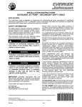
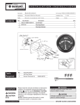
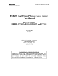
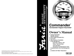
SAFETY INFORMATION
This booklet is written for qualified, factory-trained
technicians who are already familiar with the use
of Evinrude ®/Johnson ® Special Tools. This booklet
is not a substitute for work experience. It is an
organized guide for installation of the ICON gauge
system.
This booklet uses the following signal words identifying important safety messages.
A DANGER
Indicates an imminently hazardous situation
which, if not avoided, WILL result in death
or serious injury.
A WARNING
Indicates a potentially hazardous situation
which, if not avoided, CAN result in severe
injury or death.
A CAUTION
Indicates a potentially hazardous situation
which, if not avoided, MAY result in minor or
moderate personal injury or property damage. It also may be used to alert against
unsafe practices.
IMPORTANT: Identifies information that will help
prevent damage to machinery and appears next
to information that controls correct assembly and
operation of the product.
These safety alert signal words mean:
ATTENTION!
BECOME ALERT!
YOUR SAFETY IS INVOLVED!
Always follow common shop safety practices. If
you have not had training related to common shop
safety practices, you should do so to protect yourself, as well as the people around you.
It is understood that this booklet may be translated into other languages. In the event of any discrepancy, the English version shall prevail.
DO NOT perform any installation until you have
read the instructions and checked the pictures
relating to the installation procedures.
Be careful, and never rush or guess a service procedure. Human error is caused by many factors:
carelessness, fatigue, overload, preoccupation,
unfamiliarity with the product, and drugs and alcohol use, to name a few. Damage to a boat and
outboard can be fixed in a short period of time, but
injury or death has a lasting effect.
When replacement parts are required, use
Evinrude/Johnson Genuine Parts or arts with
equivalent characteristics, including type, strength
and material. Using substandard parts could result
in injury or product malfunction.
Torque wrench tightening specifications must be
strictly followed. Replace any locking fastener
(locknut or patch screw) if its locking feature
becomes weak. Definite resistance to turning
must be felt when reusing a locking fastener. If
replacement is specified or required because the
locking fastener has become weak, use only
authorized Evinrude/Johnson Genuine Parts.
If you use procedures or service tools that are not
recommended in this instruction booklet, YOU
ALONE must decide if your actions might injure
people or damage the outboard.
The following trademarks are the property of Bombardier Recreational Products Inc. or its affiliates.
Evinrude ®
I-Command ™
Evinrude ® E-TEC ®
Johnson ®
† NMEA 2000 is a registered trademark of the National Marine Electronics Association or its subsidiaries.
† DeviceNet is a registered trademark ODVA.
† Deutsch is a registered trademark of The Deutsch Company.
© 2011 BRP US Inc. All rights reserved.
TM, ®, and the BRP logo are registered trademarks of Bombardier Recreational Products Inc. or its affiliates.
Before working on any part of the outboard, read the following SAFETY information.
A DANGER
Contact with a rotating propeller is likely to result in serious injury or death. Assure the
engine and prop area is clear of people and objects before starting engine or operating boat.
Do not allow anyone near a propeller, even when the engine is off. Blades can be sharp and
the propeller can continue to turn even after the engine is off. Remove propeller before servicing and when running the outboard on a flushing device.
DO NOT run the engine indoors or without adequate ventilation or permit exhaust fumes to
accumulate in confined areas. Engine exhaust contains carbon monoxide which, if inhaled,
can cause serious brain damage or death.
A WARNING
Wear safety glasses to avoid personal injury, and set compressed air to less than 25 psi (172
kPa).
The motor cover and flywheel cover are machinery guards. Use caution when conducting
tests on running outboards. DO NOT wear jewelry or loose clothing. Keep hair, hands, and
clothing away from rotating parts.
During service, the outboard may drop unexpectedly. Avoid personal injury; always support
the outboard’s weight with a suitable hoist or the tilt support bracket during service.
To prevent accidental starting while servicing, disconnect the battery cables at the battery.
Twist and remove all spark plug leads.
The electrical system presents a serious shock hazard. DO NOT handle primary or secondary
ignition components while outboard is running or flywheel is turning.
Gasoline is extremely flammable and highly explosive under certain conditions. Use caution
when working on any part of the fuel system.
Protect against hazardous fuel spray. Before starting any fuel system service, carefully
relieve fuel system pressure.
Do not smoke, or allow open flames or sparks, or use electrical devices such as cellular
phones in the vicinity of a fuel leak or while fueling.
Keep all electrical connections clean, tight, and insulated to prevent shorting or arcing and
causing an explosion.
Always work in a well ventilated area.
Replace any locking fastener (locknut or patch screw) if its locking feature becomes weak.
Definite resistance to tightening must be felt when reusing a locking fastener. If replacement
is indicated, use only authorized replacement or equivalent.
2
ICON GAUGE INSTALLATION GUIDE
SAFETY INFORMATION
ICON Gauge Installation Guide
3
ICON GAUGE INSTALLATION GUIDE
TABLE OF CONTENTS
TABLE OF CONTENTS
ICON Gauge Kits . . . . . . . . . . . . . . . . . . . . . . . . . . . . . . . . . . . . . . . . . . . . . . . . . . . . . . . . . . . . . . . . . . . . 5
5 in. (127 mm) Pro Series Tachometer and Speedometer . . . . . . . . . . . . . . . . . . . . . . . . . . . . . . . . . . . . .
3.5 in. (89 mm) Pro Series Tachometer and Speedometer . . . . . . . . . . . . . . . . . . . . . . . . . . . . . . . . . . . .
5 in. (127 mm) 3-n-1 Series . . . . . . . . . . . . . . . . . . . . . . . . . . . . . . . . . . . . . . . . . . . . . . . . . . . . . . . . . . . .
3.5 in. (89 mm) Basic Series . . . . . . . . . . . . . . . . . . . . . . . . . . . . . . . . . . . . . . . . . . . . . . . . . . . . . . . . . . . .
2 in. (51 mm) . . . . . . . . . . . . . . . . . . . . . . . . . . . . . . . . . . . . . . . . . . . . . . . . . . . . . . . . . . . . . . . . . . . . . . . .
5
5
6
6
7
Network Connections . . . . . . . . . . . . . . . . . . . . . . . . . . . . . . . . . . . . . . . . . . . . . . . . . . . . . . . . . . . . . . . . 8
Multiple Gauges . . . . . . . . . . . . . . . . . . . . . . . . . . . . . . . . . . . . . . . . . . . . . . . . . . . . . . . . . . . . . . . . . . . . .
Warning Horns . . . . . . . . . . . . . . . . . . . . . . . . . . . . . . . . . . . . . . . . . . . . . . . . . . . . . . . . . . . . . . . . . . . . . .
Pressure Ports . . . . . . . . . . . . . . . . . . . . . . . . . . . . . . . . . . . . . . . . . . . . . . . . . . . . . . . . . . . . . . . . . . . . . .
Network Power and Grounds . . . . . . . . . . . . . . . . . . . . . . . . . . . . . . . . . . . . . . . . . . . . . . . . . . . . . . . . . . .
Network Connectors . . . . . . . . . . . . . . . . . . . . . . . . . . . . . . . . . . . . . . . . . . . . . . . . . . . . . . . . . . . . . . . . . .
8
8
8
8
8
Network Reference Diagrams . . . . . . . . . . . . . . . . . . . . . . . . . . . . . . . . . . . . . . . . . . . . . . . . . . . . . . . . . . 9
Electronic Remote Control Network . . . . . . . . . . . . . . . . . . . . . . . . . . . . . . . . . . . . . . . . . . . . . . . . . . . . . . 9
Mechanical Remote Control Network with the I-Command Ignition and Trim/Tilt Harness . . . . . . . . . . . 10
Mechanical Remote Control Network with the SystemCheck Harness . . . . . . . . . . . . . . . . . . . . . . . . . . 11
Gauge Dimensions . . . . . . . . . . . . . . . . . . . . . . . . . . . . . . . . . . . . . . . . . . . . . . . . . . . . . . . . . . . . . . . . . 12
Drilled Hole Sizes . . . . . . . . . . . . . . . . . . . . . . . . . . . . . . . . . . . . . . . . . . . . . . . . . . . . . . . . . . . . . . . . . . . 12
Instrument Panel Clearances . . . . . . . . . . . . . . . . . . . . . . . . . . . . . . . . . . . . . . . . . . . . . . . . . . . . . . . . . 13
Gauge Spacing (center to center) . . . . . . . . . . . . . . . . . . . . . . . . . . . . . . . . . . . . . . . . . . . . . . . . . . . . . . . 13
Instrument Panel Thickness . . . . . . . . . . . . . . . . . . . . . . . . . . . . . . . . . . . . . . . . . . . . . . . . . . . . . . . . . . . 13
Hole Sizes . . . . . . . . . . . . . . . . . . . . . . . . . . . . . . . . . . . . . . . . . . . . . . . . . . . . . . . . . . . . . . . . . . . . . . . . . 13
Fastening the Gauge . . . . . . . . . . . . . . . . . . . . . . . . . . . . . . . . . . . . . . . . . . . . . . . . . . . . . . . . . . . . . . . . 13
Gauge Back Clamp Kits . . . . . . . . . . . . . . . . . . . . . . . . . . . . . . . . . . . . . . . . . . . . . . . . . . . . . . . . . . . . . . 13
Weather Plugs . . . . . . . . . . . . . . . . . . . . . . . . . . . . . . . . . . . . . . . . . . . . . . . . . . . . . . . . . . . . . . . . . . . . . 14
Tachometer Harness . . . . . . . . . . . . . . . . . . . . . . . . . . . . . . . . . . . . . . . . . . . . . . . . . . . . . . . . . . . . . . . . 15
Tachometer Harness 12 Socket Plug Connector Detail . . . . . . . . . . . . . . . . . . . . . . . . . . . . . . . . . . . . . . 16
Tachometer Harness NMEA 2000 Connector Detail . . . . . . . . . . . . . . . . . . . . . . . . . . . . . . . . . . . . . . . . 16
Tachometer Harness Gauge Buss Connector Detail . . . . . . . . . . . . . . . . . . . . . . . . . . . . . . . . . . . . . . . . 16
Tachometer to speedometer harness connection . . . . . . . . . . . . . . . . . . . . . . . . . . . . . . . . . . . . . . . . . . 16
Tachometer harness connection to 2 in. gauge . . . . . . . . . . . . . . . . . . . . . . . . . . . . . . . . . . . . . . . . . . . . 17
Tachometer Harness Power Connection and Analog Inputs . . . . . . . . . . . . . . . . . . . . . . . . . . . . . . . . . . 18
Speedometer Harness . . . . . . . . . . . . . . . . . . . . . . . . . . . . . . . . . . . . . . . . . . . . . . . . . . . . . . . . . . . . . . . 19
Speedometer Harness 12 Socket Plug Connector Detail . . . . . . . . . . . . . . . . . . . . . . . . . . . . . . . . . . . . . 19
Speedometer Harness Gauge Buss Plug Connector Detail . . . . . . . . . . . . . . . . . . . . . . . . . . . . . . . . . . . 20
Speedometer Harness Gauge Buss Receptacle Connector Detail . . . . . . . . . . . . . . . . . . . . . . . . . . . . . 20
2 in. Gauge Harness . . . . . . . . . . . . . . . . . . . . . . . . . . . . . . . . . . . . . . . . . . . . . . . . . . . . . . . . . . . . . . . . 21
2 in. Gauge Harness Installation . . . . . . . . . . . . . . . . . . . . . . . . . . . . . . . . . . . . . . . . . . . . . . . . . . . . . . . . 21
Analog Input Harness . . . . . . . . . . . . . . . . . . . . . . . . . . . . . . . . . . . . . . . . . . . . . . . . . . . . . . . . . . . . . . . 22
Analog Input Harness Installation to Auxiliary Fuel Tanks . . . . . . . . . . . . . . . . . . . . . . . . . . . . . . . . . . . . 22
ICON Gauge Backlight Adjustment Kit . . . . . . . . . . . . . . . . . . . . . . . . . . . . . . . . . . . . . . . . . . . . . . . . . 23
Backlight Adjustment Kit Installation . . . . . . . . . . . . . . . . . . . . . . . . . . . . . . . . . . . . . . . . . . . . . . . . . . . . . 23
NMEA 2000 ACCESSORIES . . . . . . . . . . . . . . . . . . . . . . . . . . . . . . . . . . . . . . . . . . . . . . . . . . . . . . . . . . 24
4
ICON GAUGE INSTALLATION GUIDE
ICON GAUGE KITS
ICON Gauge Kits
5 in. (127 mm) Pro Series Tachometer and Speedometer
1
2
008602
Ref
1
1
2
NS
2
NS
P/N
766162
766185
766170
766169
766193
766192
Name of Part
TACHOMETER , ICON Pro with LCD, 5 in. - Black
TACHOMETER , ICON Pro with LCD, 5 in. - White
SPEEDOMETER 80 MPH, ICON Pro with LCD, 5 in. - Black
SPEEDOMETER 50 MPH, ICON Pro with LCD, 5 in. - Black
SPEEDOMETER 80 MPH, ICON Pro with LCD, 5 in. - White
SPEEDOMETER 50 MPH, ICON Pro with LCD, 5 in. - White
Qty
1
1
1
1
1
1
3.5 in. (89 mm) Pro Series Tachometer and Speedometer
1
2
008599
Ref
1
1
2
NS
2
NS
P/N
766161
766184
766168
766167
766191
766190
Name of Part
TACHOMETER , ICON Pro with LCD, 3.5 in. - Black
TACHOMETER , ICON Pro with LCD, 3.5 in. - White
SPEEDOMETER 80 MPH, ICON Pro with LCD, 3.5 in. - Black
SPEEDOMETER 50 MPH, ICON Pro with LCD, 3.5 in. - Black
SPEEDOMETER 80 MPH, ICON Pro with LCD, 3.5 in. - White
SPEEDOMETER 50 MPH, ICON Pro with LCD, 3.5 in. - White
Qty
1
1
1
1
1
1
5
ICON GAUGE INSTALLATION GUIDE
ICON GAUGE KITS
5 in. (127 mm) 3-n-1 Series
1
2
008604
Ref
1
1
2
2
P/N
766160
766183
766166
766189
Name of Part
TACHOMETER , ICON Basic Multi Function with Temp and Trim, 5 in. - Black
TACHOMETER , ICON Basic Multi Function with Temp and Trim, 5 in. - White
SPEEDOMETER 80 MPH, ICON Basic Multi Function with Fuel and Volt, 5 in. - Black
SPEEDOMETER 80 MPH, ICON Basic Multi Function with Fuel and Volt, 5 in. - White
Qty
1
1
1
1
3.5 in. (89 mm) Basic Series
1
2
008606
Ref
1
1
2
NS
NS
2
NS
NS
6
P/N
766159
766182
766165
766164
766163
766188
766187
766186
Name of Part
TACHOMETER, ICON Basic Single Function, 3.5 in. - Black
TACHOMETER, ICON Basic Single Function, 3.5 in. - White
SPEEDOMETER 80 MPH, ICON Basic Single Function, 3.5 in. - Black
SPEEDOMETER 50 MPH, ICON Basic Single Function, 3.5 in. - Black
SPEEDOMETER 30 MPH, ICON Basic Single Function, 3.5 in. - Black
SPEEDOMETER 80 MPH, ICON Basic Single Function, 3.5 in. - White
SPEEDOMETER 50 MPH, ICON Basic Single Function, 3.5 in. - White
SPEEDOMETER 30 MPH, ICON Basic Single Function, 3.5 in. - White
Qty
1
1
1
1
1
1
1
1
ICON GAUGE INSTALLATION GUIDE
ICON GAUGE KITS
2 in. (51 mm)
1
2
3
4
5
6
008608
Ref
1
1
NS
NS
2
2
3
3
NS
4
4
5
5
NS
6
6
NS
NS
NS
NS
P/N
766171
766194
766172
766195
5008300
5008640
766173
766196
766174
766197
764271
766175
766198
766176
766177
766199
766200
766201
765510
766179
766180
766181
766202
766203
766204
765976
765977
765512
766074
Name of Part
WATER PRESSURE, 30 PSI, 2in. - Black
WATER PRESSURE, 30 PSI, 2in. - White
WATER PRESSURE, 60 PSI, 2in. - Black
WATER PRESSURE, 60 PSI, 2in. - White
WATER PRESSURE SENSOR KIT, 30 PSI
WATER PRESSURE SENSOR KIT, 60 PSI
TRIM, 2 in. - Black
TRIM, 2 in. - White
OIL LEVEL, 2 in. - Black
OIL LEVEL, 2 in. - White
*SINGLE ENGINE OIL LEVEL SENDING UNIT KIT, 1.8 Gal tank
WATER TEMPERATURE, Engine, 2 in. - Black
WATER TEMPERATURE, Engine, 2 in. - White
FUEL LEVEL, Tank 1, 2 in. - Black
FUEL LEVEL, Tank 2, 2 in. - Black
FUEL LEVEL, Tank 1, 2 in. - White
FUEL LEVEL, Tank 2, 2 in. - White
FUEL LEVEL, Auxiliary Tank ( Tank 3), 2 in. - White
*HARNESS, Analog Input
VOLT, Battery 1, 2 in. - Black
VOLT, Battery 2, 2 in. - Black
VOLT, Battery 3, 2 in. - Black
VOLT, Battery 1, 2 in. - White
VOLT, Battery 2, 2 in. - White
VOLT, Battery 3, 2 in. - White
PLUG, Weather
PLUG, Weather
HARNESS, 2 in. Gauge to Gauge, 12 in. (30 cm)
INSTRUCTION SHEET, ICON Gauge
A
B
C
D
E
F
Requires water pressure sensor kit, 30 psi, P/N 5008300
Requires water pressure sensor kit, 60 psi P/N 5008640
Includes single engine oil level sending unit kit (1.8G tank), P/N 764271
Includes analog input harness, P/N 765510
Included with 2 in. gauges
Included with tachometers and speedometers
A
A
B
B
C
C
D
E
F
E
E, F
Qty
1
1
1
1
1
1
1
1
1
1
1
1
1
1
1
1
1
1
1
1
1
1
1
1
1
1
1
1
7
ICON GAUGE INSTALLATION GUIDE
NETWORK CONNECTIONS
Network Connections
Read the ICON Gauge User’s Guide, P/N 766075, prior to network assembly.
ICON gauges can be installed with electronic or mechanical remote control networks and are compatible
with “DeviceNet” and “NMEA 2000” networks.
Connect ICON gauge components to a new or existing:
• Electronic Remote Control Network
• Mechanical Remote Control Network with the I-Command Ignition and Trim/Tilt harness
• Mechanical Remote Control Network with the SystemCheck harness
See Network Reference Diagrams on pages 9, 10, and 11.
Multiple Gauges
Any ICON tachometer can be assembled with it’s equal ICON speedometer or any number of ICON
2 inch accessory gauges.
Warning Horns
All ICON tachometers and speedometers have internal warning horns. The warning horns have a resonant frequency of 4200 +/- 500 Hz. The sound level is 95 db at 30 cm.
The warning horn will sound:
• For one second each time power is turned ON for the system
• For customized warnings such as fluid level or trim level. See the ICON gauge user’s manual,
P/N 766075, for a complete list of customized warnings
• When an error message is initiated by the EMM of the engine
• For engine gear position changes
• For each button press on the PRO tachometer or PRO speedometer
The warning horn feature can be enabled or disabled within the audio menu of the PRO tachometer or
PRO speedometer gauge.
IMPORTANT: The horn included with the SystemCheck harness is not used with ICON gauge networks.
Pressure Ports
ICON Basic and ICON 3-n-1 tachometers have pressure ports which are used to support pitot speed
input. ICON PRO tachometers do NOT have pressure ports.
Network Power and Grounds
Identify which battery supplies power to the system. Connect all power supply batteries in parallel.
For electronic remote control networks, connect the tachometer purple power wire (pin 5) to the accessory power terminal block. See Electronic Remote Control Network on p. 9.
Ground the ICON gauge system directly to the negative terminal of the PRIMARY or power supply battery.
See BATTERY INSTALLATION in the current Evinrude E-TEC Predelivery and Installation Guide.
Network Connectors
Apply Dielectric Grease only to the seals of network connectors.
8
(–)
(+)
_
VOLT
13.6 V
TRIM
3
TACH
H
(–)
NMEA
BUSS
NMEA
DEVICE
BUSS
(+)
6
+
SPEEDO/GAUGE
SPEEDO/GAUGE
A B C D
DN
UP
A B C D
MID
DN
MID
UP
16
10
1
14
12
16
10
1
14
12
0
VOLT
13.6 V
TRIM
H
TACH
NMEA
BUSS
VOLT
13.6 V
TRIM
VOLT
13.6 V
TRIM
6
SPEEDO/GAUGE
SPEEDO/GAUGE
TACH
TACH
CLOCK
12:24 PM
FUEL LEVEL
CLOCK
12:24 PM
FUEL LEVEL
GAUGES
SPEEDO
SPEEDO
See page 15 for tachometer harness connection details.
GAUGES
A B C D
DN
MID
DN
A B C D
UP
ESUF
BUSS
NMEA
DEVICE
BUSS
FUSE
MID
• Black Ground wire (pin 4) to negative terminal of the PRIMARY or power supply battery
• Purple Power wire (pin 5) to the accessory power terminal block
• 5-pin NMEA 2000 connector to a NMEA 2000 backbone t-connector
IMPORTANT: Required power connections for each tachometer at each station:
UP
16
10
1
14
12
16
10
1
14
12
RUN
008671
008672
OFF
ICON GAUGE INSTALLATION GUIDE
NETWORK REFERENCE DIAGRAMS
Network Reference Diagrams
Electronic Remote Control Network
A B C D
A B C D
DEVICE
DEVICE
DEVICE
FUSE
9
(–)
(+)
_
NMEA
3A
+
CO
VOLT
13.6 V
TRIM
BUSS
BUSS
SPEEDO/GAUGE
TACH
CLOCK
12:24 PM
FUEL LEVEL
SPEEDO
See page 15 for tachometer harness connection details.
DEVICE
BUSS
DEVICE
DEVICE
10
®
RIA
FA
GAUGES
IA®
T RI M
MID
UP
SVILLE, CT M ADE
UNCA
IN U
. S.A
.D
DN
RP.
CO
A B C D
R
FA
LP
80
R
FA
IA®
1
16
VO LT
14
10
SVILLE, CT MA DE
UNCA
IN U
. S.A
.D
12
RP.
CO
LP
80
Required
Connections
IMPORTANT:
Required power connections for each tachometer:
• Tachometer harness black wire to ground
• Black
Tachometer
Ground
harness
wire (pin
purple
4) towire
the to
black
ignition
accessory
(switched
ground
B+) wire of the I-Command Ignition Trim/Tilt Harness
• Purple
Fuel tank
Power
sender
wire
black
(pin to
5) ground
to purple accessory power wire of the I-Command Ignition and Trim/Tilt Harness
• 5-pin NMEA 2000 connector to a NMEA 2000 backbone t-connector
008672
ICON GAUGE INSTALLATION GUIDE
NETWORK REFERENCE DIAGRAMS
Mechanical Remote Control Network with the I-Command Ignition and
Trim/Tilt Harness
6A
8A
A B C D
(–)
(+)
_
DEVICE
NMEA
3A
BUSS
BUSS
BUSS
DEVICE
DEVICE
+
VOLT
13.6 V
TRIM
SPEEDO/GAUGE
TACH
CLOCK
12:24 PM
FUEL LEVEL
GAUGES
IA®
T RI M
MID
.S.A
.D
UP
SVILLE, CT MA DE
UNCA
IN U
DN
RP.
CO
A B C D
R
FA
LP
80
R
FA
IA®
16
1
14
10
VO LT
SVILLE, CT MA DE
UNCA
IN U
12
RP.
CO
.S.A
.D
LP
80
6A
8A
008673
See page 18 for connection details
SPEEDO
See page 15 for tachometer harness connection details.
• Black Ground wire (pin 4) to the black accessory wire of the SystemCheck Ignition Harness
• Purple Power wire (pin 5) to the purple accessory wire of the SystemCheck Ignition Harness
• 5-pin NMEA 2000 connector to a NMEA 2000 backbone t-connector
IMPORTANT: Required power connections for each tachometer:
ICON GAUGE INSTALLATION GUIDE
NETWORK REFERENCE DIAGRAMS
Mechanical Remote Control with the SystemCheck Ignition Harness
A B C D
11
ICON GAUGE INSTALLATION GUIDE
GAUGE DIMENSIONS
Gauge Dimensions
3.5 in. (89 mm) Gauges
2.76 in. (70 mm)
3.79 in. (86 mm)
Stud 8-32 UNC
3.37 in. (96 mm)
1
2
3
4
5
6
12
11
10
9
8
7
Pressure Port
4.28 in. (109 mm)
Horn
008600
5 in. (127 mm) Gauges
2.69 in. (68 mm)
4.68 in. (111 mm)
Stud 8-32 UNC
4.37 in. (119 mm)
1
2
3
4
5
6
12
11
10
9
8
7
Pressure Port
Horn
4.65 in. (118 mm)
008605
2 in. (51 mm) Gauges
2.23 in. (57 mm)
2.22 in. (56 mm)
Stud 8-32 UNC
D
C
A
B
B
C
A
D
A
B
2.06 in. (52 mm)
3.82 in. (97 mm)
008610
12
ICON GAUGE INSTALLATION GUIDE
INSTRUMENT PANEL CLEARANCES
Instrument Panel Clearances
Gauge Spacing (center to center)
•
•
•
•
•
5 3/8 in. (144 mm) between 5 in. instruments
4 1/8 in. (105 mm) between 5 in. instruments and 2 in. instruments
3 15/16 in. (100 mm) between 3.5 in. instruments
3 1/4 in. (83 mm) between 3.5 in. instruments and 2 in. instruments
2 3/4 in. (70 mm) between 2 in. instruments
Instrument Panel Thickness
One inch (26 mm) maximum.
Hole Sizes
IMPORTANT: Check space behind panel for adequate instrument clearance.
• 4 3/8 in. (111 mm) for 5 in. instruments
• 3 3/8 in. (86 mm) for 3.5 in. instruments
• 2 1/16 in. (53 mm) for 2 in. instruments
Fastening the Gauge
Insert instrument into panel hole. Install back clamp, washers and wing nuts. Tighten wing nuts finger
tight.
Gauge Back Clamp Kits
2.65 in. (67 mm)
2.72 in. (69 mm)
2.23 in. (57 mm)
4.73 in. (120 mm)
3.39 in. (86 mm)
2.22 in. (56 mm)
1
2
3
008632
Ref
P/N
1 766105 KIT, Backclamp, 2 in. gauge
2 766106 KIT, Backclamp, 3.5 in. gauge
3 766107 KIT, Backclamp, 5 in. gauge
Name of Part
A
B
C
Qty
1
1
1
A Included with 2 in. gauge
B Included with 3.5 in. gauge
C Included with 5 in. gauge
13
ICON GAUGE INSTALLATION GUIDE
FASTENING THE GAUGE
Weather Plugs
Install weather plugs to seal open receptacles.
2
1
D
C
A
B
B
C
A
1
2
3
4
5
6
12
11
10
9
8
7
D
A
B
008630
Ref
P/N
1 765977 WEATHER PLUG, 6-pin
2 765976 WEATHER PLUG, 4-pin
Name of Part
A Included with Tachometers and Speedometers
B Included with 2 in. gauges
14
A
B
Qty
1
1
ICON GAUGE INSTALLATION GUIDE
TACHOMETER HARNESS
Tachometer Harness
IMPORTANT: Required power connections for all tachometers:
2, 3, 4, 5,
TACH
• Black Gauge Ground wire (pin 4) to ground
• Purple Gauge Power wire (pin 5) to accessory switched B+
• 5-pin NMEA 2000 connector to a NMEA 2000 backbone t-connector
1
To NMEA Public Network
To Speedometer Harness or 2 in. Gauge
A B C D
NMEA
SPEEDO/GAUGE
18 in. (457 mm)
36 in. (914 mm)
White Analog Input Wires (pins 4, 7, 8)
Black Gauge Ground Wire (pin 4)
Purple Gauge Power Wire (pin 5)
008613
Ref
1
2
3
4
5
P/N
765499
3011715
3011714
514858
3011716
Name of Part
HARNESS, Tachometer
*CONNECTOR, 12 Socket plug
*TERMINAL, Socket
*SEAL, Plug
*LOCKWEDGE, 12 Socket plug
A
Qty
1
1
12
1
1
A Included with tachometer gauge
15
ICON GAUGE INSTALLATION GUIDE
TACHOMETER HARNESS
12
11
2
10
3
9
4
8
5
6
TACH
1
Data Low - Blue - 12
Data High - White - 11
NMEA Ground - Black - 10
NMEA Power - Red - 9
Analog IN 3 - White - 8
Analog IN 2 - White - 7
7
Tachometer Harness 12 Socket Plug Connector Detail
1 - Red - Gauge Buss Power
2 - White - Gauge Buss Data
3 - Green - Gauge Buss Data
4 - Black - Gauge Buss Ground
5 - Purple - Gauge Power
6 - White - Analog IN 1
008614
Tachometer Harness NMEA 2000 Connector Detail
NMEA 2000 Ground - Black - 3
NMEA
NMEA 2000 Buss Data High - White - 4
NMEA 2000 Buss Data Low - Blue - 5
NMEA 2000 Power - Red - 2
Shield - Bare - 1
008615
Tachometer Harness Gauge Buss Connector Detail
A B C D
A - Gauge Buss Power - Red
B - Gauge Buss Data - White
C - Gauge Buss Data - Green
D - Gauge Buss Ground - Black/Shield
008616
Tachometer to speedometer harness connection:
This connection is REQUIRED when a speedometer is installed on the gauge buss.
Connect the 12-pin connector to the tachometer.
Connect the 4-socket plug to the 4-pin receptacle of the speedometer harness.
16
ICON GAUGE INSTALLATION GUIDE
TACHOMETER HARNESS
1
6
SPEEDO
TACH
Connect the 5-pin NMEA 2000 connector to the device port of a t-connector on the NMEA 2000 network.
2
1
2
3
4
5
6
1
1
2
2
3
3
4
4
5
5
6
6
12
11
10
9
8
7
12
12
11
11
10
10
9
9
8
8
7
7
7
DEVICE
5
1.
2.
3.
4.
5.
6.
7.
TACH
3
A B C D
SPEEDO/GAUGE
A B C D
BUSS
NMEA
GAUGES
4
008617
12-pin connector
Tachometer
4-socket plug
4-pin receptacle
5-pin NMEA 2000 connector
T-connector
Speedometer
Tachometer harness connection to 2 in. gauge:
This connection is required when a speedometer is NOT installed on the gauge buss.
Connect the 12-pin connector to the tachometer.
Connect the 4-socket plug to position B on the 2 in. gauge.
Connect the 5-pin NMEA 2000 connector to the device port of a t-connector on the NMEA 2000 network.
2
TACH
1
6
4
A B C D
DEVICE
BUSS
NMEA
SPEEDO/GAUGE
D
1.
2.
3.
4.
5.
6.
12-pin connector
Tachometer
4-socket plug
2 in. gauge
5-pin NMEA 2000 connector
T-connector
C
C
D
B
5
A
B
B
A
A
3
008618
17
ICON GAUGE INSTALLATION GUIDE
TACHOMETER HARNESS
Tachometer Harness Power Connection and Analog Inputs
Power connections are required for each tachometer, analog input connections are optional.
Pro Series Gauge
Required power connections:
• Black Ground wire (pin 4) to ground
• Purple Power wire (pin 5) to accessory switched B+
• 5-pin NMEA 2000 connector to a NMEA 2000 backbone t-connector
Optional analog inputs: Fuel, Ballast, Baitwell, Fresh Water, Gray Water, and Black Water Levels; Rudder and Trim Position.
Optional analog input connections:
• White Analog IN 1 wire (pin 6) to analog device signal wire
• White Analog IN 2 wire (pin 7) to analog device signal wire
• White Analog IN 3 wire (pin 8) to trim signal wire
Basic or 3-n-1 Series Gauges
Required power connections:
• Black Ground wire (pin 4) to ground.
• Purple Power wire (pin 5) to switched B+
• 5-pin NMEA 2000 connector to the NMEA 2000 backbone t-connector
Optional analog inputs: Fuel Tank 1, Trim, and Fuel Tank 2.
Optional analog input connections:
• White Analog IN 1 wire (pin 6) to fuel tank 1 signal wire
• White Analog IN 2 wire (pin 7) to trim signal wire
• White Analog IN 3 wire (pin 8) to fuel tank 2 signal wire
TACH
Installation for Analog Inputs
SPEEDO/GAUGE
A B C D
NMEA
1
Black - Ground (pin 4)
Purple - Power (pin 5)
White - Analog IN 1 (pin 6)
White - Analog IN 2 (pin 7)
White - Analog IN 3 (pin 8)
1. Tachometer Harness
18
008619
ICON GAUGE INSTALLATION GUIDE
SPEEDOMETER HARNESS
Speedometer Harness
2, 3, 4, 5, 6
SPEEDO
Power connections are not required for the speedometer. Power is supplied to the speedometer directly
from it’s connection to the tachometer harness.
1
A B C D
TACH
GAUGES
36 in. (914 mm)
18 in. (457 mm)
008620
Ref
1
2
3
4
5
6
P/N
765509
3011715
3011714
514858
3011716
514690
Name of Part
HARNESS, Speedometer
*CONNECTOR, 12 Socket plug
*TERMINAL, Socket
*SEAL, Plug
*LOCKWEDGE, 12 Socket plug
*PLUG, Sealing
Qty
1
1
8
1
1
1
A
A Included with speedometer gauge
12
11
2
10
3
9
4
8
5
7
6
Gauge Buss Ground - Black - 12
Gauge Buss Data - Green - 11
Gauge Buss Data - White - 10
Gauge Buss Power - Red - 9
No Connection (N/C) - White - 8
No Connection (N/C) - White - 7
1
SPEEDO
Speedometer Harness 12 Socket Plug Connector Detail
1 - Gauge Buss Power - Red
2 - White - Gauge Buss Data
3 - Green - Gauge Buss Data
4 - Black - Ground
5 - No Connection (N/C)
6 - White - No Connection (N/C)
008621
19
ICON GAUGE INSTALLATION GUIDE
SPEEDOMETER HARNESS
Speedometer Harness Gauge Buss Plug Connector Detail
A B C D
A - Gauge Buss Power - Red
B - Gauge Buss Data - White
C - Gauge Buss Data - Green
D - Gauge Buss Ground - Black/Shield
008622
Speedometer Harness Gauge Buss Receptacle Connector Detail
A - Gauge Buss Power - Red
B - Gauge Buss Data - White
C - Gauge Buss Data - Green
D - Gauge Buss Ground - Black/Shield
008623
Speedometer Harness Installation
Connect the 12-pin connector to the speedometer. Connect the 4-socket plug to position B on the 2 in.
gauge. Connect the 4-pin receptacle to the 4-socket plug on the tachometer harness.
2
SPEEDO
1
TACH
4
1
2
3
4
5
6
12
11
10
9
8
7
3
TACH
GAUGES
A B C D
SPEEDO/GAUGE
A B C D
NMEA
D
20
12-pin connector
Speedometer
2 in. gauge
Tachometer harness
C
C
D
B
1.
2.
3.
4.
A
B
B
A
A
008624
ICON GAUGE INSTALLATION GUIDE
2 IN. GAUGE HARNESS
2 in. Gauge Harness
Use the 2 in. gauge to gauge harness to connect 2 in. gauges together.
1
A - Gauge Buss Power - Red
B - Gauge Buss Data - White
C - Gauge Buss Data - Green
D - Gauge Buss Ground - Black/Shield
A
B
C
D
A
B
C
D
008611
Ref
P/N
Name of Part
1 765512 HARNESS, 2 in. Gauge, 12 in. (30 cm)
- 765514 HARNESS, 2 in. Gauge, 24 in. (61 cm)
- 764515 HARNESS, 2 in. Gauge, 30 in. (76 cm)
A
Qty
1
1
1
A Included with 2 in. gauge
2 in. Gauge Harness Installation
Connect one 4-socket plug to position A connector on the first 2 in. gauge.
Connect the opposite plug to position B connector on the second two 2 in. gauge.
Continue connecting additional harnesses from position A to position B as required for each 2 in. gauge
on the network.
1
3
4
2
D
C
B
A
B
C
B
C
D
B
1.
2.
3.
4.
D
A
4-socket plug
First 2 in. gauge
Opposite plug
Second 2 in. gauge
A
A
A
B
C
D
B
A
008612
21
ICON GAUGE INSTALLATION GUIDE
ANALOG INPUT HARNESS
Analog Input Harness
Install this harness with ICON PRO tachometers to connect auxiliary fuel tank analog inputs.
Install with ICON Basic and ICON 3-n-1 tachometers to connect the Backlight Adjustment Kit,
P/N 766108. See ICON Gauge Backlight Adjustment Kit on p. 23.
Install this harness with ICON Basic and ICON 3-n-1 tachometers in dual engine applications to assign a
gauge to the starboard engine:
• Connect the harness to the required tachometer gauge
• Connect Analog IN 5 (pin-3) to ground
This allows the selected tachometer to display information for the starboard engine.
3, 4, 5, 6, 7
2
1
N/C - 6
N/C - 5
Analog IN 4 - White - 4
6
1
5
4
2
3
1 - N/C
2 - N/C
3 - White - Analog IN - 5
008626
Ref
1
2
3
4
5
6
7
P/N
765510
502526
3011704
3011705
3011706
514858
514690
Name of Part
Qty
AR
2
1
1
2
1
4
HARNESS, Analog Input
*BUTT CONNECTOR, Heat Shrink
*CONNECTOR, 6 Socket plug
*LOCKWEDGE, 6 Socket plug
*TERMINAL, Socket
*SEAL, Plug
*PLUG, Sealing
Analog Input Harness Installation to Auxiliary Fuel Tanks
Connect Analog IN 4 (pin-4) from harness to fuel tank #3 pink signal wire.
Connect Analog IN 5 (pin-3) from harness to fuel tank #4 pink signal wire.
Connect 6-socket plug of the analog input harness to the ICON PRO tachometer.
1
3
4
Fuel Tank #3
1
2
3
4
5
6
12
11
10
9
8
7
Fuel Tank #4
2
1.
2.
3.
4.
22
Analog IN 4 (pin-3)
Analog IN 5 (pin-4)
Six socket plug
ICON PRO tachometer
008627
ICON GAUGE INSTALLATION GUIDE
ICON GAUGE BACKLIGHT ADJUSTMENT KIT
ICON Gauge Backlight Adjustment Kit
The ICON Basic and ICON 3-n-1 tachometers do not have an internal backlight adjustment feature.
Install this kit with ICON Basic and ICON 3-n-1 tachometers to control backlight adjustment.
IMPORTANT: The backlight adjustment feature for ICON PRO tachometers is an internal function of
the gauge. This kit is not used with ICON PRO tachometers.
Dimmer Switch Side View
White Red Black
1
29 in. (737 mm)
2
29 in. (457
18
(737 mm)
008628
Ref
1
2
NS
P/N
766114
766108
765510
766235
Name of Part
KIT, ICON Digital Gauge Backlight Adjustment
DIMMER SWITCH, Ay.
HARNESS, Analog Input
*INSTRUCTION SHEET, Backlight Adjustment Kit
Qty
AR
1
1
1
Backlight Adjustment Kit Installation
Select a mounting location which is not exposed to elements of the weather.
Drill one 7/16 in. (11 mm) hole in dash. Install lighting dimmer switch through back of dash.
Install washer and base nut, tighten 10 to12 inch pounds (1 to 1.5 N·m).
Install knob-spacer nut and adjustment knob, tighten 10 to 12 inch pounds (1 to 1.5 N·m).
Connect red and white wires to Analog Input 5 (pin-4) of the analog input harness. Connect black wire
to ground (negative terminal of the ICON gauge system power supply battery).
Connect the 6-socket plug of the analog input harness to the ICON Basic or ICON 3-n-1 tachometer.
1
2
3
4
5
6
12
11
10
9
8
7
008629
23
ICON GAUGE INSTALLATION GUIDE
NMEA 2000 ACCESSORIES
NMEA 2000 ACCESSORIES
NMEA 2000 accessories available for interface to the ICON gauges.
Connect NMEA 2000 accessories to the device port of a t-connector on the NMEA 2000 network.
Description of Kit
24
P/N
Triducer, transom mount, Speed/Depth/Temp
764671
Triducer, thru-hull, Plastic, Speed/Depth/Temp
764673
Transducer, transom mount, Depth/Temp (no speed)
764672
GPS Receiver/antenna
765349
SOW Paddle Wheel Kit
764193
Oil Tank Level Kit, 1.8 Gallon – one engine one oil tank (instance 0)
764271
Oil Tank Level Kit, 1.8 Gallon – two engines two oil tanks (instance 0 and 1)
764273
Oil Tank Level Kit, 3.0 Gallon – one engine one oil tank (instance 0)
764272
Oil Tank Level Kit, 3.0 Gallon – two engines two oil tanks (instance 0 and 1)
764274
Oil Tank Level Kit, 3.0 Gallon – three engines three oil tanks (instance 0, 1 and 2)
764275
Oil Tank Level Converter Kit, 10 Gallon – one oil tank (instance 0)
763737
Block-Mounted Engine Water Pressure Sensor Kit 30 psi
5008300
Block-Mounted Engine Water Pressure Sensor Kit 60 psi
5008640
NMEA 2000 Single Engine Water Pressure Kit
765038
NMEA 2000 Dual Engine Water Pressure Kit
765045
NMEA 2000 Triple Engine Water Pressure Kit
765046