1
FRABIL
FRACON
GRUPPEN
FKP-R/R2
User Guide for
Pressure and Temperature
controller
with integrated
pressure sensor
Rev 1.6
FRABIL
FRACON
GRUPPEN
Frabil El AB
Bjurögatan 38
211 24 Malmö
Phone: +46 40-287090
Fax: +46 40-184709
www.frabil.se
2
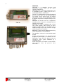
FUNCTION
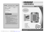
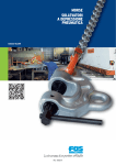
FKP-R/R2 is a complete pressure and
temperature control center for fan driven
electronic motor drives.
FKP-R/R2 keeps a constant controlled pressure
in ventilation systems. Typical area of use is
ventilating bathrooms and kitchens.
The drive is equipped with an internally mounted
pressure sensor, but it can also be connected to
an external sensor. Several types of external
temperature sensors can be connected in order
to perform temperature compensated pressure
control.
FKP-R/R2 can also be used as a temperature
controller and as a hysteresis controller from an
external sensor signal.
FKP-R/R2 can also be equipped with a Real
Time Clock (option), which makes the drive
capable of various forms of scheduling. These
include lowering the pressure reference at night
and weekly pressure schedules.
Monitoring is done with the onboard alarm relay
and analog output; and via MODBUS.
FKP-R2
The controller's enclosure is water-and dustproof
to IP54.
Settings and parameters can be viewed and
changed in plain English (or Swedish) on the
FKP-R/R2's large, four line, display using an
easy-to-use menu system controlled by a
navigation wheel.
Cable connections are made on screw terminals
and pressure hose on press-on hose
connectors.
FKP-R
FRABIL
FRACON
GRUPPEN
Frabil El AB
Bjurögatan 38
211 24 Malmö
Phone: +46 40-28 70 90
Fax: +46 40-18 47 09
www.frabil.se
USAGE INSTRUCTIONS
When the drive is powered, its status is shown
on the display. If the start signal is not
connected, "Drive Stopped" is shown. Upon
connection of the start signal to terminal 4 or 6,
the drive will start, and the status screen will be
shown.
Press the wheel to activate the display backlight,
and turn it to enter the menu system.
There is one top-level menu and several submenus. The basic menu system has two submenus: "Press/Temp. settings" and "System
settings". Navigate between the menus by
turning the wheel, and choose a menu by
pressing it. To exit a menu level, select "Back".
In the sub-menus, there are settings
(parameters) that can be changed. To change a
parameter, press the wheel when it is selected.
This will show the text "Choose" or "Change"
together with the value to be changed. Turn the
wheel to change the value, and press it to
confirm the change and return to the sub-menu.
Some menu items are only informational and
cannot be changed. Press the wheel to exit
these menus.
If a fault occurs, an error screen will be shown,
explaining the nature of the fault. Press the
wheel to reset it. For further details on error
handling, see the chapter Faults and Alarms.
Appendix A and B contain a quick reference to
all the settings in the FKP-R/R2 and its options.
FRABIL
FRACON
GRUPPEN
3
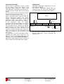
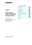
CONNECTION
FKP-R/R2 is powered by 230VAC but can also
be powered by 24VDC.
The card is galvanically isolated from the
incoming phase. All signal and control cables
are connected to screw clamps on this board.
display
From smoke
detector
N L
21 24 22
Incoming Alarm
230VAC
Frabil El AB
Bjurögatan 38
211 24 Malmö
M+ M- CMPW
1 2 3 4 5 6 7 8 9 10 11 12 13
A B 0 24
On/Off
NTC
temperature sensor
Figure 1. Connection for pressure control with
fixed out signal activated by smoke detector.
Outside temperature sensor connected on
terminal 9, 10.
Phone: +46 40-28 70 90
Fax: +46 40-18 47 09
www.frabil.se
4
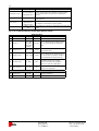
Table 1 shows terminal number and function.
Terminal Nr
Function
N
Supply phase och common
230VAC
L
21
Alarm Common
24
Alarm (OK)
22
Alarm (Fault)
A/M+
MODBUS+ (A eller D0)
B/MMODBUS- (B eller D1)
0/CM
MODBUS Common
PW24
Power supply for external units
1
10V Reference
0-10V IN 1 (external active
2
temperature sensor)
3
Signal common
4
24V Digital In 1 (start)
5
24V Output
6
24V Digital In 2 (start/fixed outsig.)
0-10V IN 2 (external pressure
7
sensor / hysteresis signal)
8
Signal common
9
Extern passiv NTC/PT1000
tvåtrådars temperatursensor
10
11
0-10V, 4-20mA or 0-20mA OUT
12
Signal common
13
24V Digital In 3 (extra)
Table 1. FKP-R/R2 signal connection.
Terminals 21 to 24 are connected to the alarm
relay. They are fully isolated from all other
voltages within the drive, and are capable of
switching 8A at 250VAC. Terminal 24 is closed
when the drive is free of faults.
Terminals M+, M- and 0 are the MODBUS
terminals. M- corresponds to MODBUS D1 or B,
while M+ is D0 or A. 0 is the MODBUS common
ground potential.
A 10V reference voltage is available on terminal
1. Terminal 2 is the 0-10V to connect an external
active temperature sensor when the drive is in
Temperature control mode or Temperature
compensating mode.
Signal common is available on terminals 3,8, 12
and 0/CM.
Terminals 4 and 6 are 24V digital inputs.
Connecting 24V to terminal 4 or 6 makes the
controller start, these signals are OR:ed
connected, connecting 24V to both signals will
stop the controller. Terminal 6 can also be used
as fixed out signal or fixed pressure. This
depends on the setting of ”System settings/Use
fixed ref.” parameter 62. In this case the OR
functions is disabled.
A 24V output is available on terminal 5.
Terminal 7 is a 0-10V analog input which can be
used to connect an external pressure sensor or
some other active sensor. This sensor should
have a 0-10V output; if it has 4-20mA output
then a (499ohm) resistor must be connected
FRABIL
FRACON
GRUPPEN
Frabil El AB
Bjurögatan 38
211 24 Malmö
between signal and common. Choose this with
parameter 75.
Terminal 9 and 10 is used to connect an external
passive NTC thermistor or a PT1000 sensor.
Terminal 11 is a 4-20mA or 0-20mA output,
which may be loaded with 0-560 ohms. Connect
a (499ohm) resistor and set “current out range”
to “0-20mA”, to get 0-10V output.
The function of the output current range is
chosen with parameter 63, found under "System
settings".
CONNECTION OF PRESSURE HOSE
If FKP-R/R2 is used as a pressure controller
then hoses to measure pressure must be
connected to the ventilation channel.
The internal pressure sensor has two 5mm hose
connections for positive and negative pressure.
Positive pressure (upper connection) is marked
with (+).
If the fan is an exhaust fan then the measuring
hose is connected to the negative connection
and the opposite side of the hose is connected
inside the ventilation channel.
For best measuring result the hose should be
connected so that the hose opening is in the
center of the channel and perpendicular to the
flow. The controller controls the pressure where
the hose is connected. For best result do not
connect the hose in direct proximity of the fan,
but some distance in to the channel.
The channel pressure is normally controlled
relative to the atmospheric pressure. If FKPR/R2 is mounted inside a fan or compartment
where the surrounding pressure can be other
than the atmospheric pressure, a second hose
should be connected to the positive connection
and the other side to a place with atmospheric
pressure.
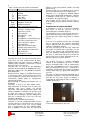
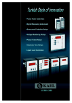
If the hose is subject to weather and wind then it
should be mounted in such manner that water
and dirt can not enter. Figure 2 displays a
suggestion of connecting the hose so that water
and dirt do not enter.
Figure 2. Mounting of pressure hose for
measuring of atmospheric pressure.
Phone: +46 40-28 70 90
Fax: +46 40-18 47 09
www.frabil.se
The hose end should also be placed in such way
it is not affected by wind as this changes the
pressure.
NOTE. If water or dirt enters the internal
pressure sensor it can damage the sensor.
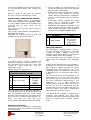
CONNECTION OF TEMPERATURE SENSOR
There are multiple choices in temperature
sensor to the FKP-R/R2. NTC 100Kohm (4FKPT1), NTC 10Kohm (4FKP-T2) or PT1000 can be
used but also an active sensor can be
connected.
This active sensor can have either current or
voltage output.
If no sensor is connected then ”NO SENSOR” is
displayed in the display.
FKP-R/R2 has separate inputs for NTC and
PT1000 sensors on terminal 9 and 10.
5
• Pressure control. The FKP-R/R2 will use an
external or internal pressure sensor to control
pressure with its output signal.
• Temperature compensated pressure control.
This has the same function as pressure
control, with the exception that a temperature
sensor is used to compensate the reference
pressure.
• Temperature control. Controls the output
signal using a temperature signal. No
pressure sensor is used in this mode.
• MODBUS 0-10V controls the controller as if it
had an analog signal to control the output
signal directly. This option is only available if
the drive has the added MODBUS option.
CONTROLLER SETTING:
Nr:
Parameter:
2
Figure 3. Temperature sensor 4FKP-T2.
If an active sensor is used it is connected to
terminal 2. Settings 21 ”Active temp min.” sets
the temperature at 0V from the sensor and
settings 22 ”Active temp max.” sets the
temperature at 10V.
Settings 20 sets the sensor in use.
PRESS/TEMP. SETTINGS:
(Temperature controller settings)
Nr:
Parameter:
Value:
NTC 100k,
NTC 10k,
20 Temp. sensor type
PT1000,
Active,
MODBUS
21 Active temp. min
-50 - 0°C
22 Active temp. max
0 - 100°C
The temperature sensor should be mounted in
such way that it does not get heated by hot air
from the ventilation shaft. The sensor should
therefore not be placed in the fan exhaust or on
the fan itself as it could be warm from the air.
Direct sun light can also give false
measurements and should therefore be avoided.
CONTROLLER SETTING
The way the drive is controlled is selected with
parameter 2. There are four ways the FKP-R/R2
can be controlled:
FRABIL
Frabil El AB
FRACON
Bjurögatan 38
GRUPPEN
211 24 Malmö
Control method
Value:
Pressurecont.,
Pressurecont./
Tempcomp.,
Temp control,
MODBUS 0-10V
PRESSURE CONTROL
The FKP-R/R2 is equipped with a built in
pressure controller, and a pressure sensor with
a range of -1000 - 1000Pa. To use this
controller, select "Pressurecont." in parameter 2
"Control method" under “Drive settings”.
It is also possible to use an external pressure
sensor with the FKP-R/R2. See connection
table.
Setting up the FKP-R/R2 pressure controller is
simple and fast. The pressure controller is of PItype. Its gain is set with parameter 15, and its
integration time with parameter 16. If an
integration function is not desired, set the time to
0. Normally there is no need to change these
settings.
The reference pressure of the controller is set
with parameter 10. In this menu the actual
compensated pressure reference value after it
has been temperature compensated is also
displayed. I.e. if it is warm outside the
compensated pressure ref will be the same as
pressure ref, but if it is cold outside then the
compensated pressure ref will be lower the set
pressure reference. This value is displayed to
help setting correct reference value.
The output of the controller is limited by the
maximum and minimum out signal limits
(parameters 40 and 41). Note that parameter 40
and 41 are located in the "System settings"
menu.
Phone: +46 40-28 70 90
Fax: +46 40-18 47 09
www.frabil.se
6
Parameter 10 is used to select the type of
pressure sensor in use, internal or external.
The pressure sensor (internal or external) can
be calibrated by setting the zero pressure point.
This is done by selecting "Yes" on parameter 14
when there is no difference in pressure applied
to the pressure inputs. The FKP-R/R2 will use
the measured pressure as the new zero
pressure point. The internal sensor is calibrated
from the factory and usually does not require
further calibration.
If an external sensor is to be used, the pressure
corresponding to 0V should be set in parameter
12, and the pressure corresponding to 10V in
parameter 13. This should always be followed by
a zeroing of the pressure as described above.
A forced fixed pressure can be set by an
external input signal, see ”System settings”.
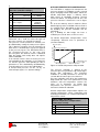
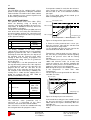
OUTSIDE TEMPERATURE COMPENSATION
The FKP-R/R2 is equipped to compensate for
pressure changes in ventilation systems caused
by the changing outside temperature. When the
outside temperature drops, a chimney effect
often occurs in ventilation channels, causing
increased airflow. To compensate for this, the
pressure reference is lowered as seen in figure
4.
At -15°C the chimney effect is around 1,7Pa/m
build height up to the ventilation exhaust. At 0°C
it is around 1Pa/m. Depending on the height of
the building, the pressure reduction can be
calculated.
E.g. a building of 10m height can have a
reduction pressure of 10x1,7=17Pa at -15°C.
To activate temperature compensation, select
"Tempcomp. Pressure cont." in parameter 2
("Control method").
Pressure (Pa)
Pressure reduction
PRESS/TEMP. SETTINGS:
(Pressure controller settings)
Nr:
Parameter:
Value:
Pressure ref (external)
0 - 1500Pa
10
(internal)
0 - 1000Pa
54 Fixed pressure
0 - 1000Pa
internal,
external,
11 Press. input
MODBUS
12 Ext. min press.
-1500 - 0Pa
13 Ext. max press.
0 - 1500Pa
14 Zero pressure
Yes, No
15 Controller gain Kp
0 - 999
16 Integ. time Ti
1 - 999
Pressure reference
Temperature (°C)
Min Temperature
Max Temperature
Figure 4. Outside temperature compensation.
The pressure reduction is applied to the
reference pressure (parameter 10), and changes
linearly with temperature. The maximum
reduction is set with parameter 17 and can be
set from 0Pa to current pressure reference.
Pressure reduction starts when the temperature
drops below the value set in parameter 18, and
continues until the temperature reaches the
value set in parameter 19. Below that
temperature, the pressure reference is held
constant at maximum reduction.
Outside temperature compensation requires an
external temperature sensor. Connection and
mounting instructions see section Connection of
temperature sensor.
PRESS/TEMP. SETTINGS:
(Outside temperature compensation /
Temperature control)
Nr:
Parameter:
Value:
17 Press. reduction
0 – press.ref. Pa
18 Temperature max
-50 - 50°C
19 Temperature min
-50 - 50°C
FRABIL
FRACON
GRUPPEN
Frabil El AB
Bjurögatan 38
211 24 Malmö
Phone: +46 40-28 70 90
Fax: +46 40-18 47 09
www.frabil.se
7
PRESSURE CONTROLLER ALARMS
The FKP-R/R2 will always indicate a pressure
alarm via the alarm relay. If parameter 23, ”Stop
on alarm”, is selected (set to 'yes'), the drive will
also stop on these alarms. Otherwise the drive
will continue to run the motor during these
alarms. Alarm limits for under- and over
pressure are set with parameters 24 and 25
respectively.
PRESS/TEMP. SETTINGS:
(Pressure controller alarms)
Nr:
Parameter:
Value:
23 Stop on alarm
Yes/No
24 Alarm upper lim.
-1500 - 1500Pa
25 Alarm lower lim.
-1500 - 1500Pa
26 Alarm delay
0 - 1000sec
To prevent the pressure alarms from tripping
during short pressure pulses (caused by wind
etc), the alarms are delayed. In order to cause
an alarm, the pressure must be outside the limits
for longer than the time set in parameter 26.
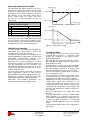
Out signal (%)
Max out signal
Min out signal
Temperature (°C)
Min Temperature
Max Temperature
Out signal (%)
Max out signal
Min out signal
Temperature (°C)
Max Temperature
Min Temperature
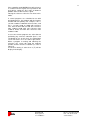
Figure 5. Temperature control.
TEMPERATURE CONTROL
It is also possible to control the FKP-R/R2 by
temperature only. This mode is chosen by
selecting "Temp. contr" in parameter 2.
Temperature control works by changing the out
signal proportional to temperature, just like how
temperature
compensation
changes
the
pressure reference. This is shown in figure 5.
Parameter 34 sets the temperature at which
maximum out signal is used and parameter 33
sets the temperature for the minimum. The
maximum and minimum out signal are set in the
usual manner with parameters 40 and 41 in the
"System settings" menu.
The temperature signal can be from an external
active temperature sensor or from passive
NTC/PT1000 sensor connected to terminal 9,10.
Inverting the function is done by setting ”Min
temperature” higher than ”Max temperature”.
Connection and mounting instructions see
section Connection of temperature sensor.
FRABIL
FRACON
GRUPPEN
Frabil El AB
Bjurögatan 38
211 24 Malmö
SYSTEM SETTINGS
The language used in the menu system can be
changed with parameter 1, "Language". Two
choices are available in the current version,
English and Swedish.
Max and Min out, parameter 40 and 41, limits
the controller out signal so that the signal never
go beyond these limits.
A fixed reference can be chosen with parameter
62 which will be activated by terminal 6. NOTE,
this will configure terminal 6 to trigger fixed
reference and will not be trigger for start signal.
To use fixed reference signal, choose ”Use fixed
ref.” or ”Hysteresis cont.”.
The fixed signal can either be a fixed out signal
or fixed pressure ref. The fixed pressure is set
by parameter 54 under ”Press/Temp. settings”.
FKP-R/R2 has built in hysteresis control of an
analog input signal. Use parameter 71 to
activate this function. The choices are the same
as for parameter 62. Both functions can be used
simultaneously and do always have priority over
pressure and temperature control and also the
timer function.
Fixed out signal always has priority over fixed
pressure.
E.g. if the FKP-R/R2 is in pressure control mode
when terminal 6 is activated, then pressure
control will be disabled and the controller will set
a fixed out signal. If terminal 6 is deactivated
then the controller will return to pressure control
mode.
At fixed or forced out signal an (F) is displayed in
the display.
Phone: +46 40-28 70 90
Fax: +46 40-18 47 09
www.frabil.se
8
Start and stop levels for the hysteresis control
are set by parameter 72 and 73. A stop delay
can be accomplished by setting parameter 74.
Inverting the function is done by setting stop
level higher then the start level.
Terminal 7 is the analog in signal for the
hysteresis control and parameter 75 set the
input range. If the in signal is a 4-20mA signal
then a 499ohm resistor must be connected
between terminal 7 and common.
SYSTEM SETTINGS:
Nr:
Parameter:
61 Language
40 Max out
41 Min out
44 Fixed outsignal
62 Use fixed freq.
71 Hysteresis control
72 Hysteresis start
73 Hysteresis stop
74 Hysteresis stop-delay
75 Insignal on term 7
63 Current out
65 System log
66 System error log
67
68
69
70
Drive information
Reset logs
Restore default settings
System states
Value:
Swedish,
English
0 – 100%
0 – 100%
0 – 100%
Never,
Freq. on
terminal 6,
Pressure on
terminal 6
off,
start fixed freq.,
start fixed
pressure
1 – 100%
0 – 99%
0 – 15min
0-10V,
4-20mA
(499Ohm)
4-20mA,
0-20mA
Days and Hours
See error
screen
Model, firmware
Yes, No
Yes, No
System data
The entire controller can be restored to default
settings by changing parameter 69. Language
and MODBUS parameters will also be reset.
”Reset logs” clear all error logs.
”System states” shows a good overview of many
of the systems internal variables. Here can all
input and outputs of the controller be viewed.
This list is primarily used for troubleshooting.
”System log” displays the runtime of the
controller and can not be reset.
The FKP-R/R2 model and firmware version can
be found in ”Drive information”.
FRABIL
FRACON
GRUPPEN
Frabil El AB
Bjurögatan 38
211 24 Malmö
MODBUS/RTU
With the RS485 MODBUS option, the FKP-R/R2
can communicate with a MODBUS master using
MODBUS/RTU. Essentially all the settings that
can be changed via the menu system can also
be changed via MODBUS and more important
data can be read out. See the MODBUS Data
Dictionary for more information (page 15).
MODBUS SETTINGS:
Nr:
Parameter:
100 MODBUS address
101 MODBUS parity
102 MODBUS baudrate
Value:
1 - 247
None, Even,
Odd
2400, 4800,
9600, 19200
MODBUS parameters are available under
"System settings/MODBUS settings", and
consist of address, parity and baudrate (bitrate).
FAULTS AND ALARMS
If a fault occurs, it is always shown on an error
screen.
The controller will stop and restart automatically
60 seconds after any fault ceases. The
countdown to restart is shown on the screen.
If the fault persists, the controller will go into
alarm mode after 60 seconds. This will be
indicated by the text "Drive alarm!", and by the
alarm relay changing to the fault state. Once the
controller is in alarm mode, it can only be
brought out of it by pressing the encoder wheel,
or by interrupting the power supply.
• “EEPROM error” is displayed if the parameter
memory is corrupt. The memory is reset to
default controller settings. Please contact
service.
• In pressure controlled mode, the controller
will also be subject to "Over pressure" and
"Under pressure" faults. These occur when
the pressure is too high or too low compared
to the settings (24 and 25) of the pressure
controller. These faults can be set to not stop
the controller even if the alarm relay is
triggered. This is controlled by the "Stop on
alarm".
To aid in troubleshooting, the FKP-R/R2 will
record all faults for later viewing. This recording
will not be reset by loss of power to the drive.
The faults are shown in the "System
settings/System error log" parameter. The first
items shown are the total count of errors of each
type that have occurred. Below the separating
line, the last 8 faults are shown. The most recent
fault is shown at the top. Each fault has a
number to shown how many faults have
occurred in total. (For example, the third fault to
have occurred is numbered 3.)
It is possible to reset the error history of the
controller using the "System settings/Reset logs"
Phone: +46 40-28 70 90
Fax: +46 40-18 47 09
www.frabil.se
9
parameter. This will have no other effect on the
controller.
CONTROLLER STOPPED
If a start signal is not connected to either
terminal 4 (forward) or 6 (reverse), the display
will show the “controller stopped screen”. The
menus can as always be accessed by turning
the encoder wheel.
The information screen will appear as soon as a
start signal is connected.
INFORMATION SCREEN
The FKP-R/R2 shows many types of information
while running, to aid in diagnostics and
troubleshooting.
When the controller is active (a start signal is
connected, and no faults have occurred), the
display will show relevant status information.
Output signal will always be shown. If pressure
control is selected, the screen will also show the
current pressure. If temperature compensation
or temperature control is selected, the current
outside temperature will also be shown. If the
controller has the timer option, this will be
display at the bottom of the display.
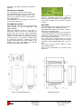
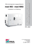
Figure 7. FKP-R2 dimensions.
FRABIL
FRACON
GRUPPEN
Figure 6. FKP-R/R2 Information screen in
pressure controlled mode with temperature
compensation. The built-in timer, program P1, is
active and is forcing (F) the pressure reference
to 100%.
MOUNTING
The FKP-R/R2 is water and dust protected up to
IP54 classification. It is quickly and easily
mounted thanks to holes in the corners. Lift the
lid to access mounting holes.
To maintain water protection, the seal on the lid
must be undamaged, and the screws tightened.
NOTE! Do not over tighten the screw as this can
cause damage to the threads.
The cable glands should always be proper
fastened and all cable glands that are not used
should be replaced with blind plugs to ensure
IP54.
The reverse side of the lid contains a quick
connection reference.
The pressure connections are sized for 5mm
PVC hose.
FKP-R dimensions.
Frabil El AB
Bjurögatan 38
211 24 Malmö
Phone: +46 40-28 70 90
Fax: +46 40-18 47 09
www.frabil.se
10
OPTIONS
The FKP-R/R2 can be equipped with a timer
option in order to provide a complete ventilation
control solution. The built-in timer allows control
of the controller pressure and out signal based
on time-of-day and weekday.
BUILT-IN TIMER SETTINGS
The optional built-in Real Time Clock (RTC)
allows for lowering, rising or forcing the
reference value of the controller (be it pressure,
temperature or MODBUS reference) based on
almost arbitrary schedules.
The RTC has a backup battery to allow it to keep
track of the time even when the FKP-R/R2 has
no external power applied. The current time and
day is set with parameter 86 and 87 respectively
under "System settings".
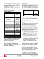
If temperature control is used, then the reference
value change the ”Max out” between 0-400%,
but max 10V as this is the controller maximum
out signal.
The set out signal ramp will be moved up or
down according to figure 8.
Out signal (0-10V)
100% max
Max out signal
Min out signal
Temperature (°C)
Min Temperature
86
System clock
87
System clock
Value:
Monday Sunday
hh:mm:ss
The weekly schedule is set under "Timer
settings" by first choosing one of seven available
programs (parameter 80). This is followed by
choosing the start and stop times, the day to run
the program, and the reference value while
running it. From the factory, all programs are
deactivated by setting "Run Px on" (parameter
81) to "No days".
The starting time is set with parameter 82, and
the stop time with parameter 83. If the stop time
is set before or the same as the start time, the
program will run from the start time on the
chosen day, to the stop time on the next day.
For example, if the chosen day is Monday, the
starting time is 14:00, and the stopping time is
07:00, the program will run from 14:00 on
Monday until 07:00 on Tuesday.
TIMER SETTINGS:
Nr:
Parameter:
80 Chosen program
81
Run Px on
82
83
84
85
Start time for Px
Stop time for Px
Ref.value of Px
Force ref. value
FRACON
GRUPPEN
If ”Force ref. value” parameter 85 is set to ”yes”
then the reference value will be constant and
independent of the temperature.
I.e. the controller will force the out signal to be
constant between 0-400% of ”Max out”.
Temperature compensated pressure works in
the same way as temperature control regarding
offset of the pressure curve and the forcing
function.
If the controller have a pressure reference set to
100Pa and reference value set to 70% and
”force ref. value” to ”yes”, then the controller will
lower the actual pressure ref to 70Pa when the
program is active even if it is cold outside.
With forcing off the pressure will drop even lower
if the temperature is lower then ”Max
Temperature”.
The out signal can not go outside the ”Max out”
and ”Min out” limits.
Pressure (Pa)
Pressure ref 120%
Value:
P1 - P7
No days,
Mon - Sun,
Weekdays,
Weekends,
All days
00:00 - 23:59
00:00 - 23:59
0 - 400%
Yes, No
The reference value (parameter 84) is
expressed as a percentage of the active
reference value of the drive from 0 to 400%.
If 0% reference is set then the controller will stop
the out signal when this program is active.
FRABIL
Figure 8. Change of out signal reference.
Frabil El AB
Bjurögatan 38
211 24 Malmö
Pressure reduction
SYSTEM CLOCK:
Nr:
Parameter:
Max Temperature
Pressure ref 100%
Pressure ref 80%
Temperature (°C)
Min Temperature
Max Temperature
Figure 9. Change in pressure reference.
In the mode where only pressure control is used,
the pressure reference is changed between 0400% and the out signal is limited by ”Max out”
and ”Min out”.
Forcing the reference value has no effect in this
mode.
Phone: +46 40-28 70 90
Fax: +46 40-18 47 09
www.frabil.se
11
If the controller mode MODBUS 0-10V reference
is used then the out signal can vary between 0V
and 10V by setting the “Ref. value” to between
0-400% of the 0-10V reference signal.
Forcing the reference value has no effect in this
mode.
If several programs are scheduled to run with
overlapping times, the program with the highest
number will take priority. For example, if P1 is
set from 12:00 to 17:00 with reference 30%, and
P2 is set from 15:00 to 16:00 with reference
10%, then the drive will run with 30% reference
from 12:00 to 15:00, with 10% reference from
15:00 to 16:00, and with 30% reference from
16:00 to 17:00.
In case one or more programs are active but not
performing any reference reduction (that is, not
scheduled to run at this time), the information
screen will show "P*" in the lower right corner.
When a program is running and reducing the
reference, the screen will show the program
number and the reference reduction (as seen in
Figure 6).
If reference forcing is active then a (F) will be
display in the display.
FRABIL
FRACON
GRUPPEN
Frabil El AB
Bjurögatan 38
211 24 Malmö
Phone: +46 40-28 70 90
Fax: +46 40-18 47 09
www.frabil.se
12
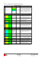
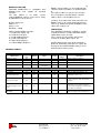
Appendix A. Quick reference to FKP-R/R2 menu system.
CONTROLLER SETTING:
Nr:
Parameter:
Value:
Description:
Default:
Pressure cont.,
Press. cont./
Tempcomp.
2 Control method
Choose the way the controller is controlled.
Choices are 0 - 10 V frequency reference;
Press. Cont./ Pressure control with or without temperature
Temp cont.
Tempcomp. compensation; Temperature control only.
MODBUS 0-10V
MODBUS 0-10V is used when the controller
is controlled from a MODBUS ref. signal.
PRESSURE/TEMPERATURE SETTINGS:
Nr:
Description:
Value:
Default:
0 - 1500Pa
0 - 1000Pa
100Pa
17 Pressure reduction
0 - pressure
ref.(Pa)
15Pa
54 Fixed pressure
0 - 1000Pa
100Pa
18 Temperature max
-50 - 50°C
15°C
Upper corner point for temp. comp.
19 Temperature min
-50 - 50°C
-15°C
Lower corner point for temp. comp.
Parameter:
Pressure ref (external)
(internal)
10
23 Stop on alarm
Pressure reference of the controller, also
shows actual value and pressure reference
value after temperature compensation.
Magnitude of the decrease of the pressure
reference at the lower temperature
compensation corner point.
Sets fixed frequency ref if this setting is used
from parameter 62 or 71.
"Yes" will stop the out signal of the controller
(and activate the alarm relay) on pressure
alarms, "No" will only activate the alarm
relay.
Yes, No
Yes
24 Alarm upper limit
-1500-1500Pa
400Pa
25 Alarm lower limit
-1500-1500Pa
25Pa
0 - 1000sec
600sec
NTC 100k,
NTC 10k,
PT1000, active,
MODBUS
NTC 10k
21 Active temp min.
-50 - 0°C
-40°C
Temperature with 0V from active sensor.
22 Active temp max.
0 - 100°C
80°C
Temperature with 10V from active sensor.
11 Pressure input
internal,
external,
MODBUS
internal
Pressure sensor type, Choose MODBUS if
pressure ref is controlled from MODBUS.
12 External min pressure
-1500 - 0Pa
0Pa
13 External max pressure
26 Alarm delay
20 Temp. sensor type
Alarm limit for overpressure.
Alarm limit for underpressure.
Time until a pressure alarm is generated.
Type of temperature sensor (active sensors
are connected to terminal 2 or from
MODBUS).
Pressure with 0V from external sensor.
0 - 1500Pa
999Pa
14 Zero pressure
Yes, No
-
Calibrate actual pressure to zero now.
Pressure with 10V from external sensor.
15 Controller gain Kp
0 - 999
0
Gain applied to the difference between the
actual and reference pressures.
16 Integ. time Ti
1 - 999
400
Controller integration time.
The colors mark which parameters are active dependant on the choice of
Control method
FRABIL
FRACON
GRUPPEN
Frabil El AB
Bjurögatan 38
211 24 Malmö
Phone: +46 40-28 70 90
Fax: +46 40-18 47 09
www.frabil.se
13
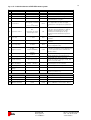
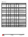
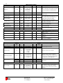
Appendix A. Quick reference to FKP-R/R2 menu system.
S YSTE M SE TTI NG S:
N r:
Pa ram eter:
61 L an gu age
V al ue :
Sw ed ish, En glish
De fa ult:
S we dish
40 M ax o ut
5 0 - 1 00 %
1 00 %
U pp er limit fo r cont ro lle r ou t sig na l.
41 M in o ut
0 - 5 0%
0%
Lo w er limit for co nt ro lle r ou t sig nal.
0 - 1 00%
5 0%
Fixed ou t sig nal, use d sett in gs 62 is ac tive
an d term ina l 6 h as a sig na l.
n eve r,
Ou t s ig na l on te rm ina l
6,
pre ss. o n term inal 6
N ever
Fixed ou t sig nal, use d wh en te rm ina l 6 and 4
ha s a sign al. Ch oo se fixe d ou t sign al,
pa ram et er 44 o r f ixe d pressu re , p aram e ter
54 .
Off ,
s tart fixe d ou t sign al,
st art f ixe d p re ssu re
Of f
C ho ose w hat to ac tivate w he n t he hyst eresis
co ntrol h as be en act iva te d b y a signa l on
te rm ina l 7. Fixed freq uen cy is s et by
pa ram et er 44 a nd fixed press ure b y
pa ram et er 54 . O ff d ea ctivat es hyste re sis
co ntrol.
72 H yst. sta rt
1 - 1 00%
4 5%
C ho ose hyst eresis s tart le vel o n a na log
te rm ina l 7.
73 H yst. sto p
0 - 9 9%
3 5%
C ho ose hyst eresis s top leve l on an alo g
te rm ina l 7.
74 H yst. St op de lay
0- 1 5m in
0m in
Se ts off de la y. A t h yste re sis sto p the ac ual
sto p is de la yed th is tim e.
75 I nsign al o n term 7
0-10 V,
4 -2 0m A (4 99 Ohm )
0-10 V
Se t s ig na l scaling o n t erm ia l 7. If 4-20 m A is
us ed the n an exte rn al re sist or (49 9o hm ) is to
be co nn ecte d bet we en th e t erm inal and
Sig na l Co m m on.
63 C u rren t o ut ra ng e
4 -2 0m A,
0 -20m A
0 -2 0m A
65 S ystem lo g
D a ys an d hou rs
-
Sh ow s t he tim e t he con troller h as b ee n
run ning w it h s tart s ig na l con ne cted .
66 S ystem erro r log
See e rror scre en
-
Sh ow s t he cou nt of ea ch t ype of fa ult, an d
th e 8 m os t rece nt fa ults.
67 D rive I nfo rm a tion
Mo del,
-
The typ e, m an ufa ctu re r, firmw a re revision
da te an d opt ions of th e co nt ro lle r.
Y es, No
-
R ese ts t he syste m error log .
Y es, No
-
R est ores a ll pa ra m ete rs to de fau lt.
Syst em d at a
-
Sh ow n m any of the int erna l variable s o f th e
syste m (for se rvice u se).
44 Fixed o utsig nal
62 U se fixed ref.
71 H yste resis co ntro l
68 R e set lo gs
69
R e store de fau lt
se ttin gs
70 S ystem stat es
firm w are
D es cription:
M en u syst em lan gu ag e.
C ho ose curren t o ut signa l ran ge.
M OD BU S SE TTI NG S: (under S ystem Se ttings )
Pa ram eter:
V al ue :
De fa ult:
D es cription:
1 00 M OD BU S ad dress
1 - 24 7
1
C ho ose M OD BU S-ad dress of this con tro ller.
1 01 M OD BU S pa rity
No ne , E ven , Od d
E ven
C ho ose M OD BU S p arity.
1 02 M OD BU S ba ud ra te
2 400 , 4 80 0, 96 00 ,
1 92 00
1 92 00
C ho ose M OD BU S c om m un ica tion b it ra te.
N r:
FRABIL
FRACON
GRUPPEN
Frabil El AB
Bjurögatan 38
211 24 Malmö
Phone: +46 40-28 70 90
Fax: +46 40-18 47 09
www.frabil.se
14
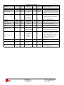
STATUS SCREENS:
Parameter:
Information screen
Value:
Description:
Pressure/temp/ref,
Out signal, timer
Always shown in when the controller is running. Shows
"P*" or "xx% Px" if the controller has an active timer
function.
Code screen
Menu code
Gives access to the parameters of the controller, see the
inside of the lid.
Error screen
EEPROM error,
Over pressure,
Under pressure
Shows controller faults and alarms. Alarms are reset by
pressing the encoder wheel or power cycling.
Stopped screen
Controller stopped
text
Shown when the controller is stopped due to missing start
signal.
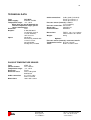
Appendix B. Quick reference to FKP-R/R2 options menus.
TIMER SETTINGS:
Parameter:
Nr:
80 Chosen program
Value:
P1 - P7
Default.:
P1
Description:
Choose a program to change
81 Run Px on
No days,
Mon. - Sun.,
Weekdays,
Weekends,
All days
No days
82 Start time for Px
00:00 - 23:59
00:00
Choose which time on the chosen day
the program starts.
83 Stop time for Px
00:00 - 23:59
00:00
Choose which time the program stops. If
the chosen time is before the start time,
the program will run until the next day.
84 Ref value for Px
0 - 400%
100%
Percentage of pressure or output
reference used when the program is
active. 0% stops the output signal.
85 Force reference
Yes, No
No
86 System clock
87 System clock
FRABIL
FRACON
GRUPPEN
Choose which days the program should
run on. Select "No days" to deactivate
timer.
Forces the reference value so it do not
change over temperature.
CLOCK SETTINGS: (under System Settings)
MondaySets the current day
Sunday
hh:mm:ss
Sets the current time of day
Frabil El AB
Bjurögatan 38
211 24 Malmö
Phone: +46 40-28 70 90
Fax: +46 40-18 47 09
www.frabil.se
15
Modbus register addresses are numbered from
1 but the actual sent address is numbered from
0.
The register addresses that are referenced in
this user guide are numbered from 1 and the
address that is sent should be one less.
MODBUS-FUNCTION
FKP-R/R2 Modbus/RTU is compatible with
SCADA-system and support all standard
functions.
The units address is set under ”system
settings/MODBUS settings” in the menus, parity
and baudrate are also set here.
”Scaling:” in the table marks how many times the
Modbus-value is up scaled compared to actual
value. E.g. 10Volt corresponds to Modbus-value
100 as the scaling is 10.
Default settings are:
Address = 1
Parity = even
Baudrate = 19200
LIMITATIONS
Only ”MODBUS CONTROL SIGNALS” shall be
used when FKP-R is remote controlled and the
update Write-cycles are high.
These signals are not saved in the internal
memory as all other Write-signals are.
FKP-R support Modbus-functions:
1 = Read Coils (Logisk 1/0)
2 = Read Discrete Input
3 = Read Holding Register
4 = Read Input Register
6 = Write Single Register
16 = Write Multiple Registers
All other Write-signals may not be continuous
written to. Continuous write to these signals will
destroy the internal EEPROM memory as it has
limited number of write-cycles.
MODBUS-SIGNALS
I/O-SIGNALS
Digital in 1 (Start)
Function
type:
1, 2
1
-
-
-
Indicates signal on teminal 4
Digital in 2 (Start)
1, 2
2
-
-
-
Indicates signal on teminal 6
Digital in 3
1, 2
3
-
Indicates the alarm relay state, terminal 2124.
Signal name:
Address:
Value:
Scaling:
Default
settings:
Description:
Indicates signal on teminal 13
1=on (Normal run),
0=off (Error)
Alarm relay
1, 2
4
-
0 - 10V IN 1
3, 4
51
-
10
-
Shows in signal on Terminal 2. (V)
0 - 10V IN 2
3, 4
52
-
10
-
Out side temperature
3, 4
53
-
100
-
Shows in signal on Terminal 7. (V)
Shows out side temperature from external
temperature sensor. (°C)
MEASURING SIGNALS
Pressure act. value
3, 4
54
-
1
-
Shows the pressure from the internal
pressure sensor or from external if it is
used.(Pa)
Compensated pressure ref.
value
3, 4
55
-
1
-
Actual pressure ref. value. Shows the
pressure after temperature compensation
and or timer ref. changes.
Out signal
3, 4
56
-
1
-
Shows out signal of the controller in %.
FRABIL
FRACON
GRUPPEN
Frabil El AB
Bjurögatan 38
211 24 Malmö
Phone: +46 40-28 70 90
Fax: +46 40-18 47 09
www.frabil.se
16
MODBUS-SIGNALS
Signal name:
Control method
Function
type:
3, 6, 16
Address:
82
CONTROL SETTINGS-SIGNALS
Default
Scaling:
Value:
settings:
1 = Pressure control
2 = Temp.comp.
Pressure cont.
3 = Temp. control
4 = MODBUS 0 - 10V
-
1
3, 6, 16
Pressure reduction
3, 6, 16
84
0 - pressure ref.
1
Max temperature
3, 6, 16
85
-50 - 50°C
100
Min temperature
3, 6, 16
86
-50 - 50°C
100
-1500
(-15°C)
Stop on alarm
3, 6, 16
87
0 = no
1 = yes
-
1
Alarm upper limit
3, 6, 16
88
-1500-1500Pa
1
Alarm lower limit
3, 6, 16
89
-1500-1500Pa
1
Alarm delay
3, 6, 16
90
0 -1000sec
1
-
1
-4000
(-40°C)
Temperature sensor type
3, 6, 16
91
0 = NTC 100k
1 = NTC 10k
2 = PT1000
3 = Active
4 = MODBUS
Aktive min temp.
3, 6, 16
92
-50 - 0°C
100
Aktive max temp.
3, 6, 16
93
0 - 100°C
100
Pressure input
3, 6, 16
94
0 = Internal
1 = External
2 = MODBUS
-
External min pressure
3, 6, 16
95
-1500 - 0Pa
1
External max pressure
3, 6, 16
96
0 -1500Pa
1
Zero pressure
3, 6,16
97
0 = no
1 = yes
-
Controller gain Kp
3, 6, 16
98
0 - 999
1
Integ. time Ti
3, 6, 16
99
1- 999
1
Fixed pressure
3, 6, 16
100
0 - 1000Pa
1
FRACON
GRUPPEN
Set control method.
PRESSURE/TEMPERATURE SETTINGS-SIGNALS
0 - 1500Pa
83
1
100 (100Pa) The controller pressure reference value. (Pa)
0 - 1000Pa
Pressure ref (external)
(Internal)
FRABIL
Description:
Frabil El AB
Bjurögatan 38
211 24 Malmö
15 (15Pa)
Magnitude of the decrease of the pressure
reference at the lower temperature
compensation corner point.
1500 (15°C) Upper corner point for temp. comp.
Lower corner point for temp. comp.
"Yes" will stop the controller (and activate
the alarm relay) on pressure alarms, "No"
will only activate the alarm relay.
400 (400Pa) Alarm limit for overpressure.
25 (25Pa)
Alarm limit for underpressure.
600 (600sec) Time until a pressure alarm is generated.
Type of temperature sensor (active sensors
are connected to terminal 2 or from
MODBUS).
Temperature with 0V from active sensor.
8000 (80°C) Temperature with 10V from active sensor.
0
0 (0Pa)
Pressure sensor type, Choose MODBUS if
pressure ref is controlled from MODBUS.
Pressure with 0V from external sensor.
999 (999Pa) Pressure with 10V from external sensor.
0
Calibrate actual pressure to zero now.
Gain applied to the difference between the
actual and reference pressures.
400
Controller integration time.
Sets fixed frequency ref if this setting is used
100 (100Pa)
from parameter 62 or 71.
0
Phone: +46 40-28 70 90
Fax: +46 40-18 47 09
www.frabil.se
17
Language
3, 6, 16
101
SYSTEM SETTINGS-SIGNALS
0 = Swedish
0
1 = English
50 - 100%
1
100 (100%)
Max out signal
3, 6, 16
102
Min out signal
3, 6, 16
103
0 - 50%
1
0 (0%)
Fixed outsignal
3, 6, 16
104
0 - 100%
1
50 (50%)
0 = Never
1 = Out signal on
terminal 6,
2=Pressure on
terminal 6
Use fixed ref. signal
3, 6, 16
105
Reset logs
3, 6, 16
106
Reset alarm
3, 6, 16
107
Current out range
3, 6, 16
108
Restore default
settings
3, 6, 16
109
0 = no, 1 = yes
110
0 = 0-10V,
1 = 4-20mA (499Ohm)
Insignal on term 7
3, 6, 16
0 = no, 1 = yes
0 = Not reset
1 = Reset
0 = 4-20mA,
1 = 0-20mA
Menu system language.
Upper limit for controller out signal.
Lower limit for controller out signal.
Fixed out signal, used when setting 62
(signal 105) is used and terminal 6 is high.
Fixed out signal, used when terminal 6 and 4
has a signal. Choose fixed ref signal,
parameter 44 (signal 104) or fixed pressure,
parameter 54 (signal 100).
-
0
-
0
-
0
-
0
Choose current out signal range.
-
-
Restores all parameters to default.
0
Set signal scaling on termial 7. If 4-20mA is
used then an external resistor (499ohm) is to
be connected between the terminal and
Signal Common.
-
0
Choose what to activate when the hysteresis
control has been activated by a signal on
terminal 7. Fixed frequency is set by
parameter 44 (signal 104) and fixed pressure
by parameter 54 (signal 100). Off
deactivates hysteresis control.
-
Resets the system error log.
Reset the controller if it has tripped from a
fault.
Hysteresis control
3, 6, 16
111
0 = Off,
1 = Start fixed out
signal,
2 = Start fixed
pressure
Hysteresis start
3, 6, 16
112
1 - 100%
1
45 (45%)
Choose hysteresis start level on analog
terminal 7.
Hysteresis stop
3, 6, 16
113
0-99%
1
35 (35%)
Choose hysteresis stop level on analog
terminal 7.
Hysteresis stop delay
3, 6, 16
114
0 - 15min
1
0 (0 min)
Sets off delay. At hysteresis stop the acual
stop is delayed this time.
FRABIL
FRACON
GRUPPEN
Frabil El AB
Bjurögatan 38
211 24 Malmö
Phone: +46 40-28 70 90
Fax: +46 40-18 47 09
www.frabil.se
18
TMER SETTINGS-SIGNALS
Chosen program
3, 6, 16
117
1 - 7 = P1 - P7
-
1
Choose a program to change.
-
0
Choose which days the program should run
on. Select "No days" to deactivate timer.
Rin Px on
3, 6, 16
118
0 = No days
1-7 = Mon. - Sun.
8 = Weekdays
9 = Weekends
10 = All days
Star time Hours
3, 6, 16
119
00:XX - 23:XX
1
0
Start time Minutes
3, 6, 16
120
XX:00 - XX:59
1
0
Stop time Hours
3, 6, 16
121
00:XX - 23:XX
1
0
Stop time Minutes
3, 6, 16
122
XX:00 - XX:59
1
0
Ref value for Px
3, 6, 16
123
0 - 400%
1
100 (100%)
Force reference
3, 6, 16
124
-
0
Systemklocka dag
3, 6, 16
125
-
-
System clock Hours
3, 6, 16
126
System clock Minutes
3, 6, 16
MODBUS 0-10V
3, 6, 16
201
0 - 10V
10
0
MODBUS Pressure ref.
3, 6, 16
202
0 - 1500Pa
1
0
MODBUS Pressure act.
3, 6, 16
203
0 -1500Pa
1
0
MODBUS Temperature
act.
3, 6, 16
204
-50 - 100°C
100
0
0 = no
1 = yes
1 - 7 = Monday Sunday
Choose which time on the chosen day the
program starts.
Choose which time the program stops. If the
chosen time is before the start time, the
program will run until the next day.
Percentage of pressure or frequency
reference used when the program is active.
0% stops the out signal.
Forces the reference value so it do not
change over temperature.
Sets the current day
hh:xx:xx
1
Sets the current time of day
127
xx:mm:xx
1
MODBUS CONTROL-SIGNALS (continuous updatable)
Used as 0-10V signal when Control type 4 =
MODBUS 0-10V.
Used for continuous controlling of pressure
reference.
Used as pressure act. when Pressure Input
= MODBUS.
Used as temperature act. when Temperature
sensor type 4 = MODBUS.
SYSTEM DATA-SIGNALS
System log Days
Function
type:
3, 4
System log Hours
3, 4
Signal name:
Controller state
Active Timer program
System error log
Error message
FRABIL
FRACON
GRUPPEN
57
Days
1
Default
settings:
-
58
Hours (0-24h)
10
-
Shows the time the drive has been running
with start signal connected.
59
0 = FAULTACTIVE
1 = FAULTHOLD
2 = ACWAIT
3 = IDLE
4 = RUN
-
-
Shows the state of the controller.
3, 4
60
1 - 7 = P1 - P7
0 = No program active
8 = Programmed but
not active
-
-
Shows the state of Timer. 0 equals no
program is currently active. 8 indicates that
the Timer has something programmed but
the program is not currently active.
3, 4
61
EEPROM error
-
-
3, 4
62
Over pressure
-
-
3, 4
63
Under pressure
ERROR SIGNALS
3, 4
3, 4
Address:
64
Value:
-1 = no error
14 = EEPROM error
15= Over pressure
16 = Under pressure
Frabil El AB
Bjurögatan 38
211 24 Malmö
Scaling:
-
Description:
Shows the count of each type of fault for last
"Reset logs".
-
-
Shows current fault.The fault presesists until
the controller resumes normal operations. If
the controller has tripped, Reset alarm,
parameter 107 has to be set to reset the
controller.
Phone: +46 40-28 70 90
Fax: +46 40-18 47 09
www.frabil.se
19
TECHNICAL DATA
Cable glands (included):
Plastic 1pcs M16×1,5,
Plastic 2pcs M12×1,5
Pressure sensor (internal): ±1000Pa
(1Pa resolution)
Pressure connection: two 5mmØ
Alarm relay:
250VAC, 8A
Communication:
MODBUS
Cable connections:
Type:
FKP-R/R2
Power supply:
230VAC / 24VDC
Temperature range: -30 - +40°C
When there are special demands for
extreme temperature ranges, please
contact manufacturer.
Enclosure:
IP54
Outputs:
4-20mA/0-20mA
(0-10V with external
resistor 499Ohm),
10V reference
Inputs:
two 0-10V
Alternatively 4-20mA with
external resistor,
two 24V digital,
Analog NTC, PT1000
Dimensions:
Weight:
FKP-R: 156 x 153 x 52mm
FKP-R2: 202 x 95 x 60mm
0.4kg
Options:
Pressure sensor (internal): 2500/5000/30000Pa
Temperature sensor: NTC10 (external)
Timer:
Built in real-time clock.
PASSIVE TEMPERATURE SENSOR
Type:
Sensor element:
Temperature range:
Enclosure:
Enclosure class:
Cable connection:
Dimensions:
FRABIL
FRACON
GRUPPEN
4FKP -T2
NTC 10kohm
-39 - +50°C
Plastic
IP54, cable gland
downwards
2,1m PVC cable
2wire x 0,5mm2
100 x 100 x 38mm
Frabil El AB
Bjurögatan 38
211 24 Malmö
Phone: +46 40-28 70 90
Fax: +46 40-18 47 09
www.frabil.se
FRABIL
FRACON
GRUPPEN
Frabil El AB
Bjurögatan 38
211 24 Malmö
Phone: +46 40-28 70 90
Fax: +46 40-18 47 09
www.frabil.se