1
FRABIL
FRACON
GRUPPEN
User's Guide for
Integrated Drive System
Rev 2.2
FRABIL
FRACON
GRUPPEN
Frabil El AB
Bjurögatan 38
211 24 Malmö
Telefon: 040-28 70 90
Fax: 040-18 47 09
www.frabil.se
2
FUNCTION
The FKP is a complete control center for
ventilation fan drives. It is the easiest and most
cost-effective way to perform constant pressure
control in ventilation systems.
The drive is equipped with an internally mounted
pressure sensor, but it can also be connected to
an external sensor. Several types of external
temperature sensors can be connected in order
to perform temperature compensated pressure
control.
The FKP can also be equipped with a Real Time
Clock, which makes the drive capable of various
forms of scheduling. These include lowering the
pressure reference at night and weekly pressure
schedules.
Monitoring is done with the onboard alarm relay
and analog output; and optionally via MODBUS.
The drive's enclosure is water-and dustproof to
IP54.
Settings and parameters can be viewed and
changed in plain English (or Swedish) on the
FKP's large display using an easy-to-use menu
system controlled by a navigation wheel.
WARNING!
THE DRIVE MAY
RESTART
AUTOMATICALLY.
Always disconnect
power and wait 5
minutes before
performing work.
FRABIL
FRACON
GRUPPEN
Frabil El AB
Bjurögatan 38
211 24 Malmö
Telefon: 040-28 70 90
Fax: 040-18 47 09
www.frabil.se
3
USAGE INSTRUCTIONS
When the drive is powered, its status is shown
on the display. If the start signal is not
connected, "Drive Stopped" is shown. Upon
connection of the start signal to terminal 4 or 6,
the drive will start, and the status screen will be
shown.
Press the wheel to activate the display backlight,
and turn it to enter the menu system. To prevent
tampering with the drive, the menu is protected
by a code. Turn the wheel to change the digits,
and press it when done with a digit. A correct
code will activate the menu system, an incorrect
will lead back to the status screen (there is no
limit on the number of entry attempts). When the
code has been entered, the menu system can
be accessed for 20 minutes before the code has
to be entered again. The code cannot be
changed and is always 1764. It is also printed on
the inside of the connection hatch lid.
There is one top-level menu and several submenus. The basic menu system has four submenus: "Drive settings", "Press/Temp. settings",
"Motor settings" and "System settings". Navigate
between the menus by turning the wheel, and
choose a menu by pressing it. To exit a menu
level, select "Back".
In the sub-menus, there are settings
(parameters) that can be changed. To change a
parameter, press the wheel when it is selected.
This will show the text "Choose" or "Change"
together with the value to be changed. Turn the
wheel to change the value, and press it to
confirm the change and return to the sub-menu.
Some menu items are only informational and
cannot be changed. Press the wheel to exit
these menus.
If a fault occurs, an error screen will be shown,
explaining the nature of the fault. If the fault no
longer persists, a countdown to automatic restart
will be shown. When this count reaches zero,
the drive will restart. If the fault is an alarm,
press the wheel to reset it and start the
countdown. For further details on error handling,
see the chapter Faults and Alarms.
Appendix A and B contain a quick reference to
all the settings in the FKP and its options.
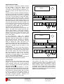
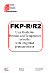
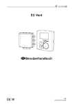
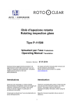
CONNECTION
The drive has two circuit boards with screw
clamps. On the lower row are the incoming
power terminals. These are L and N. Protective
earth is connected to the terminals marked with
the ground symbol .
Outgoing motor phases are marked U, V and W.
The motor thermal protection device (PTC type)
should be connected to the terminals marked Tk.
This terminal is a power terminal and is not safe
to touch or connect to low-voltage systems. If
the Tk terminals are not used, they must be
connected (shorted) together, otherwise the
drive will stop with a "Motor PTC" fault.
FRABIL
FRACON
GRUPPEN
Frabil El AB
Bjurögatan 38
211 24 Malmö
display
21 24 22
M+ M- 0 1 2 3 4 5 6 7 8 9 10 11 12
Alarm
Start/stop
L
N
U
V
W
Tk
Incoming
230VAC
Tk
Tk
M
Figure 1: Connections for 0-10V reference and
running forwards.
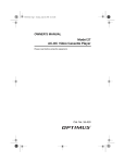
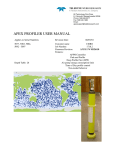
display
From smoke
detector
21 24 22
M+ M- 0 1 2 3 4 5 6 7 8 9 10 11 12
Alarm
Start/stop
L
N
NTC
U
V
Incoming
230VAC
W
Tk
Tk
Tk
M
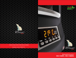
Figure 2. Connection for pressure control with
fixed frequency activated by smoke detector.
This product can cause a D.C. current in the
protective conductor. Where a Residual Current
Device (RCD) is used for protection in case of
direct or indirect contact, only an RCD of Type B
is allowed on the supply side of this product.
Otherwise, another protective measure shall be
applied such separation from the environment by
double or reinforced isolation.
Telefon: 040-28 70 90
Fax: 040-18 47 09
www.frabil.se
4
The upper circuit board is galvanically isolated
from the incoming phases. All signal and control
cables are connected to screw clamps on this
board.
Terminals 21 to 24 are connected to the alarm
relay. They are fully isolated from all other
voltages within the drive, and are capable of
switching 8A at 250VAC. Terminals 21 and 24
are connected by the relay when the drive is free
of faults. Terminals 21 and 22 are connected
when there is an alarm or the drive is not
powered.
Terminals M+, M- and 0 are the MODBUS
terminals. M+ corresponds to MODBUS D1 or B,
while M- is D0 or A. 0 is the MODBUS common
ground potential.
A 10V reference voltage is available on terminal
1. Terminal 2 is the 0-10V frequency reference
input. It can also be used to connect an external
active temperature sensor. When used as a
frequency
reference,
the
frequency
is
proportional to the input voltage.
Signal common is available on terminals 3,8,10
and 12. Signal common is for EMC reasons
connected to protective earth through a 40nF
capacitor and a 100kohm resistor.
Terminals 4 and 6 are 24V digital inputs.
Connecting 24V to terminal 4 makes the motor
run forwards. Connecting 24V to terminal 6
either makes the motor run in reverse, or makes
the motor run at a fixed frequency. Which
depends on the setting of "System settings/Use
fixed freq.".
A 24V output is available on terminal 5.
Terminal 7 is a 0-10V analog input which can be
used to connect an external pressure sensor.
Terminal 9 is used to connect an external
passive NTC thermistor. It can also be used to
connect an optional PT1000 adapter.
Terminal 11 is a 4-20mA output, which may be
loaded with 0-750 ohms. The function of the
output is chosen with the setting "System
settings/4-20mA output". The choices are
measured pressure or motor frequency. The
values are scaled such that the maximum value
of the signal corresponds to 20mA and zero to
4mA. If the internal pressure sensor is used, the
pressure range of the output is 0-1000Pa.
If you wish to customize the function of these
terminals, do not hesitate to contact us.
FRABIL
FRACON
GRUPPEN
Frabil El AB
Bjurögatan 38
211 24 Malmö
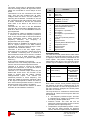
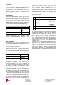
Terminal
Nr
21
24
22
M+
M0
1
2
3
4
5
6
7
8
9
10
11
12
Function
Alarm Common
Alarm OK
Alarm Fault
MODBUS+ (B or D1)
MODBUS- (A or D0)
MODBUS Common
10V Reference
0-10V IN 1 (frequency/external
active temperature sensor)
Signal common
24V Digital In 1 (forward)
24V Output
24V Digital In 2 (reverse/fixed
frequency)
0-10V IN 2 (external pressure
sensor)
Signal common
External passive NTC/PT1000
temperature sensor
Signal common
4-20mA OUT
Signal common
DRIVE SETTINGS
The FKP has several presets built in which make
setting up a drive both faster and safer. A preset
is a group of values for all the parameters in the
menu system. They allow configuring all the
parameters of the drive in a few seconds. Not all
presets may be available in all types of the drive.
DRIVE SETTINGS:
Nr:
Parameter:
18 Preset setting
36
Control method
Value:
Custom,
50Hz Standard,
50Hz Fan
0 - 10V ref,
Pressurecont.,
Tempcomp
Pr.cont, Temp.
contr
Note: When chosen, these presets change all
the settings of the drive, including those of the
pressure controller. As soon as any parameter in
the menu system is changed, the chosen preset
will return to "Custom".
The way the drive is controlled is selected with
parameter 36. There are four ways the FKP can
be controlled:
0 - 10V frequency reference input. The FKP
is controlled by a voltage on terminal 2, like
an ordinary variable speed drive.
Pressure control. The FKP will use an
external or internal pressure sensor to control
pressure with its output frequency.
Temperature compensated pressure control.
This has the same function as pressure
control, with the exception that a temperature
Telefon: 040-28 70 90
Fax: 040-18 47 09
www.frabil.se
5
sensor is used to compensate the reference
pressure.
Temperature control. Controls the motor
frequency using a temperature signal.
0 - 10V REFERENCE
The alternative "0 - 10V reference" in parameter
36 sets the drive to be controlled by a 0 - 10V
reference like an ordinary variable speed drive.
In this mode, 0V on terminal 2 corresponds to
minimum motor frequency (parameter 8), and
10V corresponds to maximum motor frequency
(parameter 7).
PRESSURE CONTROL
The FKP is equipped with a built in pressure
controller, and a pressure sensor with a range of
-1000 - 1000Pa. To use this controller, select
"Pressurecont." in parameter 36 ("Control
method").
It is also possible to use an external pressure
sensor with the FKP. Such a sensor should be
designed to emit a 0 - 10V signal proportional to
pressure.
The internal pressure sensor has two external
5mm hose connections. The positive side
(where overpressure reads as a positive
pressure) is marked with a (+) next to the
connection.
Setting up the FKP pressure controller is simple
and fast. The pressure controller is of PI-type. Its
gain is set with parameter 20, and its integration
time with parameter 21. If an integration function
is not desired, set the time to 0.
The reference pressure of the controller is set
with parameter 19. The output of the controller
(which is the motor frequency) is limited by the
maximum and minimum motor frequency limits
(parameters 7 and 8). It is also limited by the
ramp times, parameters 9 and 10. Note that
parameter 7 to 10 are located in the "Motor
settings" menu, and that they affect the
operation of the drive in all modes.
PRESS/TEMP. SETTINGS:
(Pressure controller settings)
Nr:
Parameter:
Value:
Pressure ref (external)
0 - 1500Pa
19
(internal)
0 - 950Pa
20
Controller gain Kp
21 Integ. time Ti
22 Press. input
24 Ext. min press.
26 Ext. max press.
27 Zero pressure
0 - 999
1 - 999
Internal,
External
-1500 - 0Pa
0 - 1500Pa
Yes, No
Parameter 22 is used to select the type of
pressure sensor in use, internal or external.
The pressure sensor (internal or external) can
be calibrated by setting the zero pressure point.
This is done by selecting "Yes" on parameter 27
when there no difference in pressure applied to
the pressure inputs. The FKP will use the
measured pressure as the new zero pressure
point. The internal sensor is calibrated from the
factory and usually does not require further
calibration.
If an external sensor is to be used, the pressure
corresponding to 0V should be set in parameter
24, and the pressure corresponding to 10V in
parameter 26. This should always be followed by
a zeroing of the pressure as described above.
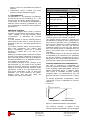
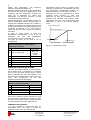
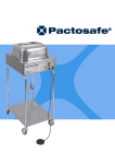
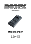
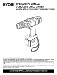
OUTSIDE TEMPERATURE COMPENSATION
The FKP is equipped to compensate for
pressure changes in ventilation systems caused
by the changing outside temperature. When the
outside temperature drops, a chimney effect
often occurs in ventilation channels, causing
increased airflow. To compensate for this, the
pressure reference is lowered as seen in figure
3.
To activate temperature compensation, select
"Tempcomp. Pr.cont" in parameter 36 ("Control
method").
Pressure reduction
Pressure (Pa)
Pressure reference
Temperature (°C)
Min Temperature
Max Temperature
Figure 3. Outside temperature compensation.
The pressure reduction is applied to the
reference pressure (parameter 19), and changes
FRABIL
FRACON
GRUPPEN
Frabil El AB
Bjurögatan 38
211 24 Malmö
Telefon: 040-28 70 90
Fax: 040-18 47 09
www.frabil.se
6
linearly with temperature. The maximum
reduction is set with parameter 35.
Pressure reduction starts when the temperature
drops below the value set in parameter 34, and
continues until the temperature reaches the
value set in parameter 33. Below that
temperature, the pressure reference is held
constant at maximum reduction.
Outside temperature compensation requires an
external temperature sensor. Several types of
sensors are compatible with the FKP. (4FKP-T1)
100kohm and (4FKP-T2) 10kohm NTC sensors
and PT1000 sensors (with optional adapter) are
connected to terminal 9. An active (0-10V)
sensor can also be used, it is then connected to
terminal 2.
In case an active sensor is used, the
temperature corresponding to 0V is set in
parameter
30,
and
the
temperature
corresponding to 10V in parameter 32.
The type of sensor to be used is set in
parameter 28.
PRESS/TEMP. SETTINGS:
(Outside temperature compensation /
Temperature control)
Nr:
Parameter:
Value:
NTC 100k,
NTC 10k,
28 Temp. sensor type
PT1000,
Active
30 Active temp. min
-50 - 0°C
32 Active temp. max
0 - 100°C
33 Temperature min.
-50 - 50°C
34 Temperature max.
-50 - 50°C
35 Press. reduction
0 - 500Pa
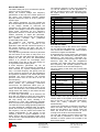
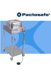
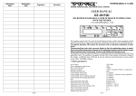
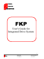
Temperature control works by changing motor
frequency proportional to temperature, just like
how temperature compensation changes the
pressure reference. This is shown in figure 4.
Parameter 34 sets the temperature at which
maximum motor frequency is used, and
parameter 33 sets the temperature for the
minimum. The maximum and minimum motor
frequencies are set in the usual manner with
parameters 7 and 8 in the "Motor settings"
menu.
Motor frequency (Hz)
Max motor frequency
Min motor frequency
Min Temperature
Temperature (°C)
Max Temperature
Figure 4. Temperature control.
PRESSURE CONTROLLER ALARMS
The FKP will always indicate a pressure alarm
via the alarm relay. If parameter 37 is selected
(set to 'yes'), the drive will also stop on these
alarms. Otherwise the drive will continue to run
the motor during these alarms. Alarm limits for
under- and overpressure are set with
parameters 38 and 39 respectively.
PRESS/TEMP. SETTINGS:
(Pressure controller alarms)
Nr:
Parameter:
Value:
37 Stop on alarm
Yes/No
38 Alarm upper lim.
-1500 - 1500Pa
39 Alarm lower lim.
-1500 - 1500Pa
40 Alarm delay
0 - 1000s
To prevent the pressure alarms from tripping
during short pressure pulses (caused by wind
etc), the alarms are delayed. In order to cause
an alarm, the pressure must be outside the limits
for longer than the time set in parameter 40.
TEMPERATURE CONTROL
It is also possible to control the FKP by
temperature only. This mode is chosen by
selecting "Temp. contr" in parameter 28.
FRABIL
FRACON
GRUPPEN
Frabil El AB
Bjurögatan 38
211 24 Malmö
Telefon: 040-28 70 90
Fax: 040-18 47 09
www.frabil.se
MOTOR SETTINGS
The FKP is easily set up to work with the specific
motor it is to be connected to.
Simply set nominal voltage and frequency
(parameters 14 and 15) to the values printed on
the motor. The maximum nominal voltage
depends whether the drive is of the 1-phase or
3-phase type.
"Min voltage" (parameter 13) is the voltage the
drive would output at 0 Hz motor frequency. This
is the voltage needed to overcome the
resistance in the motor and make it turn at low
speeds. This voltage is used as a compensation
factor which decreases as the frequency
approaches nominal. In actual use with fans it is
seldom necessary to adjust this parameter.
However, if the fan does not turn as intended at
low
speeds,
increase
this
parameter
incrementally until it does.
Set maximum and minimum frequencies
(parameters 7 and 8) as required in the
application. Note that the minimum frequency is
the lowest frequency the drive will run at
continuously. The drive will always ramp from 1
Hz at startup.
The ramp times (parameters 9 and 10) describe
the time taken for the drive to ramp from 0 to
50Hz or 50 to 0Hz. Note that if the down ramp is
slightly too fast, the drive will automatically
extend it to prevent an overvoltage fault.
Overvoltage occurs due to the motor being run
as a generator while ramping down.
A fixed frequency (parameter 42) can be
chosen, which will be activated by terminal 6
when selected by "System settings/Use fixed
freq.". The fixed frequency has priority over the
0-10V reference input and over the temperature
and pressure controllers. This means that when
activated, the fixed frequency will override
pressure control and run the drive at the set
fixed frequency.
The drive has a built-in motor protection circuit
which works by preventing continuous
overcurrents. The parameter "Motor prot." (nr.
11) should be set to the nominal current of the
motor. The drive has a 10% continuous overload
margin above this setting. It also allows shorter
overloads beyond this limit.
If "Coast stop" (parameter 12) is selected, the
drive will not attempt to ramp the motor down
when the start signal is disconnected. Rather, it
will stop driving the motor, allowing it to
freewheel to a halt. This parameter generally
does not need to be changed in fan applications.
The FKP has several voltage profiles (parameter
16), each adapted to a different load. The linear
profile will increase the voltage proportionally to
the frequency. The fan profile will increase the
voltage proportionally to the square of the
frequency, which is a good adaptation to fan
loads. There is also an automatic profile, which
can be useful in special applications with varying
load on the motor.
FRABIL
FRACON
GRUPPEN
Frabil El AB
Bjurögatan 38
211 24 Malmö
7
The switching frequency of the drive (parameter
17) can be altered to suit the application. In
general, a higher frequency will mean less noise,
but higher losses and more electromagnetic
interference.
MOTOR SETTINGS:
Nr: Parameter:
Value:
7
Max freq.
0 - 200Hz
8
Min freq.
0 - 200Hz
9
Ramp up time
1 - 600sek
10 Ramp down time
1 - 600sek
42 Fixed freq.
0 - 200Hz
11 Motor prot.
0 - 8.8A
12 Coast stop
On, Off
13 Min voltage
0 - 50V
14 Nom. voltage
0 - 230/400V
15 Nom. frequency
0 - 200Hz
16 Voltage profile
Linear, Fan, Auto
17 Switching freq.
5 - 14kHz
SYSTEM SETTINGS
The language used in the drive's menu system
can be changed with parameter 1, "Language".
Two choices are available in the current version
of the drive, English and Swedish.
A fixed frequency can be chosen with parameter
42, which will be activated by terminal 6 when
selected by "Use fixed freq." (parameter 43).
The fixed frequency has priority over the 0-10V
reference input and over the temperature
controller. This means that when activated, the
fixed frequency will override pressure control
and run the drive at the set fixed frequency.
The error history of the drive can be reset with
"Reset logs".
SYSTEM SETTINGS:
Nr:
Parameter:
Value:
1 Language
Swedish, English
43 Use fixed freq.
Yes, No
Motor frequency,
44 4 – 20mA output
Pressure
4 System log
Days and Hours
5 System error log
Se error screen
6 Drifts information
Type, firmware
2 Reset logs
Yes, No
3 System states
System data
45 Sys freezeframe
System data
"System states" and "Sys freezeframe" show the
internal state of the system at the present time
and at the time of the last fault respectively.
These are mainly intended for factory
troubleshooting.
"System log" (parameter 4) shows the number of
hours the drive has been running (with start
signal and not faulted). The counter cannot be
reset, but shows the total number of hours
running since the drive was manufactured.
The type and software revision date of the FKP
can be read in parameter 6, "Drive info". An
indication of which options are included in the
drive is also shown.
Telefon: 040-28 70 90
Fax: 040-18 47 09
www.frabil.se
8
FAULTS AND ALARMS
If a fault occurs, it is always shown on an error
screen. The faults are divided into three
categories.
The following faults are in the first category:
"Phase fault", which occurs when an
incoming phase or neutral is interrupted, or
when the input voltage is very low.
"Over voltage", which occurs when the drive's
DC voltage is too high. This may occur during
grid surges, or when the down ramp is set
too fast for the mass of the fan.
The drive will restart automatically 60 seconds
after any fault in the first category ceases. The
countdown to restart is shown on the screen.
The drive will restart an unlimited number of
times after faults in the first category.
If the fault persists, the drive will go into alarm
mode after 60 seconds. This will be indicated by
the text "Drive alarm!", and by the alarm relay
changing to the fault state. Once the drive is in
alarm mode, it can only be brought out of it by
pressing the encoder wheel, or by interrupting
the power to the drive long enough for it to turn
itself off (15-30 seconds normally).
The second category works exactly like the first,
with the exception that only 5 restarts are
allowed before the drive goes into alarm mode.
The faults in the second category are:
"Over load" occurs when the drive is
subjected to a current of more than 150% of
its nominal value.
"Over temp." occurs when the temperature in
the power components of the drive exceed
90°C.
The third category of faults bring the drive
directly to alarm mode, and consists of the
following faults:
"Motor prot." is triggered when the motor
current is more than 10% higher than the
setting of the parameter "Motor
settings/Motor prot." for an extended period.
The time to fault will be shorter the higher the
overcurrent is.
If a PTC-type thermal protection device is
connected to the 'Tk' terminal, it will cause
the fault "Motor PTC" when it overheats.
In pressure controlled mode, the drive will
also be subject to "Over press." and "Under
press." faults. These occur when the
pressure is too high or too low compared to
the settings of the pressure controller. These
faults are special in that they can be set to
not stop the drive. This is controlled by the
"Press./Temp. settings/Stop on alarm".
To aid in troubleshooting, the FKP will record all
faults for later viewing. This recording will not be
reset by loss of power to the drive. The faults are
shown in the "System settings/System error log"
parameter. The first items shown are the total
count of errors of each type that have occurred.
Below the separating line, the last 8 faults are
shown. The most recent fault is shown at the
FRABIL
FRACON
GRUPPEN
Frabil El AB
Bjurögatan 38
211 24 Malmö
top. Each fault has a number to shown how
many faults have occurred in total. (For
example, the third fault to have occurred is
numbered 3.)
It is possible to reset the error history of the drive
using the "System settings/Reset logs"
parameter. This will have no other effect on the
drive.
In the unlikely event that a fault occurs when
reading from the memory where the drive's
settings are stored, the screen will show "Error
reading EEPROM data. Default settings used."
All drive settings will then return to factory
defaults. If the error occurs more than once,
contact service.
DRIVE STOPPED
If a start signal is not connected to either
terminal 4 (forward) or 6 (reverse), the display
will show the drive stopped screen. The menus
can as always be accessed by turning the
encoder wheel.
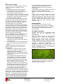
INFORMATION SCREEN
The FKP shows many types of information while
running,
to
aid
in
diagnostics
and
troubleshooting.
When the drive is active (a start signal is
connected, and no faults have occurred), the
display will show relevant status information.
Output frequency, motor current, and output
voltage will always be shown. If pressure control
is selected, the screen will also show the current
pressure. If temperature compensation
or
temperature control is selected, the current
outside temperature will also be shown. If no
control is selected, the 0 - 10V frequency
reference value will be shown.
Figure 5. Information screen in pressure
controlled mode with temperature compensation.
The built-in timer is active and is reducing the
pressure reference by 80%.
Telefon: 040-28 70 90
Fax: 040-18 47 09
www.frabil.se
9
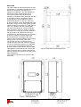
MOUNTING
The FKP is water and dust protected up to IP54
classification. It is quickly and easily mounted on
almost any flat surface. See Figure 6 for
mounting hole drill plan. The hole diameter on
the FKP is 5.5mm, and the holes have a
convenient keyhole shape to allow quick
mounting. To maintain water protection, the seal
on the hatch must be undamaged, and the
screws tightened. Never attempt to open or
disassemble the drive in any way other than
opening the hatch, as this will damage the water
protection. Always use the cable glands to pass
cables through the enclosure. If a cable gland is
not in use, replace it with the provided plug.
The drive must always be mounted vertically
when mounted in free air, in order to maintain
convection for cooling. Allow at least 100mm of
free space above and below the FKP when
mounted thusly. Mounting the drive in the airflow
of the fan it controls is recommended, and
allows mounting in orientations other than
vertical. In any mounting situation, good cooling
will improve the service life of the drive.
The reverse side of the connection hatch
contains a quick connection reference. Always
use short conductors inside the unit, especially
on the incoming and outgoing phases and
protective earth. Always use the included EMC
cable gland to connect the screen of the motor
cable. Excessive slack on these conductors or
faulty connection of the cable screen may cause
radio interference.
The pressure connections are sized for 5mm
PVC hose.
Figure 6. Drill plan and outer dimensions.
Figure 7. FKP dimensions.
FRABIL
FRACON
GRUPPEN
Frabil El AB
Bjurögatan 38
211 24 Malmö
Telefon: 040-28 70 90
Fax: 040-18 47 09
www.frabil.se
10
OPTIONS
The FKP can be equipped with several options
in order to provide a complete ventilation control
solution. MODBUS/RTU or Ethernet IP allows
easy monitoring and remote control. A built-in
timer allows control of the drive's pressure or
frequency reference based on time-of-day and
weekday.
MODBUS/RTU
With the RS485 MODBUS option, the FKP can
communicate with a MODBUS master using
MODBUS/RTU. Essentially all the settings that
can be changed via the menu system can also
be changed via MODBUS. See the MODBUS
Data Dictionary for more information, or contact
us if you wish to customize the available data.
MODBUS SETTINGS:
Nr: Parameter:
50 MODBUS address
51
MODBUS parity
52
MODBUS baudrate
Value:
1 - 247
None, Even,
Odd
2400, 4800,
9600, 19200
MODBUS parameters are available under
"System settings/MODBUS settings", and
consist of address, parity and baudrate (bitrate).
BUILT-IN TIMER
The optional built-in Real Time Clock (RTC)
allows lowering the reference value of the drive
(be it pressure, temperature or frequency) based
on almost arbitrary schedules.
The RTC has a backup battery to allow it to keep
track of the time even when the FKP has no
external power applied. The current time and
day is set with parameter 56 and 55 respectively
(under "System settings").
System clock:
Nr: Parameter:
55
System clock
56
System clock
07:00, the program will run from 14:00 on
Monday until 07:00 on Tuesday.
The reference value (parameter 54) is
expressed as a percentage of the active
reference value of the drive. For example, if the
drive has a pressure reference of 100Pa, and
the timer program reference is 70%, then the
drive will use a 70Pa reference while the
program is running.
TIMER SETTINGS:
Nr: Parameter:
50 Chosen program
51
Run Px on
52
53
54
Start time for Px
Stop time for Px
Refvalue of Px
Value:
P1 - P7
No days,
Mon - Sun,
Weekdays,
Weekends,
All days
00:00 - 23:59
00:00 - 23:59
0 - 100%
If several programs are scheduled to run with
overlapping times, the program with the highest
number will take priority. For example, if P1 is
set from 12:00 to 17:00 with reference 30%, and
P7 is set from 15:00 to 16:00 with reference
10%, then the drive will run with 30% reference
from 12:00 to 15:00, with 10% reference from
15:00 to 16:00, and with 30% reference from
16:00 to 17:00.
In case one or more programs are active but not
performing any reference reduction presently
(that is, not scheduled to run at this time), the
information screen will show "P*" in the lower
right corner. When a program is running and
reducing the reference, the screen will show the
program number and the reference reduction (as
seen in Figure 5).
Value:
Monday Sunday
hh:mm:ss
The weekly schedule is set under "Timer
settings" by first choosing one of seven available
programs (parameter 50). This is followed by
choosing the start and stop times, the day to run
the program, and the reference value while
running it. From the factory, all programs are
deactivated by setting "Run Px on" (parameter
51) to "No days".
The starting time is set with parameter 52, and
the stop time with parameter 53. If the stop time
is set before or the same as the start time, the
program will run from the start time on the
chosen day, to the stop time on the next day.
For example, if the chosen day is Monday, the
starting time is 14:00, and the stopping time is
FRABIL
FRACON
GRUPPEN
Frabil El AB
Bjurögatan 38
211 24 Malmö
Telefon: 040-28 70 90
Fax: 040-18 47 09
www.frabil.se
11
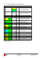
Appendix A. QUICK REFERENCE TO FKP MENU SYSTEM
DRIVE SETTINGS:
Nr:
Parameter:
Value:
0 - 10V ref,
36 Control method
Pressurecont.,
Tempcomp
Pr.cont
Description:
Default:
Choose the way the drive is controlled. Choices
are 0 - 10 V frequency reference; Pressure
0-10V ref
control with or without temperature
compensation; Temperature control only.
Temp. contr
18 Preset setting
Custom,
50Hz Standard,
50Hz Fan
-
Preset setting of entire drive, changes both
motor and pressure parameters. Returns to
Custom as soon as any other parameter is
changed.
PRESS/TEMP. SETTINGS:
Nr:
19
Parameter:
Pressure ref (external)
(internal)
35 Press. reduction
Description:
Value:
Default:
0 - 1500Pa
0 - 950Pa
100Pa
Pressure reference of the controller, also
shows actual value and pressure reference
value after temperature compensation.
0 - pressure ref.
(Pa)
15Pa
Magnitude of the decrease of the pressure
reference at the lower temperature
compensation corner point.
33 Temperature min.
-50 - 50°C
15°C
Upper corner point for temp. comp.
34 Temperature max.
-50 - 50°C
-15°C
Lower corner point for temp. comp.
Yes, No
Yes
38 Alarm upper lim.
-1500-1500Pa
999Pa
Alarm limit for overpressure.
39 Alarm lower lim.
-1500-1500Pa
-10Pa
Alarm limit for underpressure.
0 - 1000s
100sek
Time until a pressure alarm is generated.
37 Stop on larm
40 Alarm delay
28 Temp. sensor type
"Yes" will stop the drive (and activate the alarm
relay) on pressure alarms, "No" will only
activate the alarm relay.
NTC 100k,
Type of temperature sensor (active sensors are
NTC 10k,
NTC 100k
connected to terminal 2).
PT1000, Active
30 Active temp. min
-50 - 0°C
-40°C
Temperature with 0V from active sensor.
32 Active temp. max
0 - 100°C
Internal,
External
80°C
Temperature with 10V from active sensor.
22 Press. input
Internal
Pressure sensor type.
24 Ext. min press.
-1500 - 0Pa
0Pa
Pressure with 0V from external sensor.
26 Ext. max press.
0 - 1500Pa
999Pa
Pressure with 10V from external sensor.
27 Zero pressure
Yes, No
-
20 Controller gain Kp
0 - 999
0
21 Integ. time Ti
1 - 999
400
Calibrate actual pressure to zero now.
Gain applied to the difference between the
actual and reference pressures.
Controller integration time.
The colors mark which parameters are active dependant on the choice of
Control method
FRABIL
FRACON
GRUPPEN
Frabil El AB
Bjurögatan 38
211 24 Malmö
Telefon: 040-28 70 90
Fax: 040-18 47 09
www.frabil.se
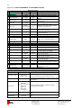
12
Appendix A. QUICK REFERENCE TO FKP MENU SYSTEM
MOTOR SETTINGS:
Nr:
Parameter:
7 Max motor freq.
Description:
Value:
0 - 200Hz
Default:
50Hz
Upper limit for motor frequency.
0 - 200Hz
1Hz
9 Ramp down time
1 - 600s
60s
10 Ramp up time
1 - 600s
60s
42 Fixed freq.
0 - 200Hz
50Hz
Lower continous limit for motor frequency
Minimum acceleration time to 50Hz motor
frequency.
Minimum decceleration time from 50Hz
motor frequency.
Fixed motor frequency, used when setting 43
is "Yes" and terminal 6 is high.
11 Motor prot.
0.7A to
nominal current
0.7A
12 Coast stop
On, Off
Off
13 Min voltage
0 - 50V
20V
0 - 230/400V
230/400V
0 - 200Hz
50Hz
Nominal (rated) frequency of the motor
16 Voltage profile
Linear,
Fan,
Auto
Linear
Relation between motor frequency and
voltage. "Fan" is especially adapted to fan
drives.
17 Switching freq.
5 - 14kHz
12.5kHz
Nr:
Value:
Swedish,
English
8 Min motor freq.
14 Nom. voltage
15 Nom. frequency
Rated motor current, drive will trip if this is
exceeded by more than 10%.
"On" will allow the motor to coast to a stop,
"Off" will brake it electically.
Lowest voltage the drive will give out. Also
sets I/R kompensation.
Nominal (rated) voltage of the motor.
Switching frequency of the drive.
SYSTEM SETTINGS:
Parameter:
1 Language
43 Use fixed freq.
Swedish
Yes, No
No
Motor freq,
Pressure
Motor
frequency
Days and hours
-
See error
screen
-
6 Drive info
Type, firmware
-
2 Reset logs
Yes, No
-
3 System states
System data
-
45 Sys freezeframe
System data
-
44 4 - 20mA output
4 System log
5 System error log
Description:
Default:
Menu system language.
Fixed motor frequency is used when setting
43 is "Yes" and terminal 6 is high.
The signal output on the 4-20mA output. For
scaling, see the manual.
Shows the time the drive has been running
with start signal connected.
Shows the count of each type of fault, and
the 8 most recent faults.
The type, manufacturer, firmware revision
date, power rating and options of the drive.
Resets the system error log.
Shown many of the internal variables of the
system (for service use).
Service use.
STATUS SCREENS:
Screen:
Information screen
Code screen
Error screen
Values:
Pressure/temp/ref,
Freq., timer,
Voltage, Current
Menu code
Drive stopped text
EEPROM error
Error text
FRACON
GRUPPEN
Always shown in when drive is running. Showns "P*" or
"xx% Px" if the drive has an active timer function.
Gives access to the parameters of the drive, see the inside
of the hatch lid.
Over voltage,
Phase fault,
Over load, Over temp,
Shows drive faults and alarms. Alarms are reset by
Motor prot.,
pressing the encoder wheel.
Motor PTC,
Over press.,
Under press.
Stopped screen
FRABIL
Description:
Shown when the drive is stopped due to missing start
signal.
Shown when the internal memory of the drive can not be
read.
Frabil El AB
Bjurögatan 38
211 24 Malmö
Telefon: 040-28 70 90
Fax: 040-18 47 09
www.frabil.se
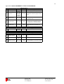
13
Appendix B: QUICK REFERENCE TO FKP OPTIONS MENUS
TIMER SETTINGS:
Parameter:
Value:
Default:
50 Chosen program
P1 - P7
P1
51 Run Px on
No days,
Mon. - Sun.,
Weekdays,
Weekends,
All days
No days
52 Start time for Px
00:00 - 23:59
00:00
Choose which time on the chosen day
the program starts.
53 Stop time for Px
00:00 - 23:59
00:00
Choose which time the program stops. If
the chosen time is before the start time,
the program will run until the next day.
54 Ref value for Px
0 - 100%
100%
Percentage of pressure or frequency
reference used when the program is
active.
Nr:
Description:
Choose a program to change
Choose which days the program should
run on.
CLOCK SETTINGS: (under System Settings)
MondaySets the current day
Sunday
hh:mm:ss
Sets the current time of day
55 System clock
56 System clock
MODBUS SETTINGS: (under System Settings)
Parameter:
Nr:
Value:
Default:
1 - 247
1
58 MODBUS parity
None, Odd,
Even
Even
Choose MODBUS parity.
59 MODBUS baudrate
2400, 4800,
9600, 19200
19200
Choose MODBUS communication bitrate.
57 MODBUS address
FRABIL
FRACON
GRUPPEN
Description:
Choose the MODBUS address of this
drive.
Frabil El AB
Bjurögatan 38
211 24 Malmö
Telefon: 040-28 70 90
Fax: 040-18 47 09
www.frabil.se
FRABIL
FRACON
GRUPPEN
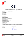
Tillverkardeklaration EMC och Elsäkerhet
(Declaration of Conformity)
PRODUKT
FKP frekvensomriktare 0.37-2.2kW 230V
TILLVERKARE
Frabil El AB
Bjurögatan 38
21124 Malmö
Tfn. 040 - 28 70 90
DIREKTIV EMC
2004/108/EC
NORMER EMISSION
EN 61000-6-3:2001
EN 55022:1998, A1:2000, -A1 Class B
NORMER IMMUNITET
EN 61000-6-2:2005
EN 61000-4-2, -3, -4, -5, -6, -11
DIREKTIV ELSÄKERHET
2006/95/EC (LVD)
NORMER
EN 50178:1997
Tillverkaren försäkrar på eget ansvar att den produkt som denna försäkran avser
överensstämmer med de krav som anges i ovan angivna EU-direktiv.
DATUM
2007-09-17
UNDERSKRIFT
Hans Fransson
FRABIL
FRACON
GRUPPEN
Frabil El AB
Bjurögatan 38
211 24 Malmö
Telefon: 040-28 70 90
Fax: 040-18 47 09
www.frabil.se
15
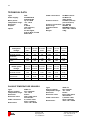
TECHNICAL DATA
Type:
Power supply:
Motor power:
Temperature range:
Enclosure:
Outputs:
Inputs:
230V phase
voltage:
Nominal current:
Continous
overcurrent:
Fuse:
3x400V phase
voltage:
FKP
230VAC/50Hz
3x400V/50 Hz
up to 2.2kW
-25 - +40°C
IP54
4-20mA,
10V reference,
2x 0-10V,
2x 24V digital,
Analog NTC, PT1000
Motor PTC
Cable connections:
2st M20×1,5 and
2st M16×1,5
cable glands
Pressure sensor:
±1000Pa (internal)
(1Pa resolution)
Pressure connection: Two 5mmØ
Alarm relay:
250VAC, 8A
Communication:
MODBUS (option)
Size:
310 x 185 x 135mm
Weight:
3.8kg
0,37 kW/ 0,55 kW/ 0,75 kW/
230V
230V
230V
1,1 kW/
230V
1,5 kW/
230V
2,2 kW/
230V
2A
3A
4A
5,5A
7A
9A
2,2A
10A
3,3A
10A
4,4A
10A
6A
16A
7,7A
16A
9,9A
20A
1,1 kW/
3x400V
1,5 kW/
3x400V
2,2 kW/
3x400V
0,37 kW/ 0,55 kW/ 0,75 kW/
3x400V 3x400V 3x400V
Nominal current:
1,6A
2,0A
2,5A
3,3A
4,1A
5,6A
Continous
overcurrent:
Fuse:
1,7A
10A
2,2A
10A
2,7A
10A
3,6A
10A
4,5A
10A
6,1A
10A
PASSIVE TEMPERATURE SENSORS
Type:
Sensor element:
Temperature range:
Enclosure:
Enclosure class:
Cable connection:
Dimensions:
FRABIL
FRACON
GRUPPEN
4FKP-T1
NTC 100kohm
-39 - +50°C
Plastic
IP54, cable gland
downwards
2,1m PVC cable
2wire x 0,5mm2
100 x 100 x 38mm
Frabil El AB
Bjurögatan 38
211 24 Malmö
Type:
Sensor element:
Temperature range:
Enclosure:
Enclosure class:
Cable connection:
Dimensions:
4FKP-T2
NTC 10kohm
-39 - +50°C
Plastic
IP54, cable gland
downwards
2,1m PVC cable
2wire x 0,5mm2
100 x 100 x 38mm
Telefon: 040-28 70 90
Fax: 040-18 47 09
www.frabil.se
16
Notes
FRABIL
FRACON
GRUPPEN
Frabil El AB
Bjurögatan 38
211 24 Malmö
Telefon: 040-28 70 90
Fax: 040-18 47 09
www.frabil.se
17
FRABIL
FRACON
GRUPPEN
Frabil El AB
Bjurögatan 38
211 24 Malmö
Telefon: 040-28 70 90
Fax: 040-18 47 09
www.frabil.se