Download ULS User Guide - Une

Transcript
Installation & Set-up Guide
VLS2.30, VLS3.50
www.ulsinc.com
Table of Contents
Proper Operating Environment
Environment…………………………………………………………………………………………………………………5
Electrical Power Source………………………………………………………………………………………………………6
Exhaust System.………………………………………………………………………………………………………………6
Diagram…………………………………………………………………………………………………………………7
Software Installation and Requirements
Computer and Operating System Requirements……………………………………………………………………………9
Universal Control Panel (UCP) Installation CD-ROM………………………………………………………………………11
Assembling Your VersaLASER® System
System Assembly - VersaLASER Systems……………………………………………………………………………………15
Finalizing the Connections…………………………………………………………………………………………………17
Checking Beam Alignment…………………………………………………………………………………………………20
Running Your First Job
Step 1 - Loading and Positioning the Material.……………………………………………………………………………21
Step 2 - Creating the Graphic………………………………………………………………………………………………21
Step 3 - Printing to Your VersaLASER® System.……………………………………………………………………………22
Step 4 - Starting the Process…………………………………………………………………………………………………23
Step 5 - Material Removal and Reloading.…………………………………………………………………………………23
3
Installation & Set-up Guide
Thank you for choosing Universal Laser Systems®. We appreciate innovative customers
like you who have made Universal Laser Systems an integral part of their business.
Universal Laser Systems is committed to providing the highest level of customer
satisfaction and support. To ensure your satisfaction, we urge you to read the
documentation contained within the Reference Guide and User Guide CD.
Since 1988, Universal Laser Systems has been committed to continually improving our
technology and customer-driven laser solutions. Your satisfaction is very important to
us and we welcome your feedback. Tell us about your experience with Universal Laser
Systems and our systems at [email protected]
Should you have any questions during your installation, please contact your local
representative or Universal Laser Systems’ Customer Service Team at 480-609-0297
(USA), +43 1 402 22 50 (Austria), +81 (45) 224-2270 (Japan) or e-mail us at support@
ulsinc.com.
Again, thank you for choosing Universal Laser Systems.
Your Universal Laser Systems Team
4
Proper Operating Environment
The Installation & Set-up Guide is designed to provide you with step-by-step instructions for proper
installation and set-up of your Universal laser system. Before getting started, you should become
familiar with each section of the Installation & Set-Up Guide: Proper Operating Environment Procedures,
Software Installation and Requirements, Assembling Your System and Running Your First Job.
Proper Operating Environment
This section will give you step-by-step instructions for site preparation and computer and software
setup. Follow the instructions in the order shown.
1. Establishing a Proper Operating Environment
2. Software Installation and Operating System Requirements
3. Assembling Your VersaLASER (VLS) System
4. Running Your First Job
CAUTION: Damage to the VLS system due to inadequate or improper operating environment is not
covered under the Universal Laser Systems (ULS) Warranty. See the ULS Warranty for additional
information. The ULS Warranty can be found in your Reference Guide booklet. Should you require a
copy of the Warranty, please contact your local Customer Service at 480-609-0297 (USA), +43 1 402
22 50 (Austria), +81 (45) 224-2270 (Japan) or e-mail us at [email protected].
Please refer to the Safety Manual before operating your laser system.
Environment (User Supplied)
1. The laser system must be installed in an office, laboratory, workshop or light duty
manufacturing environment. Dusty or dirty environments can damage the laser system.
Keep the laser system isolated from any processes hat produce airborne particles such as
sandblasting, sanding, machining, etc. Also, keep the VLS system isolated from any equipment
requiring mists of oil or water for lubrication. Airborne dust and liquids can coat and damage
optics and motion system components.
2. Avoid small, enclosed, non-ventilated areas. Some materials, after laser engraving or cutting,
continue emitting fumes for several minutes after processing. Having these materials present
in a confined, unventilated room can create a health hazard.
3. For best results, since the lasers are air-cooled, we recommend operating the laser system
between the ambient temperatures of 73ºF (22ºC) and 77ºF (25º C).
4. Avoid storing the laser system outside the temperatures of 50ºF (10ºC) and 95ºF (35º C) as
excessively cold or hot temperatures can damage the laser cartridge or reduce its lifetime.
5. Ambient humidity levels must be non-condensing to protect optics.
6. The laser system should be at least 2 feet (610 mm) away from any wall or obstruction.
5
Installation & Set-up Guide
Electrical Power Source (User Supplied)
1. For your system’s electrical requirements, please refer to the “INPUT POWER” label near the
power inlet.
2. CAUTION: Never remove the ground lead to the electrical cord and plug the VLS system
into a non-grounded outlet. A laser system that is not properly grounded is hazardous and
has the potential to cause severe or fatal electrical shock. Without proper grounding, the laser
system may exhibit sporadic or unpredictable behavior. Always plug the system into a properly
grounded (earthed) outlet.
3. Noisy or unstable electricity and voltage spikes may cause interference and possible damage
to the electronics of the laser system. If electrical power fluctuations, brown outs or constant
power outages are a problem in your area, please contact your local Electrician to supply a
power isolation and regulation module. Electrically noisy equipment, such as equipment with
large motors, can also cause interference if plugged into the same outlet. It may be necessary
to attach the laser system to a dedicated electrical line to resolve the problem.
4. The laser system is designed as a Class I, Group A, pluggable device. It is also designed for
connection to IT power systems which provide the most flexibility to the user.
Exhaust System (User Supplied)
1. We recommend you consult with a licensed contractor to meet local safety and building code
requirements.
2. The exhaust system must be capable of supplying a minimum of:
• VLS2.30 - 150 CFM (cubic feet per minute) of airflow while under a load of 6 inches of
static pressure (254m3/hr at 1.5kPa)
• VLS3.50 - 250 CFM (cubic feet per minute) of airflow while under a load of 6 inches of
static pressure (425m3/hr at 1.5kPa)
3. Do not install forward incline, backward incline, in-line or ventilator fans because these types
of air handlers are inadequate and inappropriate for this type of installation. A high-pressure
blower must be used to meet minimum airflow requirements.
4. For personal safety and noise control, we recommend that the exhaust blower be mounted
outside the building.
5. Rigid tubing should be used for the majority of the connection between the blower and
the laser system. The tubing should be smooth-walled and have as few 90-degree bends as
possible.
6. Install an exhaust gate to adjust airflow and to close off the exhaust when the laser is not in use.
Place this gate near the laser system within 5 to 10 feet (1.50 to 3.00 meters).
7. Use a short piece of industrial grade, wire-reinforced rubber tubing to connect the laser
system’s exhaust port to the exhaust gate and secure with a hose clamp. This will provide some
mobility for your laser system and will isolate exhaust blower vibrations from your laser system.
8. Wire the exhaust blower electrically to a wall switch in the same room for easy ON/OFF control.
6
Proper Operating Environment
Note: The following diagram shows a typical exhaust system layout. Use this as a guideline for proper
exhaust system installation. Although this diagram serves as an example, we recommend you consult
with a licensed contractor to meet local safety, environmental and building code requirements and to
also calculate the correct size blower required for your particular installation. Length of exhaust pipe,
exhaust pipe diameter, number of 90-degree angles and other restrictions must be calculated when
determining the correct exhaust blower unit. Installing an undersized or oversized blower is not only
unsafe, but can also lead to excessive wear and tear to the laser system and premature failure.
VLS2.30 and VLS3.50
2
1
9
8
4
7
3
5
6
1. Exhaust blower mounted outside* (User Supplied)
2. Weatherproof shield (User Supplied)
3. Rigid ducting matching the diameter of the blower inlet (User Supplied)
4. Shut-off or air-flow gate (User Supplied)
5. Adapter to the hose reduces from 4” to 3” (User Supplied)
6. Flexible, wire-reinforced, industrial grade rubber hose (User Supplied)
7. Connection to laser system
8. Exhaust On/Off switch (User Supplied)
9. Computer (User Supplied)
*Exhaust blower illustration my differ according to your region.
7
Software Installation and Requirements
Your computer is a critical component in the operation of the VLS system. In fact, you cannot operate
the VLS system if your computer is not connected, powered on, running Windows and running the
Universal Control Panel (UCP) software.
You can only run one VLS system per computer at a time. You will need to have a separate computer for
each VLS system you own. The VLS system is not designed to be a network printer. You must operate
the VLS system using the computer that is directly attached to it via the provided 6-foot USB cable (1.82
meters). USB cables longer than 6 feet (1.82 meters) may cause the VLS system to malfunction.
Computer and Operating System Requirements
Minimum Computer Requirements (User Supplied)
• 2.0 GHz processor (minimum)
• Windows XP or Windows Vista*
• 1 GB of RAM (minimum); 2 GB of RAM (minimum) for Vista operating systems
• 40 GB hard drive (15 GB free space) (minimum)
• VGA monitor (minimum 1024 x 768 resolution)
• CD-ROM drive/burner
• Mouse and keyboard
• Available USB 2.0 Hi-Speed compliant port only
• Computer speakers (optional)
• 600 DPI scanner (optional)
• Internet connection and e-mail address (optional)
*The VLS system is only compatible with a 32-bit Windows Operating System. See www.microsoft.com for the minimum computer
requirements to run Windows Vista. The VLS system is not designed to run on the Macintosh Operating System.
Note: Some computer manufacturers’ USB ports do not comply with USB 2.0 Hi-Speed standards. This
may cause the VLS system to exhibit erratic behavior. Confirm that your computer complies with USB 2.0
Hi-Speed by checking your computer manual. For more information on USB 2.0 Hi-Speed compatibility,
please visit www.usb.org.
Other USB peripheral devices that demand a large amount of computer processing power may slow
down the operation and productivity of the VLS system. If you experience problems with operation, we
recommend you disconnect other USB peripheral devices while the laser system is off. Do not connect or
disconnet other USB devices while the laser system is running a job.
9
Installation & Set-up Guide
Optimizing Windows
XP Performance
Windows XP, by default, displays many “visual effects” that slow down the computer. We recommend
that you turn off these effects by right-clicking on the “My Computer” icon on your desktop, then click
“Properties” and then click the “Advanced” tab. In the Performance section, click “Settings,” then click
“Adjust For Best Performance” and then click “Apply.”
Vista Performance
Windows Vista, by default, displays many “visual effects” that slow down the computer. We recommend
that you turn off these effects by clicking the “Start” button, right-clicking on “Computer,” then click
“System Properties” and then click on “Advanced System Settings” link. In the Performance section,
click “Settings,” then click “Adjust For Best Performance” and then click “Apply.”
Computer Power Management
Power management is a configuration setting in Windows XP and Windows Vista that reduces the
energy consumption of computers and monitors by shutting them down after a period of inactivity.
However, since your computer is a critical component in the operation of the VLS system, you do not
want your computer to go into the Standby or Hibernate modes while your laser system is operating.
Contact your IT Department if you need help in configuring your computer.
XP
Vista
For the Power Scheme in use, select “Never” for all the
setting options: Turn off display and Put the computer to
sleep.
For the Power Scheme in use, select “Never” for all the
setting options: Turn off monitor, turn off hard disks,
system standby and system hibernates.
10
Software Installation and Requirements
Universal Control Panel (UCP) Installation CD-ROM
At this point you need to install the Windows XP/Vista Universal Control Panel (UCP) and printer driver.
In order to install the software, you need to have administrative privileges on the computer before starting installation. The Software Installation CD-ROM can be found on the inside of this manual reference
guide.
1. Insert the Software Installation CD-ROM into your PC’s CD drive. It should automatically launch
the “Universal Control Panel Installation” window. Select the laser series you are installing on
the computer.
Note: If the setup window does not automatically launch, you can launch it manually. Locate
your CD or DVD drive using Windows Explorer and click on the Setup.exe application to launch
the setup window.
2. Select the components you would like to install on your computer, then select the “Next”
button.
Note: If you choose to only install the “Universal Control Panel,” you will need to proceed to
step 4.
11
Installation & Set-up Guide
3. If you have selected to install the Printer Driver, you will then be prompted to select the laser
system you would like to install on the computer. Once selected, click the “Next” button.
4. The installation process will proceed as indicated by a progress bar. Be patient. Loading the
files can take a few minutes depending on your computer’s processor speed.
12
Software Installation and Requirements
5. When the installation process is finished, the “Completing the ULS Software Setup Wizard”
window will appear. Read the instructions and make your desired selection. If you Reboot
Now, save all your work prior to rebooting. If you decide to reboot later remember that you
must reboot before connecting the VLS system to your computer. Click on the “Finish” button
to complete installation. The window will automatically close. Remove the Software
Installation CD-ROM. All the files required to operate your machine have been loaded onto
your computer.
13
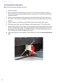
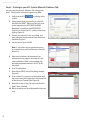
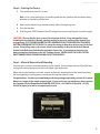
Assembling Your VersaLASER System
Assembling Your VLS System
Familiarize yourself with the instructions before getting started.
If you purchased the Computer Controlled Air Cleaner Cart, proceed to the Accessories section on the
CD for installation instructions. If you plan on placing the laser system on top of a table, continue with
the follwing steps.
CAUTION: Do not attempt to move or lift this system alone. Obtain assistance from two or three
additional people when lifting or carrying (secure motion system and doors before lifting). Bodily
injury may occur if improper lifting techniques are used or the system is dropped.
Unpacking the VLS
1. Unpack the laser system from its packaging.
2. With the assistance of one or two other people, pick up the VersaLASER and
place it on top of a table strong enough to support its weight (refer to the
specifications section on the CD).
3. Remove any paperwork placed on the top door.
4. Open the top door by lifting up on the handle.
15
Installation & Set-up Guide
5. Remove all materials inside of the laser system. You must do this before plugging in the
power cord otherwise, serious damage may occur.
6. Gently move the X-Axis arm (1) back and forth. It should slide freely.
7. Verify that all materials inside the VersaLASER have been removed.
8. Close the cover and continue to the next page.
16
Assembling Your VersaLASER System
Finalizing the Connections
Make the following connections in the order described, otherwise static electricity can potentially damage the computer and/or the laser systems electronics.
1. Connect the 3-inch (76.5 mm) flexible rubber exhaust system to the rear of the laser system if
you have not already done so.
2. Connect the laser system’s power cord and your computer’s power cord to a grounded
electrical outlet.
Note: International users may need to connect an adapter to the power cord to be able to plug
it into their power source.
CAUTION: Make sure that you attach the adapter correctly to the power cord and that your
power source is properly grounded (earthed).
3. Do not power on the laser system at this time.
Note: A properly installed 9-volt battery is necessary to operate the laser system. The laser
system will not function without a charged battery installed. Keep a spare 9-volt battery on
hand at all times.
4. Install the provided 9-volt Thermal Sensor battery into the back of the VLS laser system.
a. Gently push up on the Thermal Sensor battery holder drawer as indicated.
17
Installation & Set-up Guide
5. USB 2.0 Hi-Speed (Only)
The laser system comes equipped with a high quality, 6-foot (1.82 meters) USB 2.0 certified
cable. We recommend you use this provided cable.
CAUTION: Do not use any adapters, extension cables, USB cable longer than 6 feet (1.82
meters) or other devices between the computer’s USB port and the port on the laser system;
sporadic or unpredictable behavior may result.
a. Connect the USB cable provided between the USB port of the computer and the USB port
on the back of the VLS laser system. Do not use a USB cable longer than 6 feet (1.82 meters).
b. After connecting the USB cord, the “Found New Hardware Wizard” will open. Select “No, not
at this time.” Then click “Next” to continue.
18
Assembling Your VersaLASER System
c. Select “Install the software automatically.” Then Click “Next” to continue. You do not need to
insert the Software Installation CD-ROM.
d. A warning message will appear. Select “Continue Anyway.” Do not be concerned. Installing
the ULS Firmware will not harm your computer in any way. The firmware will begin to load.
e. Click “Finish” to close the Wizard.
f. Another set of New Hardware Wizard windows may appear after the initial USB connection.
Follow the same instructions as mentioned previously. Once completed, your new hardware is installed and ready to use.
g. Once installed, proceed to page 20.
19
Installation & Set-up Guide
Checking Beam Alignment
Note: You will not engrave anything at this time.
1. Open the top door.
2. Place a small piece of masking tape across the 3/4” (19 mm) hole in the focus carriage (1).
Gently rub the tape around the edge of the hole so that you can see the outline of the hole
through the tape (2).
3. Power on your computer and verify that the Universal Control Panel (UCP) icon is present on
the taskbar. If not, activate it by double-clicking on the “Universal Control Panel” icon on your
desktop.
4. Power on the laser system by pressing the Power button on the top of the VLS system.
5. With the top door open, a red dot will appear on the masking tape (3). The red dot should
appear centered, within 1/8 inch (3mm). If not, turn off the laser system, remove and re-install
the laser cartridge and try again. If the red dot still does not appear centered, please contact
our Customer Service Department at 480-609-0297 (USA), +43 1 402 22 50 (Austria), +81 (45)
224-2270 (Japan) or e-mail us at [email protected].
6. Laser beam alignment is now complete. Power off the laser system and remove the masking
tape.
Focus Carriage Beam Alignment
20
Running Your First Job
We will now illustrate how to use your laser system to engrave on a piece of anodized aluminum from
start to finish. In this example, you will raster engrave a Test Card on a 2 x 3.5 inch (50.8 x 89 mm), 0.0195
inch (0.49 mm) thick piece of anodized aluminum.
Note: For this example we will be using CorelDRAW X3 and the CorelDRAW sample file provided on the
software CD. Install CorelDRAW, but do not start a new project.
Step 1 – Loading and Positioning the Material
Open the top door and position the piece of anodized aluminum (1) into the upper left corner of the
table, against the rulers.
1
Step 2 – Creating the Graphic
Using CorelDRAW, open the sample graphic file found on the software installation CD that came with
the VLS system. The file is named ULSTest.cdr. The Software Installation CD contains test files in .cdr,
.eps, and .dxf.
21
Installation & Set-up Guide
Step 3 – Printing to your VLS System (Materials Database Tab)
You are using the Materials Database Tab in the printer
driver. Other graphic software programs may differ.
1. Verify that the UCP
taskbar.
is running in the
2. When you are ready to print the job, click FILE
and then click PRINT. Make sure that your laser
system appearsin the DESTINATION NAME
dropdown list, and then click PROPERTIES
(Figure 4) to display the VLS system printer driver
settings (Figure 5).
3. Choose your material, in this case metal, and
then select the correct material type: Aluminum
Anodized (Figure 5).
Figure 4
4. Set the Fixture Type to NONE.
Note: If you were using an optional accessory
or custom fixture, you would choose it from the
fixture list.
5. Measure the thickness of the material (we
recommend using calipers) and enter it in the
material thickness field. In the example, the
provided anodized aluminum is 0.019” (0.483
mm) thick.
6. Click OK when done.
Figure 5
7. Now click on PRINT in the Print dialog window
(Figure 4).
8. Click on the VLS system icon on the taskbar and
the current print job will appear in the Viewer Tab
of the Universal Control Panel (Figure 6).
9. Now click on the System Tab and verify that the
Auto Z box is checked.
10. Return to the Viewer Tab and proceed to the next
step.
Figure 6
22
Running Your First Job
Step 4 – Starting the Process
1. Turn on the exhaust and VLS system.
Note: Laser system cooling fans are variable speed and may speed up and slow down during
operation as needed to cool the lasers.
2. Make sure the material is positioned correctly within the engraving area.
3. Close the top door.
4. Click the green START button on the UCP to begin laser processing (Figure 6 on previous page).
CAUTION: Observe that the laser system is functioning as desired. If any abnormalities occur,
including, but not limited to, flaming, sparking, melting or excessive smoking of the material you
are engraving, stop the engraving process immediately by either pressing the pause
button or opening the top door. Re-check the settings in the printer driver as well as the laser
system. If everything seems to be correct, check focus manually as described in the User Manual
located in the Reference Guide booklet and adjust if necessary. If you cannot resolve the issue,
please contact your distributor or the ULS Customer Service. Never leave the laser system
unattended during the engraving or cutting process.
Step 5 – Material Removal and Reloading
Once the laser system has completed processing the material, the laser beam will turn off and the focus
carriage will move to the home position in the upper right hand corner.
Before opening the top door, wait a few seconds to allow any remaining fumes that are left over from
the laser engraving or cutting process to evacuate through the exhaust system.
Congratulations! You have just completed your first engraving project with your new VLS system.
Below is an image of the sample engraving job. If your results are not satisfactory, please contact
the Customer Service Department at 480-609-0297 (USA), +43 1 402 22 50 (Austria), +81 (45)
224-2270 (Japan) or e-mail us at [email protected].
23
Notes
Notes
©2008 Universal Systems, Inc. All Rights Reserved. The Universal Laser Systems logo and name, and VersaLASER are registered
trademarks, and High Power Density Focusing Optics, Quick Change, Rapid Reconfiguration, SuperSpeed are trademarks of
Universal Laser Systems, Inc. All other company and product names are trademarks or registered trademarks of their respective
companies.
Universal’s laser systems are protected under one or more of U.S. Patents: 5,051,558; 5,661,746; 5,754,575; 5,867,517; 5,881,087;
5,894,493; 5,901,167; 5,982,803; 6,181,719; 6,313,433; 6,342,687; 6,423,925; 6,424,670; 6,983,001; 7,060,934. Other U.S. and
international patents pending.
The VersaLASER system has been awarded U.S. Design Patent No. D517,474 for the unique design of its external cabinet, which
also functions as a Class 1 laser safety enclosure.
www.ulsinc.com
050-3251-00-A REV0409