1
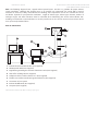
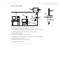
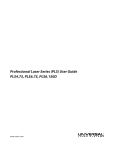
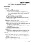
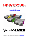
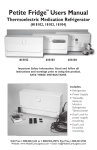
Universal Laser Systems
Professional Laser Series PLS3.75, PLS4.75, PLS6.75 and
PLS6.150D Installation and Setup Guide
Installation & Set-up Guide:
Professional Laser System PLS3.75, PLS4.75, PLS6.75
and PLS6.150D
Universal Laser Systems
Professional Laser Series PLS3.75, PLS4.75, PLS6.75 and
PLS6.150D Installation and Setup Guide
The Installation & Set-up Guide is designed to provide you with step-by-step instructions for proper installation and
set-up of your Universal laser system. Before getting started, you should become familiar with each section of the
Installation & Set-Up Guide: Proper Operating Environment Procedures, Software Installation and Requirements,
Assembling Your System and Running Your First Job.
Proper Operating Environment
This section will give you step-by-step instructions for site preparation and computer and software setup. Follow the
instructions in the order shown.
1. Establishing a Proper Operating Environment
2. Software Installation and Operating System Requirements
3. Assembling Your Professional Laser Series System
4. Running Your First Job
CAUTION: Damage to the PLS system due to inadequate or improper operating environment
is not covered under the Universal Laser Systems (ULS) Warranty. See the ULS Warranty for
additional information. The ULS Warranty can be found in your Reference Guide booklet. Should you require a copy of the Warranty, please contact your local Customer Service at
480-609-0297 (USA), +43 1 402 22 50 (Austria), +81 (45) 224-2270 (Japan) or e-mail us at support@
ulsinc.com.
Please refer to the Safety Manual before operating your laser system.
Environment (User Supplied)
1. The laser system must be installed in an office, laboratory, workshop or light duty manufacturing environment.
Dusty or dirty environments can damage the laser system. Keep the laser system isolated from any processes
that produce airborne particles such as sandblasting, sanding, machining, etc. Also, keep the PLS system isolated
from any equipment requiring mists of oil or water for lubrication. Airborne dust and liquids can coat and
damage optics and motion system components.
2. Avoid small, enclosed, non-ventilated areas. Some materials, after laser engraving or cutting, continue emitting
fumes for several minutes after processing. Having these materials present in a confined, unventilated room
can create a health hazard.
3. For best results, since the lasers are air-cooled, we recommend operating the laser system between the ambient
temperatures of 73ºF (22ºC) and 77ºF (25º C).
4. Avoid storing the laser system outside the temperatures of 50ºF (10ºC) and 95ºF (35º C) as excessively cold or
hot temperatures can damage the laser cartridge or reduce its lifetime.
5. Ambient humidity levels must be non-condensing to protect optics.
6. The laser system should be at least 3 feet (1 meter) away from any wall or obstruction.
Universal Laser Systems
Professional Laser Series PLS3.75, PLS4.75, PLS6.75 and
PLS6.150D Installation and Setup Guide
Electrical Power Source (User Supplied)
1. For your system’s electrical requirements, please refer to the “INPUT POWER” label near the power inlet.
2. CAUTION: Never remove the ground lead to the electrical cord and plug the PLS
system into a non-grounded outlet. A laser system that is not properly grounded is hazardous and has
the potential to cause severe or fatal electrical shock. Without proper grounding, the laser system may exhibit
sporadic or unpredictable behavior. Always plug the system into a properly grounded (earthed) outlet.
3. Noisy or unstable electricity and voltage spikes may cause interference and possible damage to the
electronics of the laser system. If electrical power fluctuations, brown outs or constant power outages are a
problem in your area, please contact your local Electrician to supply a power isolation and regulation module.
Electrically noisy equipment, such as equipment with large motors, can also cause interference if plugged into
the same outlet. It may be necessary to attach the laser system to a dedicated electrical line to resolve the
problem.
4. The laser system is designed as a Class I, Group A, pluggable device. It is also designed for connection to IT
power systems which provide the most flexibility to the user.
Exhaust System (User Supplied)
1. We recommend you consult with a licensed contractor to meet local safety and building code requirements.
2. The exhaust system must be capable of supplying a minimum of:
•
PLS3.75 and PLS4.75 - 250 CFM (cubic feet per minute) of airflow while under a load of 6 inches of static
pressure (425m3/hr at 1.5kPa)
•
PLS6.75 and PLS6.150D - 500 CFM (cubic feet per minute) of airflow while under a load of 6 inches of static
pressure (850m3/hr at 1.5kPa)
3. Do not install forward incline, backward incline, in-line or ventilator fans because these types of air handlers
are inadequate and inappropriate for this type of installation. A high-pressure blower must be used to meet
minimum airflow requirements.
4. For personal safety and noise control, we recommend that the exhaust blower be mounted outside the building.
5. Rigid tubing should be used for the majority of the connection between the blower and the laser system. The
tubing should be smooth-walled and have as few 90-degree bends as possible.
6. Install an exhaust gate to adjust airflow and to close off the exhaust when the laser is not in use. Place this gate
near the laser system within 5 to 10 feet (1.50 to 3.00 meters).
7. Use a short piece of industrial grade, wire-reinforced rubber tubing to connect the laser system’s exhaust
port to the exhaust gate and secure with a hose clamp. This will provide some mobility for your laser system
and will isolate exhaust blower vibrations from your laser system.
8. Wire the exhaust blower electrically to a wall switch in the same room for easy ON/OFF control.
Universal Laser Systems
Professional Laser Series PLS3.75, PLS4.75, PLS6.75 and
PLS6.150D Installation and Setup Guide
Note: The following diagram shows a typical exhaust system layout. Use this as a guideline for proper exhaust
system installation. Although this diagram serves as an example, we recommend you consult with a licensed
contractor to meet local safety, environmental and building code requirements and to also calculate the correct
size blower required for your particular installation. Length of exhaust pipe, exhaust pipe diameter, number of
90-degree angles and other restrictions must be calculated when determining the correct exhaust blower unit.
Installing an undersized or oversized blower is not only unsafe, but can also lead to excessive wear and tear to the
laser system and premature failure.
PLS3.75 and PLS4.75
2
1
9
8
4
7
3
5
6
1. Exhaust blower mounted outside* (User Supplied)
2. Weatherproof shield (User Supplied)
3. Rigid ducting matching the diameter of the blower inlet (User Supplied)
4. Shut-off or air-flow gate (User Supplied)
5. Adapter to the hose reduces from 4” to 3” (User Supplied)
6. Flexible, wire-reinforced, industrial grade rubber hose (User Supplied)
7. Connection to laser system
8. Exhaust On/Off switch (User Supplied)
9. Computer (User Supplied)
*Exhaust blower illustration my differ according to your region.
Universal Laser Systems
Professional Laser Series PLS3.75, PLS4.75, PLS6.75 and
PLS6.150D Installation and Setup Guide
PLS6.75 and PLS6.150D
2
3
1
10
5
9
4
4
3
6
6
5
7
6
8
7
8
Detail
1. Exhaust blower mounted outside* (User Supplied)
2. Weatherproof shield (User Supplied)
3. Rigid ducting matching the diameter of the blower inlet (User Supplied)
4. Adapter to the hose reduces from 4” to 3” (User Supplied)
5. Y-pipe (User Supplied)
6. Shut-off or air-flow gate(s) (User Supplied)
7. Flexible, wire-reinforced, industrial grade rubber hose (User Supplied)
8. Connection to laser system
9. Exhaust On/Off switch (User Supplied)
10. Computer (User Supplied)
*Exhaust blower illustration my differ according to your region.
Universal Laser Systems
Professional Laser Series PLS3.75, PLS4.75, PLS6.75 and
PLS6.150D Installation and Setup Guide
Software Installation and Requirements
Your computer is a critical component in the operation of the PLS system. In fact, you cannot operate the PLS system if
your computer is not connected, powered on, running Windows and running the Universal Control Panel (UCP) software.
You can only run one PLS system per computer at a time. You will need to purchase a separate computer for each
PLS system you own. The PLS system is not designed to be a network printer. You must operate the PLS system using
the computer that is directly attached to it via the provided 6-foot USB cable (2 meters). USB cables longer than 6 feet
(2 meters) may cause the PLS system to malfunction.
Computer and Operating System Requirements
Minimum Computer Requirements (User Supplied)
•
2.0 GHz processor (minimum)
•
Windows XP or Windows Vista*
•
1 GB of RAM (minimum); 2 GB of RAM (minimum) for Vista
operating systems
•
40 GB hard drive (15 GB free space) (minimum)
•
VGA monitor (minimum 1024 x 768 resolution)
•
CD-ROM drive/burner
•
Mouse and keyboard
•
Available USB 2.0 Hi-Speed compliant port only
•
Computer speakers (optional)
•
600 DPI scanner (optional)
•
Internet connection and e-mail address (optional)
*The PLS system is only compatible with a 32-bit Windows Operating
System. See www.microsoft.com for the minimum computer requirements to
run Windows Vista. The PLS system is not designed to run on the Macintosh
Operating System.
Note: Some computer manufacturers’ USB ports do not comply with USB 2.0 Hi-Speed standards. This may cause
the ILS system to exhibit erratic behavior. Confirm that your computer complies with USB 2.0 Hi-Speed by checking your
computer manual. For more information on USB 2.0 Hi-Speed compatibility, please visit www.usb.org.
Other USB peripheral devices that demand a large amount of computer processing power may slow down the
operation and productivity of the ILS system. If you experience problems with operation, we recommend you
disconnect other USB peripheral devices while the laser system is off. Do not connect or disconnet devices while
the laser system is running a job.
Universal Laser Systems
Professional Laser Series PLS3.75, PLS4.75, PLS6.75 and
PLS6.150D Installation and Setup Guide
Optimizing Windows
XP Performance
Windows XP, by default, displays many “visual
effects” that slow down the computer.
We
recommend that you turn off these effects by
right-clicking on the “My Computer” icon on your
desktop, then click “Properties” and then click the
“Advanced” tab. In the Performance section, click
“Settings,” then click “Adjust For Best Performance”
and then click “Apply.”
Vista Performance
Windows Vista, by default, displays many “visual
effects” that slow down the computer.
We
recommend that you turn off these effects by clicking
the “Start” button, right-clicking on “Computer,”
then
click “System Properties” and then click on
“Advanced System Settings” link. In the Performance
section, click “Settings,” then click “Adjust For Best
Performance” and then click “Apply.”
Computer Power Management
Power management is a configuration setting in Windows XP and Windows Vista that reduces the energy
consumption of computers and monitors by shutting them down after a period of inactivity. However, since your
computer is a critical component in the operation of the VLS system, you do not want your computer to go into
the Standby or Hibernate modes while your laser system is operating. Contact your IT Department if you need help
in configuring your computer.
XP
Vista
For the Power Scheme in use, select “Never” for all the
setting options: Turn off display and Put the computer to
sleep.
For the Power Scheme in use, select “Never” for all the
setting options: Turn off monitor, turn off hard disks,
system standby and system hibernates.
Universal Laser Systems
Professional Laser Series PLS3.75, PLS4.75, PLS6.75 and
PLS6.150D Installation and Setup Guide
Universal Control Panel (UCP) Installation CD-ROM
At this point you need to install the Windows XP/Vista Universal Control Panel (UCP) and printer driver. In order to
install the software, you need to have administrative privileges on the computer before starting installation. The Software
Installation CD-ROM can be found on the inside of this manual reference guide.
1. Insert the Software Installation CD-ROM into your PC’s CD drive. It should automatically launch the “Universal
Control Panel Installation” window. Select the laser series you are installing on the computer.
Note: If the setup window does not automatically launch, you can launch it manually. Locate your CD or
DVD drive using Windows Explorer and click on the Setup.exe application to launch the setup window.
2. Select the components you would like to install on your computer, then select the “Next” button.
Note: If you choose to only install the “Universal Control Panel,” you will need to proceed to step 4.
3. If you have selected to install the Printer Driver, you will then be prompted to select the laser system you
would like to install on the computer. Once selected, click the “Next” button.
Universal Laser Systems
Professional Laser Series PLS3.75, PLS4.75, PLS6.75 and
PLS6.150D Installation and Setup Guide
4. The installation process will proceed as indicated by a progress bar. Be patient. Loading the files can take a few
minutes depending on your computer’s processor speed.
5. When the installation process is finished, the “Completing the ULS Software Setup Wizard” window will
appear. Read the instructions and make your desired selection. If you Reboot Now, save all your work prior to
rebooting. If you decide to reboot later remember that you must reboot before connecting the PLS system to
your computer. Click on the “Finish” button to complete installation. The window will automatically close.
Remove the Software Installation CD-ROM. All the files required to operate your machine have been loaded
onto your computer.
Universal Laser Systems
Professional Laser Series PLS3.75, PLS4.75, PLS6.75 and
PLS6.150D Installation and Setup Guide
Assembling Your PLS System
Familiarize yourself with the instructions before getting started.
Depending on which PLS system you have purchased, assembly of your laser system may be required. Once the
system has been assembled, it is necessary to install the laser cartridge on the back of the machine and perform a
beam alignment check. Do not power up your laser system until the final step, “Checking Beam Alignment.”
CAUTION: Do not attempt to move or lift this system alone. Obtain assistance from three or four
additional people when lifting or carrying (secure motion system and doors before lifting). Bodily
injury may occur if improper lifting techniques are used or the system is dropped.
System Assembly - PLS3.75 and PLS4.75 system: Page 251
System Assembly - PLS6.75 and PLS6.150D system: Page 252
System Assembly - PLS3.75 and PLS4.75 System
Cart Assembly
1. Unpack the laser system from its packaging.
2. Remove the unassembled cart from the top of the laser system.
3. Assemble the cart as it appears in the diagram below, but leave all of the screws slightly loose, except for the
casters which should be tightened as far as possible into the cart leg.
5
9
8
3
5
1
9
7
2
9
2
9
5
4
5
3
7
6
1.
2.
3.
4.
5.
6.
7.
8.
7
6
9.
7
Back panel
Legs (both are identical)
Side panels (two)
Shelf panel
1/4-20 x ½, socket head screws
w/lock & flat washers (twelve)
Nuts (four)
Locking casters (four are identical)
10-32 x 3/8 socket head screws
w/lock & flat washers (two)
Connect to main enclosure
Universal Laser Systems
Professional Laser Series PLS3.75, PLS4.75, PLS6.75 and
PLS6.150D Installation and Setup Guide
4. With the assistance of three or four other people, place the system on top of the cart and
loosely install the provided screws that attach the machine to the cart. Be careful not to
pinch your fingers.
5. Open front door all the way to ensure that it does not come in contact with the cart legs. If the door should
come in contact with the cart legs, gently pull the cart legs apart to ensure there is non-contact between
the door and the cart legs. Securely tighten all the screws and re-check.
6. Attach your exhaust system’s wire-reinforced rubber tubing to the exhaust port at the rear of the laser
system and secure with a hose clamp.
7. Place the PLS system in the desired location for operation.
Proceed to page 255 “Laser Cartridge Installation.”
System Assembly - PLS6.75 and PLS6.150D System
1. Unpack the laser system from its packaging.
2. Place the laser system in the desired location for operation.
a. If a doorway is not wide enough to pass the laser system through, the system can be detached from the
cart stand and carried through the door on its side. To detach the system from the cart stand, proceed to the
steps below.
b. If you do not need to detach the laser system from the cart to move it to the desired location for operation,
you can proceed to “Laser Cartridge Installation” on page 255.
Detaching laser system from cart to fit through small doors (Optional)
1. Unplug the laser system from the electrical outlet.
2. At the back of the system, locate the four screws, remove them and the cover plate.
Universal Laser Systems
Professional Laser Series PLS3.75, PLS4.75, PLS6.75 and
PLS6.150D Installation and Setup Guide
3. Locate the three white connectors and the two black connectors. They are held in place by latches. Squeeze
on the sides in order to release the latches and unplug all five connectors.
4. Open the rear cover by placing your finger in the slotted hole and gently pull back on both sliding latches.
5. Fold the rear cover down to a resting position.
6. Locate the cavity (1) where the cables reside. Gently pull the cables upwards and rest them on top of the
sheet metal housing as the diagram below indicates.
Universal Laser Systems
Professional Laser Series PLS3.75, PLS4.75, PLS6.75 and
PLS6.150D Installation and Setup Guide
7. Gently close the rear cover.
8. Remove any packing materials or accessories from inside the laser system.
9. Using strong shipping tape or rope, tape the front door closed so that it does not open up when you tilt it.
10. Remove the eight screws that attach the cart stand to the laser system from the bottom (see below).
11. Lift the laser system straight up.
12. Place the laser system front door down on a dolly and roll it through the doorway. Lift and rotate the cart
to move it through the doorway.
13. Carefully line up the laser system and place it back on top of the cart stand. Be careful not to pinch your
fingers.
14. Reassemble the laser system and proceed to “Laser Cartridge Installation” on page 255.
Universal Laser Systems
Professional Laser Series PLS3.75, PLS4.75, PLS6.75 and
PLS6.150D Installation and Setup Guide
Laser Cartridge Installation
Note: The following images illustrate a PLS6.150D laser system with two laser cartridges. If you own a single laser
cartridge system, you will install the single laser cartridge only.
1. Make sure that your power cord to the system is not plugged in at this time. Place your finger in the slotted
hole and gently pull back on both sliding latches. Gently fold back the rear cover. Some laser systems are shipped
with keyed locks.
Note: Access latches for the laser cover are lockable. However, all systems are shipped from the factory with
latches unlocked. If you need to lock the latches, please contact our Customer Service Team at 480-609-0297
(USA), +43 1 402 22 50 (Austria), +81 (45) 224-2270 (Japan) or e-mail us at [email protected] for keys.
2. Visually locate the mounting blocks (1), the laser latch(es) (2) and alignment fork(s) (3). Notice that the alignment
fork has two plates, one small and one large. Locate the gap between the two plates.
Universal Laser Systems
Professional Laser Series PLS3.75, PLS4.75, PLS6.75 and
PLS6.150D Installation and Setup Guide
3. Observe the “V” groove along the upper (3) and lower (2) part of the laser cartridge base plate and the
alignment plate (1) at the end of the base plate.
4. If you have purchased two laser cartridges, mount the first cartridge onto the lower mounting blocks first. Single
laser users should mount the laser cartridge in the top position.
5. Pick up the laser cartridge by the ends and tilt it at a 30 degree angle as shown (1). Mount the cartridge onto
the mounting blocks shown in step 2 (page 255) by placing the upper “V” groove on top of the mounting
blocks. Slide the cartridge to the right until the outer edge (2) of the alignment plate contacts the inside edge
of the large plate of the alignment fork.
Universal Laser Systems
Professional Laser Series PLS3.75, PLS4.75, PLS6.75 and
PLS6.150D Installation and Setup Guide
6. Slowly rotate the laser cartridge, making sure that the alignment plate is centered in the gap in the alignment
fork. As you slowly release the weight of the laser, you should feel it lock itself smoothly into place. Never force
the laser into position. If the laser does not install smoothly, check for obstructions such as pinched wires or
hoses or a binding laser latch. Once installed, verify that the alignment plate is centered within the alignment
fork.
7. Plug in the power connector (1) to the corresponding laser cartridge. The power connector is labeled Top (2)
or Bottom (3). Single laser cartridge users should leave the bottom connector unplugged and out of the way.
8. Close the rear cover, making sure that wires or hoses do not become pinched when the cover is closed. Gently
close the rear cover until the sliding latches lock into place.
9. Once the laser cartridge has been installed, proceed to “Laser System Leveling” on page 258.
Universal Laser Systems
Professional Laser Series PLS3.75, PLS4.75, PLS6.75 and
PLS6.150D Installation and Setup Guide
Laser System Leveling
1. Place a bubble level (1) across the front (2) and rear cart legs (3). Adjust the caster height using the adjustment
screw (4) until both the rear part and the front part of the cart legs are level with respect to each other. Once
the system is level, secure all casters by tightening the nut (5) up against the cart leg.
2. Open the top door and remove the rubber band that is securing the arm in place.
3. Remove any remaining packing materials and accessories or any other items that may be located inside the
cabinet or on top of the engraving table.
3
5
4
1
2
4. Manually move the Focus Carriage by hand to the upper left corner.
Universal Laser Systems
Professional Laser Series PLS3.75, PLS4.75, PLS6.75 and
PLS6.150D Installation and Setup Guide
5. Place the focus tool* against the black lens plate (focus carriage) so that the flat edge of the focus tool rests
against the front side of the focus carriage as illustrated. Take note of the fit of the focus tool (it should look like
the diagram to the right) in the upper left corner of the system. This corner will be your reference point.
*Alternate leveling method available. See page 260.
6. Using the upper left corner as a reference point, move the focus carriage by hand to each corner and take
note of any differences between the fit of the focus tool in the upper left corner of the field and the fit of the
focus tool in each of the other corners.
Perfect Fit
Gap too big
Gap too big
Universal Laser Systems
Professional Laser Series PLS3.75, PLS4.75, PLS6.75 and
PLS6.150D Installation and Setup Guide
7. If one or more of the other corners does not match the upper left corner, adjust the caster directly underneath
that corner up or down until the focus tool fit at that corner matches the fit at the upper left corner. First loosen
the lock nut (1), then turn the adjusting screw (2) in 1/8 turns. Once the foot is at the correct height, tighten
the lock nut (1). When you are done, the focus tool fit at all four corners should be the same.
1
2
8. Once properly leveled, proceed to page 261.
*Alternate leveling method
For the best leveling results, use a digital caliper and adjust the caster directly under each corner that does not
match the height of the upper left corner until that corner matches the upper left corner’s height. Verify that you
zero out the caliper before taking any measurements. The height at each corner should be within 0.010” (0.254 mm)
of the height at the upper left corner.
Universal Laser Systems
Professional Laser Series PLS3.75, PLS4.75, PLS6.75 and
PLS6.150D Installation and Setup Guide
Finalizing the Connections
Make the following connections in the order described, otherwise static electricity can potentially damage the
computer and/or the laser systems electronics.
1. Connect the 3-inch (76.5 mm) flexible rubber exhaust system to the rear of the laser system if you have not
already done so.
2. Connect the laser system’s power cord and your computer’s power cord to a grounded electrical outlet.
Note: International users may need to connect an adapter to the power cord to be able to plug it into their power
source.
CAUTION: Make sure that you attach the adapter correctly to the power cord and that your
power source is properly grounded (earthed).
3. Do not power on the laser system at this time.
Note: A properly installed 9-volt battery is necessary to operate the laser system. The laser system will not
function without a charged battery installed. Keep a spare 9-volt battery on hand at all times.
4. Install the provided 9-volt Thermal Sensor battery into the PLS laser system. The Thermal Sensor battery
holder drawer is located on the side of the PLS6.150D near the power inlet and on the rear of the PLS6.75,
PLS4.75 and PLS3.75 laser systems.
a. Gently push up on the Thermal Sensor battery holder drawer as indicated. Pull the battery holder drawer
out.
b. Insert the 9-volt battery provided into the battery holder drawer.
c. Reinsert the battery holder drawer into the cavity until it latches in place.
Universal Laser Systems
Professional Laser Series PLS3.75, PLS4.75, PLS6.75 and
PLS6.150D Installation and Setup Guide
5. USB 2.0 Hi-Speed (Only)
The laser system comes equipped with a high quality, 6-foot (1.82 meters) USB 2.0 certified cable. We
recommend you use this provided cable.
CAUTION: Do not use any adapters, extension cables, USB cable longer than 6 feet (1.82
meters), or other devices between the computer’s USB port and the port on the laser system;
sporadic or unpredictable behavior may result.
a. Connect the USB cable provided between the USB port of the computer and the USB port on the back of the
PLS system. Do not use a USB cable longer than 6 feet (1.82 meters).
b. After connecting the USB cord, the “Found New Hardware Wizard” will open and offer to connect to
“Windows Update” to search for software. Select “No, not at this time.” Then click “Next” to continue.
Universal Laser Systems
Professional Laser Series PLS3.75, PLS4.75, PLS6.75 and
PLS6.150D Installation and Setup Guide
c. Select “Install the software automatically.” Then Click “Next” to continue. You do not need to insert the
Software Installation CD-ROM.
d. A warning message will appear. Select “Continue Anyway.” Do not be concerned. Installing the ULS
Firmware will not harm your computer in any way. The firmware will begin to load.
e. Click “Finish” to close the Wizard.
f. Another set of New Hardware Wizard windows may appear after the initial USB connection. Follow the
same instructions as mentioned previously. Once completed, your new hardware is installed and ready to
use.
g. Once installed, proceed to page 264.
Universal Laser Systems
Professional Laser Series PLS3.75, PLS4.75, PLS6.75 and
PLS6.150D Installation and Setup Guide
Checking Beam Alignment
Note: You will not engrave anything at this time.
1. Open the top door.
2. Place a small piece of masking tape across the 3/4” (19 mm) hole in the focus carriage (1). Gently rub the tape
around the edge of the hole so that you can see the outline of the hole through the tape (2).
3. Power on your computer and verify that the Universal Control Panel (UCP) icon is present on the taskbar. If not,
activate it by double-clicking on the “Universal Control Panel” icon on your desktop.
4. Power on the laser system by pressing the Power switch on the side of the PLS system.
5. With the top door open, a red dot will appear on the masking tape (3). The red dot should appear centered,
within 1/8 inch (3 mm). If not, turn off the laser system, remove and re-install the laser cartridge and try again.
If the red dot still does not appear centered, please contact our Customer Service Department at 480-609-0297
(USA), +43 1 402 22 50 (Austria), +81 (45) 224-2270 (Japan) or e-mail us at [email protected].
6. Laser beam alignment is now complete. Power off the laser system and remove the masking tape.
Focus Carriage Beam Alignment
Universal Laser Systems
Professional Laser Series PLS3.75, PLS4.75, PLS6.75 and
PLS6.150D Installation and Setup Guide
Running Your First Job
We will now illustrate how to use your laser system to engrave on a piece of anodized aluminum from start to finish.
In this example, you will raster engrave a Test Card on a 2 x 3.5 inch (50.8 x 89 mm), 0.0195 inch (0.49 mm) thick piece
of anodized aluminum.
Note: For this example we will be using CorelDRAW X3 and the CorelDRAW sample file provided on the software
CD. Install CorelDRAW, but do not start a new project.
Step 1 – Loading and Positioning the Material
Open the top door and position the piece of anodized aluminum (1) into the upper left corner of the table, against the
rulers.
1
Step 2 – Creating the Graphic
Using CorelDRAW, open the sample graphic file found on the software installation CD that came with the PLS
system. The file is named ULSTest.cdr. The Software Installation CD contains test files in .cdr, .eps, and .dxf.
Universal Laser Systems
Professional Laser Series PLS3.75, PLS4.75, PLS6.75 and
PLS6.150D Installation and Setup Guide
Step 3 – Printing to your PLS System (Materials Database Tab)
You are using the Materials Database Tab in the printer driver. Other graphic software programs may differ.
1. Verify that the UCP
is running in the taskbar.
2. When you are ready to print the job, click FILE and then
click PRINT. Make sure that your laser system appears
in the DESTINATION NAME dropdown list, and then
click PROPERTIES (Figure 4) to display the PLS system
printer driver settings (Figure 5).
3. Choose your material, in this case metal, and then select
the correct material type: Aluminum Anodized (Figure
5).
4. Set the Fixture Type to NONE.
Figure 4
Note: If you were using an optional accessory or
custom fixture, you would choose it from the fixture list.
5. Measure the thickness of the material (we recommend
using calipers) and enter it in the material thickness
field. In the example, the provided anodized aluminum
is 0.019” (0.483 mm) thick.
6. Click OK when done.
7. Now click on PRINT in the Print dialog window (Figure
4).
8. Click on the PLS system icon on the taskbar and the
current print job will appear in the Viewer Tab of the
Universal Control Panel (Figure 6).
Figure 5
9. Now click on the System Tab and verify that the Auto Z
box is checked.
10. Return to the Viewer Tab and proceed to the next step.
Figure 6
Universal Laser Systems
Professional Laser Series PLS3.75, PLS4.75, PLS6.75 and
PLS6.150D Installation and Setup Guide
Step 4 – Starting the Process
1. Turn on the exhaust and PLS system.
Note: Laser system cooling fans are variable speed and may speed up and slow down during operation as
needed to cool the lasers.
2. Make sure the material is positioned correctly within the engraving area.
3. Close the top door.
4. Click the green START button on the UCP to begin laser processing (Figure 6 on previous page).
CAUTION: Observe that the laser system is functioning as desired. If any abnormalities
occur, including, but not limited to, flaming, sparking, melting or excessive smoking of the
material you are engraving, stop the engraving process immediately by either pressing
the pause button or opening the top door. Re-check the settings in the printer driver as
well as the laser system. If everything seems to be correct, check focus manually as described
in the User Manual located in the Reference Guide booklet and adjust if necessary. If you
cannot resolve the issue, please contact your distributor or the ULS Customer Service. Never
leave the laser system unattended during the engraving or cutting process.
Step 5 – Material Removal and Reloading
Once the laser system has completed processing the material, the laser beam will turn off and the focus carriage
will move to the home position in the upper right hand corner.
Before opening the top door, wait a few seconds to allow any remaining fumes that are leftover from the laser
engraving or cutting process to evacuate through the exhaust system.
Congratulations! You have just completed your first engraving project with your new PLS system. Below is an
image of the sample engraving job. If your results are not satisfactory, please contact the Customer Service
Department at 480-609-0297 (USA), +43 1 402 22 50 (Austria), +81 (45) 224-2270 (Japan) or e-mail us at support@
ulsinc.com.