1
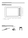
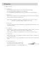
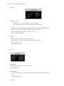
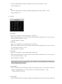
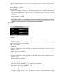
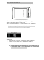
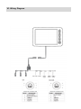
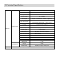
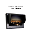
USER’s GUIDE MANUAL 5” Digital TFT LCD Monitor Model : MTB5300D I.I.Contents / Warning Contents / Warning I. Contents / Warning --------------------------------------------------- 1 II. Front Feature / Accessory ---------------------------------------------------- 2 III. Operation ---------------------------------------------------- 3–5 IV. Wiring Connection ----------------------------------------------------- 6 V. Technical Specification ----------------------------------------------------- 7 WARNING RISK OF ELECTRIC SHOCK DO NOT OPEN To reduce the risk of electric shock, do not remove the cover (or back). No user serviceable part inside. Refer servicing to qualified service personnel. The lightning flash with arrowhead symbol, within an equilateral triangle, is intended to alert the user to the presence of un-insulated “dangerous voltage” within the product’s enclosure that may be of sufficient magnitude to constitute a risk of electric shock to persons. This exclamation point within an equilateral triangle is intended to alert the user to the presence of important operating and maintenance (servicing) instructions in the literature accompanying the appliance. Design and Specification are subject to change without notice. II. Front Feature & Accessory ◈ Front Feature ① SCAN (UP) ⑦ ② CA. SEL (DOWN) ③ MENU ④ Dimmer ⑤ VOLUME DOWN VOLUME UP ⑧ POWER ◈ Accessory Camera Input Cable Fan Type Stand User’s Guide III. Operation 1. Menu Control Key 1) Power Key • The Power LED indicates the RED Color at the Power OFF (Stand-By Mode). • The Power LED indicates the GREEN Color at the Power ON. • The LAST MEMORIZED CHANNEL displays when the POWER turns ON (Factory Default). 2) Menu Key • When pressing the MENU Key during POWER ON Mode, the OSD appears and the selected letters on OSD are classified in a different color. • When pressing the MENU Key repeatedly in OSD Mode, the monitor displays in order as ; FUNCTION → PICTURE→CAMERA→CAMERA→Clear of OSD. 3) Dimmer Key • The Monitor Brightness is manually adjustable by pressing “DIM” button depending on the surrounding condition. 4) △ SCAN Key • When pressing △ SCAN Key on displaying image, displays “Camera 1 image -> Camera 2 image -> Camera image 3” repeatedly until pressing △ SCAN Key again. • When pressing △ SCAN Key on the MENU, the cursor moves up for selecting an option. 5) CA. SEL▽ Key • When pressing CA. SEL ▽ key repeatedly on displaying image, the display is changed CA1 -> CA2 -> CA3 in order. • When pressing CA. SEL ▽ Key on the MENU, the cursor moves down for selecting an option. 6) Volume Up/Down Key • To increase the Volume, press “+ Volume” Key. • To decrease the Volume, press “Volume – “Key. • Adjustable Volume Range : 0 - 100 (Factory Default : 50) 2. How to set up the MENU Function 1) Function • POWER ON/OFF - ON: When ACC is On, the display is On automatically. - OFF: The display is On by pressing power button manually. • Language : 6 Language (ENGLISH/GERMAN/FRENCH/ITALIAN/SPANISH/DUTCH) - Locate the cursor at Language by SCAN and/or CA.SEL key. - Select the desired language by Volume -/+ key. - Factory default: ENGLISH. • RESET All set values are initialized to factory defaults. - Locate the cursor on the RESET by SCAN and/or CA.SEL key. - Select Volume + key. - The monitor turns off. 2) Picture • CONTRAST - Adjust the Contrast by the Volume -/+ Key. *Factory Default: 50 • BRIGHTNESS - Press the SCAN and/or the CA.SEL Key, adjust the Brightness by the Volume -/+ Keys. *Factory Default: 50 • COLOR – Press the SCAN and/or CA.SEL Key, adjust the Color by the Volume -/+ Key. *Factory Default: 50 • TINT – Press the SCAN and/or CA.SEL Key, adjust the Brightness by the Volume -/+ Key. *Factory Default: 50 3) Camera • CA1 SCAN - Move to the camera 1 by the SCAN and/or CA.SEL Key. - Adjust the displaying time of the camera 1 while scanning camera and it is set up from 0 to 9 seconds by Volume -/+ Key. * Factory Default: 3 second. • CA2 SCAN - Move to the camera 2 by the SCAN and/or CA.SEL Key. - Adjust the displaying time of the camera 2 while scanning camera and it is set up from 0 to 9 seconds by Volume -/+ Key. * Factory Default: 3 seconds • CA3 SCAN – Move to the camera 3 by the SCAN and/or CA.SEL Key. - Adjust the displaying time of the camera 3 while scanning camera and it is set up from 0 to 9 seconds by Volume -/+ Key. * Factory Default: 3 seconds *If the value is set at “0”, the image of the camera is not displayed while scanning the channels (Skipping the channel). • CA1 TRIGGER - Press the SCAN and/or CA.SEL Key, adjust the displaying time of the camera 1 after the trigger is disengaged and it is set up from 0 to 9 seconds by Volume -/+ Key .* Factory Default: 3 seconds • CA2 TRIGGER – Press the SCAN and/or CA.SEL Key, adjust the displaying time of the camera 2 after the trigger is disengaged and it is set up from 0 to 9 seconds from 0 to 9 seconds by Volume /+ Keys. *Factory Default : 3 seconds • CA3 TRIGGER – Press the SCAN and/or CA.SEL Key, adjust the displaying time of the camera 3 after the trigger is disengaged and it is set up from 0 to 9 seconds from 0 to 9 seconds by Volume -/+ Keys. *Factory Default : 3 seconds *If the value is set at “0”, the display is promptly changed to the image of the camera displaying prior to the trigger on after the trigger is disengaged. 4) Camera • CAMERA 1 – Press the SCAN and/or CA.SEL Key, select the Normal or Mirror Image of Camera 1 by the Volume -/+ Key. - NOR : Normal Image (Factory Default) MIR : Mirror Image • CAMERA 2 – Press the SCAN and/or CA.SEL Key, select the Normal or Mirror Image of Camera 2 by the Volume -/+ Key. – Normal Image (Factory Default) • CAMERA 3 – Press the SCAN and/or CA.SEL Key, select the Normal or Mirror Image of Camera 3 by the Volume -/+ Key. – Normal Image (Factory Default) • Adjustable Guide Line (Parking Guide Line) - Locate the cursor at DISTANCE by the SCAN and/or CA.SEL Key. - Select ON or OFF by the VOLUME -/+ Key. - ON : Displayed the Adjustable Guide Line (Factory Default) - OFF : No displayed the Guide Line. – When the Camera 1 turns “ON” by the Trigger (“R” gear) in the Standby Mode, displays the Guide Line for the adjustment. *How to adjust the Parking Guide Line User can adjust the Guide Line in accordance with the Vehicle’s Width as follows. • The Guide Line (Parking Line) is displayed when the trigger signal is engaged. • Select the Left or Right Line by the SCAN/CA.SEL key. • Adjust the Guide Line (Parking Line) to the left or the Right by the – VOLUME+ key. * To adjust the parking guide line, the DISTANCE should be “ON” in OSD Setting. The adjustment is only applicable while the trigger is engaged. 5) Camera • SCAN MODUS - Move to the option screen of the SCAN MODUS by pressing the MENU key. - Locate the cursor at a desired camera by the SCAN and/or CA.SEL Key. - Select ON or OFF by the Volume -/+ Key. The camera set at “ON” is not scanned when a user tries to scan all cameras one by one by pressing “CA.SEL ▽” key. It is useful to select “OFF” for those camera channels which are not connected with a camera. VI. Wiring Diagram VI. Technical Specification Display Panel 5” Digital TFT LCD Panel Resolution 640 x RGB x 480 pixels Brightness 250cd/㎡ Screen mode 4 : 3 Screen View Angle Top:50° Bottom:70° Left:70° Automatic Screen On Rear View Image Specification Monitor via Reversing gear signal or Auto power Housing Aluminum Die-casting Display Mode Normal/Mirror Image with Adjustable Guide Line Camera Input 3 (4-pin mini DIN) Audio Input Power Source A Power Consumption Operating Temp. Dimensions Accessory Right:70° 3 (1V-P.P, 8Ω) DC 12V – 30V (Free Voltage) Max. 650mA -20℃ - +70℃ (-4℉ - 158℉) Storage Temp. -30℃ - +85℃ ( -22℉ - 185℉) Audio Output Built-in Speaker(1W) Waterproof IP 68 Weight 450g Dimensions 105(W) x 152(H) X 23(D) mm Stand Bracket, Camera Input Cable, Manual