1
Guardmaster MSR57P Speed
Monitoring Safety Relay
User Manual
(Catalog Number
440R-S845AER-NNL)
Important User Information
Solid state equipment has operational characteristics differing from those of electromechanical equipment. Safety
Guidelines for the Application, Installation and Maintenance of Solid State Controls (publication SGI-1.1 available
from your local Rockwell Automation sales office or online at http://literature.rockwellautomation.com) describes
some important differences between solid state equipment and hard-wired electromechanical devices. Because of
this difference, and also because of the wide variety of uses for solid state equipment, all persons responsible for
applying this equipment must satisfy themselves that each intended application of this equipment is acceptable.
In no event will Rockwell Automation, Inc. be responsible or liable for indirect or consequential damages resulting
from the use or application of this equipment.
The examples and diagrams in this manual are included solely for illustrative purposes. Because of the many
variables and requirements associated with any particular installation, Rockwell Automation, Inc. cannot assume
responsibility or liability for actual use based on the examples and diagrams.
No patent liability is assumed by Rockwell Automation, Inc. with respect to use of information, circuits, equipment,
or software described in this manual.
Reproduction of the contents of this manual, in whole or in part, without written permission of Rockwell
Automation, Inc., is prohibited.
Throughout this manual, when necessary, we use notes to make you aware of safety considerations.
WARNING
IMPORTANT
ATTENTION
Identifies information about practices or circumstances that can cause an explosion in a
hazardous environment, which may lead to personal injury or death, property damage, or
economic loss.
Identifies information that is critical for successful application and understanding of the product.
Identifies information about practices or circumstances that can lead to personal injury or death,
property damage, or economic loss. Attentions help you identify a hazard, avoid a hazard, and
recognize the consequence
SHOCK HAZARD
Labels may be on or inside the equipment, for example, a drive or motor, to alert people that
dangerous voltage may be present.
BURN HAZARD
Labels may be on or inside the equipment, for example, a drive or motor, to alert people that
surfaces may reach dangerous temperatures.
Rockwell Automation, Allen-Bradley, TechConnect, Guardmaster, Kinetix, PowerFlex, SCANport, RSLinx, DriveExplorer, and DriveExecutive are trademarks of Rockwell Automation, Inc.
Trademarks not belonging to Rockwell Automation are property of their respective companies.
Table of Contents
Preface
About This Publication . . . . .
Who Should Use This Manual
Conventions . . . . . . . . . . . . .
Terminology . . . . . . . . . . . . .
Additional Resources. . . . . . .
.
.
.
.
.
.
.
.
.
.
.
.
.
.
.
.
.
.
.
.
.
.
.
.
.
.
.
.
.
.
.
.
.
.
.
.
.
.
.
.
.
.
.
.
.
.
.
.
.
.
.
.
.
.
.
.
.
.
.
.
.
.
.
.
.
.
.
.
.
.
.
.
.
.
.
.
.
.
.
.
.
.
.
.
.
.
.
.
.
.
.
.
.
.
.
.
.
.
.
.
.
.
.
.
.
.
.
.
.
.
.
.
.
.
.
. 9
. 9
. 9
. 9
11
Introduction . . . . . . . . . . . . . . . . . . . . . . . . . . . . . . . .
Safety Certification . . . . . . . . . . . . . . . . . . . . . . . . . . .
Important Safety Considerations . . . . . . . . . . . . . . .
Safety Category 4 Performance Definition . . . . . . . .
Stop Category Definitions. . . . . . . . . . . . . . . . . . . .
Performance Level and Safety Integrity Level (SIL) 3
Functional Proof Tests. . . . . . . . . . . . . . . . . . . . . . . . .
PFD and PFH Definitions . . . . . . . . . . . . . . . . . . . . . .
PFD and PFH Data . . . . . . . . . . . . . . . . . . . . . . . . . . .
Safe State . . . . . . . . . . . . . . . . . . . . . . . . . . . . . . . . . .
Safety Reaction Time. . . . . . . . . . . . . . . . . . . . . . . . . .
Considerations for Safety Ratings . . . . . . . . . . . . . . . . .
Output Pulse Test Considerations . . . . . . . . . . . . . .
Considerations for Single-encoder Applications . . . .
Contact Information if Device Failure Occurs . . . . . . . .
.
.
.
.
.
.
.
.
.
.
.
.
.
.
.
.
.
.
.
.
.
.
.
.
.
.
.
.
.
.
..
..
..
..
..
..
..
..
..
..
..
..
..
..
..
13
13
14
15
15
16
16
16
17
17
18
18
19
19
22
Introduction . . . . . . . . . . . . . . . . . . . . . . . . . . . . . . . . . . . .
Safety Functions . . . . . . . . . . . . . . . . . . . . . . . . . . . . . . . . .
Safety Modes . . . . . . . . . . . . . . . . . . . . . . . . . . . . . . . . .
Disabled Mode . . . . . . . . . . . . . . . . . . . . . . . . . . . . . . .
Lock Monitoring . . . . . . . . . . . . . . . . . . . . . . . . . . . . . .
Safe Maximum Speed, Safe Maximum Acceleration, and
Safe Direction Monitoring. . . . . . . . . . . . . . . . . . . . . . . .
Hardware Features . . . . . . . . . . . . . . . . . . . . . . . . . . . . . . .
Configuration . . . . . . . . . . . . . . . . . . . . . . . . . . . . . . . . . . .
23
23
24
24
25
Chapter 1
Safety Concept
Chapter 2
About the MSR57P Speed
Monitoring Safety Relay
25
26
27
Chapter 3
Installation and Wiring
3Publication 440R-UM004A-EN-P - December 2008
Introduction . . . . . . . . . . . . . . . . .
General Safety Information . . . . . .
Environment and Enclosure. . . . . .
Considerations for Reducing Noise.
Dimensions. . . . . . . . . . . . . . . . . .
Spacing Requirements . . . . . . . . . .
Mount the MSR57P Relay. . . . . . . .
Power Supply Requirements . . . . .
Removable Terminal Blocks . . . . .
.
.
.
.
.
.
.
.
.
.
.
.
.
.
.
.
.
.
.
.
.
.
.
.
.
.
.
.
.
.
.
.
.
.
.
.
.
.
.
.
.
.
.
.
.
.
.
.
.
.
.
.
.
.
.
.
.
.
.
.
.
.
.
.
.
.
.
.
.
.
.
.
.
.
.
.
.
.
.
.
.
.
.
.
.
.
.
.
.
.
.
.
.
.
.
.
.
.
.
.
.
.
.
.
.
.
.
.
.
.
.
.
.
.
.
.
.
.
.
.
.
.
.
.
.
.
.
.
.
.
.
.
.
.
.
.
.
.
.
.
.
.
.
.
.
.
.
.
.
.
.
.
.
.
.
.
.
.
.
.
.
.
.
.
.
.
.
.
.
.
.
29
30
31
31
31
32
32
32
33
3
Table of Contents
Circuit Diagram. . . . . . . . . . . . . . . . . . . . . . . . . . . . .
Terminal Connections . . . . . . . . . . . . . . . . . . . . . . . .
Compatible Encoders . . . . . . . . . . . . . . . . . . . . . . . .
Connect an Encoder . . . . . . . . . . . . . . . . . . . . . . . . .
Encoder Cable Specifications . . . . . . . . . . . . . . . . . . .
Feedback Cable Connections for Kinetix 2000, Kinetix
Kinetix 7000 and Ultra3000 Drives . . . . . . . . . . . . . . .
Flying-lead Feedback Cable Pin-outs. . . . . . . . . . .
Wiring Low-profile Connector Kits . . . . . . . . . . . .
Feedback Connections for PowerFlex 70 Drives . . . . .
Safe Off Board Terminal Block
(Enhanced Control Only) . . . . . . . . . . . . . . . . . . .
Encoder Interface Terminal Block
(Enhanced Control Only) . . . . . . . . . . . . . . . . . . .
Feedback Connections for PowerFlex 700S Drives . . .
Connect a Configuration Device . . . . . . . . . . . . . . . .
.....
.....
.....
.....
.....
6000,
.....
.....
.....
.....
33
34
35
36
42
42
44
51
52
. . . . . 53
. . . . . 53
. . . . . 55
. . . . . 55
Chapter 4
Speed Monitoring I/O Signals
Introduction . . . . . . . . . . . . . . . . . . . . . . . .
Inputs. . . . . . . . . . . . . . . . . . . . . . . . . . . . .
Safe Stop Input (SS_In) . . . . . . . . . . . . .
Safe Limited Speed Input (SLS_In) . . . . .
Door Monitor Input (DM_In) . . . . . . . . .
Enabling Switch Monitor Input (ESM_In).
Lock Monitor Input (LM_In) . . . . . . . . . .
Reset Input (Reset_In) . . . . . . . . . . . . . .
Reset Loop Input (RL_In) . . . . . . . . . . . .
Outputs . . . . . . . . . . . . . . . . . . . . . . . . . . .
Safety Control Outputs . . . . . . . . . . . . . .
Diagnostic Outputs . . . . . . . . . . . . . . . .
.
.
.
.
.
.
.
.
.
.
.
.
.
.
.
.
.
.
.
.
.
.
.
.
.
.
.
.
.
.
.
.
.
.
.
.
.
.
.
.
.
.
.
.
.
.
.
.
.
.
.
.
.
.
.
.
.
.
.
.
.
.
.
.
.
.
.
.
.
.
.
.
.
.
.
.
.
.
.
.
.
.
.
.
.
.
.
.
.
.
.
.
.
.
.
.
.
.
.
.
.
.
.
.
.
.
.
.
.
.
.
.
.
.
.
.
.
.
.
.
.
.
.
.
.
.
.
.
.
.
.
.
.
.
.
.
.
.
.
.
.
.
.
.
57
57
60
60
60
61
61
62
63
63
63
70
Introduction . . . . . . . . . . . . . . . . . . . . . . . . . . . .
Cascaded Configuration. . . . . . . . . . . . . . . . . . . .
Safety Mode . . . . . . . . . . . . . . . . . . . . . . . . . . . .
Reset Type . . . . . . . . . . . . . . . . . . . . . . . . . . . . .
Reset Qualification . . . . . . . . . . . . . . . . . . . . . . .
Overspeed Response Time . . . . . . . . . . . . . . . . .
Speed Resolution Accuracy for Rotary Systems
Speed Resolution Accuracy for Linear Systems
Language Code . . . . . . . . . . . . . . . . . . . . . . . . . .
Max Display Speed . . . . . . . . . . . . . . . . . . . . . . .
General Parameter List . . . . . . . . . . . . . . . . . . . .
Feedback Monitoring . . . . . . . . . . . . . . . . . . . . .
Feedback Polarity . . . . . . . . . . . . . . . . . . . . .
.
.
.
.
.
.
.
.
.
.
.
.
.
.
.
.
.
.
.
.
.
.
.
.
.
.
.
.
.
.
.
.
.
.
.
.
.
.
.
.
.
.
.
.
.
.
.
.
.
.
.
.
.
.
.
.
.
.
.
.
.
.
.
.
.
.
.
.
.
.
.
.
.
.
.
.
.
.
..
..
..
..
..
..
..
..
..
..
..
..
..
73
73
74
74
75
75
76
78
79
80
80
81
82
Chapter 5
General Relay and Feedback
Monitoring Configuration
4
Publication 440R-UM004A-EN-P - December 2008
Table of Contents
Single Encoder. . . . . . . . .
Dual Encoders . . . . . . . . .
Feedback Voltage Monitor
Feedback Fault . . . . . . . .
Feedback Parameter List . . . .
......
......
Range .
......
......
.
.
.
.
.
.
.
.
.
.
.
.
.
.
.
.
.
.
.
.
.
.
.
.
.
.
.
.
.
.
.
.
.
.
.
.
.
.
.
.
.
.
.
.
.
.
.
.
.
.
.
.
.
.
.
.
.
.
.
.
.
.
.
.
.
.
.
.
.
.
.
.
.
.
.
.
.
.
.
.
.
.
.
.
.
82
82
85
86
86
Chapter 6
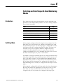
Safe Stop and Safe Stop with Door Introduction . . . . . . . . . . . . . . . . . . . . . . . . . . . . . . . . . . . . 89
Safe Stop Mode. . . . . . . . . . . . . . . . . . . . . . . . . . . . . . . . . . 89
Monitoring Modes
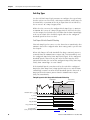
Safe Stop Types . . . . . . . . . . . . . . . . . . . . . .
Standstill Speed and Position Tolerance . . . .
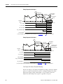
Deceleration Monitoring. . . . . . . . . . . . . . . .
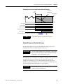
Safe Stop Reset . . . . . . . . . . . . . . . . . . . . . .
Door Control . . . . . . . . . . . . . . . . . . . . . . . .
Lock Monitoring . . . . . . . . . . . . . . . . . . . . .
Safe Stop Parameter List . . . . . . . . . . . . . . . . . .
Safe Stop Wiring Example . . . . . . . . . . . . . . . . .
Safe Stop with Door Monitoring Mode . . . . . . . .
Lock Monitoring . . . . . . . . . . . . . . . . . . . . .
SS Reset. . . . . . . . . . . . . . . . . . . . . . . . . . . .
Safe Stop with Door Monitoring Parameter List. .
Safe Stop with Door Monitoring Wiring Example
.
.
.
.
.
.
.
.
.
.
.
.
.
.
.
.
.
.
.
.
.
.
.
.
.
.
.
.
.
.
.
.
.
.
.
.
.
.
.
.
.
.
.
.
.
.
.
.
.
.
.
.
.
.
.
.
.
.
.
.
.
.
.
.
.
.
.
.
.
.
.
.
.
.
.
.
.
.
.
.
.
.
.
.
.
.
.
.
.
.
.
.
.
.
.
.
.
.
.
.
.
.
.
.
.
.
.
.
.
.
.
90
93
94
95
97
99
99
102
102
103
103
103
104
Chapter 7
Safe Limited Speed (SLS) Modes
Publication 440R-UM004A-EN-P - December 2008
Introduction . . . . . . . . . . . . . . . . . . . . . . . . . . . . . . . . . . .
Safe Limited Speed (SLS) Mode . . . . . . . . . . . . . . . . . . . . .
Safe Limited Speed Reset . . . . . . . . . . . . . . . . . . . . . . .
Safe Limited Speed Parameter List . . . . . . . . . . . . . . . . . . .
Safe Limited Speed Wiring Example. . . . . . . . . . . . . . . . . .
Safe Limited Speed with Door Monitoring Mode. . . . . . . . .
Safe Limited Speed Reset . . . . . . . . . . . . . . . . . . . . . . .
SLS with Door Monitoring Parameter List . . . . . . . . . . . . . .
SLS with Door Monitoring Wiring Example. . . . . . . . . . . . .
Safe Limited Speed with Enabling Switch Monitoring Mode.
Safe Stop Reset (SS Reset) and Safe Limited Speed Reset
(SLS Reset) . . . . . . . . . . . . . . . . . . . . . . . . . . . . . . . . .
SLS with Enabling Switch Monitoring Parameter List . . . . . .
SLS with Enabling Switch Monitoring Wiring Example . . . .
Safe Limited Speed with Door Monitoring and Enabling
Switch Monitoring Mode . . . . . . . . . . . . . . . . . . . . . . . . . .
Behavior During SLS Monitoring. . . . . . . . . . . . . . . . . .
Behavior While SLS Monitoring is Inactive . . . . . . . . . .
Behavior During SLS Monitoring Delay . . . . . . . . . . . . .
Safe Stop Reset (SS Reset) and Safe Limited Speed Reset
(SLS Reset) . . . . . . . . . . . . . . . . . . . . . . . . . . . . . . . . .
105
105
107
108
109
110
111
111
112
112
113
114
115
115
117
117
117
118
5
Table of Contents
SLS with Door Monitoring and Enabling Switch Monitoring
Parameter List . . . . . . . . . . . . . . . . . . . . . . . . . . . . . . . . . .
SLS with Door Monitoring and Enabling Switch Monitoring
Wiring Example . . . . . . . . . . . . . . . . . . . . . . . . . . . . . . . .
Safe Limited Speed Status Only Mode . . . . . . . . . . . . . . . .
Speed Hysteresis . . . . . . . . . . . . . . . . . . . . . . . . . . . . .
SLS Status Only Parameter List . . . . . . . . . . . . . . . . . . . . . .
SLS Status Only Wiring Examples. . . . . . . . . . . . . . . . . . . .
118
119
119
120
121
122
Chapter 8
Slave Modes for Multi-axis
Cascaded Systems
Introduction . . . . . . . . . . . . . . . . . . . . . . . . . . . . . . . .
Cascaded Configurations . . . . . . . . . . . . . . . . . . . . . . .
Slave, Safe Stop Mode . . . . . . . . . . . . . . . . . . . . . . . . .
Slave, Safe Stop Parameter List. . . . . . . . . . . . . . . . . . .
Slave, Safe Stop Wiring Examples . . . . . . . . . . . . . . . .
Slave, Safe Limited Speed Mode. . . . . . . . . . . . . . . . . .
Slave, Safe Limited Speed Parameters. . . . . . . . . . . . . .
Slave, Safe Limited Speed Wiring Examples . . . . . . . . .
Slave, Safe Limited Speed Status Only Mode. . . . . . . . .
Slave, Safe Limited Speed Status Only Parameter List . .
Slave, Safe Limited Speed Status Only Wiring Examples
Multi-axis Connections . . . . . . . . . . . . . . . . . . . . . . . .
Cascaded System Examples . . . . . . . . . . . . . . . . . . . . .
.
.
.
.
.
.
.
.
.
.
.
.
.
.
.
.
.
.
.
.
.
.
.
.
.
.
.
.
.
.
.
.
.
.
.
.
.
.
.
125
125
127
127
129
132
132
133
135
135
135
137
139
.
.
.
.
.
.
.
.
.
.
.
.
145
145
148
150
Chapter 9
Safe Maximum Speed and
Direction Monitoring
Introduction . . . . . . . . . . . . . . . . . . . . . . . . . . . .
Safe Maximum Speed (SMS) Monitoring . . . . . . . .
Safe Maximum Acceleration (SMA) Monitoring . . .
Safe Direction Monitoring (SDM) . . . . . . . . . . . . .
Max Speed, Max Accel, and Direction Monitoring
Parameter List . . . . . . . . . . . . . . . . . . . . . . . . . . .
.
.
.
.
.
.
.
.
.
.
.
.
.
.
.
.
. . . . . . . 151
Chapter 10
Safety Configuration and
Verification
6
Introduction . . . . . . . . . . . . . . . . . . . . . . . . . . .
Safety Configuration . . . . . . . . . . . . . . . . . . . . .
Configuration Signature ID . . . . . . . . . . . . . .
Safety-lock. . . . . . . . . . . . . . . . . . . . . . . . . .
Set a Password. . . . . . . . . . . . . . . . . . . . . . .
Reset the Password . . . . . . . . . . . . . . . . . . .
Reset the Relay . . . . . . . . . . . . . . . . . . . . . .
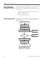
Basics of Application Development and Testing .
Commissioning the System . . . . . . . . . . . . . . . .
Specify the Safety Configuration . . . . . . . . . .
Configure the Speed Monitoring Relay . . . . .
Project Verification Test . . . . . . . . . . . . . . . .
.
.
.
.
.
.
.
.
.
.
.
.
.
.
.
.
.
.
.
.
.
.
.
.
.
.
.
.
.
.
.
.
.
.
.
.
.
.
.
.
.
.
.
.
.
.
.
.
.
.
.
.
.
.
.
.
.
.
.
.
.
.
.
.
.
.
.
.
.
.
.
.
.
.
.
.
.
.
.
.
.
.
.
.
.
.
.
.
.
.
.
.
.
.
.
.
153
153
153
153
154
155
155
156
156
157
158
159
Publication 440R-UM004A-EN-P - December 2008
Table of Contents
Confirm the Project . . . . . . . . . . . . . . . . . . . . . . . . . .
Safety Validation . . . . . . . . . . . . . . . . . . . . . . . . . . . .
Verify the Signature and Lock at the Speed Monitoring
Relay. . . . . . . . . . . . . . . . . . . . . . . . . . . . . . . . . . . . .
Editing the Configuration. . . . . . . . . . . . . . . . . . . . . . . . .
. 159
. 159
. 159
. 160
Chapter 11
Configuration Examples
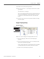
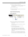
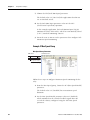
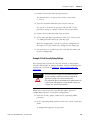
Introduction . . . . . . . . . . . . . . . . . . . . . . . . .
Example Application 1 . . . . . . . . . . . . . . . . .
Example 1: Initial Security Group Settings .
Example 1: General Group Settings . . . . .
Example 1: Feedback Group Settings . . . .
Example 1: Stop Group Settings . . . . . . . .
Example 1: Limited Speed Group Settings .
Example 1: Door Control Group Settings .
Example 1: Max Speed Group . . . . . . . . .
Example 1: Final Security Group Settings .
Example Application 2 . . . . . . . . . . . . . . . . .
Example 2: Initial Security Group Settings .
Example 2: General Group Settings . . . . .
Example 2: Feedback Group Settings . . . .
Example 2: Stop Group Settings . . . . . . . .
Example 2: Limited Speed Group Settings .
Example 2: Door Control Group Settings .
Example 2: Max Speed Group . . . . . . . . .
Example 2: Final Security Group Settings .
.
.
.
.
.
.
.
.
.
.
.
.
.
.
.
.
.
.
.
.
.
.
.
.
.
.
.
.
.
.
.
.
.
.
.
.
.
.
.
.
.
.
.
.
.
.
.
.
.
.
.
.
.
.
.
.
.
.
.
.
.
.
.
.
.
.
.
.
.
.
.
.
.
.
.
.
.
.
.
.
.
.
.
.
.
.
.
.
.
.
.
.
.
.
.
.
.
.
.
.
.
.
.
.
.
.
.
.
.
.
.
.
.
.
.
.
.
.
.
.
.
.
.
.
.
.
.
.
.
.
.
.
.
.
.
.
.
.
.
.
.
.
.
.
.
.
.
.
.
.
.
.
.
.
.
.
.
.
.
.
.
.
.
.
.
.
.
.
.
.
.
.
.
.
.
.
.
.
.
.
.
.
.
.
.
.
.
.
.
.
161
161
162
163
164
166
168
169
170
171
172
173
174
175
177
179
181
182
183
............
............
............
............
............
............
............
............
Stopping Faults
............
............
............
............
.
.
.
.
.
.
.
.
.
.
.
.
.
.
.
.
.
.
.
.
.
.
.
.
.
.
185
185
186
187
187
187
190
190
191
192
192
195
196
Chapter 12
Troubleshoot the MSR57P Relay
Publication 440R-UM004A-EN-P - December 2008
Introduction . . . . . . . . . . . . . . . . . . . . .
Status Indicators . . . . . . . . . . . . . . . . . .
Nonrecoverable Faults. . . . . . . . . . . . . .
Fault Recovery . . . . . . . . . . . . . . . . . . .
Input and Output Faults . . . . . . . . . . . .
Fault Codes and Descriptions . . . . . . . .
Fault Reactions . . . . . . . . . . . . . . . . . . .
Safe State Faults . . . . . . . . . . . . . . . .
Stop Category Faults and Fault While
Status Attributes . . . . . . . . . . . . . . . . . .
Guard Status Attributes. . . . . . . . . . .
I/O Diagnostic Status Attributes . . . .
Configuration Fault Codes . . . . . . . . . . .
7
Table of Contents
Appendix A
Specifications
Introduction . . . . . . . . . . . . .
General Specifications . . . . . .
Environmental Specifications .
Certifications. . . . . . . . . . . . .
Encoder Specifications. . . . . .
.
.
.
.
.
.
.
.
.
.
.
.
.
.
.
.
.
.
.
.
.
.
.
.
.
.
.
.
.
.
.
.
.
.
.
.
.
.
.
.
.
.
.
.
.
.
.
.
.
.
.
.
.
.
.
.
.
.
.
.
.
.
.
.
.
.
.
.
.
.
.
.
.
.
.
.
.
.
.
.
.
.
.
.
.
.
.
.
.
.
.
.
.
.
.
.
.
.
.
.
.
.
.
.
.
.
.
.
.
.
197
197
198
199
199
Appendix B
Parameter Data
Parameter Groups . . . . . . . . . . . . . . . . . . . . . . . . . . . . . . . 201
Parameters and Settings in a Linear List . . . . . . . . . . . . . . . 202
Appendix C
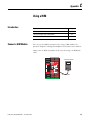
Using a HIM
Introduction . . . . . . . . . . . . . . . . . . . .
Connect a HIM Module . . . . . . . . . . . .
Setting Parameters with a HIM Module.
Accessing the Fault History Queue. . . .
.
.
.
.
.
.
.
.
.
.
.
.
.
.
.
.
.
.
.
.
.
.
.
.
.
.
.
.
.
.
.
.
.
.
.
.
.
.
.
.
.
.
.
.
.
.
.
.
.
.
.
.
.
.
.
.
.
.
.
.
213
213
214
215
Introduction . . . . . . . . . . . . . . . . . . . . . . . . .
Connect a Personal Computer . . . . . . . . . . . .
Using DriveExplorer Software . . . . . . . . . . . .
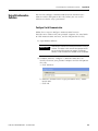
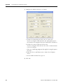
Configure Serial Communication. . . . . . . .
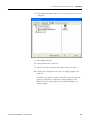
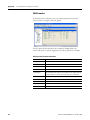
Edit Parameters in DriveExplorer Software
Access the Fault History Queue . . . . . . . .
Using DriveExecutive Software . . . . . . . . . . .
Configure Serial Communication. . . . . . . .
Edit Parameters . . . . . . . . . . . . . . . . . . . .
.
.
.
.
.
.
.
.
.
.
.
.
.
.
.
.
.
.
.
.
.
.
.
.
.
.
.
.
.
.
.
.
.
.
.
.
.
.
.
.
.
.
.
.
.
.
.
.
.
.
.
.
.
.
.
.
.
.
.
.
.
.
.
.
.
.
.
.
.
.
.
.
.
.
.
.
.
.
.
.
.
.
.
.
.
.
.
.
.
.
217
217
218
218
219
220
221
221
224
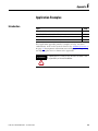
Introduction . . . . . . . . . . . . . . . . . . . . . . . . . . . . . . . . . . .
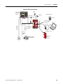
PowerFlex 70 Drive with Safe-Off Application Example . . .
PowerFlex 700 Drive without Safe-Off . . . . . . . . . . . . . . . .
Kinetix 6000 or Kinetix 7000 Drives with Safe-off Example .
Kinetix 2000 Drive without Safe-off Example . . . . . . . . . . .
227
228
231
233
235
Appendix D
Use DriveExplorer or
DriveExecutive Software
Appendix E
Application Examples
Index
8
Publication 440R-UM004A-EN-P - December 2008
Preface
About This Publication
This manual explains how the Guardmaster MSR57P Speed Monitoring
Safety Relay can be used in Safety Integrity Level (SIL) 3, Performance
Level [PL(e)], or Category (CAT) 4 applications. It describes the safety
requirements, including PFD and PFH values and application
verification information, and provides information on installing,
configuring, and troubleshooting the relay.
Who Should Use This
Manual
Use this manual if you are responsible for designing, installing,
configuring, or troubleshooting safety applications that use the
MSR57P Speed Monitoring Safety Relay.
You must have a basic understanding of electrical circuitry and
familiarity with relay logic. You must also be trained and experienced
in the creation, operation, and maintenance of safety systems.
Conventions
In this manual, configuration parameters are listed by number
followed by the name in brackets. For example,
P24 [OverSpd Response].
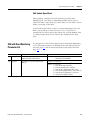
Terminology
The following table defines terms used in this manual.
Terminology
Abbreviation
Full Term
Definition
1oo2
One out of Two
Refers to the behavioral design of a dual-channel safety system.
CAT
Category
DC
Door Control
—
DM
Door Monitoring
—
EN
European Norm
The official European Standard.
ESM
Enabling Switch Monitoring
—
ESPE
Electro-sensitive Protective
Equipment
An assembly of devices and/or components working together for protective
tripping or presence-sensing purposes and comprising as a minimum:
• a sensing device.
• controlling/monitoring devices.
• output signal-switching devices (OSSD).
FMEA
Failure Mode and Effects Analysis
Analysis of potential failure modes to determine the effect upon the system
and identify ways to mitigate those effects.
IEC
International Electrotechnical
Commission
—
9Publication 440R-UM004A-EN-P - December 2008
9
Preface
Terminology
Abbreviation
Full Term
Definition
IGBT
Insulated Gate Bi-polar Transistor
—
HFT
Hardware Fault Tolerance
The HFT equals n, where n+1 faults could cause the loss of the safety function.
An HFT of 1 means that 2 faults are required before safety is lost.
HIM
Human Interface Module
A module used to configure a device.
LM
Lock Monitoring
—
MP
Motion Power
—
OSSD
Output Signal Switching Device
The component of the electro-sensitive protective equipment (ESPE) connected
to the control system of a machine, which, when the sensing device is
actuated during normal operation, responds by going to the OFF-state.
PC
Personal Computer
Computer used to interface with and program your safety system.
PFD
Probability of Failure on Demand
The average probability of a system to fail to perform its design function on
demand.
PFH
Probability of Failure per Hour
The probability of a system to have a dangerous failure occur per hour.
PL
Performance Level
ISO 13849-1 safety rating
RL
Reset Loop
—
SDM
Safe Direction Monitoring
—
SFF
Safe Failure Fraction
The sum of safe failures plus the sum of dangerous detected failures divided
by the sum of all failures.
SIL
Safety Integrity Level
A measure of a products ability to lower the risk that a dangerous failure could
occur.
SLS
Safe Limited Speed
—
SMA
Safe Maximum Acceleration
—
SMS
Safe Maximum Speed
—
SS
Safe Stop
—
10
Publication 440R-UM004A-EN-P - December 2008
Preface
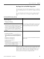
Additional Resources
This table lists publications that contain important information about
safety systems that can use the speed monitoring safety functions of
the MSR57P relay.
Resource
Description
Guardmaster MSR57P Speed Monitoring Safety Relay Installation Provides information on installing the MSR57P relay.
Instructions, publication 440R-IN016
HIM Quick Reference, publication 20HIM-QR001
A quick reference for using the HIM keypad.
DriveExplorer Online Help
DriveExplorer online help provides information on the release, quick
start steps, general information about DriveExplorer software,
descriptions of the elements in the DriveExplorer window, step-by-step
procedures, and troubleshooting information.
PowerFlex USB Converter User Manual, publication
DRIVES-UM001
Provides detailed information on installing, configuring, and
troubleshooting the 1203-USB converter.
PowerFlex Smart Self-powered Serial Converter User Manual,
publication 20COMM-UM001
Provides detailed information on installing, configuring, and
troubleshooting the 1203-SSS series B serial converter.
PowerFlex 700S Phase II Drive User Manual, publication
20D-UM006
Provides detailed information on installing, wiring, programming, and
troubleshooting PowerFlex 700S Phase II drives.
PowerFlex 700 Series A User Manual, publication 20B-UM001
Provides detailed information on installing, wiring, programming, and
troubleshooting PowerFlex 700 Series A drives.
PowerFlex 700 Series B User Manual, publication 20B-UM002
Provides detailed information on installing, wiring, programming, and
troubleshooting PowerFlex 700 Series B drives.
PowerFlex 70 User Manual, publication 20A-UM001
Provides detailed information on installing, wiring, programming, and
troubleshooting PowerFlex 70 drives.
PowerFlex Reference Manual, publication PFLEX-RM001
Provides specifications and dimensions, as well as detailed information
about drive operation.
DriveGuard Safe-Off Option (Series B) for PowerFlex 40P and 70
AC Drives User Manual, publication PFLEX-UM003
Provides detailed information installing, wiring, and operating
PowerFlex 70 AC drives with the Safe-Off option. The manual also
includes certification information for the Safe-Off option.
Kinetix 6000 Multi-axis Servo Drive User Manual, publication
2094-UM001
Provides detailed information on installing, connecting, configuring, and
troubleshooting a Kinetix 6000 drive. The manual also includes
specifications and dimensions.
Kinetix Safe-off Feature Safety Reference Manual, publication
GMC-RM002
Provides detailed information on the safety requirements, as well as
connector and wiring diagrams for the Safe-off feature.
Kinetix Motion Control Selection Guide, publication GMC-SG001
Provides features, specifications, and dimensions for selecting Kinetix
Motion Control servo drives, motors, actuators, and accessory
components.
Ultra3000 Digital Servo Drives Installation Manual, publication
2098-IN003
Provides information on installing and wiring for the Ultra3000 Digital
Servo Drives.
Ultra3000 Digital Servo Drives Integration Manual, publication
2098-IN005
Provides power-up procedures, system integration, and troubleshooting
tables for the Ultra3000 Digital Servo Drives.
Safety Guidelines for the Application, Installation and
Maintenance of Solid State Control, publication SGI-1.1
Describes important differences between solid state control and
hard-wired electromechanical devices.
You can view or download publications at:
http://literature.rockwellautomation.com. To order paper copies of
technical documentation, contact your local Rockwell Automation
distributor or sales representative.
Publication 440R-UM004A-EN-P - December 2008
11
Preface
12
Publication 440R-UM004A-EN-P - December 2008
Chapter
1
Safety Concept
Introduction
This chapter describes the safety performance level concept and how
the MSR57P Speed Monitoring Safety Relay can meet the requirements
for SIL CL3, PL(e), or CAT 4 applications.
Topic
Safety Certification
Page
Safety Certification
13
Functional Proof Tests
16
PFD and PFH Definitions
16
PFD and PFH Data
17
Safe State
17
Safety Reaction Time
18
Considerations for Safety Ratings
18
Contact Information if Device Failure Occurs
22
The MSR57P Speed Monitoring Safety Relay is certified for use in
safety applications up to and including SIL CL3 according to IEC 61508
and EN 62061, Performance Level PL(e) and CAT 4 according to
ISO 13849-1. Safety requirements are based on the standards current
at the time of certification.
The TÜV Rheinland group has approved the MSR57P Speed
Monitoring Safety Relay for use in safety-related applications where
the de-energized state is considered to be the safe state. All of the
examples related to I/O included in this manual are based on
achieving de-energization as the safe state for typical Machine Safety
and Emergency Shutdown (ESD) systems.
13Publication 440R-UM004A-EN-P - December 2008
13
Chapter 1
Safety Concept
Important Safety Considerations
The system user is responsible for:
• the set-up, safety rating, and validation of any sensors or
actuators connected to the system.
• completing a system-level risk assessment and reassessing the
system any time a change is made.
• certification of the system to the desired safety performance
level.
• project management and proof testing.
• programming the application software and the device
configurations in accordance with the information in this
manual.
• access control to the system, including password handling.
• analyzing all configuration settings and choosing the proper
setting to achieve the required safety rating.
IMPORTANT
ATTENTION
ATTENTION
When applying Functional Safety, restrict access to qualified,
authorized personnel who are trained and experienced.
When designing your system, consider how personnel will exit
the machine if the door locks while they are in the machine.
Additional safeguarding devices may be required for your
specific application.
A HIM module may be used to configure and monitor the
MSR57P speed monitoring safety relay. However, the stop
button on the HIM does not have safety integrity and must not
be used to execute a safe stop.
The stop button setting is not maintained through a power
cycle. Do not use the stop button in conjunction with an
Automatic Reset configuration. Unintended motion could result.
14
Publication 440R-UM004A-EN-P - December 2008
Safety Concept
Chapter 1
Safety Category 4 Performance Definition
To achieve Safety Category 4 according to ISO 13849-1:2006, the
safety-related parts have to be designed such that:
• the safety-related parts of machine control systems and/or their
protective equipment, as well as their components, shall be
designed, constructed, selected, assembled, and combined in
accordance with relevant standards so that they can withstand
expected conditions.
• basic safety principles shall be applied.
• a single fault in any of its parts does not lead to a loss of safety
function.
• a single fault is detected at or before the next demand of the
safety function, or, if this detection is not possible, then an
accumulation of faults shall not lead to a loss of the safety
function.
• the average diagnostic coverage of the safety-related parts of the
control system shall be high, including the accumulation of
faults.
• the mean time to dangerous failure of each of the redundant
channels shall be high.
• measures against common cause failure shall be applied.
Stop Category Definitions
The selection of a stop category for each stop function must be
determined by a risk assessment.
• Stop Category 0 is achieved with immediate removal of power to
the actuator, resulting in an uncontrolled coast to stop. Safe
Torque Off accomplishes a Stop Category 0 stop.
• Stop Category 1 is achieved with power available to the machine
actuators to achieve the stop. Power is removed from the
actuators when the stop is achieved.
• Stop Category 2 is a controlled stop with power available to the
machine actuators. The stop is followed by a holding position
under power.
IMPORTANT
Publication 440R-UM004A-EN-P - December 2008
When designing the machine application, timing and distance
should be considered for a coast to stop (Stop Category 0 or
Safe Torque Off). For more information regarding stop
categories, refer to EN 60204-1.
15
Chapter 1
Safety Concept
Performance Level and Safety Integrity Level (SIL) 3
For safety-related control systems, Performance Level (PL), according
to ISO 13849-1, and SIL levels, according to IEC 61508 and EN 62061,
include a rating of the system’s ability to perform its safety functions.
All of the safety-related components of the control system must be
included in both a risk assessment and the determination of the
achieved levels.
Refer to the ISO 13849-1, EN 61508, and EN 62061 standards for
complete information on requirements for PL and SIL determination.
See Chapter 10, Safety Configuration and Verification, for more
information on the requirements for configuration and verification of a
safety-related system containing the MSR57P Speed Monitoring Safety
Relay.
Functional Proof Tests
The functional safety standards require that functional proof tests be
performed on the equipment used in the system. Proof tests are
performed at user-defined intervals and are dependent upon PFD and
PFH values.
IMPORTANT
PFD and PFH Definitions
Your specific application determines the time frame for the
proof test interval.
Safety-related systems can be classified as operating in either a Low
Demand mode, or in a High Demand/Continuous mode.
•
Low Demand mode: where the frequency of demands for
operation made on a safety-related system is no greater than one
per year or no greater than twice the proof-test frequency.
•
High Demand/Continuous mode: where the frequency of
demands for operation made on a safety-related system is greater
than once per year or greater than twice the proof test interval.
The SIL value for a low demand safety-related system is directly
related to order-of-magnitude ranges of its average probability of
failure to satisfactorily perform its safety function on demand or,
simply, average probability of failure on demand (PFD). The SIL value
for a High Demand/continuous mode safety-related system is directly
related to the probability of a dangerous failure occurring per hour
(PFH).
16
Publication 440R-UM004A-EN-P - December 2008
Safety Concept
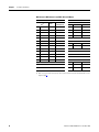
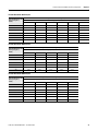
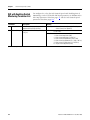
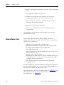
PFD and PFH Data
Chapter 1
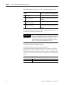
These PFD and PFH calculations are based on the equations from
Part6 of EN 61508 and show worst-case values.
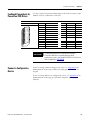
This table provides data for a 20-year proof test interval and
demonstrates the worst-case effect of various configuration changes
on the data.
PFD and PFH for 20-year Proof Test Interval
Attribute
Pulse Test ON
Pulse Test OFF(1)
Single Encoder
Dual Encoder
PFD
1.23E - 04
5.93E-04
25.9E-04
PFH
7.04E-09
3.38E-09
14.8E-09
SFF
99.3%
99.2%
97.9%
(1) Pulse testing for outputs is configured using the following parameters: P71 [MP Out Mode], P72 [SS Out Mode],
P73 [SLS Out Mode], P74 [Door Out Mode]. If you disable pulse-testing on any of these outputs, the achievable
SIL, Category, and PL ratings of your entire MSR57P safety system are reduced. See Outputs beginning on page
63 for more information.
Safe State
The Safe State encompasses all operation that occurs outside of the
other monitoring and stopping behavior defined as part of the speed
monitoring safety relay. In addition, configuration takes place in the
Safe State. While the relay is in the Safe State, all safety control
outputs, except the Door Control (DC_Out) output, are in their safe
state (de-energized). The Door Control (DC_Out) output will be in
either the locked state or in the de-energized state depending upon
the condition that resulted in the safe state.
The diagnostic Fault_Status output may be on in the safe state.
When you cycle power, the relay enters the Safe State for self-testing.
If the self-tests pass and there is a valid configuration, the relay
remains in the Safe State until a successful request for safe speed
monitoring occurs.
If a Safe State Fault is detected, the relay goes to the Safe State. This
includes faults related to integrity of hardware or firmware.
For more information on faults, see Chapter 12, Troubleshoot the
MSR57P Relay.
Publication 440R-UM004A-EN-P - December 2008
17
Chapter 1
Safety Concept
Safety Reaction Time
The safety reaction time is the amount of time from a safety-related
event as input to the system until the system is in the Safe State.
The safety reaction time from an input signal condition that triggers a
safe stop, to the initiation of the configured Safe Stop Type, is 20 ms
(maximum).
The safety reaction time from an overspeed event that triggers a safe
stop, to the actual initiation of the configured Safe Stop Type, is equal
to the value of the P24 [OverSpd Response] parameter.
For more information on overspeed response time, see Overspeed
Response Time on page 75.
Considerations for Safety
Ratings
The achievable safety rating of an application using the MSR57 relay is
dependent upon many factors, including the encoder setup, drive
options, output pulse testing, and the type of motor.
When using two independent encoders to monitor motion and when
installed in a manner to avoid any common cause dangerous failure,
the MSR57P relay can be used in applications up to and including
SIL CL3, PL(e), and CAT 4.
When using a drive with the Safe-Off option and one external
contactor, or when using two external contactors, the MSR57P relay
can be used in applications up to and including SIL CL3, PL(e), and
CAT 4.
IMPORTANT
18
Some of the diagnostics performed on the encoder signals
require motion to detect faults. You must make sure that motion
occurs at least once every six months.
Publication 440R-UM004A-EN-P - December 2008
Safety Concept
Chapter 1
Output Pulse Test Considerations
If the pulse testing of any safety output is disabled, the maximum
safety rating will be up to and including SIL CL2, PL(d), and CAT 3 for
any safety chain incorporating any input or output of the MSR57P relay.
IMPORTANT
Setting any of the P71 [MP_Out Mode], P72 [SS_Out Mode],
P73 [SLS_Out Mode], or P74 [DC_Out Mode] parameters to 1 =
No Pulse Test disables internal diagnostics as well as external
diagnostics required to achieve higher safety ratings.
You must exercise the SS_In input at least once every six
months.
You may need to disable pulse-testing if the connected device does
not support OSSD inputs. Refer to the product documentation for your
connected device.
Considerations for Single-encoder Applications
When configured correctly, the MSR57P relay performs these
diagnostics on the encoder:
•
•
•
•
Sin2 + Cos2 diagnostic.
detection of open or short-circuit.
encoder supply voltage monitoring.
detection of illegal quadrature transitions of the sine and cosine
signals.
A safety rating up to and including SIL CL3, PL(e), and CAT 4 can be
achieved in a single-encoder application with these requirements:
• The motor is a permanent magnet (PM) brushless AC motor.
• The motor controller must be configured as a closed-loop
application with field-oriented control using the single-encoder
for commutation.
• The motor-to-encoder coupling is designed to exclude shaft
slippage as a dangerous failure mechanism.
• The MSR57P relay is configured for Sin/Cos encoder type.
Publication 440R-UM004A-EN-P - December 2008
19
Chapter 1
Safety Concept
• The encoder is of the Sin/Cos type and is suitable for the desired
safety rating of the application.
An encoder that is suitable for SIL CL3 applications must:
– use independent Sine/Cosine signals.
– be incapable of producing simulated signals when under an
error condition.
– use simple or discreet circuitry with no complex or
programmable internal devices.
• The controller is not configured for auto transition to
encoderless commutation in the event of encoder failure.
• The motor controller must use the same encoder signals as
MSR57P relay.
• Encoder voltage monitoring in MSR57P relay must be enabled.
• The system design of the motor/encoder-to-load coupling
excludes shaft slippage and breakage as a dangerous failure
mechanism.
Single-encoder with Kinetix Drive
A safety rating up to and including SIL CL3, PL(e), and CAT 4 can be
achieved in an MSR57P relay single-encoder application when the
relay is used in conjunction with a properly-configured Kinetix Servo
Drive with Safe-Off and any motor/encoder combination that meets
the single-encoder application requirements on page 19.
Single-encoder with PowerFlex Drive
A safety rating up to and including SIL CL3, PL(e), and CAT 4 can be
achieved in an MSR57P relay single-encoder application when the
relay is used in conjunction with a properly-configured
PowerFlex 700S or PowerFlex 755 drive and any motor/encoder
combination that meets the single-encoder application requirements
on page 19.
20
Publication 440R-UM004A-EN-P - December 2008
Safety Concept
Chapter 1
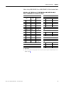
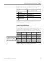
For example, to properly configure a PowerFlex 700S drive to meet
the single-encoder application requirements listed on page 19, make
these parameter settings.
Parameter
Number
Parameter
Name
Required Drive
Addresses Single-encoder
Parameter Setting Requirement
P485
Motor Ctrl Mode 2 = Pmag Motor
P222
Mtr Fdbk Sel Pri
5 = FB Opt Port0
P153, bit 16
Control Options
OFF = Auto Tach Sw The controller is not configured
for auto transition to
encoderless commutation in the
event of encoder failure.
The motor controller must be
configured as a closed-loop
application with field-oriented
control using the single-encoder
for commutation.
You must make sure that a Sin/Cos feedback option is installed in the
drive. The drive must be commissioned according to the normal
startup procedure for proper operation in your system.
The MSR57P is suitable for SIL CL3, Cat 4 applications when
connected to drives which also support Cat 4 applications. Some
applications may require an external contactor to meet Cat 4
requirements. Refer to your drive manual for details on safety
requirements.
Refer to the PowerFlex 700S Phase II Drive User Manual, publication
20D-UM006 for detailed information on installing, configuring, and
operating a PowerFlex 700S drive.
Understanding Commutation
Permanent magnet (PM), brushless AC motors, like those listed above,
are a class of synchronous motor that depend on electronic brushless
commutation to generate torque and motion. In PM brushless motors,
an electromagnetic field is created by the permanent magnets on the
rotor. A rotating magnetic field is created by a number of
electromagnets commutated electronically with insulated-gate bipolar
transistors (IGBT’s) at the right speed, order, and times. Movement of
the electromagnetic field is achieved by switching the currents in the
coils of the stator winding. This process is called commutation.
Interaction of the two electromagnetic fields produces magnetic force
or torque.
Excessive noise, broken encoder wires, and loss of the encoder power
supply are factors that can affect commutation while the motor is
running. To prevent the motor from spinning, these conditions can be
detected by the drive with the use of safety monitoring circuits.
Publication 440R-UM004A-EN-P - December 2008
21
Chapter 1
Safety Concept
Contact Information if
Device Failure Occurs
22
If you experience a failure with any safety-certified device, contact
your local Rockwell Automation distributor. With this contact, you
can:
•
return the device to Rockwell Automation so the failure is
appropriately logged for the catalog number affected and a record
is made of the failure.
•
request a failure analysis (if necessary) to determine the probable
cause of the failure.
Publication 440R-UM004A-EN-P - December 2008
Chapter
2
About the MSR57P Speed Monitoring Safety
Relay
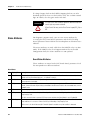
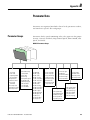
Introduction
This chapter describes the features of the MSR57P Speed Monitoring
Safety Relay.
Topic
Safety Functions
Page
Safety Functions
23
Hardware Features
26
Configuration
27
The MSR57P Speed Monitoring Safety Relay features five inputs, three
sets of safety outputs, and one bipolar safety output. Each of the
inputs supports a specific safety function.
•
•
•
•
•
Safe Stop (SS)
Safe Limited Speed Monitoring (SLS)
Door Monitoring (DM)
Enabling Switch Monitoring (ESM)
Lock Monitoring (LM)
An additional reset input provides for reset and monitoring of the
safety circuit.
The relay can be used in single-axis or multi-axis applications, and the
relay is configurable as a master or slave based on its location in the
system.
23Publication 440R-UM004A-EN-P - December 2008
23
Chapter 2
About the MSR57P Speed Monitoring Safety Relay
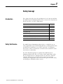
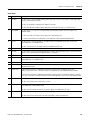
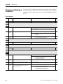
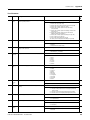
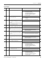
Safety Modes
The relay can be configured to operate in one of 11 user-selectable
safety modes, based on combinations of the safety functions listed on
the previous page. The relay monitors motion for Safe Stop in every
mode except Disabled.
Safety Mode
Page
Disabled – In this mode, all safety functions are disabled.
24
Safe Stop – The relay activates the configured Safe Stop Type upon deactivation
of the Safe Stop input or the occurrence of a Stop Category Fault.
89
Safe Stop with Door Monitoring – In addition to monitoring for Safe Stop, the
relay monitors the status of the door.
102
Safe Limited Speed – In addition to monitoring for Safe Stop, the relay monitors
the feedback velocity and compares it to a configurable Safe Speed Limit. If the
velocity exceeds the limit, the relay initiates the configured Safe Stop Type.
105
Safe Limited Speed with Door Monitoring – In addition to monitoring for Safe Stop
and Safe Limited Speed, the relay monitors the status of the door.
110
Safe Limited Speed with Enabling Switch Control – In addition to monitoring for
Safe Stop and Safe Limited Speed, the relay monitors the status of the Enabling
Switch input.
112
Safe Limited Speed with Door Monitor and Enabling Switch – In addition to
monitoring for Safe Stop and Safe Limited Speed, the relay monitors the status of
the door and the Enabling Switch input.
115
Safe Limited Speed (status only) – In addition to monitoring for Safe Stop, the
relay monitors the feedback velocity and compares it to a configurable Safe Speed
Limit. If the velocity exceeds the limit, the system status is made available as a
safe output intended for a safety programmable logic controller. No stopping
action takes place.
119
Slave, Safe Stop – The relay performs the same functions as Safe Stop. However,
it regards the Door Monitor input as a Door Control output from an upstream axis,
and performs a logical AND with its internal Door Control signal to form the
cascaded Door Control output.
125
Slave, Safe Limited Speed – The relay performs the same functions as Safe
Limited Speed mode. However, it regards the Door Monitor input as a Door Control
output from an upstream axis, and performs a logical AND with its internal Door
Control signal to form the cascaded Door Control output.
132
Slave, Safe Limited Speed (status only) – The relay performs the same functions
as Safe Limited Speed Status Only mode. However, it regards the Door Monitor
input as a Door Control output from an upstream axis, and performs a logical AND
with its internal Door Control signal to form the cascaded Door Control output.
135
Disabled Mode
In Disabled mode, all safety functions are disabled. Input, output, or
speed monitoring diagnostics do not take place and all outputs are in
their safe state.
24
Publication 440R-UM004A-EN-P - December 2008
About the MSR57P Speed Monitoring Safety Relay
Chapter 2
Lock Monitoring
Lock monitoring helps prevent access to the hazard during motion. In
many applications, it is not sufficient for the machine to initiate a stop
command once the door has been opened because a high inertia
machine may take a long time to stop. Preventing access to the hazard
until a safe speed has been detected may be the safest condition. The
lock monitoring feature is used to verify the operation of the door
locking mechanism.
Lock monitoring can be enabled on single units or on the first unit in
a multi-axis system. If the Lock Monitor input (LM_In) indicates that
the door is unlocked when the Door Control output (DC_Out) is in
the locked state, or if the Lock Monitor input indicates locked when
the Door Monitor input (DM_In) transitions from closed to open, the
configured Safe Stop Type is initiated.
Safe Maximum Speed, Safe Maximum Acceleration, and Safe
Direction Monitoring
Three additional safety functions, Safe Maximum Speed (SMS), Safe
Maximum Acceleration (SMA) and Safe Direction Monitoring (SDM),
operate independent of the other modes, relying on the Safe Stop
function. When you configure the relay for Safe Maximum Speed, the
feedback velocity is monitored and compared against a
user-configurable limit. If the measured velocity is greater than or
equal to the limit, the configured Safe Stop type is executed.
When Safe Acceleration Monitoring is enabled, the relay monitors the
acceleration rate and compares it to a configured Safe Maximum
Acceleration Limit. If acceleration is detected as greater than or equal
to the Safe Maximum Acceleration Limit, an Acceleration Fault occurs.
If an Acceleration Fault is detected while the relay is actively
monitoring motion, the configured Safe Stop type is initiated.
Safe Direction Monitoring is also activated via device configuration.
The relay monitors the feedback direction and executes the
configured Safe Stop type when motion in the illegal direction is
detected.
See Chapter 9, Safe Maximum Speed and Direction Monitoring, for
detailed information on these functions.
Publication 440R-UM004A-EN-P - December 2008
25
Chapter 2
About the MSR57P Speed Monitoring Safety Relay
Hardware Features
The MSR57P relay features five dual-channel inputs, three sets of
sourcing safety outputs, and one bipolar safety output. You can
configure dual-channel inputs to accept contact devices with two
normally closed contacts, or one normally closed and one normally
open contact. They can also be configured for single channel
operation.
IMPORTANT
Single-channel operation does not meet SIL CL3, PL(e), Cat 4
safety integrity.
These inputs also support output signal switching devices (OSSD).
Each output has integral pulse-test checking circuitry. Two RJ-45
connectors support encoder inputs. The MSR57P relay features status
indicators and status data for troubleshooting.
26
Publication 440R-UM004A-EN-P - December 2008
About the MSR57P Speed Monitoring Safety Relay
Configuration
Chapter 2
Configure the MSR57P relay by setting the configuration parameters
using a HIM module (catalog number 20-HIM-A3). You can also use
DriveExplorer software, version 5.02 or later, or DriveExecutive
software(1), version 4.01 or later. All of these configuration tools let
you save the configuration and download it to another MSR57P relay.
Only DriveExecutive software lets you edit the configuration offline.
When the relay configuration is complete, it can be safety-locked to
prevent unauthorized changes to the safety configuration. If you set a
password to protect the safety configuration, you must enter the
password before you can lock or unlock the configuration.
If you are using a HIM to configure the relay, see Appendix C for
information on connecting a HIM and setting parameters with the
keypad. If you are using software to configure the relay, see Appendix
D for information on connecting to a personal computer and using the
software.
(1)
Publication 440R-UM004A-EN-P - December 2008
RSLinx software, version 2.50.00 or later, is required for DriveExecutive software.
27
Chapter 2
28
About the MSR57P Speed Monitoring Safety Relay
Publication 440R-UM004A-EN-P - December 2008
Chapter
3
Installation and Wiring
Introduction
This chapter provides details on connecting devices and wiring the
MSR57P relay.
Topic
Environment and Enclosure
31
General Safety Information
30
Dimensions
31
Spacing Requirements
32
Mount the MSR57P Relay
32
Power Supply Requirements
32
Removable Terminal Blocks
33
Circuit Diagram
33
Terminal Connections
34
Compatible Encoders
35
Connect an Encoder
36
Encoder Cable Specifications
42
Feedback Cable Connections for Kinetix 2000, Kinetix 6000, Kinetix 7000
and Ultra3000 Drives
42
Feedback Connections for PowerFlex 70 Drives
52
Feedback Connections for PowerFlex 700S Drives
55
Connect a Configuration Device
55
ATTENTION
29Publication 440R-UM004A-EN-P - December 2008
Page
This device is intended to be part of the safety-related control
system of a machine. Before installation, a risk assessment
should be performed to determine whether the specifications
of this device are suitable for all foreseeable operational and
environmental characteristics for the system to which it is to be
installed.
29
Chapter 3
Installation and Wiring
General Safety Information
WARNING
Use this product for its intended applications.
This equipment must not be used for unintended applications, nor in ways that do not conform to appropriate safety
standards and good practices. The safety functions may not operate properly, or at all, if this equipment is not used for
the intended purposes.
Use within specified operating limits.
This product and the equipment on which it is installed, persons handling the product and the equipment, and/or the
immediate environment can be harmed if this equipment is operated outside the specified limits of any of its technical
specifications.
Installation and operation must be performed only by qualified technical personnel.
This equipment is to be installed, started up, and operated only by technical personnel who have been trained and
understand:
• the products covered by this publication.
• directives, regulations, and good practices relating to machine safety.
• instrumentation and automation components, equipment, and systems.
• industrial electrical practices.
Up-to-date user documentation must be readily accessible by technical personnel.
The latest version of user documentation that includes instructions for installation, operation, and maintenance of this
product must be readily available to personnel involved in any of these tasks.
Identify hazardous areas and dangerous operating modes before using the product.
Machine safety applications make it necessary for hazardous areas and dangerous operating modes to be carefully
identified, and adequate measures taken to be sure that failure or tampering does not allow automated equipment to be
of risk to personnel.
Observe electrical safety regulations and good practices.
Electrical safety regulations stipulated by the appropriate technical authorities must be observed.
Do not use the product if it is damaged or diminished in any way.
Carefully inspect the product before it is installed, or reinstalled. If, at any time, the condition of the product is observed
to be diminished in any way so that there is even the slightest possibility of incorrect functioning, you should assume that
safe operation is no longer possible, and the equipment should be removed from the system immediately so that
unintentional operation is impossible. Examples of such conditions are:
• visible damage to the equipment.
• loss of electrical functions.
• exposure to temperatures higher than the specified operating limit.
• visible indication of burning.
• physical damage due to impact or excessive mechanical shock.
Observe all electrical safety regulations stipulated by the appropriate
technical authorities.
ATTENTION
30
Make sure that electrical power supply to the MSR57P relay is
switched off before making or removing any electrical
connections.
Publication 440R-UM004A-EN-P - December 2008
Installation and Wiring
Chapter 3
Environment and Enclosure
IMPORTANT
This product must be installed inside protected control panels
or cabinets appropriate for the environmental conditions of the
industrial location. The protection class of the panel or cabinet
should be IP54 or higher.
See the specifications in Appendix A.
Considerations for
Reducing Noise
To reduce the affects of electromagnetic interference (EMI), follow
these guidelines when connecting your system:
• Keep wire lengths as short as possible.
• Route signal cables away from motor and power wiring.
• Ground all equipment, following the manufacturers instructions.
Additional noise reduction techniques may be necessary.
Refer to the System Design for Control of Electrical Noise Reference
Manual, publication GMC-RM001 for more information.
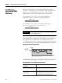
Dimensions
Publication 440R-UM004A-EN-P - December 2008
31
Chapter 3
Installation and Wiring
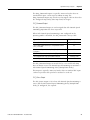
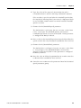
Spacing Requirements
Adequate air space must be provided around the system (module
cluster). Minimum recommended clearances:
• 15 mm (0.6 in.) above
• 15 mm (0.6 in.) below
• 2…3 mm (0.08…0.12 in.) between modules at ambient
temperatures higher than 40 °C (104 °F).
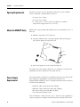
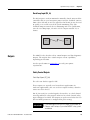
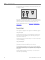
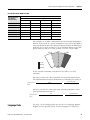
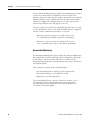
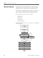
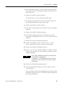
Mount the MSR57P Relay
Follow these steps to mount the MSR57P relay to an EN50022 -35 x 7.5
DIN rail.
1. Hook the top slot over the DIN rail.
2. Snap the bottom of the relay into position while pressing the
relay down against the top of the rail.
Slot
DIN Rail
Latch
3. Attach end plates on each end of the DIN rail.
To remove the relay from the DIN rail, use a flathead screwdriver to
pull down the latch and lift the relay from the rail.
Power Supply
Requirements
The external power supply must conform to the Directive 2006/95/EC
Low Voltage, by applying the requirements of EN61131-2
Programmable Controllers, Part 2 - Equipment Requirements and Tests
and one of the following:
•
•
•
•
EN60950- SELV (Safety Extra Low Voltage)
EN60204 - PELV (Protective Extra Low Voltage)
IEC 60536 Safety Class III (SELV or PELV)
UL 508 Limited Voltage Circuit
To meet EN60204 - PELV, 24V DC + 10% - 20% has to be supplied by
a power supply that complies with IEC/EN60204 and IEC/EN 61558-1.
32
Publication 440R-UM004A-EN-P - December 2008
Installation and Wiring
Chapter 3
Such a power supply meets the electrical safety requirements and
maintains minimum power of 19.2V DC during 20 ms even in the
event of voltage dips.
For planning information, refer to the guidelines in Industrial
Automation Wiring and Grounding Guidelines, Allen-Bradley
publication 1770-4.1.
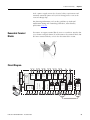
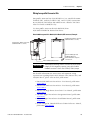
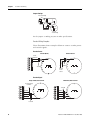
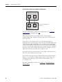
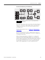
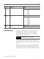
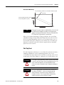
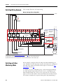
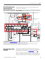
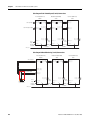
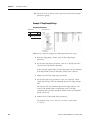
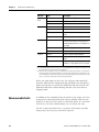
Removable Terminal
Blocks
To remove an upper terminal block, insert a screwdriver into the slot
(a) as shown and push down (b) to disconnect the terminal block. For
the lower terminal blocks, reverse the direction of the action.
a
b
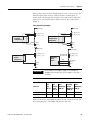
S52 S62
S72 S82
S32 S42
X32 X42
Pulse
Test
Outputs
Safe
Stop
(SS_In)
Safe
Limited
Speed
(SLS_In)
Enabling
Switch
(ESM_In)
Door
Monitor
(DM_In)
Lock
Monitor
(LM_In)
Publication 440R-UM004A-EN-P - December 2008
SLS_Out
(Cascade)
2 OSSD
2 OSSD
34
44
68
78
Lo
Y37
SS_Out
(Cascade)
Door Lock
Control
(DC_Out)
Bipolar
Hi
Y30 Y35
Fault_Status
Y33
SLS_Status
Y31 Y32
Diag.
Out
GND
Y2
SLS_Command
S34
Stop_Command
Y1
24V dc
DPI
Feedback
(RL_In)
Isolated Outputs
13
A1
51
52
Motion
Power
(MP_Out)
A2
Door Lock
Control
(DC_Out)
Cascade
2 OSSD
Hi
S12 S22
Hi
S11 S21
Reset_In
RJ45-1
Monitor
Encoder
PS
24V dc
Encoder 1
RJ45-2
Mini-DIN
HIM
Encoder 2
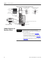
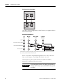
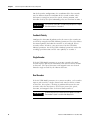
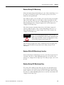
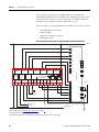
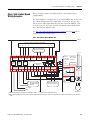
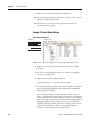
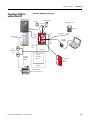
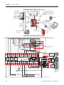
Circuit Diagram
24
51
52
14
33
Chapter 3
Installation and Wiring
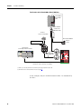
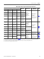
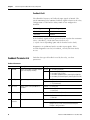
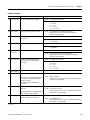
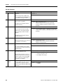
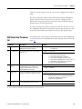
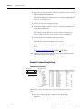
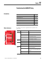
Terminal Connections
Tighten all terminal screws firmly and recheck them after all
connections have been made. Recommended terminal screw torque is
0.6…0.8 Nm (5…7 lb-in).
Terminal
Function
A1
+24V dc, user supply(1)
A2
Common, user supply
S11, S21
Test_Out_0, Test_Out_1, pulse test output for Safe Stop (SS), Safe Limited Speed (SLS), Enabling Switch Monitor (ESM),
Door Monitor (DM), and Lock Monitor (LM)
S12, S22
SS_In_Ch0, SS_In_Ch1, Safe Stop (SS) dual-channel input
S72, S82
ESM_In_Ch0, ESM_In_Ch1, Enabling Switch Monitoring (ESM) dual-channel input
S52, S62
SLS_In_Ch0, SLS_In_Ch1, Safe Limited Speed (SLS) dual-channel input
S32, S42
DM_In_Ch0, DM_In_Ch1, Door Monitoring (DM) dual-channel input
X32, X42
LM_In_Ch0, LM_In_Ch1, Lock Monitor (LM) dual-channel input, solenoid position
Y1
24V dc output; RL Feed for reset (S34) and for feedback (Y2)
S34
Reset_In
Y2
RL_In, feedback input
Y35
SLS_Status output
Y37
Fault_Status output
13
Supply power for SS safety output 14 and Motion Power (MP) safety output 24
14, 24
MP_Out_Ch0, MP_Out_Ch1, Motion Power (MP) outputs
68, 78
SLS_Out_Ch0, SLS_Out_Ch1, Safe Limited Speed (SLS) outputs
51
DC_Out_Ch0 (High Side), Door Control output (door switch solenoid, bipolar or 2 Channel Source)
52
DC_Out_Ch1 (Low Side), Door Control output (door switch solenoid, bipolar or 2 Channel Source)
34, 44
SS_Out_Ch0, SS_Out_Ch1, Safe Stop (SS) outputs
Y31
24V dc power for isolated outputs
Y32
Stop_Command, isolated output
Y33
SLS_Command, isolated output
Y30
GND for isolated outputs
(1) The MSR57P may be powered when +24V power is removed from terminal A1 and a sourcing safety output is shorted to +24V. If A1 power must be removed, also remove
any power that could be shorted to a safety sourcing output.
34
Publication 440R-UM004A-EN-P - December 2008
Installation and Wiring
Compatible Encoders
Chapter 3
These feedback devices are supported.
Supported Feedback Devices
Cat. No. and Description
842HR-xJxxx15FWYx
Sin/Cos Encoders(1)
Incremental
Encoders(1)
845T-xx12xxx-x and 845T-xx13xxx-x
845T-xx42xxx and 845T-xx43xxx-x
845T-xx52xxx and 845T-xx53xxx-x
845H-SJxxx4xxYxx
Additional Resources
Refer to the Bulletin 842HR Sin/Cosine Encoders product
profile, publication 842HR-PP001, for more information on
these encoders.
Refer to the Sensors Reference Catalog, publication C115,
for catalog number, dimensions, and specifications for
Bulletin 845T and 845H Incremental Encoders.
1326AB-Bxxxx-M2L/-S2L
HPK-Series Asynchronous Servo Motor
MP-Series Motors with embedded Sin/Cos or
incremental encoders
Refer to the Kinetix Motion Control Selection Guide,
publication GMC-SG001, for more information on these
motors.
TL-Series (TLY-Axxxxx-H) Motors with incremental
encoders
Rotary Motors
Any motor with SHS-170 Stegmann encoder
Any motor with SCS-60 Stegmann encoder
Any motor with SRS-60 Stegmann encoder
Any motor with SRM-60 Stegmann encoder
Refer to the product documentation for your specific
motor to determine the encoder type.
Any motor with SCS-Kit 101 Stegmann encoder
Any motor with SRS660 Stegmann encoder
Linear Actuators
MP-Series Integrated Linear Stages
Refer to the Kinetix Motion Control Selection Guide,
publication GMC-SG001, for more information on these
actuators.
(1) Maximum cable length for encoders is 90 m (295 ft).
Publication 440R-UM004A-EN-P - December 2008
35
Chapter 3
Installation and Wiring
Connect an Encoder
Use twisted-pair, individually-shielded cable to connect encoders and
drives. Refer to your encoder or drive manual for proper cable type
and maximum length.
IMPORTANT
IMPORTANT
ATTENTION
The drive or encoder and the MSR57P power supply reference
must be the same.
The MSR57P relay has an internal resistance of 600Ω on each
of the encoder signals to achieve an equivalent load resistance
of 100Ω if used with a drive that has 120Ω internal terminating
resistors. Your encoder may require that the equivalent load
resistance be 100Ω or greater. Refer to your encoder user
manual to make sure the equivalent termination resistance
does not exceed the encoder signal loading specification.
Do not use external terminating resistors with PowerFlex or
Kinetix drives. Doing so may cause permanent damage to the
drive.
The following illustrations show simple examples of how to connect
an MSR57P relay with an encoder, with or without a drive.
Single Encoder without a Drive
Encoder Power Supply (1)
1
9
Encoder 1
Sin/Cos or Incremental
Terminal Blocks
S32 S42 S52 S62
S11 S21 S12 S22
13 14
34 44
P
Encoder 1
24 A1
51 52
Config
Lock
PWR/Fault
DPI
Stop
Inputs
RJ45
Limited Speed
Standstill
Safe Speed
Status
Encoder Cable
1585J-M8RB-2M5
Motion Power Door
Encoder 2
S72 S82 X32 X42
Y31 Y32 Y33 Y30
Y1 Y2 S34 Y37
68 78 Y35 A2
(1) Refer to your encoder specifications to determine power supply requirements (5V, 9V, 12V, or 24V).
36
Publication 440R-UM004A-EN-P - December 2008
Installation and Wiring
Chapter 3
Two Encoders without a Drive
Encoder 1
Sin/Cos or
Incremental
Encoder Power Supply (1)
Terminal Blocks
Encoder 2
Sin/Cos or
Incremental
Encoder Power Supply (1)
Encoder Cables
1585J-M8RB-2M5
Terminal Blocks
(1) Refer to your encoder specifications to determine power supply requirements (5V, 9V, 12V, or 24V).
Single Encoder with PowerFlex Drive
PowerFlex Drive
Encoder 1
Incremental
(1)
Encoder Cable
1585J-M8RB-2M5
(1) Terminate shield to functional earth at drive end. See page 53.
Encoder power (5V or 12V) sourced from the drive.
Publication 440R-UM004A-EN-P - December 2008
37
Chapter 3
Installation and Wiring
Two Encoders with PowerFlex Drive
PowerFlex Drive
Encoder 1
Incremental
(2)
Encoder 2
Incremental
Encoder Power Supply(1)
Encoder Cables
1585J-M8RB-2M5
Terminal Blocks
(1) Refer to your encoder specifications to determine power supply requirements (5V, 9V, 12V, or 24V).
(2) Terminate shield to functional earth at drive end. See page 53.
Encoder power (5V or 12V) sourced from the drive.
38
Publication 440R-UM004A-EN-P - December 2008
Installation and Wiring
Chapter 3
Single Encoder with a Kinetix 6000 or Kinetix 7000 Drive
Kinetix 6000 or
Kinetix 7000
Drive
Logix Platform
(ControlLogix Controller Shown)
Motor Feedback
Connector Kit
2090-K6CK-D15M
(1)
Motor with Embedded
Encoder 1
Sin/Cos
Encoder Cable
1585J-M8RB-2M5
Customer-provided I/O cable for standard I/O
connections such as Start, Stop, SLS Request.
(1) Terminate shield to functional earth at drive end. See page 52.
Publication 440R-UM004A-EN-P - December 2008
39
Chapter 3
Installation and Wiring
Two Encoders with a Kinetix 6000 or Kinetix 7000 Drive
Kinetix 6000 or
Kinetix 7000
Drive
Motor Feedback
Connector Kit
2090-K6CK-D15M
Encoder 2
Sin/Cos or Incremental
(2)
Encoder Power Supply(1)
Motor with Embedded
Encoder 1
Sin/Cos
Logix Platform
(ControlLogix Controller Shown)
Encoder Cables
1585J-M8RB-2M5
Customer-provided I/O cable for standard I/O
connections such as Start, Stop, SLS Request
(1) Refer to your encoder specifications to determine power supply requirements (5V or 9V).
(2) Terminate shield to functional earth at drive end. See page 52.
In this example, only the feedback from Encoder 1 is monitored by
the drive.
40
Publication 440R-UM004A-EN-P - December 2008
Installation and Wiring
Chapter 3
Monitoring Feedback from Two Encoders with a Kinetix 6000 or Kinetix 7000 Drive
Kinetix 6000 or
Kinetix 7000
Drive
Motor Feedback
Connector Kit
2090-K6CK-D15M
Auxiliary Feedback
Connector Kit
2090-K6CK-D15F
(1)
Encoder Cables
1585J-M8RB-2M5
Encoder 2
Sin/Cos or Incremental
Motor with Embedded
Encoder 1
Sin/Cos
(1) Terminate shield to functional earth at drive end. See page 52.
In this example, feedback from both encoders is monitored by the
drive.
Publication 440R-UM004A-EN-P - December 2008
41
Chapter 3
Installation and Wiring
Encoder Cable
Specifications
To connect the MSR57P, use the 1585J-M8RB-2M5 cable available from
Rockwell Automation.
1585J-M8RB-2M5 Cable
2.5 m Cable
Catalog Number
Connection to
MSR57P Relay
Connection to
Encoder
Connection to Drive
or Power Supply
1585J-M8RB-2M5
RJ45
Flying leads
Flying leads
1585J-M8RB-2M5 Flying-Lead Wires
Pin Number
Wire Color
Signal
1
White/Orange
GND
2
Orange
Vcc
3
White/Blue
A1-/SIN1-REF
4
Blue
A1+/SIN1+
5
Green
NC
6
White/Brown
B1-/COS1-REF
7
White/Green
NC
8
Brown
B1+/COS1+
9
Bare
Shield (case)(1)
(1) Terminate encoder shield to functional earth at the drive.
Feedback Cable
Connections for Kinetix
2000, Kinetix 6000, Kinetix
7000 and Ultra3000 Drives
Connection Option
Low-profile connectors for
Kinetix 6000 and
Kinetix 7000 Drives
Low-profile connectors for
Kinetix 2000 Drives
Flying lead cable at
Ultra3000 drive end with
one of these three kits.
42
To connect your MSR57P relay to a Kinetix drive, review the
connector options and compatible cable and motor types listed in the
following tables.
Connector Options for Connecting Motor and Auxiliary Feedback
Connector Kit
Catalog Number
Description
Using this Type of Cable
2090-K6CK-D15M
Motor feedback connector kit
2090-UXBK-D15xx
15-pin panel-mounted breakout board kit
Refer to the table of Motor Feedback Cables for
Specific Motor/Feedback Combinations.
2090-K6CK-D15F
Auxiliary feedback connector kit
User-supplied flying-lead cable.
2090-K2CK-D15M
Motor feedback connector kit
2090-K2CK-COMBO
Motor, auxiliary, and I/O feedback connector kit
2090-UXBK-D15xx
15-pin panel-mounted breakout board kit
2090-UXBB-DM15
15-pin drive-mounted breakout board
2090-UXBK-D15xx
15-pin panel-mounted breakout board kit
2090-UXCK-D15
15-pin (high-density D-shell) drive connector kit
Refer to the table of Motor Feedback Cables for
Specific Motor/Feedback Combinations.
Refer to the table of Motor Feedback Cables for
Specific Motor/Feedback Combinations.
Publication 440R-UM004A-EN-P - December 2008
Installation and Wiring
Chapter 3
Motor Feedback Cables for Specific Motor/Feedback Combinations
Compatible Drives(1)
Motor Series
Ultra3000
Kinetix 2000
Kinetix 6000
Kinetix 7000
2098-DSD-xxx
2093-AC05-MPx
2093-AMxx
2094-ACxx-Mxx-S
2094-AMxx-S
—
MPL-Axxxx-M/S
2098-DSD-HVxxx
—
2094-BCxx-Mxx-S
2094-BMxx-S
—
MPL-Bxxxx-M/S
—
2094-BCxx-Mxx-S
2094-BMxx-S
—
1326AB-Bxxxx-M2L
1326AB-Bxxxx-S2L
2098-DSD-HVxxx
MPL-B5xxx-M/S,
MPL-B6xxx-M/S,
MPL-B8xxx-M/S,
MPL-B9xxx-M/S
Feedback Type
Multi-turn
high-resolution
absolute or
single-turn
high-resolution
encoder
Flying-Lead
Feedback Cable
Pinout
2090-XXxFMP-Sxx(2) (3)
or
2090-XXNFMF-Sxx
(non-flex)(4)
or
2090-CFBM4DF-CDAFxx
(continuous-flex)(4)
Page 44
2090-XXNFMF-Sxx
(non-flex)(4)
or
2090-CFBM4DF-CDAFxx
(continuous-flex)(4)
Page 47
Page 49
—
—
—
2099-BMxx-S
2098-DSD-xxx
2093-AC05-MPx
2093-AMxx
2094-ACxx-Mxx-S
2094-AMxx-S
—
MPL-A3xxx-H
MPL-A4xxx-H
MPL-A45xxx-H
2098-DSD-xxx
2093-AC05-MPx
2093-AMxx
2094-ACxx-Mxx-S
2094-AMxx-S
—
MPL-Axxxx-V/E
MPF-Axxxx-M/S
MPS-Axxxx-M/S
2098-DSD-HVxxx
—
2094-BCxx-Mxx-S
2094-BMxx-S
—
MPL-Bxxxx-V/E
MPF-Bxxxx-M/S
MPS-Bxxxx-M/S
2098-DSD-xxx
2093-AC05-MPx
2093-AMxx
2094-ACxx-Mxx-S
2094-AMxx-S
—
MPL-A15xxx-H
MPL-A2xxx-H
2098-DSD-HVxxx
—
2094-BCxx-Mxx-S
2094-BMxx-S
—
MPL-B15xxx-H
MPL-B2xxx-H
—
—
—
2099-BMxx-S
HPK-series
High-resolution
encoder
2098-DSD-xxx
2093-AC05-MPx
2093-AMxx
2094-ACxx-Mxx-S
2094-AMxx-S
—
TLY-Axxxx-H
Incremental encoder
2090CFBM6DF-CBAAxx
Page 50
2098-DSD-xxx
2093-AC05-MPx
2093-AMxx
2094-ACxx-Mxx-S
2094-AMxx-S
—
MPAS-Axxxx-V/A
—
2094-BCxx-Mxx-S
2094-BMxx-S
Multi-turn
high-resolution
absolute or
single-turn
high-resolution
encoder
2090-XXNFMF-Sxx
(non-flex)(4)
or
2090-CFBM4DF-CDAFxx
(continuous-flex)(4)
Page 47
Page 49
2098-DSD-HVxxx
(1)
(2)
(3)
(4)
—
MPAS-Bxxxx-V/A
Incremental encoder
Multi-turn
high-resolution
absolute or
single-turn
high-resolution
encoder
Incremental encoder
Refer to the Kinetix Motion Control Selection Guide, publication GMC-SG001 for detailed information on the compatibility of specific drive and motor combinations.
For Bulletin MPL motors equipped with bayonet-style connectors.
These cables are available as non-flex (catalog number 2090-XXNFMP-Sxx) and continuous-flex (catalog number 2090-XXTFMP-Sxx).
For Bulletin MPL motors equipped with DIN-style connectors.
Publication 440R-UM004A-EN-P - December 2008
43
Chapter 3
Installation and Wiring
Flying-lead Feedback Cable Pin-outs
Motors Using 2090-XXxFMP-Sxx Feedback Cable
MPL-Bxxx-M/-S, MPL-A5xxx-M/-S, and 1326AB-Bxxx-M2L/-S2L Motors
Drive Side
Motor Connector
Pin(1)
Signal
MSR57P Relay Side
1585J-M8RB-2M5 Cable
Drive MF
Connector Pin
Pin
Wire Color
Signal
A
Black
Sine+
1
—>
4
Blue
A1+/SIN1+
B
White/Black
Sine-
2
—>
3
White/Blue
A1-/SIN1-REF
C
Red
Cos+
3
—>
8
Brown
B1+/COS1+
D
White/Red
Cos-
4
—>
6
White/Brown
B1-/COS1-REF
E
Green
Data+
5
NC
F
White/Green
Data-
10
NC
K
Gray
EPWR_5V
14
NC
L
White/Gray
ECOM
6
—>
1
White/Orange
GND
N
Orange
EPWR_9V
7
—>
2
Orange
Vcc
R
TS+
11
NC
T
S1
12
NC
U
S2
13
NC
V
S3
8
NC
5
Green
NC
7
White/Green
NC
Bare
Shield (case)
9(2)
(1) Bayonet-style connector
(2) Make sure you ground the shield properly to the low profile connector along with the feedback cable. See the
diagram on page 52.
44
Publication 440R-UM004A-EN-P - December 2008
Installation and Wiring
Chapter 3
MPL-A3xxx-M/-S, MPL-A4xxx-M/-S, and MPL-A45xxx-M/-S Motors
Drive Side
Motor Connector
Pin(1)
Signal
MSR57P Relay Side
1585J-M8RB-2M5 Cable
Drive MF
Connector Pin
Pin
Wire Color
Signal
A
Black
Sine+
1
—>
4
Blue
A1+/SIN1+
B
White/Black
Sine-
2
—>
3
White/Blue
A1-/SIN1-REF
C
Red
Cos+
3
—>
8
Brown
B1+/COS1+
D
White/Red
Cos-
4
—>
6
White/Brown
B1-/COS1-REF
E
Green
Data+
5
NC
F
White/Green
Data-
10
NC
K
Gray
EPWR_5V
14
—>
2
Orange
Vcc
L
White/Gray
ECOM
6
—>
1
White/Orange
GND
N
Orange
EPWR_9V
7
NC
R
TS+
11
NC
T
S1
12
NC
U
S2
13
NC
V
S3
8
NC
5
Green
NC
7
White/Green
NC
Bare
Shield (case)
9(2)
(1) Bayonet-style connector
(2) Make sure you ground the shield properly to the low profile connector along with the feedback cable. See the
diagram on page 52.
Publication 440R-UM004A-EN-P - December 2008
45
Chapter 3
Installation and Wiring
MPL-A3xxx-H, MPL-A4xxx-H, and MPL-A45xxx-H Motors
Drive Side
Motor Connector
Pin(1)
Signal
MSR57P Relay Side
1585J-M8RB-2M5 Cable
Drive MF
Connector Pin
Pin
Wire Color
Signal
A
Black
AM+
1
—>
4
Blue
A1+/SIN1+
B
White/Black
AM-
2
—>
3
White/Blue
A1-/SIN1-REF
C
Red
BM+
3
—>
8
Brown
B1+/COS1+
D
White/Red
BM-
4
—>
6
White/Brown
B1-/COS1-REF
E
Green
IM+
5
NC
F
White/Green
IM-
10
NC
K
Gray
EPWR_5V
14
—>
2
Orange
Vcc
L
White/Gray
ECOM
6
—>
1
White/Orange GND
N
Orange
EPWR_9V
7
NC
R
TS+
11
NC
T
S1
12
NC
U
S2
13
NC
V
S3
8
NC
5
Green
NC
7
White/Green
NC
Bare
Shield (case)
9(2)
(1) ITT Cannon connector
(2) Make sure you ground the shield properly to the low profile connector along with the feedback cable. See the
diagram on page 52.
46
Publication 440R-UM004A-EN-P - December 2008
Installation and Wiring
Chapter 3
Motors Using 2090-XXNFMF-Sxx or 2090-CFBM4DF-CDAFxx Feedback Cable
MPL-B15xxx-V/-E, MPL-B2xxx-V/-E, MPF/MPS-Bxxx-M/-S, MPF-A5xx-M/-S
Motors and MPAS-Bxxxx-VxxSxA Linear Stages
Drive Side
Motor Connector
Pin (1)
Signal
MSR57P Relay Side
1585J-M8RB-2M5 Cable
Drive MF
Connector Pin
Pin
Wire Color
Signal
1
Black
Sine+
1
—>
4
Blue
A1+/SIN1+
2
White/Black
Sine-
2
—>
3
White/Blue
A1-/SIN1-REF
3
Red
Cos+
3
—>
8
Brown
B1+/COS1+
4
White/Red
Cos-
4
—>
6
White/Brown
B1-/COS1-REF
5
Green
Data+
5
NC
6
White/Green Data-
10
NC
9
Gray
EPWR_5V
14
NC
10
White/Gray
ECOM
6
—>
1
White/Orange
GND
11
Orange
EPWR_9V
7
—>
2
Orange
Vcc
13
TS+
11
NC
15
S1
12
NC
16
S2
13
NC
17
S3
8
NC
5
Green
NC
7
White/Green
NC
9(2) Bare
Shield (case)
(1) DIN Connector
(2) Make sure you ground the shield properly to the low profile connector along with the feedback cable. See the
diagram on page 52.
Publication 440R-UM004A-EN-P - December 2008
47
Chapter 3
Installation and Wiring
MPL-A15xxx-V/-E, MPL-A2xxx-V/-E, MPF/MPS-A3xx-M/-S, MPF/MPS-A4xx-M/-S,
MPF/MPS-A45xx-M/-S, MPS-A5xx-M/-S Motors and MPAS-Axxxx-VxxSxA Linear
Stages
Drive Side
Motor Connector Pin
Signal
(DIN Connector)
MSR57P Relay Side
1585J-M8RB-2M5 Cable
Drive MF
Connector Pin
Pin
Wire Color
Signal
1
Black
Sine+
1
—>
4
Blue
A1+/SIN1+
2
White/Black
Sine-
2
—>
3
White/Blue
A1-/SIN1-REF
3
Red
Cos+
3
—>
8
Brown
B1+/COS1+
4
White/Red
Cos-
4
—>
6
White/Brown
B1-/COS1-REF
5
Green
Data+
5
NC
6
White/Green
Data-
10
NC
9
Gray
EPWR_5V
14
—>
2
Orange
Vcc
10 White/Gray
ECOM
6
—>
1
White/Orange
GND
11 Orange
EPWR_9V
7
NC
13
TS+
11
NC
15
S1
12
NC
16
S2
13
NC
17
S3
8
NC
5
Green
NC
7
White/Green
NC
Bare
Shield (case)
9(1)
(1) Make sure you ground the shield properly to the low profile connector along with the feedback cable. See the
diagram on page 52.
48
Publication 440R-UM004A-EN-P - December 2008
Installation and Wiring
Chapter 3
MPL-A15xxx-H, MPL-A2xxx-H, MPL-B15xxx-H, MPL-B2xxx-H Motors and
MPAS-A/Bxxxx-ALMx2C Linear Stages
Drive Side
MSR57P Relay Side
Motor Connector
Pin (DIN
Connector)
Signal
1
Black
AM+
1
—>
2
White/Black
AM-
2
3
Red
BM+
4
White/Red
5
1585J-M8RB-2M5 Cable
Drive MF
Connector Pin
Pin
Wire Color
Signal
4
Blue
A1+/SIN1+
—>
3
White/Blue
A1-/SIN1-REF
3
—>
8
Brown
B1+/COS1+
BM-
4
—>
6
White/Brown
B1-/COS1-REF
Green
IM+
5
NC
6
White/Green
IM-
10
NC
9
Gray
EPWR_5V
14
—>
2
Orange
Vcc
10 White/Gray
ECOM
6
—>
1
White/Orange
GND
11 Orange
EPWR_9V
7
NC
13
TS+
11
NC
15
S1
12
NC
16
S2
13
NC
17
S3
8
NC
5
Green
NC
7
White/Green
NC
Bare
Shield (case)
9(1)
(1) Make sure you ground the shield properly to the low profile connector along with the feedback cable. See the
diagram on page 52.
Publication 440R-UM004A-EN-P - December 2008
49
Chapter 3
Installation and Wiring
Motors Using 2090-CFBM6DF-CBAAxx Cables
TLY-Axxxx-H Motors
Drive Side
MSR57P Relay Side
Drive CN2
Connector
Pin
1585J-M8RB-2M5 Cable
Motor Connector
Pin
Signal
9
Black
AM+
1
—>
10
White/Black
AM-
2
11
Red
BM+
12
White/Red
13
Pin
Wire Color
Signal
4
Blue
A1+/SIN1+
—>
3
White/Blue
A1-/SIN1-REF
3
—>
8
Brown
B1+/COS1+
BM-
4
—>
6
White/Brown
B1-/COS1-REF
Green
IM+
5
NC
14
White/Green
IM-
10
NC
22
Gray
EPWR_5V
14
—>
2
Orange
Vcc
23
White/Gray
ECOM
6
—>
1
White/Orange
GND
15
S1
12
NC
17
S2
13
NC
19
S3
8
NC
24
Shield
White/Orange
GND
5
Green
NC
7
White/Green
NC
Bare
Shield (case)
—>
1
NC
NC
NC
9(1)
(1) Make sure you ground the shield properly to the low profile connector along with the feedback cable. See the
diagram on page 52.
50
Publication 440R-UM004A-EN-P - December 2008
Installation and Wiring
Chapter 3
Wiring Low-profile Connector Kits
Low-profile connector kits (2090-K6CK-Dxxx) are suitable for motor
feedback (MF), auxiliary feedback (AF), and I/O (IOD) connections
on any Kinetix 6000 IAM or AM module or on a Kinetix 7000 Drive
when used with an MSR57P relay.
Use Low-profile connector kit 2090-K2CK-D15M or
2090-K2CK-COMBO for Kinetix 2000 drives.
Kinetix 6000 Integrated Axis Module/Axis Module (MF connector) Example
Integrated Axis Module, Side View
(2094-BC02-M02-S is shown)
Integrated Axis Module, Front View
(2094-BC02-M02-S is shown)
Motor Feedback (MF) Connector
IMPORTANT
Bulletin 2090 (flying lead)
Feedback Cable with
K6CK-DM15Mxx Low-profile
Connector Kit
Tightening the mounting screws is essential to ensure shield
integrity of the low-profile connector covers with the drive
feedback connector D-shells. Use 0.4 Nm (3.5 lb-in) torque.
For detailed information on connections and important wiring
requirements regarding Kinetix 2000, Kinetix 6000, Kinetix 7000, and
Ultra3000 drives, please refer to these publications:
• Kinetix 2000 Multi-axis Servo Drive User Manual, publication
2093-UM001.
• Kinetix 6000 Multi-axis Servo Drive User Manual, publication
2094-UM001.
• Kinetix 7000 High Power Servo Drive User Manual, publication
2099-UM001.
• Ultra3000 Digital Servo Drives Integration Manual, publication
2098-IN005.
• Ultra3000 Digital Servo Drives Installation Manual, publication
2098-IN003.
• System Design for Control of Electrical Noise Reference Manual,
publication GMC-RM001.
Publication 440R-UM004A-EN-P - December 2008
51
Chapter 3
Installation and Wiring
Wiring (15-Pin) Flying-lead Feedback Cable Connections
15-pin (male) Motor Feedback
Low-profile Connector
Bare Wires
Wire Insulation
Foil Shield
Mounting
Screws
Bulletin 2090
Cable
Tie Wrap
Shield Clamp
Exposed Braid under clamp
Turn clamp over to hold
small wires secure.
Pin 1
0 15 14 13 12 11 10 9 8 7 6 5 4 3 2 1
Braided Shield
Outer Insulation
Pin 10
Pin 5
Bulletin 2090 Feedback Cable
Feedback Connections for
PowerFlex 70 Drives
IMPORTANT
15-pin (female) Auxiliary Feedback
Low-profile Connector
Pin 15
Pin 1
Pin 11
Pin 6
Pin 5
Pin 10
Pin 6
Pin 11
Pin 15
Secure exposed shield under clamp for proper
grounding.
1585J-M8RB-2M5 Cable
For detailed information in installing and connecting
PowerFlex 70 drives, including important wiring requirements,
refer to these publications:
• PowerFlex 70 User Manual, publication 20A-UM001.
• DriveGuard Safe-Off Option (Series B) for PowerFlex 40P
and 70 AC Drives User Manual, publication PFLEX-UM003.
• Wiring and Grounding Guidelines for AC Drives, publication
DRIVES-IN001.
52
Publication 440R-UM004A-EN-P - December 2008
Installation and Wiring
Chapter 3
Safe Off Board Terminal Block (Enhanced Control Only)
4 3 2 1
No. Signal
Description
1
Monitor - N.C.
2
Common - N.C.
Normally closed contacts for monitoring relay status.
Maximum Resistive Load: 250V ac / 30V dc / 50 VA / 60 W
Maximum Inductive Load: 250V ac / 30V dc / 25 VA / 30 W
3
+24V dc
4
24V Common
Connections for user supplied power to energize coil.
Encoder Interface Terminal Block (Enhanced Control Only)
1
6
PowerFlex 70 Side
Terminal
Signal
1
5-12V Power(1)
2
3
4
5
6
CASE
Power Return
Encoder B (NOT)
Encoder B
Encoder A (NOT)
Encoder A
Shield
Pin
—> 2
—>
—>
—>
—>
—>
1
6
8
3
4
—> 9
MSR57P Relay Side
Color
Signal
Orange
Vcc
White/Orange
White/Brown
Brown
White/Blue
Blue
Bare
GND
B1-/COS1B1+/COS1+
A1-/SIN1A1+/SIN1+
Shield
(1) Jumper selectable +5/12V is available on 20A-ENC-1 Encoder Boards.
Publication 440R-UM004A-EN-P - December 2008
53
Chapter 3
Installation and Wiring
Jumper Settings
Receive Voltage
= 12V
= 5V
= 12V
= 5V
Send Voltage
Set the jumper according to your encoder specifications.
Encoder Wiring Examples
These illustrations show examples of how to connect encoder power
and encoder signals.
Encoder Power
Internal (Drive)
External Source
12V dc
(250 mA)
1
2
3
4
5
6
Common
Common
+
To
Shield
To
Shield
External
Power
Source
Encoder Signal
Single-ended, Dual-channel
Differential, Dual-channel
To Power Supply
Common
1
2
3
4
5
6
1
2
B (NOT)
B
3
4
5
6
A (NOT)
A
To Shield
B (NOT)
B
A (NOT)
A
To Shield
54
Publication 440R-UM004A-EN-P - December 2008
Installation and Wiring
Feedback Connections for
PowerFlex 700S Drives
Use the terminal connection information in the table to connect your
MSR57P relay to a PowerFlex 700S drive.
PowerFlex 700S Side
Terminal Signal
12
11
10
9
8
7
6
5
4
3
2
1
IMPORTANT
Connect a Configuration
Device
Chapter 3
Power Common
POWER
REFSIN
+SIN
REFCOS
+COS
Shield
Shield
NC
NC
DATA+ (RS 485)
DATA- (RS 485)
—>
—>
—>
—>
—>
—>
—>
Pin
MSR57P Relay Side
Color
Signal
1
2
3
4
6
8
9
White/Orange
Orange
White/Blue
Blue
White/Brown
Brown
Bare
GND
Vcc
A1-/SIN1A1+/SIN1+
B1-/COS1B1+/COS1+
Shield
NC
NC
NC
NC
For detailed information in installing and connecting
PowerFlex 700S drives, including important wiring
requirements, refer to the PowerFlex 700S Phase II Drive User
Manual, publication 20D-UM006.
If you are using a HIM to configure the relay, see Appendix C for
information on connecting a HIM and setting parameters with the
keypad.
If you are using software to configure the relay, see Appendix D for
information on connecting to a personal computer and using the
software.
Publication 440R-UM004A-EN-P - December 2008
55
Chapter 3
56
Installation and Wiring
Publication 440R-UM004A-EN-P - December 2008
Chapter
4
Speed Monitoring I/O Signals
Introduction
Inputs
This chapter describes the input and output signals of the speed
monitoring relay.
Topic
Page
Inputs
57
Outputs
63
The MSR57P relay has five inputs capable of safety-certified
dual-channel support. Each dual-channel input supports a specific
safety function of the MSR57P relay: Safe Stop, Safe Limited Speed,
Door Monitoring, Enabling Switch Monitoring, and Lock Monitoring.
All five inputs are electrically identical and rely on the same pair of
pulse test outputs, Test_Out_0 (S11) and Test_Out_1 (S21), when not
using the OSSD configuration.
The inputs can be configured for one of the following settings:
•
•
•
•
•
•
•
0
1
2
3
4
5
6
=
=
=
=
=
=
=
Not used
Dual-channel equivalent (2NC)
Dual-channel equivalent 3 s (2NC 3s)
Dual-channel complementary (1NC + 1NO)
Dual-channel complementary 3 s (1NC + 1NO 3s)
Dual-channel SS equivalent 3 s (2 OSSD 3s)
Single channel (1NC).
IMPORTANT
Single-channel configuration (1NC) is not SIL CL3, PL(e), Cat 4.
When configured for dual-channel operation, the consistency between
the two channels is evaluated. For dual-channel equivalent
configurations, the active state for both channel 0 and channel 1 is
ON. For dual-channel complementary configurations, the active state
for channel 0 is ON and the active state for channel 1 is OFF. Any time
both channels are not active, the input pair is evaluated as OFF.
57Publication 440R-UM004A-EN-P - December 2008
57
Chapter 4
Speed Monitoring I/O Signals
When both channels are active, if one channel’s input terminal
transitions from active to inactive and back to active, while the other
channel’s input terminal remains active, both channel must go inactive
at the same time before the evaluated status may return to ON. This
condition is called ‘cycle inputs required’.
cycle inputs required
Channel 0 active
in active
Channel 1
active
in active
Evaluated Status
ON
OFF
If inputs are configured with the following dual channel settings, an
Input fault occurs if the inputs are discrepant for longer than 3
seconds or if a ‘cycle inputs required’ condition exists lor longer than
3 seconds.
• 2 = Dual-channel equivalent 3 s (2NC 3s)
• 4 = Dual-channel complementary 3 s (1NC + 1NO 3s)
• 5 = Dual-channel SS equivalent 3 s (2 OSSD 3s)
If inputs are configured with one of the following dual channel
settings, which have no limit on the length of time that inputs can be
discrepant, an Input fault will not occur for any discrepant condition
or for any ‘cycle inputs required’ condition.
• 1 = Dual-channel equivalent (2NC)
• 3 = Dual-channel complementary (1NC + 1NO)
For all input settings except Dual-channel SS equivalent 3 s
(2 OSSD 3s), if one or two channels are connected to a 24V DC source
other than terminals S11 and S21, a fault occurs.
I/O faults are Stop Category Faults, which initiate the configured Safe
Stop Type. I/O faults are latched until the relay is successfully reset.
For more information on I/O faults, see Chapter 12, Troubleshoot the
MSR57P Relay.
58
Publication 440R-UM004A-EN-P - December 2008
Speed Monitoring I/O Signals
Chapter 4
When using a dual-channel complementary (1NC + 1NO) device, the
normally-open input must be connected to the second input, as
shown in the illustration. For example, if the door is open when the
input is ON, the normally-open contact must be the second input
(Input 1).
Safety Input Wiring Examples
MSR57P Relay
MSR57P Relay
Test_Out_0 (S11)
Test_Out_1 (S21)
Test_Out_0 (S11)
Test_Out_1 (S21)
Dual-channel
Equivalent
Safety Device
Dual-channel
Complementary
Safety Device
Input 0
Input 1
Input 0
Input 1
MSR57P Relay
Single
Channel
Safety Device
MSR57P Relay
Test_Out_0 (S11)
Test_Out_1 (S21)
Solid State
Safety
Device
Input 0
Input 1
IMPORTANT
Not Connected
Not Connected
GND
OSSD1
OSSD2
Test_Out_0 (S11)
Test_Out_1 (S21)
A2, Common
Input 0
Input 1
Cross-wiring of Test Outputs to Inputs is not allowed. For
example, do not connect Test_Out_0 to Input 1 or Test_Out_1
to Input 0.
Terminals
Function
Safe
Stop
(SS_In)
Safe
Limited
Speed
(SLS_In)
Door
Monitoring
(DM_In)
Lock
Enabling
Monitoring
Switch
Monitoring (LM_In)
(ESM_In)
Input 0 = Channel 0
S12
S52
S32
S72
X32
Input 1 = Channel 1
S22
S62
S42
S82
X42
Short-circuits of the input loop to ground or 24V will be detected. For
dual-channel inputs, cross loops will also be detected.
Publication 440R-UM004A-EN-P - December 2008
59
Chapter 4
Speed Monitoring I/O Signals
Safe Stop Input (SS_In)
The SS_In input is intended for connection to an E-Stop device.
The SS_In input must be active to initiate Safe Stop monitoring. If the
SS_In input is being monitored, a transition from ON to OFF (closed
to open) is used to request the configured Safe Stop Type.
In a cascaded configuration, the SS_In input is connected to the Safe
Stop (SS_Out) output of an upstream MSR57P relay.
Safe Limited Speed Input (SLS_In)
The SLS_In input is used to connect to a switch whose OFF state
requests Safe Limited Speed monitoring.
If Safe Limited Speed monitoring is configured, the SLS_In input is
monitored from the time of a successful Safe Stop Reset or Safe
Limited Speed Reset, until the time that the configured Safe Stop Type
is initiated or the Safe State is entered.
If the SLS_In input is being monitored, the OFF state is used to request
the Safe Limited Speed monitoring functionality of the relay.
In a cascaded configuration, the SLS_In input is connected to the Safe
Stop (SS_Out) output of an upstream MSR57P relay.
Door Monitor Input (DM_In)
This input monitors the status of the door to indicate if it is open or
closed. The DM_In input can be connected to a non-guardlocking
switch if the door does not need to be locked. The door status is
monitored by the first unit in multi-axis systems.
The DM_In input is intended for connection to a guardlocking switch
when the speed monitoring relay is configured as a master device
with door monitoring. When the MSR57P relay is configured as a slave
in a cascaded system, its DM_In input is connected to the Door
Control output (DC_Out) of the upstream MSR57P relay.
60
Publication 440R-UM004A-EN-P - December 2008
Speed Monitoring I/O Signals
Chapter 4
Enabling Switch Monitor Input (ESM_In)
The ESM_In input is intended to be connected to an enabling switch.
The speed monitoring relay uses the ESM_In input as a safety enable
only, not for control. The ESM_In inputs function and monitoring is
performed by the first unit in multi-axis systems.
The ESM_In input ON state is used to enable motion under
mode-specific conditions in the Safety Limited Speed with Enabling
Switch (Lim Speed ES) and Safe Limited Speed with Door Monitoring
and Enabling Switch Monitoring (LimSpd DM ES) modes.
See Safe Limited Speed with Enabling Switch Monitoring Mode on
page 112 and Safe Limited Speed with Door Monitoring and Enabling
Switch Monitoring Mode on page 115 for the conditions that must be
true to start monitoring the ESM_In input.
If the ESM_In input is OFF while it is being monitored, an ESM
Monitoring Fault (Stop Category Fault) occurs and the relay initiates
the configured Safe Stop Type.
See Chapter 12, Troubleshoot the MSR57P Relay, for information on
faults and how to recover from them.
Lock Monitor Input (LM_In)
The LM_In input verifies that the guardlocking solenoid switch is
locked. It is intended to confirm the door control function.
The LM_In input is monitored by the first unit in multi-axis systems.
Publication 440R-UM004A-EN-P - December 2008
61
Chapter 4
Speed Monitoring I/O Signals
Reset Input (Reset_In)
The Reset input is for reset and monitoring of the safety circuit. The
reset input can be configured for automatic, manual, or manual
monitored reset types.
Wire the S34 reset input terminal to the 24V DC output terminal, Y1,
depending on the configured reset type, as shown.
Reset
Y1
Manual
S34
Reset_In
Reset
Y1
Manual
Monitored
S34
Reset_In
IMPORTANT
62
If you configure the relay for automatic reset, wiring of the S34
reset input terminal is not required.
Publication 440R-UM004A-EN-P - December 2008
Speed Monitoring I/O Signals
Chapter 4
Reset Loop Input (RL_In)
The RL_In input is used to monitor the normally-closed contacts of the
contactors that are used to remove power or to the feedback contacts
from a drive Safe-off circuit. The signal level of the RL_In may be used
to qualify a successful reset of the speed monitoring relay. For
feedback loop or external device monitoring and reset qualification,
wire the reset loop input, Y2 to the 24V dc output terminal Y1, as
shown.
Y1
Y2
RL_In
Outputs
The MSR57P relay has four safety control outputs and four diagnostic
outputs. The outputs have various output current capabilities,
depending on function.
See the specifications in Appendix A to verify your power
requirements.
Safety Control Outputs
Safe Stop Output (SS_Out)
The safe state for this signal is OFF.
These outputs are typically used in multi-axis applications. In
multi-axis applications, you can use these outputs to daisy-chain the
master to a slave device.
For SS_Out to SS_In cascaded signals, the interface is a dual-channel
sourcing solid state safety output connected to a dual-channel safety
input configured as OSSD. The outputs are pulse-tested when the P72
[SS Out Mode] parameter is configured for pulse-testing.
IMPORTANT
Publication 440R-UM004A-EN-P - December 2008
If you disable pulse-testing on this output, the achievable SIL,
Category, and PL ratings of your entire MSR57P safety system
are reduced.
63
Chapter 4
Speed Monitoring I/O Signals
SS_Out to SS_In Connections for Multi-axis Applications
MSR57P Master
SS_Out_Ch0
SS_Out_Ch1
34
44
S12
S22
SS_In_Ch0
SS_In_Ch1
S12 and S22 are configured as 2
OSSD inputs.
MSR57P Slave
For more information on multi-axis configurations, see Cascaded
Configurations starting on page 125.
Alternately, the first SS_Out output may be used to signal a
programmable logic controller (PLC) or a drive that a Safe Stop has
been requested.
If the SS_In is ON (closed) and a successful Safe Stop Reset is
performed, the SS_Out output is turned ON. If Lock Monitoring is not
enabled or the door control logic state is Unlock, the SS_Out signal
turns ON immediately when the SS_In turns ON. If Lock Monitoring is
enabled, and the door control logic state is Lock, the SS_Out signal is
not turned ON until the door has been locked by using the DC_Out
signal and the LM_In input has been verified as ON.
If the Safe Stop Type is initiated or if a Safe Stop is initiated due to a
fault, the SS_Out output is turned OFF.
If an error is detected on either channel of the dual-channel output, a
fault occurs. I/O faults are Stop Category Faults, which initiate the
configured Safe Stop Type. The fault is latched until the relay is
successfully reset.
For more information on faults, see Chapter 12, Troubleshoot the
MSR57P Relay.
64
Publication 440R-UM004A-EN-P - December 2008
Speed Monitoring I/O Signals
Chapter 4
Safe Limited Speed Output (SLS_Out)
The safe state for this signal in all cases is OFF.
The SLS_Out output functionality is determined by the configured
Safety Mode. If the SLS_In is ON and a successful Safe Stop or Safe
Limited Speed reset is performed, the SLS_Out turns ON in all Safe
Limited Speed modes except Safe Limited Speed Status Only.
For the Safe Limited Speed modes (SLS), the SLS_Out is used to
interconnect speed monitoring relays in multi-axis applications. For
SLS_Out to SLS_In cascaded signals, the interface is a dual-channel
sourcing solid state safety output connected to a dual-channel safety
input configured as OSSD. The outputs are pulse-tested when the P73
[SLS Out Mode] parameter is configured for pulse-testing.
IMPORTANT
If you disable pulse-testing on this output, the achievable SIL,
Category, and PL ratings of your entire MSR57P safety system
are reduced.
For a single unit system or the last unit in a cascaded system, the
SLS_Out is intended to be connected to an input of a safety
programmable logic controller (PLC). The same PLC could also control
the Safe Stop function with a safe PLC output connected to the Safe
Stop input (SS_In).
For the first or middle units in a cascaded system, the SLS_Out is
intended to be connected to the Safe Limited Speed input (SLS_In) of
the next relay in the cascaded system. This lets one SLS switch enable
Safe Limited Speed on all axes at the same time.
SLS_Out to SLS_In Connections for Multi-axis Applications
MSR57P Master
SLS_Out_Ch0
SLS_Out_Ch1
68
78
S52
S62
SLS_In_Ch0
SLS_In_Ch1
MSR57P Slave
Publication 440R-UM004A-EN-P - December 2008
65
Chapter 4
Speed Monitoring I/O Signals
For more information on multi-axis configurations, see Cascaded
Configurations starting on page 125.
For Safe Limited Speed Status Only modes, the SLS_Out output is used
as an indication that the Safe Limited Speed monitoring is active and
the monitored speed is less than the configured Safe Speed Limit. If
the speed is greater than or equal to the Safe Speed Limit, the SLS_Out
is turned OFF. When Safe Limited Speed monitoring is not active or
the relay is in a SLS Monitoring Delay [LimSpd Mon Delay], the
SLS_Out output is OFF. The SLS_Out output is turned OFF when a
Safe Stop has been initiated, a fault has occurred, or the relay is in the
safe state.
See the Safe Limited Speed Status Only Mode on page 119 for more
information.
If an error is detected on either channel of the dual-channel output, a
fault occurs. I/O faults are Stop Category Faults, which initiate the
configured Safe Stop Type. The fault is latched until the relay is
successfully reset.
For more information on faults, see Chapter 12, Troubleshoot the
MSR57P Relay.
Door Control Output (DC_Out)
You can use this output for door control in single-device and
multi-axis systems. This output attempts to maintain last state when a
fault occurs. When no faults are present, it can be used in
combination with the fault status as a standard status indication to a
programmable controller to identify that the system is at Safe Limited
Speed or Standstill Speed.
The DC_Out output is updated based on door control logic status, the
P57 [Door Out Type] parameter setting, and any Safe State Faults that
may be detected.
This output is only Unlocked when motion is verified to be at
Standstill Speed or Safe Limited Speed.
66
Publication 440R-UM004A-EN-P - December 2008
Speed Monitoring I/O Signals
Chapter 4
Door Control, Door Monitoring, and Lock Monitoring
Test_Out_Ch0 Test_Out_Ch1
Test_Out_Ch0 Test_Out_Ch1
DC_Out_Ch0
S11
S21
S11
S21
S32
S42
X32
X42
DM_In_Ch0 DM_In_Ch1
Door Status
TIP
LM_In_Ch0
LM_In_Ch1
Locking Mechanism Status
51
52
DC_Out_Ch1
Check your interlock switch for internal jumpers before
installation.
If an error is detected on either channel of the dual-channel output, a
fault occurs. I/O faults are Stop Category Faults, which initiate the
configured Safe Stop Type. The fault is latched until the relay is
successfully reset.
For more information on faults, see Chapter 12, Troubleshoot the
MSR57P Relay.
The DC_Out output may be used as a bipolar output in Power to
Release or Power to Lock configurations, or it may be configured as
Cascading (2Ch Sourcing).
When the Door Control output is configured as cascading (2Ch
Sourcing), the dual-channel bipolar output acts as two sourcing
outputs capable of driving the OSSD Door Monitor input (DM_In) of
the next speed monitoring safety relay in the cascaded chain. The
DC_out output can also be used as a source for general purpose
inputs. In this configuration, the current is limited to 20 mA.
Publication 440R-UM004A-EN-P - December 2008
67
Chapter 4
Speed Monitoring I/O Signals
Door Control Cascading Outputs
MSR57P Master
DC_Out_Ch0
DC_Out_Ch1
51
52
S32
S42
DM_In_Ch0
DM_In_Ch1
MSR57P Slave
Only these wiring configurations, shown below, are supported for the
Door Control output.
Door Control Output Wiring
+24V DC
Door Control Sourcing Output
No
Load
Bi-polar
Load
Single-ended
Load
2 Channel
Source(1)
+
+
+
+
51
51
51
51
Load
Door Control Sinking Output
52
52
52
Load
52
(2)
Input Circuit
+24V DC Common
-
-
-
Input Circuit
-
(1) When wired as a source for a safety input, current is limited to 20 mA per output.
(2) For example, SmartGuard 600 controller, Guard I/O.
Short-circuits of the output loop to ground or 24V will be detected.
For cascaded outputs, cross loops will also be detected.
The outputs are pulse-tested when the P74 [Door Out Mode]
parameter is configured for pulse-testing.
IMPORTANT
68
If you disable pulse-testing on this output, the achievable SIL,
Category, and PL ratings of your entire MSR57P safety system
are reduced.
Publication 440R-UM004A-EN-P - December 2008
Speed Monitoring I/O Signals
Chapter 4
Motion Power Output (MP_Out)
The MP_Out output is used to remove power from the drive power
circuits. It is compatible with Safe-off enabled drives or applications
that use standard drives with external contactors.
The safe state for this signal in all cases is OFF.
The MP_Out output is turned OFF during the Safe State and in
Disabled mode.
IMPORTANT
Terminal 13 must be connected to a 24V dc source to provide
power to terminals 14 and 24.
The MP_Out output is turned ON by a successful reset to initiate safe
speed monitoring. If Lock Monitoring is enabled and the door control
logic state is Lock, the MP_Out output does not turn ON until the door
has been locked via the Door Control output (DC_Out) and the Lock
Monitor input (LM_In) has been verified as ON. If Lock Monitoring is
disabled or the door control logic state is Unlock, the MP_Out signal
turns ON immediately when the SS_In turns ON.
This table describes the ON/OFF operation of the MP_Out output
based on the configured Safe Stop Type.
Safe Stop Type
MP_Out Status
Safe Torque Off(1)
The MP_Out output is OFF while the relay is executing the Safe
Stop.
Safe Stop 1
The MP_Out output is ON while the Safe Stop is executing, unless
a fault occurs. It is OFF once Standstill Speed is reached.
Safe Stop 2
The MP_Out output remains ON while the Safe Stop is executing
and after Standstill Speed has been reached unless a fault occurs
during the Safe Stop.
(1) With or without Standstill Checking.
The outputs are pulse-tested when the P71 [MP Out Mode] parameter
is configured for pulse-testing.
IMPORTANT
Publication 440R-UM004A-EN-P - December 2008
If you disable pulse-testing on this output, the achievable SIL,
Category, and PL ratings of your entire MSR57P safety system
are reduced.
69
Chapter 4
Speed Monitoring I/O Signals
For applications using standard drives with external contactors, wire
the output as shown.
MP_Out_Ch0
MP_Out_Ch1
Power Supply for
Outputs 14 and 24
24
13
14
K1
K2
+24V dc
GND
If an error is detected on either channel of the dual-channel output, a
Motion Power Out Fault (MP Out Flt) occurs. An MP Out Flt places the
relay in the Safe State. The fault is latched until a power cycle.
For more information on faults, see Chapter 12, Troubleshoot the
MSR57P Relay.
Diagnostic Outputs
These signals are diagnostic status signals and are not safety signals.
Fault_Status Output
The Fault_Status output may be used to signal that a fault has been
detected by the speed monitoring relay. The Fault_Status output is
turned ON if a fault occurs.
The Fault_Status output is turned OFF by a successful reset to initiate
safe speed monitoring.
Stop_Command Output
This signal is OFF when the MSR57P is in the safe state.
The Stop_Command output turns OFF at the start of the Stop Delay
[Max Stop Time] when the relay is executing the configured Safe Stop
Type and the Stop Monitoring Delay [Stop Mon Delay], if configured,
has expired.
The Stop_Command output is turned ON by a successful reset to
initiate safe speed monitoring.
70
Publication 440R-UM004A-EN-P - December 2008
Speed Monitoring I/O Signals
Chapter 4
The Stop_Command output is typically connected to the drive or
standard PLC input card to request motion to stop. The
Stop_Command output may also be used to signal a PLC or drive that
the configured Stop Delay [Max Stop Time] has begun.
SLS_Command Output
The SLS_Command output is used to signal that Safe Limited Speed
monitoring operation has been requested.
When Safe Limited Speed monitoring is not configured or the
operating mode is Disabled, the SLS_Command is always OFF.
System Status
SLS_Command State
The relay is in the Safe State.
OFF
Safe Limited Speed monitoring is configured but inactive
(SLS_In is closed).
OFF
A Safe Limited Speed Monitoring Delay [LimSpd Mon Delay] is
in progress.
ON
Safe Limited Speed monitoring is active (SLS_In is open).
ON
The configured Safe Stop Type has been initiated.
Standstill Speed has been reached at the end of a Safe Stop.
Hold Last State
OFF
The SLS_Command output is turned ON by a successful Safe Stop
Reset to initiate active Safe Limited Speed monitoring or to initiate a
Safe Limited Speed Monitoring Delay [LimSpd Mon Delay].
This output is typically connected to the drive or standard PLC input
card to request that the speed of a machine be reduced.
SLS_Status Output
The SLS_Status output is ON when Safe Limited Speed monitoring is
active and the Safe Limited Speed Monitoring Delay [LimSpd Mon
Delay], if configured, has expired.
Publication 440R-UM004A-EN-P - December 2008
71
Chapter 4
72
Speed Monitoring I/O Signals
Publication 440R-UM004A-EN-P - December 2008
Chapter
5
General Relay and Feedback Monitoring
Configuration
Introduction
This chapter describes the general and feedback configuration settings
that must be configured to operate the speed monitoring relay.
Topic
Cascaded Configuration
Page
Cascaded Configuration
73
Safety Mode
74
Reset Type
74
Reset Qualification
75
Overspeed Response Time
75
Language Code
79
Max Display Speed
80
General Parameter List
80
Feedback Monitoring
81
Feedback Parameter List
86
The speed monitoring relay may be used in single-axis or multi-axis
applications. The P20 [Cascaded Config] parameter indicates the
relay’s location in the system: Single Unit (Single), Cascaded First Unit
(Multi First), Cascaded Middle Unit (Multi Mid), or Cascaded Last Unit
(Multi Last). Single unit and cascaded first relays are system masters.
See Chapter 8, Slave Modes for Multi-axis Cascaded Systems for more
information on cascaded configurations.
73Publication 440R-UM004A-EN-P - December 2008
73
Chapter 5
General Relay and Feedback Monitoring Configuration
Safety Mode
The relay can be configured to operate in one of 11 user-selectable
Safety Modes, based on combinations of the safety functions the relay
supports. The modes, except for Disabled, are described in detail in
subsequent chapters of this manual.
For These Modes
See
Master, Safe Stop (Safe Stop)
Chapter 6, Safe Stop and Safe
Stop with Door Monitoring
Modes
Master, Safe Stop with Door Monitoring (Safe Stop DM)
Master, Safe Limited Speed (Lim Speed)
Master, Safe Limited Speed with Door Monitoring
(Lim Speed DM)
Master, Safe Limited Speed with Enabling Switch Control Chapter 7, Safe Limited Speed
(Lim Speed ES)
(SLS) Modes
Master, Safe Limited Speed with Door Monitor and
Enabling Switch (LimSpd DM ES)
Master, Safe Limited Speed Status Only (Lim Spd Stat)
Slave, Safe Stop (Slv Safe Stp)
Chapter 8, Slave Modes for
Multi-axis Cascaded Systems
Slave, Safe Limited Speed (Slv Lim Spd)
Slave, Safe Limited Speed Status Only (Slv Spd Stat)
Reset Type
The Reset Type can be configured as automatic, manual, or manual
monitored. The default is manual monitored. The configured Reset
Type applies to both Safe Stop and Safe Limited Speed Resets.
TIP
Reset input does not require wiring for automatic reset
configurations.
See Safe Stop Reset on pages 95 and 103, and Safe Limited Speed
Reset on pages 107, 111, and 113 for details on how the Reset Type
affects Safe Stop and Safe Limited Speed operation.
ATTENTION
ATTENTION
74
For all types of reset (automatic, manual, or manual monitored),
if a reset of the Safe Stop or Safe Limited Speed functions can
result in machine operation, the other speed monitoring
functions must be configured to detect and prevent dangerous
motion.
The Safe Stop Reset does not provide safety-related restart
according to EN 60204-1. Restart must be performed by
external measures if automatic restart could result in a
hazardous situation. You are responsible for determining
whether automatic restart could pose a hazard.
Publication 440R-UM004A-EN-P - December 2008
General Relay and Feedback Monitoring Configuration
Reset Qualification
Chapter 5
Reset qualification can be configured for Safe Stop Resets. If reset
qualification is configured, the MSR57P relay checks the feedback
path to make sure it is a closed circuit before the reset can occur.
The P23 [Reset Loop] parameter indicates whether the Reset Loop
input (RL_In) is used to qualify a successful Safe Stop Reset. If the P23
[Reset Loop] parameter equals Qualified by RL_In, the RL_in input
must be ON (closed) if the motion power output (MP_Out) is in the
OFF state. If the RL_In is OFF (open circuit) when the MP_Out output
is OFF, a RL Fault is detected. An RL Fault is a Stop Category Fault
which will prevent the reset from being successful.
If the MP_Out output is ON, the RL_In input is not required for
qualification.
IMPORTANT
Overspeed Response Time
Reset Qualification applies only to Safe Stop Reset
and not to Safe Limited Speed Reset.
The P24 [OverSpd Response] parameter setting determines the
maximum reaction time from an overspeed event to the initiation of
the configured Safe Stop Type. The safety reaction time from an
overspeed event that triggers a Safe Stop Type, to the actual initiation
of that Safe Stop Type, is equal to the value of the P24 [OverSpd
Response] parameter. The configurable options are 42, 48, 60, 84, 132,
228, and 420 ms.
The P24 [OverSpd Response] parameter setting also determines the
speed resolution that can be achieved. The Overspeed Response Time
and the encoder resolution affect the speed resolution accuracy as
shown in the tables on the following pages.
Publication 440R-UM004A-EN-P - December 2008
75
Chapter 5
General Relay and Feedback Monitoring Configuration
Speed Resolution Accuracy for Rotary Systems
Encoder Resolution 16 lines/rev
OverSpeed Response Time
(OverSpd Response)
Setting
Speed Resolution Accuracy (RPM)
Speed (RPM)
1
10
100
1000
10,000
100,000
42
156.253
156.283
156.583
159.583
189.583
489.583
48
78.127
78.142
78.292
79.792
94.792
244.792
60
39.063
39.071
39.146
39.896
47.396
122.396
84
19.532
19.535
19.573
19.948
23.698
61.198
132
9.766
9.768
9.786
9.974
11.849
30.599
228
4.883
4.884
4.893
4.987
5.924
15.299
420
2.441
2.442
2.447
2.493
2.962
7.650
10,000
93,750
Encoder Resolution 128 lines/rev
OverSpeed Response Time
(OverSpd Response)
Setting
Speed Resolution Accuracy (RPM)
Speed (RPM)
1
10
100
1000
42
19.535
19.565
19.865
22.865
52.865
332.031
48
9.767
9.782
9.932
11.432
26.432
166.016
60
4.884
4.891
4.966
5.716
13.216
83.008
84
2.442
2.446
2.483
2.858
6.608
41.504
132
1.221
1.223
1.242
1.429
3.304
20.752
228
0.610
0.611
0.621
0.715
1.652
10.376
420
0.305
0.306
0.310
0.357
0.826
5.188
Encoder Resolution 1000 lines/rev
OverSpeed Response Time
(OverSpd Response)
Setting
76
Speed Resolution Accuracy (RPM)
Speed (RPM)
1
10
100
1000
10,000
12,000
42
2.503
2.533
2.833
5.833
35.833
42.500
48
1.252
1.267
1.417
2.917
17.917
21.250
60
0.626
0.633
0.708
1.458
8.958
10.625
84
0.313
0.317
0.354
0.729
4.479
5.313
132
0.156
0.158
0.177
0.365
2.240
2.656
228
0.078
0.079
0.089
0.182
1.120
1.328
420
0.039
0.040
0.044
0.091
0.560
0.664
Publication 440R-UM004A-EN-P - December 2008
General Relay and Feedback Monitoring Configuration
Chapter 5
Encoder Resolution 1024 lines/rev
OverSpeed Response Time
(OverSpd Response)
Setting
Speed Resolution Accuracy (RPM)
Speed (RPM)
1
10
100
1000
10,000
11,718.75
42
2.445
2.475
2.775
5.775
35.775
41.504
48
1.222
1.237
1.387
2.887
17.887
20.752
60
0.611
0.619
0.694
1.444
8.944
10.376
84
0.306
0.309
0.347
0.722
4.472
5.188
132
0.153
0.155
0.173
0.361
2.236
2.594
228
0.076
0.077
0.087
0.180
1.118
1.297
420
0.038
0.039
0.043
0.090
0.559
0.648
Encoder Resolution 3000 lines/rev
OverSpeed Response Time
(OverSpd Response)
Setting
Speed Resolution Accuracy (RPM)
Speed (RPM)
1
10
100
1000
4000
42
0.837
0.867
1.167
4.167
14.167
48
0.418
0.433
0.583
2.083
7.083
60
0.209
0.217
0.292
1.042
3.542
84
0.105
0.108
0.146
0.521
1.771
132
0.052
0.054
0.073
0.260
0.885
228
0.026
0.027
0.036
0.130
0.443
420
0.013
0.014
0.018
0.065
0.221
Encoder Resolution 5000 lines/rev
OverSpeed Response Time
(OverSpd Response)
Setting
Speed Resolution Accuracy (RPM)
Speed (RPM)
1
10
100
1000
2400
42
0.503
0.533
0.833
3.833
8.500
48
0.252
0.267
0.417
1.917
4.250
60
0.126
0.133
0.208
0.958
2.125
84
0.063
0.067
0.104
0.479
1.063
132
0.031
0.033
0.052
0.240
0.531
228
0.016
0.017
0.026
0.120
0.266
420
0.008
0.008
0.013
0.060
0.133
Publication 440R-UM004A-EN-P - December 2008
77
Chapter 5
General Relay and Feedback Monitoring Configuration
Speed Resolution Accuracy for Linear Systems
Encoder Resolution 500 lines/mm
OverSpeed Response
Time (OverSpd
Response) Setting
Speed Resolution Accuracy (lines/mm)
Speed (mm/s)
0.01
0.1
1
10
100
400
42
0.083
0.084
0.087
0.117
0.417
1.417
48
0.042
0.042
0.043
0.058
0.208
0.708
60
0.021
0.021
0.022
0.029
0.104
0.354
84
0.010
0.010
0.011
0.015
0.052
0.177
132
0.005
0.005
0.005
0.007
0.026
0.089
228
0.003
0.003
0.003
0.004
0.013
0.044
420
0.001
0.001
0.001
0.002
0.007
0.022
Encoder Resolution 1000 lines/mm
OverSpeed Response
Time (OverSpd
Response) Setting
Speed Resolution Accuracy (lines/mm)
Speed (mm/s)
0.01
0.1
1
10
100
200
42
0.042
0.042
0.045
0.075
0.375
0.708
48
0.021
0.021
0.023
0.038
0.188
0.354
60
0.010
0.011
0.011
0.019
0.094
0.177
84
0.005
0.005
0.006
0.009
0.047
0.089
132
0.003
0.003
0.003
0.005
0.023
0.044
228
0.001
0.001
0.001
0.002
0.012
0.022
420
0.001
0.001
0.001
0.001
0.006
0.011
Encoder Resolution 5000 lines/mm
OverSpeed Response
Time (OverSpd
Response) Setting
78
Speed Resolution Accuracy (lines/mm)
Speed (mm/s)
0.01
0.1
1
10
40
42
0.008367
0.008667
0.011667
0.041667
0.141667
48
0.004183
0.004333
0.005833
0.020833
0.070833
60
0.002092
0.002167
0.002917
0.010417
0.035417
84
0.001046
0.001083
0.001458
0.005208
0.017708
132
0.000523
0.000542
0.000729
0.002604
0.008854
228
0.000261
0.000271
0.000365
0.001302
0.004427
420
0.000131
0.000135
0.000182
0.000651
0.002214
Publication 440R-UM004A-EN-P - December 2008
General Relay and Feedback Monitoring Configuration
Chapter 5
Encoder Resolution 20,000 lines/mm
OverSpeed Response
Time (OverSpd
Response) Setting
Speed Resolution Accuracy (lines/mm)
Speed (mm/s)
0.01
0.1
1
10
42
0.002117
0.002417
0.005417
0.035417
48
0.001058
0.011208
0.002708
0.017708
60
0.000529
0.000604
0.001354
0.008854
84
0.000265
0.000302
0.000677
0.004427
132
0.000132
0.000151
0.000339
0.002214
228
0.000066
0.000076
0.000169
0.001107
420
0.000033
0.000038
0.000085
0.000553
For example, an encoder resolution of 128 and OverSpeed Response
Time of 42 ms results in a speed resolution accuracy of ±19.865 RPM if
your Safe Maximum Speed is configured for 100.0 RPM. An SMS Speed
Fault may occur when encoder 1 is at 80.135 RPM. However, the SMS
Speed Fault may not occur until encoder 1 reaches 119.865 RPM.
80.135
100
119.865
No Trip
May Trip
Trip Zone
RPM
If your encoder resolution is not listed in the tables, use these
equations.
For rotary systems, the conversion from Overspeed Response Time
[OverSpd Response] to Speed Resolution in revolutions per minute is:
Speed Resolution =
(RPM)
15000
(OverSpd Response - 36) x Feedback Resolution
Speed (RPM) x 0.02
(OverSpd Response - 36)
+
For linear systems, the conversion from Overspeed Response Time
[OverSpd Response] to mm/s is:
Speed Resolution =
(mm/s)
Language Code
Publication 440R-UM004A-EN-P - December 2008
250
(OverSpd Response - 36) x Feedback Resolution
+
Speed (RPM) x 0.02
(OverSpd Response - 36)
The relay can be configured for any one of seven language options:
English, French, Spanish, Italian, German, Portuguese, and Dutch.
79
Chapter 5
General Relay and Feedback Monitoring Configuration
Max Display Speed
The configuration tool, HIM or software, can display a speed value
based on the output speed of encoder 1 [Fbk 1 Speed]. Use the P26
[Max Display Spd] parameter to determine the scaling for the display.
General Parameter List
Set these parameters to configure general relay operation.
Parameter
Description
20
Cascaded
Config
Defines whether the speed monitoring relay is a
single unit or if it occupies a first, middle, or last
position in a multi-axis cascaded system.
Safety Mode
Defines the primary operating mode of the speed
monitoring safety functions.
21
22
Reset Type
Defines the type of reset used by the safety relay.
Setting
Default: 0 = Single Unit (Single)
Options: 0 = Single Unit (Single)
1 = Cascaded First Unit (Multi First)
2 = Cascaded Middle Unit (Multi Mid)
3 = Cascaded Last Unit (Multi Last)
Default: 1 = Master, Safe Stop (Safe Stop)
Options: 0 = Disabled
1 = Master, Safe Stop (Safe Stop)
2 = Master, Safe Stop with Door Monitoring
(Safe Stop DM)
3 = Master, Safe Limited Speed (Lim Speed)
4 = Master, Safe Limited Speed with
Door Monitoring (Lim Speed DM)
5 = Master, Safe Limited Speed with
Enabling Switch Control (Lim Speed ES)
6 = Master, Safe Limited Speed with Door
Monitor and Enabling Switch (LimSpd DM ES)
7 = Master, Safe Limited Speed Status Only
(Lim Spd Stat)
8 = Slave, Safe Stop (Slv Safe Stp)
9 = Slave, Safe Limited Speed (Slv Lim Spd)
10 = Slave, Safe Limited Speed Status Only
(Slv Spd Stat)
Default: 2 = Manual Monitored (Monitored)
Options: 0 = Automatic
1 = Manual
2 = Manual Monitored (Monitored)
23
80
Reset Loop
Defines whether the Reset Loop input (RL_In)
input is used to qualify a Safe Stop Reset.
Default: 0 = Always qualified (Disable)
Options: 0 = Always qualified (Disable)
1 = Qualified by RL_In (Enable)
Publication 440R-UM004A-EN-P - December 2008
General Relay and Feedback Monitoring Configuration
Parameter
Description
24
OverSpd
Response
Configuration for the feedback interface sampling
rate.
Language
Code
Determines the language of the parameter
display.
Max Display
Spd
Determines scaling for P33 [Fbk 1 Speed] process
display value.
25
26
Feedback Monitoring
Chapter 5
Setting
Default: 0 = 42 ms
Options: 0 = 42 ms
1 = 48 ms
2 = 60 ms
3 = 84 ms
4 = 132 ms
5 = 228 ms
6 = 420 ms
Default: 0 = English
Options: 0 = English
1 = French
2 = Spanish
3 = Italian
4 = German
5 = Reserved
6 = Portuguese
7 = Reserved
8 = Reserved
9 = Dutch
Default: 1800
Range: 1…65,535 rpm or mm/s
The P27 [Fbk Mode] parameter defines whether the feedback
monitoring devices are configured as a single encoder or as dual
encoders. When two encoders are used, the P27 [Fbk Mode]
parameter also defines the type of discrepancy checking that is
performed between the two encoders.
IMPORTANT
Both feedback devices must be encoders.
You choose the type of feedback device, either sine/cosine or
incremental for encoder 1 by using the P28 [Fbk 1 Type] parameter.
You also choose the feedback type, resolution, and polarity of both
encoders.
Configure the feedback type as rotary or linear by using the [Fbk x
Units] parameter. Configure the resolution in lines per revolution or
lines per millimeter by using the [Fbk x Resolution] parameter. In
these parameter names the x is ‘1’ for encoder 1 and ‘2’ for encoder 2.
Publication 440R-UM004A-EN-P - December 2008
81
Chapter 5
General Relay and Feedback Monitoring Configuration
For dual encoder configurations, the resolution of the first encoder
may be different than the resolution of the second encoder. After
discrepancy testing has passed, the speed, relative position, and
direction used by the speed monitoring relay are based on encoder 1.
IMPORTANT
The resolution of encoder 1 should always be equal to or higher
than the resolution of encoder 2.
Feedback Polarity
Configure the direction of polarity to be the same as the encoder or
reversed by using the P30 [Fbk 1Polarity] parameter. The relay defines
the normal positive direction for encoders as A leading B. To use
encoders where B leads A, you must enter 1 for the P30 [Fbk 1
Polarity] parameter. Set the P35 [Fbk 2 Polarity] parameter so that the
resulting speed direction is of the same polarity as encoder 1.
Single Encoder
If the P27 [Fbk Mode] parameter is set to one encoder, the single
encoder input is processed redundantly and crosschecked in a 1oo2
architecture. The speed, direction, and stopped status are derived
from the single encoder by the 1oo2 architecture.
Dual Encoders
If the P27 [Fbk Mode] parameter is set to two encoders, each encoder
input is processed by a single channel and crosschecked in a 1oo2
architecture. Discrepancy checking is performed between the two
encoders. After the discrepancy checks have passed, the speed,
direction, and stopped status are derived from encoder 1.
IMPORTANT
82
All monitoring functions are based on the speed of encoder 1.
The encoder 2 signal is used for fault diagnostics.
Publication 440R-UM004A-EN-P - December 2008
General Relay and Feedback Monitoring Configuration
Chapter 5
Speed and direction checks are affected by these parameters:
• Dual Feedback Speed Ratio, P39 [Fbk Speed Ratio]
• Dual Feedback Position Tolerance, P41 [Fbk Pos Tol]
• Dual Feedback Speed Discrepancy Tolerance, P40 [Fbk Speed
Tol]
Dual Feedback Speed Ratio
The Dual Feedback Speed Ratio, P39 [Fbk Speed Ratio], parameter
defines the ratio of the expected speed of encoder 2 divided by the
expected speed of encoder 1. This parameter configures the
anticipated gearing between encoder 1 and encoder 2.
If P27 [Fbk Mode] equals 0 (one encoder), the only legal value for
P39 [Fbk Speed Ratio] parameter is 0.0.
If P27 [Fbk Mode] is greater than 0, the range of legal values for
P39 [Fbk Speed Ratio] is from 0.0001…10,000.0.
For example, if encoder 2’s speed is expected to be 1000 revolutions
per second while encoder 1’s speed is expected to be 100 revolutions
per second, then the P39 [Fbk Speed Ratio] should be configured as
10.0.
The units used to measure encoder speed could be either rotary (rev)
or linear (mm). Any combination of rotary and linear units for the two
encoders is allowed.
Dual Feedback Position Discrepancy Tolerance
The Dual Feedback Position Discrepancy Tolerance, P41 [Fbk Pos Tol]
parameter defines the cumulative position discrepancy that will be
tolerated between encoder 1 and encoder 2. The position discrepancy
is defined as position change relative to encoder 1.
IMPORTANT
The relative position discrepancy difference is reset to zero at
each Safe Stop Reset.
Discrepancy checking is performed only while the Feedback Mode
[Fbk Mode] is equal to one of the following values.
Feedback Mode, P27 [Fbk Mode] Parameter Setting
Publication 440R-UM004A-EN-P - December 2008
1
Dual encoder with speed and position discrepancy checking
3
Dual encoder with position discrepancy checking
83
Chapter 5
General Relay and Feedback Monitoring Configuration
This table defines the legal values for each Feedback Mode value.
Feedback Mode, P27 [Fbk Mode]
Values
Dual Feedback Position Discrepancy
Tolerance, P41 [Fbk Pos Tol] Legal Values
0
One encoder
0
1
Dual encoder with speed and
position discrepancy
1…65,535 in degrees (rotary encoders) or mm
(linear encoders) relative to the resolution of
encoder 1
2
Dual encoder with speed
discrepancy checking
0
3
Dual encoder with position
discrepancy checking
1…65,535 in degrees (rotary encoders) or mm
(linear encoders) relative to the resolution of
encoder 1
If an illegal value is detected, an Invalid Configuration Fault occurs
and the relay remains in the Safe State.
IMPORTANT
Con
When setting discrepancy tolerances, consider that configuring
a high gear ratio between encoder 1 and encoder 2 will result in
a very small movement of encoder 2 translating into a very
large movement from the encoder 1 perspective. This could
lead to unexpected dual feedback position faults.
Dual Feedback Speed Discrepancy Tolerance
The Dual Feedback Speed Discrepancy Tolerance,
P40 [Fbk Speed Tol], parameter defines the discrepancy that will be
tolerated for a difference in speed between encoder 1 and encoder 2.
This speed is relative to encoder 1. This discrepancy checking is only
performed while the Feedback Mode is equal to one of the following
values.
Feedback Mode, P27 [Fbk Mode] Parameter Setting
84
1
Dual encoder with speed and position
2
Dual encoder with speed discrepancy checking
Publication 440R-UM004A-EN-P - December 2008
General Relay and Feedback Monitoring Configuration
Chapter 5
For rotary systems, the value is specified in revolutions per minute.
For linear systems, the value is specified in mm per second.
Feedback Mode, P27 [Fbk Mode]
Values
Dual Feedback Speed Discrepancy
Tolerance, P40 [Fbk Speed Tol]
0
One encoder
0
1
Dual encoder with speed and
position discrepancy checking
0.1…6553.5 in rev/min (rotary encoders) or
mm/s (linear encoders)
2
Dual encoder with speed
discrepancy checking
0.1…6553.5 in rev/min (rotary encoders) or
mm/s (linear encoders)
3
Dual encoder with position
discrepancy checking
0
If an illegal value is detected, an Invalid Configuration Fault occurs
and the relay remains in the Safe State.
Feedback Voltage Monitor Range
Use the P32 [Fbk 1 Volt Mon] and P37 [Fbk 2 Volt Mon] parameters to
set the feedback voltage monitoring range. The monitoring ranges
help define the trip zone for encoder 1 and encoder 2, respectively.
Fbk x Volt
Mon Setting
5
9
12
14
Range
4.5…5.5V
7…12V
11…14V
11.5…15V
Trip Zone
< 4.5V
< 7V
< 11V
< 11.5V
The encoder must be specified
May Trip
4.5…4.75V
7…7.4V
11…11.6V
11.5…12.25V
to operate across this complete
No Trip
4.75…5.25V
7.4…11.4V
11.6…13.3V
12.25…14.75V
range or larger.
May Trip
5.25…5.5V
11.4…12.0V
13.3…14.0V
14.75…15.5V
Trip Zone
>5.5V
> 12.0V
>14.0V
>15.5V
Your power supply must stay within the No Trip range.
Publication 440R-UM004A-EN-P - December 2008
85
Chapter 5
General Relay and Feedback Monitoring Configuration
Feedback Fault
The allowable frequency of feedback input signals is limited. The
speed monitoring relay monitors feedback signals whenever the relay
configuration is valid and the Safety Mode is not configured as
Disabled.
Encoder Type
Maximum Frequency
Sine/cosine
≤ 100 kHz
Incremental
≤ 200 kHz
If the feedback signals indicate greater than or equal to the maximum
value, a Feedback_x Fault (Safe State Fault) occurs.
(x equals 1 or 2 depending upon which encoder has the fault.)
Diagnostics are performed on the encoder input signals. If the
encoder diagnostic tests fail, a Feedback_x Fault (Safe State Fault)
occurs.
Feedback Parameter List
To define the type of feedback used by the relay, set these
parameters.
Feedback Parameters
Parameter
Description
Setting
27 Fbk Mode
Selects the number of encoders and the
type of discrepancy checking.
Default:
0 = 1 encoder (Single Fbk)
Options:
0 = 1 encoder (Single Fbk)
1 = 2 encoders (Dual S/P Chk)
2 = 2 encoders speed discrepancy checking (Dual Spd Chk)
3 = 2 encoders position discrepancy checking (Dual Pos Chk)
28 Fbk 1 Type
29 Fbk 1 Units
30 Fbk 1 Polarity
31 Fbk 1
Resolution
86
Selects the type of feedback for encoder
1.
Selects linear or rotary feedback for
encoder 1.
Defines the direction polarity for encoder
1.
Counts/Revolution.
Default: 1 = TTL (Incremental)
Options: 0 = Sine/cosine
1 = TTL (Incremental)
Default: 0 = Rotary (Rev)
Options: 0 = Rotary (Rev)
1 = Linear (mm)
Default: 0 = Same as encoder (Normal)
Options: 0 = Same as encoder (Normal)
1 = Reversed
Default: 1024
Range: 1…65,535 pulses/revolution or pulses/mm
based on rotary or linear configuration defined by the
P29 [Fbk 1 Units] parameter
Publication 440R-UM004A-EN-P - December 2008
General Relay and Feedback Monitoring Configuration
Chapter 5
Feedback Parameters
Parameter
Description
32 Fbk 1 Volt Mon
Encoder 1 voltage to be monitored.
Setting
Default: 0 = Voltage not monitored
Options: 0 = Voltage not monitored
5 = 5V ±10%
9 = 7…12V
12 = 11…14V
14 = 11.5…15.5V
33 Fbk 1 Speed(1)
Displays the output speed of encoder 1.
34 Fbk 2 Units
Selects rotary or linear feedback system
for encoder 2.
35 Fbk 2 Polarity
Defines the direction polarity for encoder
2.
36 Fbk 2
Resolution
Counts/Revolution.
37 Fbk 2 Volt Mon
Encoder 2 voltage to be monitored.
Not valid when P27 [Fbk Mode] = 0
(1 encoder).
38 Fbk 2 Speed(1)
Displays the output speed of encoder 2.
Defines the ratio of the expected speed
of encoder 2 divided by the expected
speed of encoder 1
Not valid when P27 [Fbk Mode] = 0
(1 encoder).
Dual Feedback Speed Discrepancy
Tolerance.
Acceptable difference in speed between
[Fbk 1 Speed] and [Fbk 2 Speed].
41 Fbk Pos Tol
Default: 0 = Rotary (Rev)
Options: 0 = Rotary (Rev)
1 = Linear (mm)
Default: 0 = Same as encoder (Normal)
Options: 0 = Same as encoder (Normal)
1 = Reversed
Default: 0
Range: 0…65,535 pulses/revolution o pulses/mm
based on rotary or linear configuration defined by the
P34 [Fbk 2 Units] parameter
39 Fbk Speed Ratio Dual Feedback Speed Ratio.
40 Fbk Speed Tol
Range: -214,748,364.8…214,748,364.7 rpm or mm/s
based on rotary or linear configuration defined by
P29 [Fbk 1 Units] parameter
Acceptable difference in position
between encoder 1 and encoder 2.
Default: 0 = Voltage not monitored
Options: 0 = Voltage not monitored
5 = 5V ±10%
9 = 7…12V
12 = 11…14V
14 = 11.5…15.5V
Range: -214,748,364.8…214,748,364.7 rpm or mm/s
Default: 0.0000
Range: 0.0001…10,000.0
ratio based on rotary or linear configuration defined by the
P29 [Fbk 1 Units] parameter
Default: 0
Range: 0…6553.5 rpm or mm/s
units are based on rotary or linear configuration defined by
the P29 [Fbk 1 Units] parameter
Default: 0
Range: 0…65,535 deg or mm
units are based on rotary or linear configuration defined by
the P29 [Fbk 1 Units] parameter
(1) Read-only.
Publication 440R-UM004A-EN-P - December 2008
87
Chapter 5
88
General Relay and Feedback Monitoring Configuration
Publication 440R-UM004A-EN-P - December 2008
Chapter
6
Safe Stop and Safe Stop with Door Monitoring
Modes
Introduction
This chapter describes the Safe Stop modes of safety operation and
provides a list of configuration parameters as well as wiring examples
for each Safe Stop mode.
Topic
Safe Stop Mode
Page
Safe Stop Mode
89
Safe Stop Parameter List
99
Safe Stop Wiring Example
102
Safe Stop with Door Monitoring Mode
102
Safe Stop with Door Monitoring Parameter List
103
Safe Stop with Door Monitoring Wiring Example
104
When properly configured for Safe Stop, the relay monitors the Safe
Stop input (SS_In) and initiates the configured Safe Stop Type upon
deactivation of the input. The Safe Stop Type is configurable as either
Safe Torque Off with or without Standstill Checking, Safe Stop 1, or
Safe Stop 2. The relay recognizes motion as stopped when the
encoder 1 feedback signals indicate the system has reached the
configured Standstill Speed. Once Standstill Speed has been reached,
the Door Control output (DC_Out) is set to Unlock.
In addition to setting the Standstill Speed, you configure both the Stop
Delay [Max Stop Time], the period during which deceleration occurs
after a Safe Stop is initiated, and an optional Stop Monitoring Delay
[Stop Mon Delay], which is a delay between the action that requests
the Safe Stop and the initiation of the configured Safe Stop Type. A
Stop Monitoring Delay can only be configured for Safe Stop 1 or Safe
Stop 2.
When properly configured for Safe Stop mode, the relay also monitors
for faults and initiates the appropriate reaction. If the fault is a Safe
State Fault, the relay enters the Safe State. If the fault is a Stop
Category Fault, the relay initiates the configured Safe Stop Type.
89Publication 440R-UM004A-EN-P - December 2008
89
Chapter 6
Safe Stop and Safe Stop with Door Monitoring Modes
Safe Stop Types
Use the P45 [Safe Stop Type] parameter to configure the type of stop
that the system executes when a Safe Stop is initiated. A Safe Stop can
be initiated by a transition of the SS_In input from ON to OFF or by
the occurrence of a Stop Category Fault.
While the relay executes the configured Safe Stop Type, it continues
to monitor the system. If a Stop Category Fault is detected, the relay
sets the outputs to a faulted state, but allows for the door control logic
to be set to Unlock if the feedback signals indicate the configured
Standstill Speed has been reached.
Safe Torque Off with Standstill Checking
This Safe Stop Type lets you access the hazard area immediately after
motion is detected as stopped rather than waiting until a specific time
has elapsed.
When Safe Torque Off with Standstill Checking is initiated, power is
removed from the Motion Power output (MP_Out) immediately and
the configured Stop Delay [Max Stop Time] begins. If the configured
Standstill Speed is detected any time after the Safe Stop has been
initiated and before the end of the configured Stop Delay [Max Stop
Time], door control logic is set to Unlock.
If the Standstill Speed is not detected by the end of the configured
Stop Delay [Max Stop Time] a Stop Speed Fault occurs and the door
control logic remains set to Lock until Standstill Speed is detected. A
Stop Speed Fault removes power from the Motion Power output
(MP_Out) immediately.
Timing Diagram for Safe Torque Off with Standstill Checking
Stop Request
Door Control
Output Unlock
Speed
Stop Delay
Safe Torque-off Active
Standstill Speed
Time
SS_In Input
SS_Out Output
MP_Out Output
Stop_Command Output
DC_Out Output (1)
(1) DC_Out output shown configured as Power to Release. See Door Control on page 97 for more information.
90
Publication 440R-UM004A-EN-P - December 2008
Safe Stop and Safe Stop with Door Monitoring Modes
Chapter 6
Safe Stop 1 and Safe Stop 2
When Safe Stop 1 or 2 is initiated by a transition of the SS_In input
from ON to OFF, the relay does not initiate the configured Stop Delay
[Max Stop Time] until after the optional Stop Monitoring Delay [Stop
Mon Delay] expires, unless a Stop Category Fault occurs during the
Stop Monitoring Delay.
When Safe Stop 1 or 2 is initiated by a Stop Category Fault, the Stop
Delay [Max Stop Time] begins immediately, regardless of whether a
Stop Monitoring Delay [Stop Mon Delay] is configured.
Deceleration monitoring takes place during the Stop Delay [Max Stop
Time]. These three configurable parameters define the deceleration
profile that is used.
• Deceleration Reference Speed, P50 [Decel Ref Speed]
• Deceleration Tolerance, P51 [Stop Decel Tol]
• Stop Delay, P47 [Max Stop Time]
If Standstill Speed is detected any time after the Safe Stop has been
initiated and before the Stop Delay [Max Stop Time] expires, door
control logic is set to Unlock.
If the Standstill Speed is not detected by the end of the configured
Stop Delay [Max Stop Time], a Stop Speed Fault occurs.
For Safe Stop 1, power is removed from the Motion Power output
(MP_Out) when Standstill Speed is reached. For Safe Stop 2, power is
not removed.
Publication 440R-UM004A-EN-P - December 2008
91
Chapter 6
Safe Stop and Safe Stop with Door Monitoring Modes
Timing Diagram for Safe Stop 1
Stop
Request
Stop Monitoring
Stop Delay
Delay
Deceleration
Tolerance
Speed
Safe Torque-off
Active
Standstill
Speed
Time
SS_In Signal
SS_Out Signal
MP_Out Signal
Stop_Command Signal
DC_Out Output (1)
(1) DC_Out Output shown configured as Power to Release. See Door Control on page 97 for more information.
Timing Diagram for Safe Stop 2
Stop
Request
Stop Monitoring
Stop Delay
Delay
Deceleration
Tolerance
Speed
Standstill Position
and Standstill
Speed Monitoring
Standstill
Speed
Time
SS_In Input
SS_Out Output
MP_Out Output
Stop_Command Output
DC_Out Output (1)
(1) DC_Out output shown configured as Power to Release. See Door Control on page 97 for more information.
Safe Torque Off without Standstill Checking
When Safe Torque Off without Standstill Checking is initiated, motion
power is removed immediately and the configured Stop Delay [Max
Stop Time] begins. Door control logic is set to Unlock when the
Stop Delay [Max Stop Time] expires, regardless of speed.
92
Publication 440R-UM004A-EN-P - December 2008
Safe Stop and Safe Stop with Door Monitoring Modes
Chapter 6
Timing Diagram for Safe Torque Off without Standstill Checking
Door Control
Output Unlock
Stop
Request
Safe Torque-off
Active
Speed
Stop Delay
Time
SS_In Input
SS_Out Output
MP_Out Output
Stop_Command Output
DC_Out Output (1)
(1) DC_Out output shown configured as Power to Release. See Door Control on page 97 for more information.
TIP
All Stop Types require an encoder to be connected.
Standstill Speed and Position Tolerance
For Safe Stop Types that include Standstill Checking, you set the
Standstill Speed and Standstill Position Tolerance.
IMPORTANT
The P48 [Standstill Speed] and P49 [Standstill Pos] parameters
are not used for Safe Torque Off without Standstill Checking
configurations. Set these parameters to zero.
Standstill Speed is used to declare motion as stopped. The system is at
standstill when the speed detected is less than or equal to the
configured Standstill Speed. The P48 [Standstill Speed] parameter
defines the speed limit before the relay determines standstill has been
reached and the door control logic is set to Unlock.
IMPORTANT
Publication 440R-UM004A-EN-P - December 2008
Standstill detection relies on the encoder 1 signal. The encoder
2 signal is used for fault diagnostics.
93
Chapter 6
Safe Stop and Safe Stop with Door Monitoring Modes
The P49 [Standstill Pos] parameter defines the position limit in encoder
1 units that is tolerated after standstill has been reached. If the
position changes by more than the amount specified by the Standstill
Position Tolerance, after standstill has been reached and the door is
unlocked, a Motion After Stopped Fault occurs. This type of fault
results in the MSR57P relay entering the safe state.
The time required to verify that the Standstill Speed has been reached
can be considerable when a very small Standstill Speed is configured
and the encoder resolution of encoder 1 is very low.
• For rotary systems, the time (in seconds) will exceed
15 / [Standstill Speed (RPM) x Encoder 1 Resolution].
• For linear systems, the time (in seconds) will exceed
0.25 / [Standstill Speed (mm/s) x Encoder 1 Resolution].
Deceleration Monitoring
Deceleration monitoring takes place during the configured Stop Delay
[Max Stop Time], when the Safe Stop Type is configured as Safe Stop 1
or Safe Stop 2. The deceleration start speed is captured at the
beginning of the Stop Delay [Max Stop Time] and used to calculate the
deceleration profile.
These parameters define the deceleration profile.
• Deceleration Reference Speed, P50 [Decel Ref Speed]
• Deceleration Tolerance, P51 [Stop Decel Tol]
• Stop Delay, P47 [Max Stop Time]
The Deceleration Reference Speed is relative to encoder 1. The
P51 [Stop Decel Tol] parameter defines the percentage of the
Deceleration Reference Speed that will be tolerated above the
calculated deceleration profile.
94
Publication 440R-UM004A-EN-P - December 2008
Safe Stop and Safe Stop with Door Monitoring Modes
Chapter 6
Deceleration Monitoring
(Δv) = Deceleration Tolerance% x Deceleration Reference Speed
Stop Delay
Speed
Actual speed measured at the start of
the Stop Delay [Max Stop Time].
0
TIP
Time
To account for system overshoot and drive delay, choose Δv and
set P50 [Decel Ref Speed] to the highest normal operating
speed to calculate the Deceleration Tolerance. Remember that
P51 [Stop Decel Tol] parameter is a percentage.
When deceleration monitoring is being performed, the speed limit
monitored during the Stop Delay [Max Stop Time] must be less than
the Deceleration Monitoring Value or a Deceleration Fault occurs. A
Deceleration Fault places outputs in the faulted state, but allows the
door to be unlocked when the feedback signals indicate Standstill
Speed has been reached.
Safe Stop Reset
The Safe Stop Reset (SS Reset) is a reset from the Safe State or from a
stopping condition to actively monitoring motion. The reset is
successful if the SS_In input is ON, no faults are present, and, if reset
qualification (P23 [Reset Loop]) is configured, the qualification is met.
ATTENTION
ATTENTION
Publication 440R-UM004A-EN-P - December 2008
For all types of reset (automatic, manual, or manual monitored),
if a reset of the Safe Stop or Safe Limited Speed functions can
result in machine operation, the other speed monitoring
functions must be configured to detect and prevent dangerous
motion.
The Safe Stop Reset does not provide safety-related restart
according to EN 60204-1. Restart must be performed by
external measures if automatic restart could result in a
hazardous situation. You are responsible for determining
whether automatic restart could pose a hazard.
95
Chapter 6
Safe Stop and Safe Stop with Door Monitoring Modes
When an SS Reset is requested, all diagnostic tests that can be
performed prior to outputs being energized are performed prior to a
successful SS Reset. If a diagnostic test can only be performed when
outputs are energized, the test is performed immediately following the
SS Reset.
IMPORTANT
An SS Reset is not attempted if the Wait No Stop attribute is
set (1), indicating that the HIM stop button was pressed or a
stop command was issued from DriveExecutive or DriveExplorer
software.
The Wait No Stop attribute is bit 26 of the P68 [Guard Status]
parameter.
IMPORTANT
An SS Reset is not attempted if the Wait SS Cyc attribute is set
(1), indicating that an error occurred.
The Wait SS Cyc attribute is bit 25 of the P68 [Guard Status]
parameter.
Automatic
If the SS Reset is configured as automatic, the relay always attempts a
reset if it is in the Safe State or has initiated a Safe Stop Type. The
reset is attempted when the SS_In input transitions from OFF to ON or
if SS_In is ON at power-up.
Manual
If the SS Reset is configured as manual, the reset occurs when the
SS_In input is ON and the Reset_In input is ON.
Manual Monitored
A manual monitored reset requires an OFF to ON to OFF transition of
the Reset_In input.
If at any time before the closing and opening of the Reset_In input,
the SS_In input transitions from ON to OFF, the reset is aborted.
96
Publication 440R-UM004A-EN-P - December 2008
Safe Stop and Safe Stop with Door Monitoring Modes
Chapter 6
Faults
If a fault occurs, other than an Invalid Configuration Fault or an ESM
Monitoring Fault, the SS_In input must turn OFF and ON again to
reset the Wait SS Cyc bit before a successful SS Reset can occur.
Door Control
The status of door control logic (Lock or Unlock) and the Door
Monitor Input (DM_In), along with the relay’s location in the system
[Cascaded Config] and Door Control Output Type [Door Out Type]
determine whether the Door Control output (DC_Out) is locked or
unlocked during normal operation.
When the DC_Out output has no faults, the relay is configured for
Safe Stop, and the relay is monitoring motion, the door control logic
state is Locked. It remains locked while a Safe Stop is being executed.
For all Safe Stop Types except Safe Torque Off without Standstill
Checking, door control logic is set to Unlock only when Standstill
Speed has been reached. If the Safe Stop Type is Safe Torque Off
without Standstill Checking, door control logic is set to Unlock when
the Stop Delay [Max Stop Time] has elapsed, regardless of speed.
Configuration
You configure the type of door control for each speed monitoring
safety relay in the system.
Configure Door Control Output Type
P57 [Door Out Type] Settings
Publication 440R-UM004A-EN-P - December 2008
DC_Out Status and Lock State
Single and Last Units
First and Middle Units
0 = Power to Release
Not valid
ON = Door is unlocked.
OFF = Door is locked.
1 = Power to Lock
Not valid
ON = Door is locked.
OFF = Door is unlocked.
2 = Cascading
(2 Ch Sourcing)
2 = Cascading
(2 Ch Sourcing)
ON = Door is unlocked.
OFF = Door is locked.
97
Chapter 6
Safe Stop and Safe Stop with Door Monitoring Modes
A single relay or last relay in a cascaded system can be configured for
any Door Output Type setting. For example, choose 2 Ch Sourcing to
connect to a safety programmable controller input. First or middle
relays in a cascaded system must be configured as 2 Ch Sourcing.
ATTENTION
When the DC_Out output is configured as Power to Lock (P57
[Door Out Type] = 1), the safe state and faulted state is
Unlocked.
Make sure that this possibility does not create a hazard.
IMPORTANT
When the DC_Out output is configured for no pulse testing (P74
[Door Out Mode] = 1) and the P57 [Door Out Type] setting is
Power to Lock, and a reset is attempted, the DC_Out output is
pulsed low for 12 ms. During the 12 ms, the door is unlocked.
Effect of Faults
These fault conditions, which affect the integrity of the DC_Out
output, will force the DC_Out output to its safe state (OFF) regardless
of the status of door control logic:
• DC Out Fault
• Invalid Configuration Fault
• Internal Power Supply or MPU Faults
ATTENTION
If a fault occurs after Standstill Speed has been reached, door
control remains unlocked.
For fault conditions where the DC_Out output can maintain its
integrity, both door control logic and the DC_Out output hold last
state. If hold last state cannot be maintained, faults may turn the
DC_Out output OFF.
ATTENTION
98
If a fault occurs while the door is unlocked, it may remain
unlocked. Make sure that this possibility does not create a
hazard.
Publication 440R-UM004A-EN-P - December 2008
Safe Stop and Safe Stop with Door Monitoring Modes
Chapter 6
Lock Monitoring
If Lock Monitoring is enabled, the Lock Monitoring input (LM_In)
must be in the ON state any time the Door Control output (DC_Out) is
in the Lock state, except for the 5 seconds following the DC_Out
output’s transition from the Unlocked state to the Locked state. If the
LM_In input is not ON during this time, a Lock Monitoring Fault
occurs. The LM_In input must be OFF when the DM_In input
transitions from ON to OFF (the door opens).
A Lock Monitoring Fault is a Stop Category Fault, which initiates the
configured Safe Stop Type.
Safe Stop Parameter List
To configure the relay for Safe Stop mode, set these parameters in
addition to the General and Feedback parameters listed on pages 80
and 86.
Safe Stop Parameters
Parameter
Description
Setting
21
Safety Mode
Defines the primary operating mode of
the speed monitoring safety functions.
Setting: 1 = Safe Stop
44
Safe Stop Input
Configuration for Safe Stop input (SS_In).
Default: 1 = Dual-channel equivalent
Options: 0 = Not used
1 = Dual-channel equivalent (2NC)
2 = Dual-channel equivalent 3 s (2NC 3s)
3 = Dual-channel complementary (1NC + 1NO)
4 = Dual-channel complementary 3 s (1NC + 1NO 3s)
5 = Dual-channel SS equivalent 3 s (2 OSSD 3s)
6 = Single channel (1NC)
45
46
Safe Stop Type
Safe operating stop type selection. This
defines the type of Safe Stop that is
performed if the Safe Stop function is
initiated by a stop type condition.
Stop Mon Delay Defines the monitoring delay between
the request for a Safe Stop and the start
of the Stop Delay [Max Stop Time] when
the request for a Safe Stop 1 or a Safe
Stop 2 is initiated by an SS_In input ON
to OFF transition.
Default: 0 = Safe Torque Off with Standstill Checking (Torque Off)
Options: 0 = Safe Torque Off with Standstill Checking (Torque Off)
1 = Safe Stop 1
2 = Safe Stop 2
3 = Safe Torque Off without Standstill Checking
(Trq Off NoChk)
Default: 0
Range: 0…6553.5 s
If the Safe Stop Type is Safe Torque Off
with or without Speed Checking, the Stop
Monitoring Delay must be 0 or a Invalid
Configuration Fault occurs.
Publication 440R-UM004A-EN-P - December 2008
99
Chapter 6
Safe Stop and Safe Stop with Door Monitoring Modes
Safe Stop Parameters
Parameter
Description
47
Stop Delay
Max Stop Time
Defines the maximum stop delay time
that is used when the Safe Stop function
is initiated by a stop type condition.
48
Standstill Speed Defines the speed limit that is used to
declare motion as stopped.
Not valid for Safe Torque Off without
Standstill Checking.
49
Standstill Pos
Standstill Position Window.
Defines the position limit in encoder 1
degrees or mm, that will be tolerated
after a Safe Stop condition has been
detected.
Setting
Default: 0
Range: 0…6553.5 s
Default: 0.001
Range: 0.001…65.535 rpm or mm/s
based on rotary or linear configuration defined by
encoder 1 feedback configuration P29 [Fbk 1 Units]
parameter
Default: 10
Range: 0…65,535 degrees (360° = 1 revolution) or mm based on
rotary or linear configuration defined by P29 [Fbk 1 Units]
parameter
Not valid for Safe Torque Off without
Standstill Checking.
50
Decel Ref Speed Decel Reference Speed.
Determines deceleration rate to monitor
for Safe Stop 1 or Safe Stop 2.
51
Stop Decel Tol
Decel Tolerance.
This is the acceptable tolerance above
the deceleration rate set by the Decel Ref
Speed parameter.
57
Door Out Type
Defines the lock and unlock state for the
door control output (DC_Out).
Door Out Type can be 0 or 1 only for a
single-axis system or for the last unit in a
multi-axis system. The first and middle
units of a multi-axis system must be
configured as cascading (2).
59
100
Lock Mon
Enable
Lock Monitoring can only be enabled
when the speed monitoring safety relay
is a single unit or as the first unit in a
multi-axis system (P20 [Cascaded Config]
equals 0 or 1).
Default: 0
Range: 0…65,535 rpm or mm/s
based on rotary or linear configuration defined by
P29 [Fbk 1 Units] parameter
Default: 0
Range: 0…100% of Decel Ref Speed
Default: 0 = Power to release (Pwr to Rel)
Options: 0 = Power to release (Pwr to Rel)
1 = Power to lock (Pwr to Lock)
2 = Cascaded (2 Ch Sourcing)
Default: 0 = Disabled
Options: 0 = Disabled
1 = Enabled
Publication 440R-UM004A-EN-P - December 2008
Safe Stop and Safe Stop with Door Monitoring Modes
Chapter 6
Safe Stop Parameters
Parameter
Description
60
Configuration for the Lock Monitor input
(LM_In).
71
72
74
Lock Mon Input
MP Out Mode
SS Out Mode
Door Out Mode
Defines whether the MP_Out output is
pulse-tested.(1)
Defines whether the SS_Out output is
pulse-tested.(1)
Defines whether the DC_Out output is
pulse-tested.(1)
Setting
Default: 0 = Not used
Options: 0 = Not used
1 = Dual-channel equivalent (2NC)
2 = Dual-channel equivalent 3 s (2NC 3s)
3 = Dual-channel complementary (1NC + 1NO)
4 = Dual-channel complementary 3 s
(1NC + 1NO 3s)
5 = Dual-channel SS equivalent 3 s (2 OSSD 3s)
6 = Single channel (1NC)
Default: 0 = Pulse Test
Options: 0 = Pulse test
1 = No pulse test
Default: 0 = Pulse Test
Options: 0 = Pulse test
1 = No pulse test
Default: 0 = Pulse Test
Options: 0 = Pulse test
1 = No pulse test
(1) If pulse-testing is turned off for any output, the SIL, Category, and PL rating is reduced for the entire MSR57P safety system.
Publication 440R-UM004A-EN-P - December 2008
101
Chapter 6
Safe Stop and Safe Stop with Door Monitoring Modes
Safe Stop Wiring Example
This example illustrates safe stop wiring.
Master, Safe Stop (First or Single Unit)
+24V DC
SS
Request
E-Stop
800FM-MT44
800F-MX02V
L1 L2 L3
A1
S11 S21
Pulse Test
Outputs
RJ45
Encoder
Input 1(1)
RJ45
Encoder
Input 2
SLS Fault
StatusStatus
A2
Y35
Y37
S52 S62
SLS
Input
S12 S22
SS
Input
34
51
52
Door Lock
Control
X32 X42
Lock
Monitor
13
A1
Isolated Diagnostics
and Power
RL Reset Feed- SLS Stop GND 24V
Feed
back Cmd Cmd
DC
44
S32 S42
Door
Monitor
MSR57P Relay
DPI
SS
Output
S72 S82
ESM
Input
Y1
S34
Y2
Y33
Y32
Y30
Y31
Motion
Power Out
SLS
Output
14
68
24
78
PowerFlex 70
24V DC
AC Drive with
DC Comm
Dig Comm DriveGuard
Stop
Gate Control
2 Start
Power Supply
(2)
4 SLS Input
Safe Off Option
1
3
9
8
7
1
4
2
Reset
800FM-F6MX10
6 Enable
Gate
Control
Circuit
Remove jumpers
Safe Stop to next
module (optional)
Motor
Aux. Signals
to PLC
(1) For encoder wiring, see Encoder Cable Specifications on page 42.
(2) Digital input 4. Proper configuration is required for inputs 1, 2, 4, and 6 on the PowerFlex 70 Drive.
(3) 24V DC Com must be at the same potential as the drive common because of the encoder signal.
Safe Stop with Door
Monitoring Mode
24V DC Com(3)
When properly configured for Safe Stop with Door Monitoring, the
relay monitors the Safe Stop input (SS_In) and initiates the configured
Safe Stop Type upon deactivation of the input as described in Safe
Stop Mode on page 89.
In addition, the speed monitoring relay verifies through monitoring
the Door Monitor input (DM_In) that the device controlled by the
Door Control output (DC_Out) is in an expected state. The DM_In
input is ON when the door is closed and OFF when the door is open.
If the door is monitored as opened during Safe Stop monitoring, a
102
Publication 440R-UM004A-EN-P - December 2008
Safe Stop and Safe Stop with Door Monitoring Modes
Chapter 6
Door Monitoring Fault occurs and the speed monitoring relay initiates
the configured Safe Stop Type.
You can monitor the door’s status with or without using the Door
Control (lock/unlock) function. When door control logic is set to
Lock, the MSR57P relay puts the solenoid into the locked state when
the machine is not at a safe speed or at Standstill Speed.
Lock Monitoring
If a Safety Mode that includes Door Monitoring is selected and Lock
Monitoring is enabled, the Lock Monitor input (LM_In) signal must be
OFF any time that the Door Monitor input (DM_In) transitions from
ON to OFF.
IMPORTANT
If your application uses Lock Monitoring without Door
Monitoring, you must use some means to make sure that the
Lock Monitor is not stuck at a Lock indication.
SS Reset
If the Door Monitor input (DM_In) is OFF when a Safe Stop (SS) Reset
is attempted in any state other than actively monitoring Safe Limited
Speed, a Door Monitoring Fault occurs and the speed monitoring relay
initiates the configured Safe Stop Type.
Safe Stop with Door
Monitoring Parameter List
To configure the relay for Safe Stop with Door Monitoring, set the DM
Input parameter in addition to the Safe Stop parameters listed on page
99.
Parameter
Description
Setting
21
Safety Mode
Defines the primary operating mode of
the speed monitoring safety functions.
Setting: 2 = Master, Safe Stop with Door Monitoring
(Safe Stop DM)
58
DM Input
Configuration for the Door Monitor input
(DM_In).
Default: 0 = Not used(1)
Options: 0 = Not used
1 = Dual-channel equivalent (2NC)
2 = Dual-channel equivalent 3 s (2NC 3s)
3 = Dual-channel complementary (1NC + 1NO)
4 = Dual-channel complementary 3 s (1NC + 1NO 3s)
5 = Dual-channel SS equivalent 3 s (2 OSSD 3s)
6 = Single channel (1NC)
(1) You must configure this parameter with a non-zero value in this mode.
Publication 440R-UM004A-EN-P - December 2008
103
Chapter 6
Safe Stop and Safe Stop with Door Monitoring Modes
Safe Stop with Door
Monitoring Wiring Example
This example illustrates wiring for safe stop with door monitoring.
Master, Safe Stop with Door Monitoring (First or Single Unit)
+24V DC
Power to
Release
SS
Request
11 21 33
E-Stop
800FM-MT44
800F-MX02V
41 51
A1
A2
12 22 34
Remove two internal
jumpers
42 52
TLS3-GD2
440G-T27260
L1 L2 L3
A1
S11 S21
Pulse Test
Outputs
RJ45
Encoder
Input 1(1)
Y35
S22
SS
Input
RJ45
Encoder
Input 2
SLS Fault
StatusStatus
A2
S12
Y37
44
S72 S82
ESM
Input
51
52
Door Lock
Control
X32 X42
Lock
Monitor(3)
S32 S42
Door
Monitor
13
A1
MSR57P Relay
DPI
SS
Output
34
S62
SLS
Input
S52
Isolated Diagnostics
and Power
RL Reset Feed- SLS Stop GND 24V
Feed
DC
back Cmd Cmd
Y1
S34
Y2
Y33
Y32
Y30
Y31
Motion
Power Out
14
24
SLS
Output
68
78
9
8
7
1
PowerFlex 70
24V DC
AC Drive with
DC Comm
Dig Comm DriveGuard
Stop
Gate Control
2 Start
Power Supply
(2)
4 SLS Input
Safe Off Option
1
3
4
2
Reset
800FM-F6MX10
6 Enable
Gate
Control
Circuit
Remove jumpers
Safe Stop to next
module (optional)
Motor
Aux. Signals
to PLC
(1) For encoder wiring, see Encoder Cable Specifications on page 42.
(2) Digital input 4. Proper configuration is required for inputs 1, 2, 4, and 6 on the PowerFlex 70 Drive.
(3) Lock monitoring connections are not required for Safe Stop with Door Monitoring mode operation.
(4) 24V DC Com must be at the same potential as the drive common because of the encoder signal.
104
24V DC Com (4)
Publication 440R-UM004A-EN-P - December 2008
Chapter
7
Safe Limited Speed (SLS) Modes
Introduction
This chapter describes the Safe Limited Speed (SLS) modes of safety
operation and provides a list of configuration parameters along with
wiring examples for each mode.
Topic
Safe Limited Speed (SLS)
Mode
Page
Safe Limited Speed (SLS) Mode
105
Safe Limited Speed Parameter List
108
Safe Limited Speed Wiring Example
109
Safe Limited Speed with Door Monitoring Mode
110
SLS with Door Monitoring Parameter List
111
SLS with Door Monitoring Wiring Example
112
Safe Limited Speed with Enabling Switch Monitoring Mode
112
SLS with Enabling Switch Monitoring Parameter List
114
SLS with Enabling Switch Monitoring Wiring Example
115
Safe Limited Speed with Door Monitoring and Enabling Switch
Monitoring Mode
115
SLS with Door Monitoring and Enabling Switch Monitoring
Parameter List
118
SLS with Door Monitoring and Enabling Switch Monitoring Wiring
Example
119
Safe Limited Speed Status Only Mode
119
SLS Status Only Parameter List
121
SLS Status Only Wiring Examples
122
When properly configured for Safe Limited Speed, the relay performs
Safe Limited Speed (SLS) monitoring functions in addition to the Safe
Stop function described in Safe Stop Mode on page 89. When the Safe
Limited Speed input (SLS_In) is OFF, feedback velocity is monitored
and compared against a configurable Safe Speed Limit.
105Publication 440R-UM004A-EN-P - December 2008
105
Chapter 7
Safe Limited Speed (SLS) Modes
If the feedback velocity is below the Safe Speed Limit during Safe
Limited Speed monitoring, the Door Control output (DC_Out) is
unlocked after the Safe Limited Speed Monitoring Delay [Lim Spd Mon
Delay], if configured, has expired.
ATTENTION
Make sure that an unlocked door does not result in a hazardous
situation.
If a Safe Stop Type is initiated or a fault occurs while the relay
is actively monitoring Safe Limited Speed, door control remains
unlocked. The safe state of the SLS_In input may allow the door
be unlocked.
If the measured velocity exceeds the Safe Speed Limit, an SLS Fault
occurs and the configured Safe Stop Type is initiated. An optional Safe
Limited Speed Monitoring Delay [Lim Spd Mon Delay] can be
configured to delay the start of Safe Limited Speed monitoring.
Safe Limited Speed monitoring is requested by a transition of the Safe
Limited Speed input (SLS_In) from ON to OFF. When the SLS_In input
is ON, the relay does not monitor for Safe Limited Speed and the
measured velocity can be above or below the Safe Speed Limit.
ATTENTION
If the Reset Type is configured as Automatic, Safe Limited
Speed monitoring is disabled when the SLS_In input is turned
ON and the machine operates at its normal run speed. Make
sure that the SLS_In input cannot transition to ON while
someone is in the hazardous area.
If you configure a Safe Limited Speed Monitoring Delay [Lim Spd Mon
Delay], the delay begins when Safe Limited Speed monitoring is
requested by the SLS_In transition from ON to OFF. The relay begins
monitoring for Safe Limited Speed when the delay times out. If system
speed is greater than or equal to the configured Safe Speed Limit
during Safe Limited Speed monitoring, an SLS Fault occurs and the
relay initiates the configured Safe Stop Type.
Timing Diagram for Safe Limited Speed (SLS)
Safe Limited Speed
Request
SLS Monitoring
SLS Fault
Speed
Delay
Safe Limited Speed
Active
Safe Speed
Limit
Acceptable
Speed Range
Time
106
Publication 440R-UM004A-EN-P - December 2008
Safe Limited Speed (SLS) Modes
Chapter 7
Safe Limited Speed Reset
A Safe Limited Speed (SLS) Reset is a transition out of actively
monitoring safe limited speed. It can also occur during a Safe Limited
Speed Monitoring Delay [Lim Spd Mon Delay], if one is configured.
When an SLS Reset occurs, the relay no longer monitors for safe
limited speed and the door is locked. Speed is no longer restricted to
the configured Safe Speed Limit.
The SLS Reset function monitors the SLS_In input. If an SLS Reset is
requested, the relay checks that no faults are present and verifies that
the SLS_In input is ON (closed circuit) before the reset is performed.
When the input is OFF, Safe Limited Speed monitoring takes place,
after the SLS Monitoring Delay [Lim Spd Mon Delay], if one is
configured. An SLS Reset can be requested during active Safe Limited
Speed monitoring or during a Safe Limited Speed Monitoring Delay. If
a reset is requested during a Safe Limited Speed Monitoring Delay, the
reset does not wait for the delay to time out.
Automatic
Once the SLS_In input is ON (closed), the relay lets the drive resume
normal operating speed. No reset button is required to re-enter the
normal run state.
Manual
When the SLS_In input transitions from OFF to ON and the Reset_In
input is ON, an SLS_Reset is attempted.
If the SLS_In transitions from OFF to ON and the Reset_In input is
OFF, the relay stays in its current state, whether it is actively
monitoring Safe Limited Speed or is in a Safe Limited Speed
Monitoring Delay, and waits for the Reset_In input to transition to ON,
before attempting the SLS_Reset. If at any time, the SLS_In input
transitions back to OFF, the SLS_Reset is aborted.
Manual Monitored
When the SLS_In input transitions from OFF to ON, the relay waits for
an OFF to ON to OFF transition of the Reset_In input before an
SLS_Reset is attempted. If at any time during this period, the SLS_In
input transitions back to OFF, the SLS_Reset is aborted.
Publication 440R-UM004A-EN-P - December 2008
107
Chapter 7
Safe Limited Speed (SLS) Modes
Safe Limited Speed
Parameter List
To configure the relay for Safe Limited Speed monitoring, set these
parameters in addition to the Safe Stop parameters listed beginning on
page 99.
Parameter
Description
21
Safety Mode
Defines the primary operating mode of the
speed monitoring safety functions.
52
Lim Speed Input Configuration for the Safe Limited Speed input
(SLS_In).
53
55
73
Setting
Setting: 3 = Master, Safe Limited Speed (Lim Speed)
Default: 0 = Not used(2)
Options: 0 = Not used
1 = Dual-channel equivalent (2NC)
2 = Dual-channel equivalent 3 s (2NC 3s)
3 = Dual-channel complementary (1NC + 1NO)
4 = Dual-channel complementary 3 s (1NC + 1NO 3s)
5 = Dual-channel SS equivalent 3 s (2 OSSD 3s)
6 = Single channel (1NC)
LimSpd Mon
Delay
Defines the Safe Limited Speed Monitoring
Delay between the SLS_In ON to OFF transition
and the initiation of the Safe Limited Speed
(SLS) monitoring.
Default: 0
Safe Speed
Limit
Defines the speed limit that will be monitored
in Safe Limited Speed (SLS) mode.
Default: 0
SLS Out Mode
Defines whether the SLS_Out output is
pulse-tested.(1)
Default: 0 = Pulse Test
Range: 0…6553.5 s
Range: 0…6553.5 rpm or mm/s
based on rotary or linear configuration defined by
the encoder 1 feedback configuration
P29 [Fbk 1 Units] parameter
Options: 0 = Pulse test
1 = No pulse test
(1) If pulse-testing is turned off for any output, the SIL, Category, and PL rating is reduced for the entire MSR57P safety system.
(2) You must configure this parameter with a non-zero value in this mode.
108
Publication 440R-UM004A-EN-P - December 2008
Safe Limited Speed (SLS) Modes
Safe Limited Speed Wiring
Example
Chapter 7
This example illustrates safe limited speed wiring.
Master, Safe Limited Speed (First or Single Unit)
+24V DC
SLS Request
800FM-KM23
800F-MX02V
SS
Request
E-Stop
800FM-MT44
800F-MX02V
L1 L2 L3
A1
S11 S21
Pulse Test
Outputs
RJ45
Encoder
Input 1(1)
Y35
S22
SS
Input
RJ45
Encoder
Input 2
SLS Fault
StatusStatus
A2
S12
Y37
44
S72 S82
ESM
Input
51
52
Door Lock
Control
X32 X42
Lock
Monitor
S32 S42
Door
Monitor
13
A1
MSR57P Relay
DPI
SS
Output
34
S52 S62
SLS
Input
Isolated Diagnostics
and Power
RL Reset Feed- SLS Stop GND 24V
Feed
DC
back Cmd Cmd
Y1
S34
Y2
Y33
Y32
Y30
Y31
Motion
Power Out
SLS
Output
14
68
24
78
9
8
7
1
PowerFlex 70
24V DC
AC Drive with
DC Comm
Dig Comm DriveGuard
Stop
Gate Control
2 Start
Power Supply
4 SLS Input(2)
Safe Off Option
1
3
4
2
Reset
800FM-F6MX10
6 Enable
Gate
Control
Circuit
Remove jumpers
Safe Stop to next
module (optional)
Motor
Aux. Signals
to PLC
(1) For encoder wiring, see Encoder Cable Specifications on page 42.
(2) Digital input 4. Proper configuration is required for inputs 1, 2, 4, and 6 on the PowerFlex 70 Drive.
(3) 24V DC Com must be at the same potential as the drive common because of the encoder signal.
Publication 440R-UM004A-EN-P - December 2008
24V DC Com (3)
109
Chapter 7
Safe Limited Speed (SLS) Modes
Safe Limited Speed with
Door Monitoring Mode
When properly configured for Safe Limited Speed with Door
Monitoring, the relay performs Safe Limited Speed (SLS) monitoring
functions as described in Safe Limited Speed (SLS) Mode on page 105
in addition to the Safe Stop functions as described in Safe Stop Mode
on page 89.
In addition, the speed monitoring relay verifies through monitoring
the Door Monitor input (DM_In) that the device controlled by the
Door Control output (DC_Out) is in the expected state. If the door is
monitored as opened when it should be closed, the speed monitoring
relay initiates the configured Safe Stop Type.
The Door Monitor input (DM_In) is ON when the door is closed and
OFF when the door is open. The DM_In input must be ON (door
closed) whenever Safe Limited Speed monitoring is inactive (SLS_In is
ON, meaning the circuit is closed). The DM_In input must also be ON
(door closed) during a Safe Limited Speed Monitoring Delay [LimSpd
Mon Delay]. A Door Monitor Fault is a Stop Category Fault, which
initiates the configured Safe Stop Type.
If Safe Limited Speed Monitoring is active (SLS_In input is OFF) and
the relay has verified a safe speed condition, the door can be
unlocked and opened.
ATTENTION
Make sure that an unlocked door does not result in a hazardous
situation.
If a Safe Stop Type is initiated or a fault occurs while the relay
is actively monitoring Safe Limited Speed, door control remains
unlocked. The safe state of the SLS_In input may allow the door
to be unlocked.
You can monitor the door’s status with or without the door control
(lock/unlock) function. When door control logic is set to lock, it
prevents personnel from entering the hazardous area when the
machine is not at a safe speed or at Standstill Speed.
110
Publication 440R-UM004A-EN-P - December 2008
Safe Limited Speed (SLS) Modes
Chapter 7
Safe Limited Speed Reset
When properly configured for Safe Limited Speed with Door
Monitoring, the relay must be monitoring motion (SLS_In input is
OFF) if the door is open (DM_In is OFF). Make sure the door is closed
before requesting an SLS Reset.
A Safe Limited Speed Reset results in a Door Monitoring Fault if the
door is open (DM_In is OFF) when the reset is requested by a
transition of the SLS_In input from OFF to ON. A Door Monitor Fault
is a Stop Category Fault, which initiates the configured Safe Stop
Type.
SLS with Door Monitoring
Parameter List
To configure the relay for Safe Limited Speed with Door Monitoring,
set the DM Input parameter in addition to the Safe Stop parameters
listed on page 99 and the Safe Limited Speed parameters listed on
page 108.
Parameter
Description
Setting
21
Safety Mode
Defines the primary operating mode of the
speed monitoring safety functions.
Setting: 4 = Master, Safe Limited Speed with Door
Monitoring (Lim Speed DM)
58
DM Input
Configuration for the Door Monitor input
(DM_In).
Default: 0 = Not used(1)
Options: 0 = Not used
1 = Dual-channel equivalent (2NC)
2 = Dual-channel equivalent 3 s (2NC 3s)
3 = Dual-channel complementary (1NC + 1NO)
4 = Dual-channel complementary 3 s (1NC + 1NO 3s)
5 = Dual-channel SS equivalent 3 s (2 OSSD 3s)
6 = Single-channel equivalent (1NC)
(1) You must configure this parameter with a non-zero value in this mode.
Publication 440R-UM004A-EN-P - December 2008
111
Chapter 7
Safe Limited Speed (SLS) Modes
SLS with Door Monitoring
Wiring Example
This example illustrates wiring for SLS with door monitoring.
Master, Safe Limited Speed with Door Monitoring (First or Single Unit)
+24V DC
SLS Request
800FM-KM23
800F-MX02V
SS
Request
Power to
Release
11 21 33
E-Stop
800FM-MT44
800F-MX02V
41 51
A1
A2
12 22 34
Remove two internal
jumpers
42 52
TLS3-GD2
440G-T27260
L1 L2 L3
A1
S11 S21
Pulse Test
Outputs
RJ45
Encoder
Input 1(1)
Y35
S22
SS
Input
RJ45
Encoder
Input 2
SLS Fault
StatusStatus
A2
S12
Y37
44
S72 S82
ESM
Input
51
52
Door Lock
Control
X32 X42
Lock
Monitor(3)
S32 S42
Door
Monitor
13
PowerFlex 70
24V DC
AC Drive with
DC Comm
Dig Comm DriveGuard
Stop
Gate Control
2 Start
Power
Supply
4 SLS Input(2)
Safe Off Option
1
3
9
8
7
1
A1
MSR57P Relay
DPI
SS
Output
34
S52 S62
SLS
Input
Isolated Diagnostics
and Power
RL Reset Feed- SLS Stop GND 24V
Feed
back Cmd Cmd
DC
Y1
S34
Y2
Y33
Y32
Y30
Y31
Motion
Power Out
SLS
Output
14
68
24
78
4
2
Reset
800FM-F6MX10
6 Enable
Gate
Control
Circuit
Remove jumpers
Safe Stop to next
module (optional)
Motor
Aux. Signals
to PLC
(1) For encoder wiring, see Encoder Cable Specifications on page 42.
(2) Digital input 4. Proper configuration is required for inputs 1, 2, 4, and 6 on the PowerFlex 70 Drive.
(3) Lock monitoring connections are not required for Safe Limited Speed with Door Monitoring mode operation.
(4) 24V DC Com must be at the same potential as the drive common because of the encoder signal.
Safe Limited Speed with
Enabling Switch
Monitoring Mode
24V DC Com (4)
When properly configured for Safe Limited Speed with Enabling
Switch Monitoring, the relay performs Safe Limited Speed (SLS)
monitoring functions as described in Safe Limited Speed (SLS) Mode
on page 105 in addition to the Safe Stop functions as described in Safe
Stop Mode on page 89.
In addition, the relay monitors the Enabling Switch Monitor input
(ESM_In) after the Safe Limited Speed Monitoring Delay [LimSpd Mon
Delay] times out. The ESM_In input must be ON when the delay times
out and Safe Limited Speed monitoring begins, or an ESM Monitoring
112
Publication 440R-UM004A-EN-P - December 2008
Safe Limited Speed (SLS) Modes
Chapter 7
Fault occurs. An ESM Monitoring Fault is a Stop Category Fault, which
initiates the configured Safe Stop Type.
IMPORTANT
When Safe Limited Speed Monitoring is inactive, the ESM_In
input is not monitored.
Safe Stop Reset (SS Reset) and Safe Limited Speed Reset
(SLS Reset)
If an ESM Monitoring Fault occurs due to the ESM_In input turning
OFF (enabling switch is released), perform an SLS Reset (cycle the
SS_In input) to reset the relay and begin monitoring for Safe Limited
Speed again. This is the only case where the SS_In input does not
need to be cycled to reset the relay following a fault.
While Safe Limited Speed is being monitored after the SLS Monitoring
Delay [LimSpd Mon Delay] times out, if the SLS_In input is ON and an
SLS Reset occurs, the ESM_In is not monitored.
ATTENTION
Make sure that the SLS_In input cannot transition to ON while
someone is in the hazard area.
Use appropriate procedures when selecting safe limited speed
to prevent other users from changing the mode while personnel
are in the machine area.
If you attempt an SS Reset when the SLS_In input is OFF and the
ESM_In input is OFF, an ESM Monitoring Fault occurs. An ESM
Monitoring Fault is a Stop Category Fault, which initiates the
configured Safe Stop Type.
Publication 440R-UM004A-EN-P - December 2008
113
Chapter 7
Safe Limited Speed (SLS) Modes
SLS with Enabling Switch
Monitoring Parameter List
To configure the relay for Safe Limited Speed with Enabling Switch
Monitoring, set the P54 [Enable SW Input] parameter in addition to the
Safe Stop parameters listed on page 99 and the Safe Limited Speed
parameters listed on page 108.
Parameter
Description
Setting
21
Safety Mode
Defines the primary operating mode of the
speed monitoring safety functions.
Setting: 5 = Master, Safe Limited Speed with Enabling
Switch Control (Lim Speed ES)
54
Enable SW Input
Configuration for the Enabling Switch input
(ESM_In).
Default: 0 = Not used(1)
Options: 0 = Not used
1 = Dual-channel equivalent (2NC)
2 = Dual-channel equivalent 3 s (2NC 3s)
3 = Dual-channel complementary (1NC + 1NO)
4 = Dual-channel complementary 3 s (1NC + 1NO 3s)
5 = Dual-channel SS equivalent 3 s (2 OSSD 3s)
6 = Single-channel equivalent (1NC)
(1) You must configure this parameter with a non-zero value in this mode.
114
Publication 440R-UM004A-EN-P - December 2008
Safe Limited Speed (SLS) Modes
SLS with Enabling Switch
Monitoring Wiring Example
Chapter 7
This example illustrates wiring for SLS with enabling switch
monitoring.
Master, Safe Limited Speed with Enabling Switch Monitoring (First or Single Unit)
+24V DC
SLS Request
800FM-KM23
800F-MX02V
SS
Request
2
E-Stop
800FM-MT44
800F-MX02V
Power to
Release
11 21 33
4
41 51
A1
1
440J-N21TNPM
Enabling Switch
3
A2
12 22 34
Remove two internal
jumpers
42 52
TLS3-GD2
440G-T27260
L1 L2 L3
A1
S11 S21
Pulse Test
Outputs
RJ45
Encoder
Input 1(1)
Y35
S22
SS
Input
RJ45
Encoder
Input 2
SLS Fault
StatusStatus
A2
S12
Y37
44
S72 S82
ESM
Input
51
52
Door Lock
Control
X32
X42
Lock
Monitor(3)
S32 S42
Door
Monitor
13
A1
MSR57P Relay
DPI
SS
Output
34
S62
SLS
Input
S52
Isolated Diagnostics
and Power
RL Reset Feed- SLS Stop GND 24V
Feed
back Cmd Cmd
DC
Y1
S34
Y2
Y33
Y32
Y30
Y31
Motion
Power Out
14
24
SLS
Output
68
78
PowerFlex 70
24V DC
AC Drive with
DC Comm
Dig Comm DriveGuard
Stop
Gate Control
2 Start
Power Supply
4 SLS Input(2)
Safe Off Option
1
3
9
8
7
1
4
2
Reset
800FM-F6MX10
6 Enable
Gate
Control
Circuit
Remove jumpers
Safe Stop to next
module (optional)
Motor
Aux. Signals
to PLC
(1) For encoder wiring, see Encoder Cable Specifications on page 42.
(2) Digital input 4. Proper configuration is required for inputs 1, 2, 4, and 6 on the PowerFlex 70 Drive.
(3) Lock monitoring connections are not required for Safe Limited Speed with Enabling Switch Monitoring mode operation.
(4) 24V DC Com must be at the same potential as the drive common because of the encoder signal.
Safe Limited Speed with
Door Monitoring and
Enabling Switch
Monitoring Mode
24V DC Com(4)
When properly configured for Safe Limited Speed with Door
Monitoring and Enabling Switch Monitoring, the relay performs Safe
Limited Speed (SLS) monitoring functions as described on page 105, in
addition to the Safe Stop functions as described in Safe Stop Mode on
page 89.
The relay also monitors both the Enabling Switch Monitor input
(ESM_In) and the Door Monitor input (DM_In).
Publication 440R-UM004A-EN-P - December 2008
115
Chapter 7
Safe Limited Speed (SLS) Modes
This mode lets you access the hazardous area when the machine is
under a Safe Limited Speed condition. The following is a typical
procedure for accessing the hazardous area using this mode.
1. Set the SLS_In input to OFF.
The Safe Speed Limit must not be exceeded after the Safe
Limited Speed Monitoring Delay [LimSpd Mon Delay], if
configured, times out.
2. After the Safe Limited Speed Monitoring Delay has timed out,
hold the enabling switch in the middle position.
Once a safe speed is detected and the enabling switch is in the
middle position, the relay unlocks the door.
3. Continue to hold the enabling switch while you open the door,
enter the hazard area, and perform the required maintenance.
Follow these steps to remove the safe speed condition and resume
normal run operation.
1. Leave the hazard area while holding the enabling switch.
2. Hold the enabling switch until the door is closed and you have
disabled the SLS_In input by setting it to the ON or closed
position.
3. Release the enabling switch.
4. Press the reset button, if manual reset is configured.
The machine resumes normal run operation.
ATTENTION
Make sure that the SLS_In input cannot transition to ON while
someone is in the hazard area.
Use appropriate procedures when selecting safe limited speed
to prevent other users from changing the mode while personnel
are in the machine area.
116
Publication 440R-UM004A-EN-P - December 2008
Safe Limited Speed (SLS) Modes
Chapter 7
Behavior During SLS Monitoring
When Safe Limited Speed monitoring is active, door control logic is set
to Unlock if the ESM_In input is ON and the speed is detected at
below the Safe Speed Limit.
If the ESM_In input is ON, the door can be opened (DM_In transitions
from ON to OFF). However, if the ESM_In input transitions to OFF
after the door has been opened, an ESM Monitoring Fault occurs. An
ESM Monitoring Fault is a Stop Category Fault, which initiates the
configured Safe Stop Type.
If the DM_In input transitions from ON to OFF (door is opened),
while the ESM_In input is OFF, a Door Monitoring Fault occurs. A
Door Monitoring Fault is a Stop Category Fault, which initiates the
configured Safe Stop Type.
ATTENTION
While Safe Limited Speed Monitoring is active, the ESM_In
input is not monitored until the DM_In input is detected as OFF.
Make sure that the ESM_In input is not relied upon for safety
until the DM_In input has transitioned to OFF.
After the DM_In input turns OFF, it could turn back ON again if the
door is closed behind the operator but the ESM_In input is still
monitored.
Behavior While SLS Monitoring is Inactive
If Safe Limited Speed monitoring is inactive, the DM_In input must be
ON (door closed) or a Door Monitoring Fault occurs and the relay
initiates the configured Safe Stop Type. The ESM_In input can be ON
or OFF.
Behavior During SLS Monitoring Delay
The status of the ESM_In input does not affect the operation of the
system during a Safe Limited Speed Monitoring Delay [LimSpd Mon
Delay]. However, the DM_In input must be ON (door closed) during
the delay or a Door Monitoring Fault occurs and the relay initiates the
configured Safe Stop Type.
Publication 440R-UM004A-EN-P - December 2008
117
Chapter 7
Safe Limited Speed (SLS) Modes
Safe Stop Reset (SS Reset) and Safe Limited Speed Reset
(SLS Reset)
The door must be closed when an SS Reset or SLS Reset is requested.
An SS Reset results in a Door Monitoring Fault if the door is open
when the reset is requested by a transition of the SS_In input from
OFF to ON. An SLS Reset also results in a Door Monitoring Fault if the
door is open when the reset is requested by a transition of the SLS_In
input from OFF to ON. A Door Monitor Fault is a Stop Category Fault,
which initiates the configured Safe Stop Type.
If an SS Reset is attempted while the SLS_In input is OFF, an ESM
Monitoring Fault occurs. An ESM Monitoring Fault is a Stop Category
Fault, which initiates the configured Safe Stop Type.
SLS with Door Monitoring
and Enabling Switch
Monitoring Parameter List
To configure the relay for Safe Limited Speed with Door Monitoring
and Enabling Switch Monitoring, set the P58 [DM Input] and
P54 [ESM Input] parameters in addition to the Safe Stop parameters
listed on page 99 and the Safe Limited Speed parameters listed on
page 108.
Parameter
Description
21
Safety Mode
Defines the primary operating mode of the
speed monitoring safety functions.
Setting: 6 = Master, Safe Limited Speed with Door
Monitor and Enabling Switch (LimSpd DM ES)
58
DM Input
Configuration for the Door Monitor input
(DM_In).
Default: 0 = Not used
54
Enable SW Input
Configuration for the Enabling Switch input
(ESM_In).
Setting
Options: 0 = Not used
1 = Dual-channel equivalent (2NC)
2 = Dual-channel equivalent 3 s (2NC 3s)
3 = Dual-channel complementary (1NC + 1NO)
4 = Dual-channel complementary 3 s (1NC + 1NO 3s)
5 = Dual-channel SS equivalent 3 s (2 OSSD 3s)
6 = Single-channel equivalent (1NC)
Default: 0 = Not used(1)
Options: 0 = Not used
1 = Dual-channel equivalent (2NC)
2 = Dual-channel equivalent 3 s (2NC 3s)
3 = Dual-channel complementary (1NC + 1NO)
4 = Dual-channel complementary 3 s (1NC + 1NO3s)
5 = Dual-channel SS equivalent 3 s (2 OSSD 3s)
6 = Single-channel equivalent (1NC)
(1) You must configure this parameter with a non-zero value in this mode.
118
Publication 440R-UM004A-EN-P - December 2008
Safe Limited Speed (SLS) Modes
SLS with Door Monitoring
and Enabling Switch
Monitoring Wiring Example
Chapter 7
This example illustrates wiring for SLS with door monitoring and
enabling switch monitoring.
Master, Safe Limited Speed with Door Monitoring and Enabling Switch Monitoring
(First or Single Unit)
+24V DC
SLS Request
800FM-KM23
800F-MX02V
SS
Request
2
E-Stop
800FM-MT44
800F-MX02V
Power to
Release
11 21 33
4
41 51
A1
1
440J-N21TNPM
Enabling Switch
3
A2
12 22 34
Remove two internal
jumpers
42 52
TLS3-GD2
440G-T27260
L1 L2 L3
A1
S11 S21
Pulse Test
Outputs
RJ45
Encoder
Input 1(1)
Y35
S22
SS
Input
RJ45
Encoder
Input 2
SLS Fault
StatusStatus
A2
S12
Y37
44
S72 S82
ESM
Input
51
52
Door Lock
Control
X32
X42
Lock
Monitor(3)
S32 S42
Door
Monitor
MSR57P Relay
DPI
SS
Output
34
S62
SLS
Input
S52
13
A1
Isolated Diagnostics
and Power
RL Reset Feed- SLS Stop GND 24V
Feed
DC
back Cmd Cmd
Y1
S34
Y2
Y33
Y32
Y30
Y31
Motion
Power Out
14
24
SLS
Output
68
78
PowerFlex 70
24V DC
AC Drive with
DC Comm
DriveGuard
Dig Comm
Stop
Gate Control
2 Start
(2) Power Supply
4 SLS Input
Safe Off Option
1
3
9
8
7
1
4
2
Reset
800FM-F6MX10
6 Enable
Gate
Control
Circuit
Remove jumpers
Safe Stop to next
module (optional)
Motor
Aux. Signals
to PLC
24V DC Com(4)
(1) For encoder wiring, see Encoder Cable Specifications on page 42.
(2) Digital input 4. Proper configuration is required for inputs 1, 2, 4, and 6 on the PowerFlex 70 Drive.
(3) Lock monitoring connections are not required for Safe Limited Speed with Door Monitoring and Enabling Switch Monitoring mode operation.
(4) 24V DC Com must be at the same potential as the drive common because of the encoder signal.
Safe Limited Speed Status
Only Mode
When properly configured for Safe Limited Speed Status Only, the
relay provides Safe Limited Speed status information in addition to the
Safe Stop functions as described in Safe Stop Mode on page 89.
When the Safe Limited Speed input (SLS_In) is OFF, the feedback
velocity is monitored and compared against a configurable Safe Speed
Limit. If the measured velocity exceeds the limit, no stopping action
Publication 440R-UM004A-EN-P - December 2008
119
Chapter 7
Safe Limited Speed (SLS) Modes
takes place. Instead the system status is made available as a safe
output intended for a safety programmable logic controller (PLC). You
can program an optional Safe Limited Speed Monitoring Delay [Lim
Spd Mon Delay] to delay the start of Safe Limited Speed monitoring. In
this mode, Door Monitoring and Enabling Switch Monitoring are not
available.
ATTENTION
When the relay is properly configured for Safe Limited Speed
Status Only mode, it will not automatically initiate a Safe Stop
in the event of an overspeed condition.
Safe Limited Speed monitoring is requested by a transition of the
SLS_In input from ON to OFF. If you configure a Safe Limited Speed
Monitoring Delay, the delay begins when Safe Limited Speed
monitoring is requested by the SLS_In input transition from ON to
OFF. The relay begins monitoring for Safe Limited Speed when the
delay times out. The SLS_Out output is ON if Safe Limited Speed
monitoring is active and the speed is below the configured Safe Speed
Limit, considering hysteresis.
Timing Diagram for Safe Limited Speed Status Only
Speed
Safe Limited Speed
(SLS) Request
SLS Monitoring
Delay
Safe Limited Speed
Active
Low Threshold(1)
Safe Speed
Limit
Time
SLS_In
SLS_Out
(1) Low Threshold = (Speed Hysteresis/100) x Safe Speed Limit
Speed Hysteresis
The P56 [Speed Hysteresis] parameter provides hysteresis for the
SLS_Out output when the relay is configured for SLS Status Only and
Safe Limited Speed monitoring is active. The SLS_Out output is turned
ON if the speed is less than the Low Threshold, which equals {(Speed
Hysteresis/100) x Safe Speed Limit}. The SLS_Out output is turned OFF
120
Publication 440R-UM004A-EN-P - December 2008
Safe Limited Speed (SLS) Modes
Chapter 7
when the speed is greater than or equal to the configured Safe Speed
Limit.
The SLS_Out output remains OFF if Safe Limited Speed monitoring
begins when the detected speed is less than the configured Safe
Speed Limit but greater than or equal to the Low Threshold {(Speed
Hysteresis/100) x Safe Speed Limit}.
The SLS_Out output is held in its last state when the speed is less than
the configured Safe Speed Limit and the speed is greater than or equal
to the Low Threshold {(Speed Hysteresis/100) x Safe Speed Limit}.
SLS Status Only Parameter
List
To configure the relay for Safe Limited Speed Status Only monitoring,
set these parameters in addition to the Safe Stop parameters listed on
page 99.
Parameter
Description
21
Safety Mode
Defines the primary operating mode of the
speed monitoring safety functions.
52
Lim Speed Input Configuration for the Safe Limited Speed
input (SLS_In).
53
55
56
Setting
Setting: 7 = Master, Safe Limited Speed Status Only
(Lim Spd Stat)
Default: 0 = Not used(1)
Options: 0 = Not used
1 = Dual-channel equivalent (2NC)
2 = Dual-channel equivalent 3 s (2NC 3s)
3 = Dual-channel complementary (1NC + 1NO)
4 = Dual-channel complementary 3 s (1NC + 1NO 3s)
5 = Dual-channel SS equivalent 3 s (2 OSSD 3s)
6 = Single-channel equivalent (1NC)
LimSpd Mon
Delay
Defines the Safe Limited Speed Monitoring
Delay between the SLS_In ON to OFF
transition and the initiation of the Safe
Limited Speed (SLS) monitoring.
Default: 0
Safe Speed
Limit
Defines the speed limit that will be monitored
during the Safe Limited Speed (SLS) mode.
Default: 0
Speed
Hysteresis
Provides hysteresis for SLS_Out output when
safe limited speed monitoring is active.
Default: 0(2)
Range: 0…6553.5 s
Range: 0…6555.3 rpm or mm/s
based on rotary or linear configuration defined by
the encoder 1 feedback configuration
P29 [Fbk 1 Units] parameter
Range: 10…100%
(1) You must configure this parameter with a non-zero value in this mode.
(2) You must configure this parameter with a value in the range from 10…100% in this mode.
Publication 440R-UM004A-EN-P - December 2008
121
Chapter 7
Safe Limited Speed (SLS) Modes
SLS Status Only Wiring
Examples
These examples illustrate wiring for SLS Status Only operation.
Master, Safe Limited Speed Status Only (Single Unit)
+24V DC
SLS Request
800FM-KM23
800F-MX02V
SS
Request
Out 0
Out 1
E-Stop
800FM-MT44
800F-MX02V
Out 2
Out 3
T0 T1
Out 4
RJ45
Encoder
Input 2
SLS Fault
StatusStatus
A2
Y35
S22
SS
Input
Y37
44
S72 S82
ESM
Input
51
52
Door Lock
Control
X32 X42
Lock
Monitor
S32 S42
Door
Monitor
Out 6
13
Out 7
A1
MSR57P Relay
DPI
SS
Output
34
S52 S62
SLS
Input
Isolated Diagnostics
and Power
RL Reset Feed- SLS Stop GND 24V
Feed
back Cmd Cmd
DC
Y1
S34
Y2
Y33
Y32
Y30
Y31
Motion
Power Out
SLS
Output
In7
14
68
In6
24
78
In4
+24V DC (2)
V0 V1
In5
T5
RJ45
Encoder
Input 1(1)
S12
1791DS-IB8X-OB8
S11 S21
Pulse Test
Outputs
T4
A1
T2
Out 5
In3
In2
G1
In1
G0
Reset
800FM-F6MX10
In0
Aux. Signals
to PLC
24V DC Com (3)
(1) For encoder wiring, see Encoder Cable Specifications on page 42.
(2) Power supply may or may not be isolated.
(3) 24V DC Com must be at the same potential as the drive common because of the encoder signal.
122
Publication 440R-UM004A-EN-P - December 2008
Safe Limited Speed (SLS) Modes
Chapter 7
Master, Safe Limited Speed Status Only (First Unit)
+24V DC
SLS Request
800FM-KM23
800F-MX02V
SS
Request
Out 0
Out 1
E-Stop
800FM-MT44
800F-MX02V
Out 2
Out 3
T0 T1 T2
Out 4
Out 5
RJ45
Encoder
Input 2
SLS Fault
StatusStatus
A2
Y35
S22
SS
Input
Y37
44
S72 S82
ESM
Input
51
52
Door Lock
Control
X32 X42
Lock
Monitor
S32 S42
Door
Monitor
Out 6
13
Out 7
A1
MSR57P Relay
DPI
SS
Output
34
S62
SLS
Input
S52
Isolated Diagnostics
and Power
RL Reset Feed- SLS Stop GND 24V
Feed
back Cmd Cmd
DC
Y1
S34
Y2
Y33
Y32
Y 30
Y 31
Motion
Power Out
14
24
SLS
Output
68
In7
78
+24V DC (2)
In6
In4
In3
In2
G1
In1
G0
S52 S62
Next Downstream Axis
MSR57P Relay Terminals
V0 V1
In5
Reset
800FM-F6MX10
T5
RJ45
Encoder
Input 1(1)
S12
1791DS-IB8X-OB8
S11 S21
Pulse Test
Outputs
T4
A1
In0
Aux. Signals
to PLC
24V DC Com (3)
(1) For encoder wiring, see Encoder Cable Specifications on page 42.
(2) Power supply may or may not be isolated.
(3) 24V DC Com must be at the same potential as the drive common because of the encoder signal.
Publication 440R-UM004A-EN-P - December 2008
123
Chapter 7
Safe Limited Speed (SLS) Modes
This example assumes that a programmable safety controller is
monitoring all MSR57P relay functions and controlling the relay. The
SS_In and SLS_In inputs are connected to the I/O module; however,
standard safety component inputs could also be used.
These functions are not performed by the MSR57P in the this scenario.
•
•
•
•
Guardlocking switch inputs
Door locking
Door status (open or closed)
Enabling switch
Safe Limited Speed Status Only with Programmable Controller Monitoring
+24V DC
Out 0
Out 1
Out 2
Out 3
T0 T1
Out 4
RJ45
Encoder
Input 2
SLS Fault
StatusStatus
A2
Y35
S22
SS
Input
Y37
44
S72 S82
ESM
Input
51
52
Door Lock
Control
X32 X42
Lock
Monitor
S32 S42
Door
Monitor
13
Out 6
Out 7
A1
MSR57P Relay
DPI
SS
Output
34
S52 S62
SLS
Input
Isolated Diagnostics
and Power
RL Reset Feed- SLS Stop GND 24V
Feed
back Cmd Cmd
DC
Y1
S34
Y2
Y33
Y32
Y30
Y31
Motion
Power Out
SLS
Output
In7
14
68
In6
24
78
In4
+24V DC (2)
V0 V1
In5
T5
RJ45
Encoder
Input 1(1)
S12
1791DS-IB8X-OB8
S11 S21
Pulse Test
Outputs
T4
A1
`
T2
Out 5
In3
In2
G1
In1
G0
Reset
800FM-F6MX10
In0
Aux. Signals
to PLC
24V DC Com (3)
(1) For encoder wiring, see Encoder Cable Specifications on page 42.
(2) Power supply may or may not be isolated.
(3) 24V DC Com must be at the same potential as the drive common because of the encoder signal.
124
Publication 440R-UM004A-EN-P - December 2008
Chapter
8
Slave Modes for Multi-axis Cascaded
Systems
Introduction
Topic
Cascaded Configurations
Page
Cascaded Configurations
125
Slave, Safe Stop Mode
127
Slave, Safe Stop Parameter List
127
Slave, Safe Stop Wiring Examples
129
Slave, Safe Limited Speed Mode
132
Slave, Safe Limited Speed Parameters
132
Slave, Safe Limited Speed Wiring Examples
133
Slave, Safe Limited Speed Status Only Mode
135
Slave, Safe Limited Speed Status Only Parameter List
135
Slave, Safe Limited Speed Status Only Wiring Examples
135
Multi-axis Connections
137
Cascaded System Examples
139
Only the middle or last relays in a multi-axis system can be configured
for slave modes. Use the P20 [Cascaded Config] parameter to define
the relay’s position in the system as Single Unit (Single), Cascaded
First Unit (Multi First), Cascaded Middle Unit (Multi Mid), or Cascaded
Last Unit (Multi Last).
For cascaded speed monitoring safety relays, connect the safety
switches to the safety inputs (SS_In, SLS_In, DM_In, ESM_In, and
LM_In) of the first (master) axis only. Each feedback and the Motion
Power output (MP_Out) for Safe Stop functions are connected to their
respective axis. The inputs are cascaded from one relay to the next by
connecting the outputs from the previous relay to the inputs of the
next relay.
125Publication 440R-UM004A-EN-P - December 2008
125
Chapter 8
Slave Modes for Multi-axis Cascaded Systems
Cascaded Connections
First Unit (Multi-First)
Master
Middle Unit (Multi-Mid)
Slave
Axis 1
Safe Stop Input
S12 SS_In_0
S22 SS_In_1
Safe Limited Speed Input
S52 SLS_In_0
S62 SLS_In_1
Enabling Switch Monitor Input
S72 ESM_In_0
S82 ESM_In_1
Last Unit (Multi-Last)
Slave
Axis 2
S12 SS_In_0
S22 SS_In_1
SS_Out_0 34
SS_Out_1 44
SLS_Out_0 68
SLS_Out_1 78
S52 SLS_In_0
S62 SLS_In_1
Axis 3
S12 SS_In_0
S22 SS_In_1
SS_Out_0 34
SS_Out_1 44
SLS_Out_0 68
SLS_Out_1 78
S52 SLS_In_0
S62 SLS_In_1
SS_Out_0 34
SS_Out_1 44
SLS_Out_0 68
SLS_Out_1 78
S11 Pulse_Source_0
S21 Pulse_Source_1
33
34
21
22
11
12
Door Monitor Input
Lock Monitor Input
51
41
A1
52
42
A2
S32 DM_In_0
S42 DM_In_1
DC_Out_0 51
DC_Out_1 52
24V DC
MP_Out_0 14
MP_Out_0 14
MP_Out_1 24
MP_Out_1 24
Auto
Reset
Manual Reset
Feedback
First Axis
Feedback
DC_Out_0 51
DC_Out_1 52
S32 DM_In_0
S42 DM_In_1
DC_Out_0 51
DC_Out_1 52
To Door
Solenoid
X32 LM_In_0
X42 LM_In_1
S34 Reset_In
TLS3-GD2
440G-T27260
Power to
Release
S32 DM_In_0
S42 DM_In_1
A2
MP_Out_1 24
Auto
Reset
S34 Reset_In
Feedback
Second Axis
Feedback
MP_Out_0 14
A2
S34 Reset_In
Feedback
A2
Third Axis
Feedback
24V DC Com
The inputs from the safety switches are monitored by the first relay,
which is the master. A Safe Limited Speed Reset detected by the first
relay is cascaded to the subsequent relays via the SLS_Out to SLS_In
chain. Although all MSR57P units can be configured for any reset type,
we recommend using automatic reset in all slave units to follow the
master units reset type.
Any fault or transition of the SS_In input to OFF is detected by the first
relay and initiates the configured Safe Stop Type to all of the relays via
the SS_Out to SS_In chain.
Any fault in a slave relay only initiates the configured Safe Stop Type
to that relay and to slave relays further down the chain.
126
IMPORTANT
Safe Stop monitoring is not initiated for non-faulted relays
earlier in the cascaded chain.
IMPORTANT
The safety reaction time for a cascaded system includes the
sum of the reaction times of each relay in the chain.
Publication 440R-UM004A-EN-P - December 2008
Slave Modes for Multi-axis Cascaded Systems
Chapter 8
Slave, Safe Stop Mode
When properly configured for Slave, Safe Stop mode, the speed
monitoring safety relay performs the same functions as Safe Stop
except that the relay regards the Door Monitor input as a Door
Control output from an upstream axis, and performs a logical AND
with its internal Door Control signal to form the cascaded Door
Control output. This makes sure that the Door Control output only
commands the door to unlock if all units command the door to
unlock.
Slave, Safe Stop Parameter
List
To configure the relay for a Slave, Safe Stop mode, set these
parameters. See Multi-axis Connections on page 137 for details on
configuring slave relays.
Slave, Safe Stop Parameters
Parameter
Description
Setting
20 Cascaded
Config
Defines whether the speed monitoring relay is a
single unit or if it occupies a first, middle, or last
position in a multi-axis cascaded system.
Options: 2 = Cascaded middle unit (Multi Mid)
3 = Cascaded last unit (Multi Last)
21 Safety Mode
Defines the primary operating mode of the speed
monitoring safety functions.
Option: 8 = Slave, Safe Stop (Slv Safe Stop)
44 Safe Stop Input
Configuration for Safe Stop input (SS_In).
Option: 5 = Dual-channel SS equivalent 3 s (2 OSSD 3s)
45 Safe Stop Type
Safe operating stop type selection. This defines
the type of Safe Stop that is performed if the Safe
Stop function is initiated by a stop type condition.
Default: 0 = Safe Torque Off with Standstill Checking
(Torque Off)
Options: 0 = Safe Torque Off with Standstill Checking
(Torque Off)
1 = Safe Stop 1
2 = Safe Stop 2
3 = Safe Torque Off without Standstill Checking
(Trq Off NoChk)
46 Stop Mon Delay Defines the monitoring delay between the request
for a Safe Stop and the start of the Stop Delay
[Max Stop Time] when the request for a Safe Stop
1 or a Safe Stop 2 is initiated by an SS_In input ON
to OFF transition.
Default: 0
Range: 0…6553.5 s
If the Safe Stop Type is Safe Torque Off with or
without Speed Checking, the Stop Monitoring
Delay must be 0 or an Invalid Configuration Fault
occurs.
47 Max Stop Time
Defines the maximum stop delay time that is used
when the safe stop function is initiated by a stop
type condition.
48 Standstill Speed Defines the speed limit that is used to declare
motion as stopped.
Not valid for Safe Torque Off without Standstill
Speed Checking.
Publication 440R-UM004A-EN-P - December 2008
Default: 0
Range: 0…6553.5 s
Default: 0.001
Range: 0.001…65.535 rpm or mm/s
based on rotary or linear configuration defined by
encoder 1 feedback configuration
P29 [Fbk 1 Units] parameter
127
Chapter 8
Slave Modes for Multi-axis Cascaded Systems
Slave, Safe Stop Parameters
Parameter
Description
49 Standstill Pos
Standstill Position Window.
Defines the position limit in encoder 1 degrees or
mm that will be tolerated after a Safe Stop
condition has been detected.
50 Decel Ref Speed Decel Reference Speed.
Determines deceleration rate to monitor for Safe
Stop 1 or Safe Stop 2.
51 Stop Decel Tol
Decel Tolerance.
This is the acceptable tolerance above the
deceleration rate set by the P50 [Decel Ref Speed]
parameter.
57 Door Out Type
Setting
Default: 10
Range: 0…65,535 degrees (360° = 1 revolution) or mm
based on rotary or linear configuration defined by
P29 [Fbk 1 Units] parameter
Default: 0
Range: 0…65,535 rpm or mm/s
based on rotary or linear configuration defined by
P29 [Fbk 1 Units] parameter
Default: 0
Range: 0…100% of Decel Ref Speed
Door Control Output Type.
Default: 0 = Power to release (Pwr to Rel)
Defines the lock and unlock state for door control
output (DC_Out).
Options: 0 = Power to release (Pwr to Rel)
1 = Power to lock (Pwr to Lock)
2 = Cascaded (2 Ch Sourcing)
The first and middle units of a multi-axis system
must be configured as cascading (2).
58 DM Input Type
Door Monitor Input Type.
Option: 5 = Dual-channel SS equivalent 3 s (2 OSSD 3s)
Configuration for the door monitor input (DM_In).
128
Publication 440R-UM004A-EN-P - December 2008
Slave Modes for Multi-axis Cascaded Systems
Slave, Safe Stop Wiring
Examples
Chapter 8
The examples on the following pages show two different Slave, Safe
Stop configurations.
The first example shows an MSR57P configured as a cascaded middle
unit via the P20 [Cascaded Config] parameter (Multi Mid). It has SS_In
and DM_In input connections from the previous upstream MSR57P
relay, as well as SS_Out and DC_Out output connections to the next
downstream MSR57P relay. This unit is configured with automatic
reset so it follows the function of the previous axis.
See Safe Stop with Door Monitoring Wiring Example on page 104 for
an example of a first (master) unit.
Slave, Safe Stop, Middle Unit
+24V DC
Previous Upstream Axis MSR57P Relay Terminals
34
44
51
52
Next Downstream Axis
MSR57P Relay Terminals
S32 S42
A1
S11 S21
Pulse Test
Outputs
RJ45
Encoder
Input 1
Y35
S22
SS
Input
RJ45
Encoder
Input 2
SLS Fault
StatusStatus
A2
S12
Y37
44
S72 S82
ESM
Input
51
52
Door Lock
Control
X32 X42
Lock
Monitor
S32 S42
Door
Monitor
13
A1
MSR57P Relay
DPI
SS
Output
34
S52 S62
SLS
Input
L1 L2 L3
Isolated Diagnostics
and Power
RL Reset Feed- SLS Stop GND 24V
Feed
back Cmd Cmd
DC
Y1
S34
Y2
Y33
Y32
Y30
Y31
Motion
Power Out
SLS
Output
14
68
24
78
PowerFlex 70
24V DC
AC Drive with
DC Comm
Dig Comm DriveGuard
Stop
Gate Control
2 Start
Power
Supply
4 SLS Input(1)
Safe Off Option
1
3
9
8
7
1
4
2
6 Enable
S12
S22
Next Downstream
Axis MSR57P Relay
Terminals
Gate
Control
Circuit
Remove jumpers
Motor
Aux. Signals
to PLC
24V DC Com (2)
(1) Digital input 4. Proper configuration is required for inputs 1, 2, 4, and 6 on the PowerFlex 70 Drive.
(2) All cascaded MSR57P units must share a common ground. 24V DC Com must be at the same potential as the drive common because of the encoder
signal.
Publication 440R-UM004A-EN-P - December 2008
129
Chapter 8
Slave Modes for Multi-axis Cascaded Systems
This example shows the last cascaded slave relay in the system. It has
SS_In and DM_In inputs from the previous upstream MSR57P relay,
but its DC_Out output is connected to a guardlocking interlock
switch. This unit is configured with automatic reset so it follows the
function of the previous axis.
Slave, Safe Stop, Last Unit
+24V DC
To First MSR57P Relay Terminals
TLS3-GD2
440G-T27260
Power to
Release
Previous Upstream Axis MSR57P Relay Terminals
34
44
51
S11 S21
X32 X42
S32 S42
11 21 33
52
A1
A2
41 51
12 22 34
42 52
L1 L2 L3
A1
S11 S21
Pulse Test
Outputs
RJ45
Encoder
Input 1
Y35
S22
SS
Input
RJ45
Encoder
Input 2
SLS Fault
StatusStatus
A2
S12
Y37
44
S72 S82
ESM
Input
51
52
Door Lock
Control
X32
X42
Lock
Monitor
S32 S42
Door
Monitor
13
A1
MSR57P Relay
DPI
SS
Output
34
S62
SLS
Input
S52
Isolated Diagnostics
and Power
RL Reset Feed- SLS Stop GND 24V
Feed
back Cmd Cmd
DC
Y1
S34
Y2
Y33
Y32
Y30
Y31
Motion
Power Out
14
24
SLS
Output
68
78
PowerFlex 70
24V DC
AC Drive with
DC Comm
Dig Comm DriveGuard
Stop
Gate Control
2 Start
Power
Supply
4 SLS Input(1)
Safe Off Option
1
3
9
8
7
1
4
2
6 Enable
Gate
Control
Circuit
Remove jumpers
Motor
Aux. Signals
to PLC
24V DC Com(2)
(1) Digital input 4. Proper configuration is required for inputs 1, 2, 4, and 6 on the PowerFlex 70 Drive.
(2) All cascaded MSR57P units must share a common ground. 24V DC Com must be at the same potential as the drive common because of the encoder
signal.
130
Publication 440R-UM004A-EN-P - December 2008
Slave Modes for Multi-axis Cascaded Systems
Chapter 8
This example shows three relays connected together in a cascaded
system. All relays must have a shared common ground.
First, Middle, and Last Relays in a Cascaded System with Door Control and Lock Monitoring
+24V dc
TLS3 GD2 440G-T27260
Power to
Release
SS
Request
11 21 33
E-Stop
800FM-MT44
800F-MX02V
L1 L2 L3
A1
A2
A1
S11 S21
Pulse Test
Outputs
RJ45
Encoder
Input 1(1)
S12
S22
SS
Input
RJ45
Encoder
Input 2
S52 S62
SLS
Input
51
52
Door Lock
Control
X32 X42
Lock
Monitor
S32 S42
Door
Monitor
13
9
8
7
1
A1
Master MSR57P Relay
DPI
SLS Fault
SS Output
Status Status
44
A2 Y35 Y37 34
S72 S82
ESM
Input
Isolated Diagnostics
and Power
24V
RL- Reset Feed- SLS Stop
Gnd
DC
Feed
back Cmd Cmd
Y1 S34 Y2 Y33 Y32 Y30 Y31
24VDC
DC Comm
Dig Comm
Stop
2 Start
4 SLS Input
Motion
Power Out
14
24
SLS
Output
68
78
1
3
PowerFlex 70
AC Drive with
DriveGuard
41 51
12 22 34
42 52
Gate Control
Power Supply
Safe Off Option
4
2
Reset
800FM-F6MX10
6 Enable
Gate
Control
Circuit
Remove Jumper
Aux signals
to PLC
Motor
24V dc Com
+24V dc
L1 L2 L3
A1
S11 S21
Pulse Test
Outputs
RJ45
Encoder
Input 1
S12
S22
SS
Input
RJ45
Encoder
Input 2
S52 S62
SLS
Input
DPI
SLS Fault
SS Output
Status Status
44
A2 Y35 Y37 34
S72 S82
ESM
Input
51
52
Door Lock
Control
X32 X42
Lock
Monitor
S32 S42
Door
Monitor
13
A1
Slave (Middle) MSR57P Relay
Isolated Diagnostics
and Power
24V
RL- Reset Feed- SLS Stop
Gnd
DC
Feed
back Cmd Cmd
Y1 S34 Y2 Y33 Y32 Y30 Y31
9
8
7
1
24VDC
DC Comm
Dig Comm
Stop
PowerFlex 70
AC Drive with
DriveGuard
Gate Control
2 Start
4 SLS Input(1) Power Supply
SLS
Output
68
78
Motion
Power Out
14
24
1
3
Safe Off Option
4
2
6 Enable
Aux signals
to PLC
Gate
Control
Circuit
Remove Jumper
Motor
24V dc Com
+24V dc
L1 L2 L3
A1
S11 S21
Pulse Test
Outputs
RJ45
Encoder
Input 1
S12
S22
SS
Input
RJ45
Encoder
Input 2
SLS Fault
SS Output
Status Status
44
A2 Y35 Y37 34
S52 S62
SLS
Input
DPI
S72 S82
ESM
Input
51
52
Door Lock
Control
X32 X42
Lock
Monitor
S32 S42
Door
Monitor
A1
Slave (Last) MSR57P Relay
Isolated Diagnostics
and Power
24V
RL- Reset Feed- SLS Stop
Gnd
DC
Feed
back Cmd Cmd
Y1 S34 Y2 Y33 Y32 Y30 Y31
13
9
8
7
1
24VDC
DC Comm
Dig Comm
Stop
PowerFlex 70
AC Drive with
DriveGuard
Gate Control
2 Start
4 SLS Input(1) Power Supply
Motion
Power Out
14
24
SLS
Output
68
78
1
3
Safe Off Option
4
2
Aux signals
to PLC
6 Enable
Gate
Control
Circuit
Remove Jumper
Motor
24V dc Com
Publication 440R-UM004A-EN-P - December 2008
131
Chapter 8
Slave Modes for Multi-axis Cascaded Systems
Slave, Safe Limited Speed
Mode
When properly configured for Slave, Safe Limited Speed mode, the
speed monitoring safety relay performs the same functions as Safe
Limited Speed mode as described on page 105.
However, the relay regards the Door Monitor input as a Door Control
output from an upstream axis, and performs a logical AND with its
internal Door Control signal to form the cascaded Door Control
output. Door Monitoring, Enabling Switch Monitoring, and Lock
Monitoring functions are not allowed in this mode.
For the door to unlock, all axes must be below safe limited speed.
TIP
Slave, Safe Limited Speed
Parameters
Only the middle and last relays in a multi-axis system can be
configured for slave modes.
To configure the relay for Slave, Safe Limited Speed monitoring, set
these parameters in addition to the Slave, Safe Stop parameters listed
on page 127. See Multi-axis Connections on page 137 for details on
configuring slave relays.
Parameter
Description
20 Cascaded
Config
Defines whether the speed monitoring relay is a
single unit or if it occupies a first, middle, or last
position in a multi-axis cascaded system.
21 Safety Mode
Defines the primary operating mode of the speed
monitoring safety functions.
Setting
Options: 2 = Cascaded middle unit (Multi Mid)
3 = Cascaded last unit (Multi Last)
Option: 9 = Slave, Safe Limited Speed (Slv Lim Spd)
52 Lim Speed Input Configuration for the Safe Limited Speed input
(SLS_In).
Option: 5 = Dual-channel SS equivalent 3 s (2 OSSD 3s)
53 LimSpd Mon
Delay
Defines the Safe Limited Speed Monitoring Delay
between the SLS_In ON to OFF transition and the
initiation of the Safe Limited Speed (SLS)
monitoring.
Default: 0
55 Safe Speed
Limit
Defines the speed limit that will be monitored
during the Safe Limited Speed (SLS) mode.
Default: 0(1)
Range: 0…6553.5 s
Range: 0…6553.5 rpm or mm/s
based on rotary or linear configuration defined
by the encoder 1 feedback configuration
P29 [Fbk 1 Units] parameter
(1) You must configure a value greater than zero for this parameter in this mode.
132
Publication 440R-UM004A-EN-P - December 2008
Slave Modes for Multi-axis Cascaded Systems
Slave, Safe Limited Speed
Wiring Examples
Chapter 8
These examples shows two different Slave, Safe Limited Speed
configurations.
The first example is configured as a cascaded middle unit via the P20
[Cascaded Config] parameter (Multi Mid). It has SS_In, SLS_In, and
DM_In input connections from the previous upstream MSR57P relay,
as well as SS_Out, SLS_Out, and DC_Out output connections to the
next downstream MSR57P relay.
See SLS with Door Monitoring Wiring Example on page 112 for an
example of a first (master) unit.
Slave, Safe Limited Speed, Middle Unit
+24V DC
Previous Upstream Axis MSR57P Relay Terminals
34
44
68
78
51
52
Next Downstream Axis
MSR57P Relay Terminals
S32
A1
S11 S21
Pulse Test
Outputs
RJ45
Encoder
Input 1
Y35
S22
SS
Input
RJ45
Encoder
Input 2
SLS Fault
StatusStatus
A2
S12
Y37
44
S72 S82
ESM
Input
51
52
Door Lock
Control
L1 L2 L3
X32
X42
Lock
Monitor
S32 S42
Door
Monitor
13
A1
MSR57P Relay
DPI
SS
Output
34
S62
SLS
Input
S52
S42
Isolated Diagnostics
and Power
RL Reset Feed- SLS Stop GND 24V
Feed
back Cmd Cmd
DC
Y1
S34
Y2
Y33
Y32
Y30
Y31
Motion
Power Out
14
24
SLS
Output
68
78
PowerFlex 70
24V DC
AC Drive with
DC Comm
Dig Comm DriveGuard
Stop
Gate Control
2 Start
(1) Power Supply
4 SLS Input
Safe Off Option
1
3
9
8
7
1
4
2
6 Enable
S12 Next Downstream
Axis MSR57P Relay
S22 Terminals
S52 S62
Next Downstream Axis
MSR57P Relay Terminals
Gate
Control
Circuit
Remove jumpers
Motor
Aux. Signals
to PLC
24V DC Com(2)
(1) Digital input 4. Proper configuration is required for inputs 1, 2, 4, and 6 on the PowerFlex 70 Drive.
(2) All cascaded MSR57P units must share a common ground.24V DC Com must be at the same potential as the drive common because of the encoder
signal.
Publication 440R-UM004A-EN-P - December 2008
133
Chapter 8
Slave Modes for Multi-axis Cascaded Systems
This second example is configured as a cascaded last unit via the P20
[Cascaded Config] parameter (Multi Last). It has SS_In, SLS_In, and
DM_In input connections from the previous upstream MSR57P relay,
but its DC_Out output is connected to a guardlocking interlock
switch.
Slave, Safe Limited Speed, Last Unit
+24V DC
TLS3-GD2
440G-T27260
Previous Upstream Axis MSR57P Relay Terminals
34
44
68
78
51
52
To First MSR57P Relay Terminals
Power to
Release
S11 S21
X32 X42
11 21 33
A1
A2
41 51
12 22 34
42 52
L1 L2 L3
A1
S11 S21
Pulse Test
Outputs
RJ45
Encoder
Input 1
Y35
S22
SS
Input
RJ45
Encoder
Input 2
SLS Fault
StatusStatus
A2
S12
Y37
44
S72 S82
ESM
Input
51
52
Door Lock
Control
X32
X42
Lock
Monitor
S32 S42
Door
Monitor
13
A1
MSR57P Relay
DPI
SS
Output
34
S62
SLS
Input
S52
Isolated Diagnostics
and Power
RL Reset Feed- SLS Stop GND 24V
Feed
back Cmd Cmd
DC
Y1
S34
Y2
Y33
Y32
Y30
Y31
Motion
Power Out
14
24
SLS
Output
68
78
PowerFlex 70
24V DC
AC Drive with
DC Comm
Dig Comm DriveGuard
Stop
Gate Control
2 Start
(1) Power Supply
4 SLS Input
Safe Off Option
1
3
9
8
7
1
4
2
6 Enable
Gate
Control
Circuit
Remove jumpers
Motor
Aux. Signals
to PLC
24V DC Com(2)
(1) Digital input 4. Proper configuration is required for inputs 1, 2, 4, and 6 on the PowerFlex 70 Drive.
(2) All cascaded MSR57P units must share a common ground. 24V DC Com must be at the same potential as the drive common because of the encoder
signal.
134
Publication 440R-UM004A-EN-P - December 2008
Slave Modes for Multi-axis Cascaded Systems
Slave, Safe Limited Speed
Status Only Mode
Chapter 8
When properly configured for Slave, Safe Limited Speed Status Only
mode, the speed monitoring safety relay performs the same functions
as Safe Limited Speed Status Only mode as described on page 119.
However, the relay regards the Door Monitor input as a Door Control
output from an upstream axis, and performs a logical AND with its
internal Door Control signal to form the cascaded Door Control
output.
The SLS_Out output of the last MSR57P in a cascaded chain only goes
high when all axes are below the Safe Speed Limit. In Safe Limited
Speed Status Only mode, each subsequent unit does not enable Safe
Limited Speed until the previous unit has reached the Safe Speed
Limit.
Door Monitoring and Enabling Switch Monitoring functions are not
allowed in this mode.
TIP
Slave, Safe Limited Speed
Status Only Parameter List
Only the middle and last relays in a multi-axis system can be
configured for slave modes.
To configure the relay for Slave, Safe Limited Speed Status Only
monitoring, set these parameters in addition to the Slave, Safe Stop
parameters listed on page 127 and the Slave, Safe Limited Speed
parameters listed on page 132. See Multi-axis Connections on page
137 for details on configuring slave relays.
Parameter
Description
20
Cascaded
Config
Defines whether the speed monitoring relay is a
single unit or if it occupies a first, middle, or last
position in a multi-axis cascaded system.
Options: 2 = Cascaded system middle unit (Multi Mid)
3 = Cascaded system last unit (Multi Last)
21
Safety Mode
Defines the primary operating mode of the speed
monitoring safety relay.
Option: 10 = Slave, Safe Limited Speed Status Only
(Slv Spd Stat)
56
Speed
Hysteresis
Provides hysteresis for SLS_Out output when Safe
Limited Speed monitoring is active.
Default: 0
Slave, Safe Limited Speed
Status Only Wiring
Examples
Publication 440R-UM004A-EN-P - December 2008
Setting
Range: 10…100%
These examples show two different Slave, Safe Limited Speed Status
Only configurations.
The first example is configured as a cascaded middle unit via the P20
[Cascaded Config] parameter (Multi Mid). It has SS_In, SLS_In, and
DM_In input connections from the previous upstream MSR57P relay,
as well as SS_Out, SLS_Out, and DC_Out output connections to the
135
Chapter 8
Slave Modes for Multi-axis Cascaded Systems
next downstream MSR57P relay. SLS Command and Stop Command
outputs are connected to a 1791DS module.
The SLS_Out signals change state immediately based on the
speed relative to the Safe Speed Limit if the Safe Limited
Speed Monitoring Delay [Lim Spd Mon Delay] is set to zero.
IMPORTANT
See SLS Status Only Wiring Examples starting on page 122 for an
example of a first (master) unit.
Slave, Safe Limited Speed Status Only, Middle Relay
+24V DC
Out 0
Out 1
Previous Upstream Axis MSR57P Relay Terminals
34
44
68
Out 2
78
Out 3
T0 T1
Out 4
Y37
44
S72 S82
ESM
Input
51
52
Door Lock
Control
X32 X42
Lock
Monitor
S32 S42
Door
Monitor
13
Out 6
Out 7
A1
MSR57P Relay
DPI
SS
Output
34
S52 S62
SLS
Input
Isolated Diagnostics
and Power
RL Reset Feed- SLS Stop GND 24V
Feed
back Cmd Cmd
DC
Y1
S34
Y2
Y33
Y32
Y30
Y31
Motion
Power Out
SLS
Output
In7
14
68
In6
24
78
In4
+24V DC (1)
V0 V1
In5
T5
Y35
SS
Input
RJ45
Encoder
Input 2
SLS Fault
StatusStatus
A2
S22
1791DS-IB8X-OB8
RJ45
Encoder
Input 1
S12
T4
S11 S21
Pulse Test
Outputs
T2
Out 5
A1
In3
In0
These signals could be connected to the
I/O module or to a drive.
(1) Power supply may or may not be isolated.
(2) 24V DC Com must be at the same potential as the drive common because of the encoder signal.
136
In1
G1
Aux. Signals
to PLC
In2
G0
S12 Next Downstream
Axis MSR57P Relay
S22 Terminals
S52 S62
Next Downstream Axis
MSR57P Relay Terminals
24V DC Com(2)
Publication 440R-UM004A-EN-P - December 2008
Slave Modes for Multi-axis Cascaded Systems
Chapter 8
This second example is configured as a cascaded last unit via the P20
[Cascaded Config] parameter (Multi Last). It has SS_In, SLS_In, and
DM_In input connections from the previous upstream MSR57P relay,
but its SS_Out, SLS_Out, and Door Lock Control outputs are
connected to a 1791DS module.
Slave, Safe Limited Speed Status Only, Last relay
+24V DC
Out 0
Out 1
Previous Upstream Axis MSR57P Relay Terminals
34
44
68
78
Out 2
51
52
Out 3
T0 T1
Out 4
RJ45
Encoder
Input 2
SLS Fault
StatusStatus
A2
Y35
Y37
44
S72 S82
ESM
Input
51
52
Door Lock
Control
X32 X42
Lock
Monitor
S32 S42
Door
Monitor
13
Out 6
Out 7
A1
MSR57P Relay
DPI
SS
Output
34
S52 S62
SLS
Input
Isolated Diagnostics
and Power
RL Reset Feed- SLS Stop GND 24V
Feed
back Cmd Cmd
DC
Y1
S34
Y2
Y33
Y32
Y30
Y31
Motion
Power Out
SLS
Output
In7
14
68
In6
24
78
In4
+24V DC (1)
V0 V1
In5
T5
RJ45
Encoder
Input 1
S12 S22
SS
Input
1791DS-IB8X-OB8
S11 S21
Pulse Test
Outputs
T4
A1
T2
Out 5
In3
G1
In1
G0
In2
In0
Aux. Signals
to PLC
These signals could be connected to the
I/O module or to a drive.
24V DC Com(2)
(1) Power supply may or may not be isolated.
(2) 24V DC Com must be at the same potential as the drive common because of the encoder signal.
Multi-axis Connections
Publication 440R-UM004A-EN-P - December 2008
When configuring a multi-axis system, you need to consider each
relay’s location in the system. The type of cascaded connections that
can be made are dependent upon the Safety Mode configurations of
the master and slave relays and their positions in the system.
137
Chapter 8
Slave Modes for Multi-axis Cascaded Systems
Middle and last relays in the cascaded chain may be configured for
Automatic reset. A single reset by the first unit also resets all following
units in the chain. If a fault occurs after the first axis in the cascaded
chain, only the subsequent axis enters the safe state. To reset all axes,
you must cycle the SS_In input on the first axis.
For slave relays in a multi-axis system, the SS_In, SLS_In, and DM_In
input signal types (if used) must be configured for output switching
signal devices (OSSD) because the output from the previous MSR57P
is also configured for OSSD.
For middle or last relays in multi-axis systems, the relay regards the
Door Monitor input as a Door Control output from an upstream axis,
and performs a logical AND with its internal Door Control signal to
form the cascaded Door Control output.
For information on door control in the master relay, see Door Control
on page 97.
Safety Mode Combinations for Master and First Slave relays
Typical Safety Mode Combinations
Cascaded Connections Allowed
Master Relay
First Slave Relay(1)
(Second Relay in System)
Safe Stop
Slave - Safe Stop
Yes
—
Yes
Safe Stop with Door Monitoring
Slave - Safe Stop
Yes
—
Yes
Slave - Safe Stop
Yes
—
Yes
Slave - Safe Limited Speed
Yes
Yes
Yes
Slave - Safe Stop
Yes
—
Yes
Slave - Safe Limited Speed
Yes
Yes
Yes
Safe Limited Speed with Enabling Switch
Monitoring
Slave - Safe Stop
Yes
—
Yes
Slave - Safe Limited Speed
Yes
Yes
Yes
Safe Limited Speed with Door Monitoring and
Enabling Switch Monitoring
Slave - Safe Stop
Yes
—
Yes
Slave - Safe Limited Speed
Yes
Yes
Yes
Slave - Safe Stop
Yes
Yes
Yes
Slave - Safe Limited Speed Status Only
Yes
Yes
Yes
Safe Limited Speed
Safe Limited Speed with Door Monitoring
Safe Limited Speed Status Only
SS_Out to
SS_In
SLS_Out to
SLS_In
DC_Out to
DM_In(2)
(1) P20 [Cascaded Config] parameter equals Cascaded Middle Unit (Multi Mid).
(2) DC_Out to DM_In connections are only required for systems implementing door control.
138
Publication 440R-UM004A-EN-P - December 2008
Slave Modes for Multi-axis Cascaded Systems
Chapter 8
The table shows the supported Safety Modes for slave relays (n+1)
cascaded from slaves (n).
Safety Mode Combinations for Cascaded (Middle and Last) Slave Relays
Supported Safety Mode Combinations
Cascaded Connections Allowed
Slave Relay (n)
Slave Relay (n+1)
Slave - Safe Stop
Slave - Safe Stop
Yes
—
Yes
Slave - Safe Stop
Yes
—
Yes
Slave - Safe Limited Speed
Yes
Yes
Yes
Slave - Safe Stop
Yes
—
Yes
Slave - Safe Limited Speed Status Only
Yes
Yes
Yes
Slave - Safe Limited Speed
Slave - Safe Limited Speed Status Only
SS_Out to
SS_In
SLS_Out to
SLS_In
DC_Out to
DM_In(1)
(1) DC_Out to DM_In connections are only required for systems implementing door control.
Cascaded System Examples
The following illustrations show a variety of possible cascaded
configurations.
Safe Stop Only (3-wire) Connections
First Unit (Multi-First)
Master
Middle Unit (Multi-Mid)
Slave
Axis 1
Safe Stop Input
S12 SS_In_0
S22 SS_In_1
Axis 2
S12 SS_In_0
S22 SS_In_1
SS_Out_0 34
SS_Out_1 44
MP_Out_0 14
MP_Out_1 24
Reset
Input
Feedback
First Axis
Feedback
24V dc Com
Publication 440R-UM004A-EN-P - December 2008
Axis 3
S12 SS_In_0
S22 SS_In_1
SS_Out_0 34
SS_Out_1 44
MP_Out_0 14
MP_Out_1 24
Auto
Reset
S34 Reset_In
Last Unit (Multi-Last)
Slave
A2
Auto
Reset
S34 Reset_In
Feedback
Second Axis
Feedback
MP_Out_0 14
MP_Out_1 24
A2
S34 Reset_In
Feedback
A2
Third Axis
Feedback
139
Chapter 8
Slave Modes for Multi-axis Cascaded Systems
Safe Stop and Safe Limited Speed (5-wire) Connections
First Unit (Multi-First)
Master
Middle Unit (Multi-Mid)
Slave
Axis 1
S12 SS_In_0
S22 SS_In_1
Safe Stop Input
S52 SLS_In_0
S62 SLS_In_1
Safe Limited Speed Input
Axis 2
S12 SS_In_0
S22 SS_In_1
SS_Out_0 34
SS_Out_1 44
SLS_Out_0 68
SLS_Out_1 78
S52 SLS_In_0
S62 SLS_In_1
MP_Out_0 14
MP_Out_1 24
Reset
Input
A2
SLS_Out_0 68
SLS_Out_1 78
S52 SLS_In_0
S62 SLS_In_1
MP_Out_0 14
MP_Out_1 24
Auto
Reset
S34 Reset_In
Feedback
First Axis
Feedback
Axis 3
S12 SS_In_0
S22 SS_In_1
SS_Out_0 34
SS_Out_1 44
MP_Out_0 14
MP_Out_1 24
Auto
Reset
S34 Reset_In
Feedback
Last Unit (Multi-Last)
Slave
A2
S34 Reset_In
Feedback
Second Axis
Feedback
A2
Third Axis
Feedback
24V dc Com
Safe Stop with Door Monitoring (3-wire) Connections
First Unit (Multi-First)
Master
Safe Stop Input
Middle Unit (Multi-Mid)
Slave
Axis 1
S12 SS_In_0
S22 SS_In_1
Last Unit (Multi-Last)
Slave
Axis 2
S12 SS_In_0
S22 SS_In_1
SS_Out_0 34
SS_Out_1 44
Axis 3
S12 SS_In_0
S22 SS_In_1
SS_Out_0 34
SS_Out_1 44
S11 Pulse_Source_0
S21 Pulse_Source_1
33
34
21
22
11
12
Door Monitor Input
S32 DM_In_0
S42 DM_In_1
MP_Out_0 14
MP_Out_1 24
Reset
Input
MT-GD2, Trojan
or Cadet Interlock
Auto
Reset
S34 Reset_In
Feedback
First Axis
Feedback
MP_Out_0 14
MP_Out_1 24
A2
Auto
Reset
S34 Reset_In
Feedback
Second Axis
Feedback
MP_Out_0 14
MP_Out_1 24
A2
S34 Reset_In
Feedback
A2
Third Axis
Feedback
24V dc Com
140
Publication 440R-UM004A-EN-P - December 2008
Slave Modes for Multi-axis Cascaded Systems
Chapter 8
Safe Stop and Safe Limited Speed with Door Monitoring (5-wire) Connections
First Unit (Multi-First)
Master
Axis 1
Safe Stop Input
S12 SS_In_0
S22 SS_In_1
Safe Limited Speed Input
Middle Unit (Multi-Mid)
Slave
Axis 2
S12 SS_In_0
S22 SS_In_1
SS_Out_0 34
SS_Out_1 44
SLS_Out_0 68
SLS_Out_1 78
S52 SLS_In_0
S62 SLS_In_1
Last Unit (Multi-Last)
Slave
S52 SLS_In_0
S62 SLS_In_1
Axis 3
S12 SS_In_0
S22 SS_In_1
SS_Out_0 34
SS_Out_1 44
SLS_Out_0 68
SLS_Out_1 78
S52 SLS_In_0
S62 SLS_In_1
S11 Pulse_Source_0
S21 Pulse_Source_1
33
34
21
22
11
12
Door Monitor Input
S32 DM_In_0
S42 DM_In_1
MP_Out_0 14
MP_Out_1 24
Reset
Input
MT-GD2, Trojan
or Cadet Interlock
MP_Out_0 14
MP_Out_1 24
Auto
Reset
S34 Reset_In
Feedback
A2
S34 Reset_In
Feedback
First Axis
Feedback
MP_Out_0 14
MP_Out_1 24
Auto
Reset
A2
Second Axis
Feedback
S34 Reset_In
Feedback
A2
Third Axis
Feedback
24V dc Com
Safe Stop, Safe Limited Speed, and Enabling Switch with Door Monitoring (5-wire)
Connections
First Unit (Multi-First)
Master
Axis 1
Safe Stop Input
S12 SS_In_0
S22 SS_In_1
Safe Limited Speed Input
Middle Unit (Multi-Mid)
Slave
S52 SLS_In_0
S62 SLS_In_1
Last Unit (Multi-Last)
Slave
Axis 2
S12 SS_In_0
S22 SS_In_1
SS_Out_0 34
SS_Out_1 44
SLS_Out_0 68
SLS_Out_1 78
S52 SLS_In_0
S62 SLS_In_1
Axis 3
S12 SS_In_0
S22 SS_In_1
SS_Out_0 34
SS_Out_1 44
SLS_Out_0 68
SLS_Out_1 78
S52 SLS_In_0
S62 SLS_In_1
Enabling Switch Monitor Input
S72 ESM_In_0
S82 ESM_In_1
S11 Pulse_Source_0
S21 Pulse_Source_1
33
34
21
22
11
12
Door Monitor Input
S32 DM_In_0
S42 DM_In_1
MP_Out_0 14
MP_Out_1 24
Reset
Input
MT-GD2, Trojan
or Cadet Interlock
S34 Reset_In
Feedback
First Axis
Feedback
Auto
Reset
MP_Out_0 14
MP_Out_1 24
S34 Reset_In
Feedback
A2
Second Axis
Feedback
Auto
Reset
MP_Out_0 14
MP_Out_1 24
S34 Reset_In
Feedback
A2
A2
Third Axis
Feedback
24V dc Com
Publication 440R-UM004A-EN-P - December 2008
141
Chapter 8
Slave Modes for Multi-axis Cascaded Systems
Safe Stop with Door Monitoring and Door Control (5 + 2-wire) Connections
First Unit (Multi-First)
Master
Middle Unit (Multi-Mid)
Slave
Axis 1
Safe Stop Input
S12 SS_In_0
S22 SS_In_1
Last Unit (Multi-Last)
Slave
Axis 2
S12 SS_In_0
S22 SS_In_1
SS_Out_0 34
SS_Out_1 44
Axis 3
S12 SS_In_0
S22 SS_In_1
SS_Out_0 34
SS_Out_1 44
S11 Pulse_Source_0
S21 Pulse_Source_1
33
34
21
22
11
12
51
41
A1
Door Monitor Input
S32 DM_In_0
S42 DM_In_1
To Door
Solenoid
DC_Out_0 51
DC_Out_1 52
DC_Out_0 51
DC_Out_1 52
S32 DM_In_0
S42 DM_In_1
S32 DM_In_0
S42 DM_In_1
DC_Out_0 51
DC_Out_1 52
X32 LM_In_0
X42 LM_In_1
52
42
A2
MP_Out_0 14
MP_Out_1 24
Reset
Input
TLS3-GD2
440G-T27260
Power to
Release
MP_Out_0 14
MP_Out_1 24
Auto
Reset
S34 Reset_In
Feedback
A2
First Axis
Feedback
MP_Out_0 14
MP_Out_1 24
Auto
Reset
S34 Reset_In
A2
Feedback
S34 Reset_In
A2
Feedback
Second Axis
Feedback
Third Axis
Feedback
24V dc Com
Safe Stop with Door Monitoring, Door Control, and Lock Monitoring (5+2-wire)
Connections
First Unit (Multi-First)
Master
Middle Unit (Multi-Mid)
Slave
Axis 1
Safe Stop Input
S12 SS_In_0
S22 SS_In_1
Last Unit (Multi-Last)
Slave
Axis 2
S12 SS_In_0
S22 SS_In_1
SS_Out_0 34
SS_Out_1 44
Axis 3
S12 SS_In_0
S22 SS_In_1
SS_Out_0 34
SS_Out_1 44
S11 Pulse_Source_0
S21 Pulse_Source_1
33
34
21
22
11
12
Door Monitor Input
Lock Monitor Input
51
41
A1
52
42
A2
S32 DM_In_0
S42 DM_In_1
To Door
Solenoid
DC_Out_0 51
DC_Out_1 52
S32 DM_In_0
S42 DM_In_1
Reset
Input
MP_Out_0 14
MP_Out_1 24
Auto
Reset
S34 Reset_In
Feedback
First Axis
Feedback
S32 DM_In_0
S42 DM_In_1
DC_Out_0 51
DC_Out_1 52
X32 LM_In_0
X42 LM_In_1
MP_Out_0 14
MP_Out_1 24
TLS3-GD2
440G-T27260
Power to
Release
DC_Out_0 51
DC_Out_1 52
A2
Second Axis
Feedback
Auto
Reset
S34 Reset_In
Feedback
MP_Out_0 14
MP_Out_1 24
A2
S34 Reset_In
Feedback
A2
Third Axis
Feedback
24V dc Com
142
Publication 440R-UM004A-EN-P - December 2008
Slave Modes for Multi-axis Cascaded Systems
Chapter 8
Safe Stop and Safe Limited Speed with Door Monitoring, Door Control, and Lock
Monitoring (7 + 2-wire) Connections
First Unit (Multi-First)
Master
Middle Unit (Multi-Mid)
Slave
Axis 1
Safe Stop Input
Safe Limited Speed Input
S12 SS_In_0
S22 SS_In_1
S52 SLS_In_0
S62 SLS_In_1
Last Unit (Multi-Last)
Slave
Axis 2
S12 SS_In_0
S22 SS_In_1
SS_Out_0 34
SS_Out_1 44
SLS_Out_0 68
SLS_Out_1 78
S52 SLS_In_0
S62 SLS_In_1
Axis 3
S12 SS_In_0
S22 SS_In_1
SS_Out_0 34
SS_Out_1 44
SLS_Out_0 68
SLS_Out_1 78
S52 SLS_In_0
S62 SLS_In_1
SS_Out_0 34
SS_Out_1 44
SLS_Out_0 68
SLS_Out_1 78
S11 Pulse_Source_0
S21 Pulse_Source_1
33
34
21
22
11
12
Door Monitor Input
Lock Monitor Input
51
41
A1
52
42
A2
S32 DM_In_0
S42 DM_In_1
To Door
Solenoid
S32 DM_In_0
S42 DM_In_1
DC_Out_0 51
DC_Out_1 52
Reset
Input
DC_Out_0 51
DC_Out_1 52
X32 LM_In_0
X42 LM_In_1
MP_Out_0 14
MP_Out_1 24
TLS3-GD2
440G-T27260
Power to
Release
S32 DM_In_0
S42 DM_In_1
DC_Out_0 51
DC_Out_1 52
Auto
Reset
S34 Reset_In
Feedback
MP_Out_0 14
MP_Out_1 24
A2
Auto
Reset
S34 Reset_In
Feedback
First Axis
Feedback
MP_Out_0 14
MP_Out_1 24
A2
Second Axis
Feedback
S34 Reset_In
Feedback
A2
Third Axis
Feedback
24V dc Com
Safe Stop, Safe Limited Speed, and Enabling Switch with Door Monitoring, Door
Control and Lock Monitoring (7 + 2-wire) Connections
First Unit (Multi-First)
Master
Middle Unit (Multi-Mid)
Slave
Axis 1
Safe Stop Input
Safe Limited Speed Input
Enabling Switch Monitor Input
S12 SS_In_0
S22 SS_In_1
S52 SLS_In_0
S62 SLS_In_1
Last Unit (Multi-Last)
Slave
Axis 2
S12 SS_In_0
S22 SS_In_1
SS_Out_0 34
SS_Out_1 44
SLS_Out_0 68
SLS_Out_1 78
S52 SLS_In_0
S62 SLS_In_1
Axis 3
S12 SS_In_0
S22 SS_In_1
SS_Out_0 34
SS_Out_1 44
SLS_Out_0 68
SLS_Out_1 78
S52 SLS_In_0
S62 SLS_In_1
SS_Out_0 34
SS_Out_1 44
SLS_Out_0 68
SLS_Out_1 78
S72 ESM_In_0
S82 ESM_In_1
S11 Pulse_Source_0
S21 Pulse_Source_1
33
34
21
22
11
12
Door Monitor Input
Lock Monitor Input
51
41
A1
52
42
A2
S32 DM_In_0
S42 DM_In_1
To Door
Solenoid
DC_Out_0 51
DC_Out_1 52
S32 DM_In_0
S42 DM_In_1
Reset
Input
MP_Out_0 14
MP_Out_1 24
Auto
Reset
S34 Reset_In
Feedback
First Axis
Feedback
S32 DM_In_0
S42 DM_In_1
DC_Out_0 51
DC_Out_1 52
X32 LM_In_0
X42 LM_In_1
MP_Out_0 14
MP_Out_1 24
TLS3-GD2
440G-T27260
Power to
Release
DC_Out_0 51
DC_Out_1 52
A2
Auto
Reset
S34 Reset_In
Feedback
Second Axis
Feedback
MP_Out_0 14
MP_Out_1 24
A2
S34 Reset_In
Feedback
A2
Third Axis
Feedback
24V dc Com
Publication 440R-UM004A-EN-P - December 2008
143
Chapter 8
Slave Modes for Multi-axis Cascaded Systems
Safe Stop with Door Monitoring, Safe Limited Speed, Lock Monitoring, and
Enabling Switch (7 + 2-wire) Connections
24V DC
Reset
First Unit (Multi-First)
Master
Middle Unit (Multi-Mid)
Slave
Axis 1
Safe Stop Input
Safe Limited Speed Input
Enabling Switch Monitor Input
S12 SS_In_0
S22 SS_In_1
S52 SLS_In_0
S62 SLS_In_1
Last Unit (Multi-Last)
Slave
Axis 2
S12 SS_In_0
S22 SS_In_1
SS_Out_0 34
SS_Out_1 44
SLS_Out_0 68
SLS_Out_1 78
S52 SLS_In_0
S62 SLS_In_1
SLS_Out_0 68
SLS_Out_1 78
S52 SLS_In_0
S62 SLS_In_1
SS_Out_0 34
SS_Out_1 44
34
21
22
11
12
SLS_Out_0 68
SLS_Out_1 78
51
41
A1
52
42
A2
TLS3-GD2
440G-T27260
Power to
Release
S32 DM_In_0
S42 DM_In_1
S32 DM_In_0
S42 DM_In_1
DC_Out_0 51
DC_Out_1 52
First Axis
Feedback
24V dc Com
S32 DM_In_0
S42 DM_In_1
DC_Out_0 51
DC_Out_1 52
DC_Out_0 51
DC_Out_1 52
X32 LM_In_0
X42 LM_In_1
In0
MP_Out_0 14
MP_Out_1 24
Auto
Reset
SmartGuard 600
Controller
To Door
Solenoid
Door Monitor Input
Lock Monitor Input
MP_Out_0 14
MP_Out_1 24
MP_Out_0 14
MP_Out_1 24
Auto
Reset
S34 Reset_In
Feedback
In2
O0
O1
S72 ESM_In_0
S82 ESM_In_1
S11 Pulse_Source_0
S21 Pulse_Source_1
33
2 OSSD
Axis 3
S12 SS_In_0
S22 SS_In_1
SS_Out_0 34
SS_Out_1 44
A2
Feedback
Second Axis
Feedback
Auto
Reset
S34 Reset_In
A2
In1
S34 Reset_In
G0
Feedback
A2
Third Axis
Feedback
This example shows reset control performed by the SmartGuard 600
controller. Any fault on any axis shuts down the entire system. The
reset is controlled by the SmartGuard 600 controller.
144
Publication 440R-UM004A-EN-P - December 2008
Chapter
9
Safe Maximum Speed and Direction
Monitoring
Introduction
Topic
Safe Maximum Speed
(SMS) Monitoring
Page
Safe Maximum Speed (SMS) Monitoring
145
Safe Maximum Acceleration (SMA) Monitoring
148
Safe Direction Monitoring (SDM)
150
Max Speed, Max Accel, and Direction Monitoring
Parameter List
151
Configure Safe Maximum Speed monitoring by setting the P61 [Max
Speed Enable] parameter to Enable. When configured, Safe Maximum
Speed monitoring is active any time the relay configuration is valid
and Safety Mode is not Disabled.
When you configure the relay for Safe Maximum Speed, the feedback
velocity is monitored and compared against a user-configurable limit.
You set the Safe Max Speed Limit, which is relative to encoder 1. If the
monitored speed is greater than or equal to the configured Safe Max
Speed Limit, an SMS Speed Fault (Stop Category Fault) occurs.
Safe Max Speed Timing Diagram
Speed
Safe Max
Speed Limit
Time
145Publication 440R-UM004A-EN-P - December 2008
145
Chapter 9
Safe Maximum Speed and Direction Monitoring
You define the Safe Stop Type initiated by the relay in the event of an
SMS Speed Fault by using the P63 [Max Spd Stop Typ] parameter.
Safe Maximum Speed Monitoring Stop Behavior
P63 [Max Spd Stop Typ]
Parameter
Description
0 = Use Safe Torque Off with
Check for Standstill (Torque Off)
The speed monitoring relay initiates Safe Torque Off
with Check for Standstill any time an SMS Speed Fault
is detected while the relay is monitoring motion.
1 = Use Configured Stop Type
(Safe Stp Typ)
The speed monitoring relay initiates the configured
Safe Stop Type (parameter 45) any time an SMS Speed
Fault is detected while the relay is monitoring motion.
If an SMS Speed Fault is detected during a Stop Monitoring Delay,
[Stop Mon Delay], the delay ends immediately and the configured Stop
Delay [Max Stop Time] begins.
SMS Speed Fault During Stop Monitoring Delay
Speed
SMS Speed Fault
Stop Delay Begins Immediately
Safe Max
Speed Limit
Deceleration
Tolerance
Standstill
Speed
Time
Configured Stop Monitoring Delay
If an SMS Speed Fault is detected during the Stop Delay [Max Stop
Time], and the P63 [Max Spd Stop Typ] parameter equals Use
Configured Stop Type (Safe Stp Typ), and the feedback signals
indicate less than the maximum frequency(1) for your encoder type,
the fault is reported, but no further action is taken. Deceleration
monitoring performs the safety function during the Stop Delay [Max
Stop Time]. That is, if an SMS Speed Fault occurs during the Stop
Delay [Max Stop Time], the fault is ignored and the stopping action
continues.
(1) 100 kHz for Sin/Cos or 200 kHz for Incremental
146
Publication 440R-UM004A-EN-P - December 2008
Safe Maximum Speed and Direction Monitoring
Chapter 9
SMS Speed Fault When P63 [Max Spd Stop Typ] Set to ’Use Configured Stop Type
(Safe Stp Typ)’
Speed
Stop Request
SMS Speed Fault
Stop
Monitoring
Delay
Stop Delay
Safe Max
Speed Limit
Deceleration
Tolerance
Standstill Speed
Time
If an SMS Speed Fault is detected during the Stop Delay [Max Stop
Time] and the P63 [Max Spd Stop Typ] parameter equals Use Safe
Torque Off with Check for Standstill (Torque Off), the SMS Speed
Fault is reported and the MP_Out output is set to OFF. The Stop Delay
[Max Stop Time] continues with standstill checking enabled.
SMS Speed Fault When P63 [Max Spd Stop Typ] Set to ’Use Safe Torque Off with
Check for Standstill (Torque OFF)’
Speed
Stop
Request
Safe Max
Speed Limit
SMS Speed
Fault
Stop Delay
Unlock Door
Standstill
Speed
Time
SS_In
SS_Out
MP_Out
DC_Out
For more information about faults, see Fault Reactions on page 190.
Publication 440R-UM004A-EN-P - December 2008
147
Chapter 9
Safe Maximum Speed and Direction Monitoring
Safe Maximum
Acceleration (SMA)
Monitoring
Configure Safe Maximum Acceleration monitoring by setting the
P64 [Max Accel Enable] parameter to Enable. When configured, Safe
Maximum Acceleration Monitoring is active any time the relay
configuration is valid and Safety Mode is not set to Disabled.
The resolution accuracy of the acceleration monitoring in
revolutions/second2 is equal to the speed resolution in
(RPM x 2) ÷ 60
[(OverSpd Response - 36)/1000] seconds
The resolution accuracy of the acceleration monitoring in
mm/second2 is equal to the speed resolution in
(mm/s x 2)
[(OverSpd Response - 36)/1000] seconds
IMPORTANT
Acceleration is measured within the Overspeed Response Time,
P24 [OvrSpd Response].
When you configure the relay for Safe Maximum Acceleration, the
relay monitors the acceleration rate and compares it to a configured
Safe Maximum Acceleration Limit, P65 [Safe Accel Limit]. If the
acceleration is greater than or equal to the configured Safe Maximum
Acceleration Limit, an Acceleration Fault (Stop Category Fault) occurs.
Safe Max Acceleration Timing Diagram
Acceleration
Safe Max
Acceleration
Limit
Time
You define the Safe Stop Type initiated by the relay in the event of an
Acceleration Fault by using the P66 [Max Acc Stop Typ] parameter.
Safe Maximum Acceleration Monitoring Stop Behavior
148
P66 [Max Acc Stop Typ]
Parameter
Description
0 = Use Safe Torque Off with
Check for Standstill (Torque Off)
The speed monitoring relay initiates Safe Torque Off
with Check for Standstill any time an Acceleration
Fault is detected while the relay is monitoring motion.
1 = Use Configured Stop Type
(Safe Stp Typ)
The speed monitoring relay initiates the configured
Safe Stop Type any time an Acceleration Fault is
detected while the relay is monitoring motion.
Publication 440R-UM004A-EN-P - December 2008
Safe Maximum Speed and Direction Monitoring
Chapter 9
If an Acceleration Fault is detected during a Stop Monitoring Delay
[Stop Mon Delay] and the P66 [Max Acc Stop Typ] parameter is
configured as Use Safe Torque Off with Check for Standstill (Torque
Off), the Stop Monitoring Delay [Stop Mon Delay] ends immediately
and Stop Delay [Max Stop Time] begins.
If an Acceleration Fault is detected during the Stop Delay [Max Stop
Time], and the P66 [Max Acc Stop Typ] parameter equals Use
Configured Stop Type (Safe Stp Typ), and feedback signals indicate
less than the maximum frequency(1) for your encoder type, then the
fault occurs with no further action. Deceleration Monitoring performs
the safety function during the Stop Delay [Max Stop Time]. That is, if
an Acceleration Fault occurs during the Stop Delay [Max Stop Time],
the fault is ignored and the stopping action continues.
Speed
Acceleration Fault When P66 [Max Acc Stop Typ] Set to ’Use Configured Stop Type
(Safe Stp Typ)’
Acceleration
Fault
Standstill Speed
Stop
Request
Stop Delay
Deceleration
Tolerance
Time
If an Acceleration Fault is detected during the Stop Delay [Max Stop
Time] and the P66 [Max Acc Stop Typ] parameter equals Use Safe
Torque Off with Check for Standstill (Torque Off), the Acceleration
Fault is reported and the MP_Out output is set to OFF. The Stop Delay
[Max Stop Time] continues with standstill checking enabled.
(1) 100 kHz for Sin/Cos or 200 kHz for Incremental
Publication 440R-UM004A-EN-P - December 2008
149
Chapter 9
Safe Maximum Speed and Direction Monitoring
Speed
Acceleration Fault When P66 [Max Acc Stop Typ] Set to ’Use Safe Torque Off with
Check for Standstill (Torque OFF)’.
Acceleration
Fault
Stop
Request
Stop Delay
Standstill Speed
Time
SS_In
SS_Out
MP_Out
DC_Out
For more information about faults, see Fault Reactions on page 190.
Safe Direction Monitoring
(SDM)
When configured for Safe Direction Monitoring, the relay monitors the
feedback direction and initiates the configured Safe Stop Type when
motion in the illegal direction is detected. You configure Safe
Direction Monitoring using the P42 [Direction Mon] parameter. This
parameter also determines the direction, positive or negative, in which
motion is allowed.
Enable Safe Direction Monitoring
P42 [Direction Mon] Parameter
Description
0 = Disabled
Safe Direction Monitoring is disabled.
1 = Positive Always
Safe Direction Monitoring is active any time the
configuration is valid and not Disabled.
2 = Negative Always
3 = Positive During SLS
4 = Negative During SLS
IMPORTANT
Safe Direction Monitoring is performed only
when the relay is actively monitoring Safe
Limited Speed.
Be sure to set the P30 [Fbk 1 Polarity] and P35 [Fbk 2 Polarity]
configuration parameters properly for a consistent direction
between encoder 1 and encoder 2.
You may configure a position limit, in encoder units, tolerated in the
wrong direction before a Direction Fault occurs, by using the P43
[Direction Tolerance] parameter.
150
Publication 440R-UM004A-EN-P - December 2008
Safe Maximum Speed and Direction Monitoring
Chapter 9
Positive Safe Direction Monitoring Diagram
Speed
Safe Direction
300
0
Time
Safe Direction Fault
Negative Safe Direction Monitoring Diagram
Safe Direction Fault
Speed
Time
0
-300
Safe Direction
If motion is detected in the incorrect direction while Safe Direction
Monitoring is active, a Direction Fault occurs. If a Direction Fault is
detected while the relay is monitoring motion, the configured Safe
Stop Type is initiated and direction monitoring is not performed
during the safe stop. If a Direction Fault is first detected after the
initiation of the safe stop, then all outputs go to their faulted state.
For more information about faults, see Fault Reactions on page 190.
Max Speed, Max Accel,
and Direction Monitoring
Parameter List
Set these parameters to configure Safe Maximum Speed, Safe
Maximum Acceleration, and Safe Direction Monitoring.
Parameter
Description
30
Defines the direction polarity for encoder 1.
Fbk 1 Polarity
Setting
Default: 0 = Same as encoder (Normal)
Options: 0 = Same as encoder (Normal)
1 = Reversed
35
Fbk 2 Polarity
Defines the direction polarity for encoder 2.
Default: 0 = Same as encoder (Normal)
Options: 0 = Same as encoder (Normal)
1 = Reversed
Publication 440R-UM004A-EN-P - December 2008
151
Chapter 9
Safe Maximum Speed and Direction Monitoring
Parameter
Description
42
Defines the allowable direction if Safe
Direction Monitoring is enabled.
43
61
62
63
Direction Mon
Direction Tol
Max Speed
Enable
Setting
Default: 0 = Disabled
Options: 0 = Disabled
1 = Positive always (Pos Always)
2 = Negative always (Neg Always)
3 = Positive during safe limited speed monitoring
(Pos in SLS)
4 = Negative during safe limited speed monitoring
(Neg in SLS)
The position limit in encoder units tolerated in
the wrong direction when Safe Direction
Monitoring is active.
Default: 10
Enable Safe Maximum Speed Monitoring.
Default: 0 = Disabled
Range: 0…65,535 deg or mm
based on rotary or linear configuration defined by
P29 [Fbk 1 Units] parameter
Options: 0 = Disabled
1 = Enabled
Safe Max Speed Defines the maximum speed limit that will be
tolerated if Safe Maximum Speed monitoring
is enabled.
Default: 0
Max Spd Stop
Typ
Safe Maximum Speed Monitoring Stop
Behavior.
Default: 0 = Use Safe Torque Off with Standstill Checking
(Torque Off)
Defines the stopping behavior that will be
initiated in the event of an SMS Speed Fault.
Options: 0 = Use Safe Torque Off with Standstill Checking
(Torque Off)
1 = Use Configured Safe Stop Type (Safe Stp Typ)
Range: 0…65,535 rpm or mm/s
based on rotary or linear configuration defined by
P29 [Fbk 1 Units] parameter
See Safe Maximum Speed (SMS) Monitoring
on page 145.
64
65
66
Max Accel
Enable
Enable Safe Maximum Acceleration
Monitoring.
Default: 0 = Disabled
Options: 0 = Disabled
1 = Enabled
Safe Accel Limit Defines the Safe Maximum Acceleration Limit,
relative to encoder 1, for which the system is
being monitored.
Default: 0
Max Acc Stop
Typ
Default: 0 = Use Safe Torque Off with Check for Standstill
(Torque Off)
Safe Max Acceleration Monitoring Stop
Behavior.
Defines the stopping behavior that will be
initiated in the event of an Acceleration Fault.
Range: 0…65,535 rev/s2 or mm/s2
based on rotary or linear configuration defined by
P29 [Fbk 1 Units] parameter
Range: 0 = Use Safe Torque Off with Check for Standstill
(Torque Off)
1 = Use Configured Safe Stop Type (Safe Stp Typ)
See Safe Maximum Acceleration (SMA)
Monitoring on page 148.
152
Publication 440R-UM004A-EN-P - December 2008
Chapter
10
Safety Configuration and Verification
Introduction
Topic
Safety Configuration
Page
Safety Configuration
153
Basics of Application Development and Testing
156
Commissioning the System
156
Editing the Configuration
160
When you configure a speed monitoring safety system, you must
record and verify the configuration signature, and set the safety-lock
status of the system configuration. An optional password can be
configured to help protect the system configuration from unauthorized
modifications.
Configuration Signature ID
The configuration Signature ID is an identification number that
uniquely identifies a specific configuration for a safety device. Each
time the system is configured or reconfigured, a new configuration
signature is generated to identify that specific configuration.
You can view the configuration Signature ID by accessing the P10
[Signature ID] parameter.
Safety-lock
When you have verified the operation of the system and recorded the
configuration Signature ID, you must lock the configuration to protect
it from modification.
IMPORTANT
If you do not safety-lock the configuration, untested or
unintentional changes can be made to the device configuration,
which could result in unexpected system behavior.
You lock the configuration by using the P5 [Lock State] parameter.
153Publication 440R-UM004A-EN-P - December 2008
153
Chapter 10
Safety Configuration and Verification
The Config Lock status indicator on the relay illuminates solid yellow
when the configuration is locked. The Config Lock status indicator
flashes yellow when the configuration is unlocked.
P
Config
Lock
Inputs
PWR/Fault
Stop
Limited Speed
Status
Standstill
Safe Speed
Motion Power Door
You can also check the safety-lock status of the system by viewing the
Configuration Lock bit (bit 1) in the P68 [Guard Status] parameter. If
the bit equals 1, the configuration is locked. If it equals 0, the
configuration is unlocked.
Set a Password
You can protect the system configuration by using an optional
password. If you set a password, edits to the configuration, as well as
safety-locking and relay reset operations require the password to be
entered. You can set a password when the relay is not safety-locked
and the P6 [Operating Mode] parameter value equals 0 (Program).
Follow these steps to set a new password.
1. If you previously configured a password, enter the password by
using the P1 [Password] parameter.
2. Enter the new password by using the P13 [New Password]
parameter.
3. Set the P17 [Password Command] parameter to 1, which equals
Change Password.
154
Publication 440R-UM004A-EN-P - December 2008
Safety Configuration and Verification
Chapter 10
Parameter
Description
Setting
1
Password
Password for Lock and
Unlock function.
Range: 0…4,294,967,295
13
New Password
32-bit configuration
password
Range: 0…4,294,967,295
17
Password
Command
Save new password
command.
Default: 0 = No action
Options: 0 = No action
1 = Change Password
2 = Reset Password
Reset the Password
If you forget the password and need to reset it, follow these steps.
1. Read the contents of the P18 [Security Code] parameter.
2. Contact Rockwell Automation Technical Support (440-646-5800)
and provide the Security Code value and the serial number of
the relay.
A technical support representative will use the security code to
calculate a Vendor Password value.
3. Enter the value provided by your Rockwell Automation
Technical Support representative into the P19 [Vendor Password]
parameter.
4. Set the P17 [Password Command] parameter to 2, which equals
Reset Password.
5. Enter the new password using the P13 [New Password]
parameter.
6. Set the P17 [Password Command] parameter to 1, which equals
Change Password.
Reset the Relay
When the relay is unlocked and the P6 [Operating Mode] parameter
equals 0 (Program), you can reset the relay’s configuration parameters
to their factory default settings, by setting the P7 [Reset Defaults]
parameter to 1. The reset parameters are sent to the relay when the P6
[Operating Mode] parameter is changed to 1 (Run).
Publication 440R-UM004A-EN-P - December 2008
155
Chapter 10
Safety Configuration and Verification
Basics of Application
Development and Testing
Configuration for the intended SIL CL3, PL(e), or Cat 4 system should
be carried out by the system integrator or a user trained and
experienced in safety applications. The developer must follow good
design practices.
• Use functional specifications, including flow charts, timing
diagrams and sequence charts.
• Perform a configuration review.
• Perform configuration validation.
Commissioning the System
The flowchart shows the steps required for commissioning a Speed
Monitoring safety system. The items in bold are explained in the
following sections.
Specify the Safety Configuration
Configure the System
Configuration Signature ID Generated
Configuration Signature ID
Generated
Project Verification Test
Tests
Passed?
No
Make Required
Modifications
Yes
Confirm the Project
Record the Configuration
Signature ID
Lock the Configuration
Verify Signature ID and Lock Status
156
Publication 440R-UM004A-EN-P - December 2008
Safety Configuration and Verification
Chapter 10
Specify the Safety Configuration
You must create a specification for the system configuration that
addresses the safety requirements identified by a risk assessment of
your application. Use the specification to verify that the configuration
is selected correctly and that it fully addresses your application’s
functional and safety control requirements. The specification must be
a detailed description that may include (if applicable):
•
•
•
•
•
•
•
•
•
•
a sequence of operations.
flow and timing diagrams.
sequence charts.
a configuration description of each parameter.
documented descriptions of the steps with step conditions and
actuators to be controlled.
input and output definitions.
I/O wiring diagrams and references.
a theory of operation.
a matrix or table of stepped conditions and the actuators to be
controlled, including sequence and timing diagrams.
a definition of marginal conditions, for example, operating
modes.
The I/O portion of the specification must contain the analysis of field
circuits, that is, the type of sensors and actuators.
• Sensors (Digital or Analog)
– Signal in standard operation (dormant current principle for
digital sensors, sensors OFF means no signal)
– Determination of redundancies required for SIL levels
– Discrepancy monitoring and visualization, including your
diagnostic logic
• Actuators
– Position and activation in standard operation (normally OFF)
– Safe reaction/positioning when switching OFF or power
failure.
– Discrepancy monitoring and visualization, including your
diagnostic logic.
Publication 440R-UM004A-EN-P - December 2008
157
Chapter 10
Safety Configuration and Verification
Configure the Speed Monitoring Relay
You configure the relay using a HIM (catalog number 20-HIM-A3) to
set the configuration parameters. You can also use DriveExplorer
software, version 5.02 or later, or DriveExecutive software, version
4.01 or later.
The relay is configured in the Safe State. The relay must be unlocked
to be configured. If a password exists, you must provide the password
to unlock the relay.
Follow these steps to configure the relay.
1. Unlock the relay configuration, if it is locked, by setting the P5
[Lock State] parameter to 0 (Unlock).
2. If an error occurs, you need to enter the password, by using the
P1 [Password] parameter.
3. Place the relay in Program mode by setting the P6 [Operating
Mode] parameter to 0.
If you are using DriveExplorer or DriveExecutive software, you
will see the P10 [Signature ID] parameter value change to 0.
IMPORTANT
When the relay is in Program mode, the P69 [IO Diag
Status] parameter is not updated or refreshed.
4. Edit parameters to meet your system configuration specification
and risk assessment requirements.
5. When you are finished editing parameters, set the P6 [Operating
Mode] parameter to 1, which puts the relay into Run mode.
A configuration Signature ID is generated.
6. Record the configuration Signature ID from the contents of the
P10 [Signature ID] parameter.
7. Enter the password, if required.
8. Set the P5 [Lock State] parameter to 1 (Lock).
For a complete list of parameters and settings for the MSR57P relay,
see Appendix B.
158
Publication 440R-UM004A-EN-P - December 2008
Safety Configuration and Verification
Chapter 10
Project Verification Test
To check that the speed monitoring relay’s configuration adheres to
the application specification, you must generate a suitable set of test
cases covering the application. The set of test cases must be filed and
retained as the test specification. You must include a set of tests to
prove the validity of the safety configuration parameters.
You must perform a complete functional test of the entire system
before the operational startup of a safety-related system.
Confirm the Project
You must check each parameter to make sure it is set to the correct
value according to your system configuration specification.
Safety Validation
An independent, third-party review of the safety system may be
required before the system is approved for operation. An
independent, third-party certification is required for IEC 61508
SIL CL3.
Verify the Signature and Lock at the Speed Monitoring Relay
To meet SIL CL3, PL(e), Cat 4 requirements, you must verify that the
correct configuration is locked in the speed monitoring relay.
To verify the configuration Signature ID, view the contents of the P10
[Signature ID] parameter and make sure that it matches the
configuration Signature ID you recorded as part of the configuration
process on page 158.
To verify the lock status, you can view the Config Lock status indicator
on the speed monitoring relay. The Config Lock indicator is solid
yellow when the configuration is locked and flashing yellow when it
is unlocked.
To verify the lock status, you can view the status of the P5 [Lock State]
parameter as well as the status of the Configuration Lock bit (bit 1) of
the P68 [Guard Status] parameter. If the bit equals 1, the configuration
is locked. If the bit equals 0, the configuration is unlocked.
Publication 440R-UM004A-EN-P - December 2008
159
Chapter 10
Safety Configuration and Verification
Editing the Configuration
Only authorized, specially-trained personnel can make edits to the
configuration. These personnel should use all supervisory methods
available, for example, using the software password protections.
When authorized, specially-trained personnel make edits, they assume
the central safety responsibility while the changes are in progress.
These personnel must also maintain safe application operation.
You must sufficiently document all edits, including:
•
•
•
•
•
authorization.
impact analysis.
execution.
test information.
revision information.
The flowchart shows the steps necessary to edit the speed monitoring
relay’s configuration.
Edit the Configuration
Unlock the Configuration
Make Desired Modifications to
Safety Parameters
Apply Changes
Configuration Signature ID Generated
Make Required
Modifications
Project Verification Test
Tests
Passed?
No
Yes
Confirm the Project
Record the Configuration Signature ID
Lock the Configuration
Verify the Lock Status and Signature ID
END
160
Publication 440R-UM004A-EN-P - December 2008
Chapter
11
Configuration Examples
Introduction
These examples guide you through the basic steps required to
program an application that uses some of the safety functions of the
MSR57P Relay. The remaining chapters of this manual provide
detailed information on the operation of each safety function.
Topic
Example Application 1
Page
Example Application 1
161
Example Application 2
172
This example application uses the following basic configuration in a
single-axis system.
• Safe Stop (SS) enabled with an E-stop button.
• Safe Limited Speed (SLS) initiated with a 2NC contact switch.
• Door Monitoring (DM) of a guardlocking switch (TLS-3 GD2)
configured as Power to Release.
• A Reset button with 1 NO contact.
• One encoder connected with Sin/Cos output signal and
resolution of 1024.
• A configured Safe Maximum Speed (SMS) limit.
Each of the following sections describes the settings you need to enter
for each parameter group. You can use a HIM, or DriveExplorer or
DriveExecutive software to configure the relay.
For information on connecting and using a HIM, see Appendix C. For
information on connecting to a personal computer and using software
for configuration, see Appendix D.
161Publication 440R-UM004A-EN-P - December 2008
161
Chapter 11
Configuration Examples
Example 1: Initial Security Group Settings
Security Group Parameters
HIM Screen
Software Screen
F Configuring Auto
0.0 RPM
FG P:Parameter
Password
Lock State
Operating Mode
Follow these steps to put the relay into Program mode for
configuration.
1. From the Security group, choose the P5 [Lock State] parameter.
The default value of the Lock State parameter is 0 or unlocked.
The locked or unlocked state is also indicated by the Config
Lock status indicator on the front of the relay. Flashing yellow is
unlocked; solid yellow is locked.
2. If the relay is locked (Lock State parameter value equals 1), set
the P5 [Lock State] parameter value to 0.
If an error occurs, a password has been configured to protect
the relay configuration.
3. Choose the P1 [Password] parameter.
4. Type the password.
5. Choose the P6 [Operating Mode] parameter.
The default value is 0, which equals Program.
6. If the relay is in Run mode (Operating Mode parameter equals
1), set the Operating Mode parameter to 0 to enable you to enter
a new configuration.
7. If you want to configure a password or change the password,
choose the P13 [New Password] parameter.
The default value is 0. Enter a value from 0…4,294,967,295.
8. Type the new password value.
162
Publication 440R-UM004A-EN-P - December 2008
Configuration Examples
Chapter 11
9. Choose the P17 [Password Command] parameter.
10. Set the Password Command parameter value to 1, which equals
Change Password (Change PW).
11. Go to the next section to set the parameters found in the
General parameters group.
Example 1: General Group Settings
General Group Parameters
HIM Screen
Software Screen
F Configuring Auto
0.0 RPM
FG P:Parameter
Cascaded Config
Safety Mode
Reset Type
Follow these steps to configure the general operation of the relay.
1. From the General group, choose the P20 [Cascaded Config]
parameter.
2. Set the Cascaded Config parameter to 0 (default) to configure
the relay as a Single unit.
3. Choose the P21 [Safety Mode] parameter.
The default setting is 1, which equals Safe Stop.
4. Set the Safety Mode parameter value to 4 for Master, Safe Limited
Speed with Door Monitoring mode (Lim Speed DM).
In this mode, the door is locked when the machine speed is
above a configured Safe Speed Limit. The door can be unlocked
when the machine is at Standstill Speed or is at or below the
Safe Speed Limit and the SLS_In input is OFF.
5. Choose the P22 [Reset Type] parameter.
Publication 440R-UM004A-EN-P - December 2008
163
Chapter 11
Configuration Examples
6. Set the Reset Type parameter value to 2 (default), which equals
Manual Monitored (Monitored).
The Manual Monitored setting requires a closing and opening of
the reset circuit for a reset.
7. Choose the P23 [Reset Loop] parameter.
8. Set the Reset Loop parameter value to 0 (default) to disable reset
qualification monitoring.
This setting assumes that there are no external contactors or
devices connected to the system which require monitoring.
9. Choose the P24 [OverSpd Response] parameter.
The default Overspeed Response time is 42 ms.
10. Set the OverSpd Response parameter value to 1, which equals
48 ms.
See Overspeed Response Time on page 75 for details.
11. Go to the next section to configure the type of feedback using
the Feedback parameters group.
Example 1: Feedback Group Settings
Feedback Group Parameters
HIM Screen
Software Screen
F Configuring Auto
0.0 RPM
FG P:Parameter
Fbk Mode
Fbk 1 Type
Fbk 1 Units
Follow these steps to configure the type of feedback used by the
relay.
1. From the Feedback group, choose the P27 [Fbk Mode]
parameter.
164
Publication 440R-UM004A-EN-P - December 2008
Configuration Examples
Chapter 11
2. Set the Fbk Mode parameter value to 0 (default) for redundant
processing and cross-checking of the single encoder input in a
1oo2 architecture.
3. Choose the P28 [Fbk 1 Type] parameter.
The default value is 1 for incremental encoder input.
4. Set the Fbk 1 Type parameter value to 0 for Sine/Cosine and
internal monitoring of the single encoder input.
5. Choose the P29 [Fbk 1 Units] parameter.
6. Set the Fbk 1 Units parameter to 0 (default), which equals Rotary
feedback.
7. Choose the P30 [Fbk 1 Polarity] parameter.
8. Set the Fbk 1 Polarity parameter to 0 (default) to set up the
direction for monitoring to be the same as the encoder direction
(Normal).
9. Choose the P31 [Fbk 1 Resolution] parameter.
10. Choose 1024 (default) or enter value between 1…65,535
pulses/revolution based on the encoder’s specifications.
11. Choose the P32 [Fbk 1 Volt Mon] parameter.
12. Enter 5, 9, 12, or 14V to monitor voltage in accordance with the
encoder’s specifications, or enter 0 (default) to disable encoder
voltage monitoring
TIP
The P33 [Fbk 1 Speed] parameter displays the output speed
of the encoder as a value between
-214,748,364.8…214,748,364.8 rpm based on the encoder’s
configuration. You do not need to enter a setting or value for
this parameter.
13. Choose the P42 [Direction Mon] parameter.
14. Set the Direction Mon parameter value to 0 (default), which
equals Disabled.
You may disable Safe Direction Monitoring if only one direction
of rotation is possible or there is no safety-related restriction on
the direction of rotation.
Publication 440R-UM004A-EN-P - December 2008
165
Chapter 11
Configuration Examples
15. Go to the next section to set the parameters found in the Stop
parameters group.
Example 1: Stop Group Settings
Stop Group Parameters
HIM Screen
Software Screen
F Configuring Auto
0.0 RPM
FG P:Parameter
Safe Stop Input
Safe Stop Type
Stop Mon Delay
Follow these steps to configure the Stop operation of the relay.
1. From the Stop group, choose the P44 [Safe Stop Input]
parameter.
2. Set the Safe Stop Input parameter value to 1 (default) for 2NC
(dual-channel equivalent) operation.
In this example application, the Safe Stop input (SS_In) monitors
an E-Stop button with two normally-closed (2NC) contacts.
3. Choose the P45 [Safe Stop Type] parameter.
4. Set the Safe Stop Type parameter value to 0 (default), which
equals Safe Torque Off with Standstill Speed Checking (Torque
Off).
Safe Torque Off with Standstill Speed Checking (Torque Off)
switches off motion power immediately after an E-Stop
command and sets door control to Unlock when the Standstill
Speed is detected.
5. Choose the P47 [Max Stop Time] parameter.
The default value is 10 s, but you can enter a value from
0…6553.5 s.
166
Publication 440R-UM004A-EN-P - December 2008
Configuration Examples
Chapter 11
6. Type the value of the expected coast-to-stop time plus a
reasonable tolerance after the Safe Stop command is initiated.
If the machine’s speed is not below the Standstill Speed within
the Stop Delay [Max Stop Time] you entered, a Stop Speed Fault
occurs and door control remains set to Lock until the Standstill
Speed is reached.
7. Choose the P48 [Standstill Speed] parameter.
The default value is 0.001 rpm, but you can enter a value from
0.001…65,535 rpm. The Standstill Speed is measured in
revolutions per minute, because the P29 [Fbk 1 Units] parameter
is configured for Rotary feedback.
8. Enter a value in the Standstill Speed parameter field to define the
speed at which the relay determines standstill has been reached.
9. Choose the P49 [Standstill Pos] parameter.
The default value is 10 degrees, but you can enter a value from
0…65,535 degrees. The Standstill Position is measured in
degrees because the P29 [Fbk 1 Units] parameter is configured
for Rotary feedback.
10. Enter the value to define the position limit in encoder units that
is tolerated after standstill has been reached.
11. Go to the next section to set the parameters found in the Limited
Speed parameters group.
Publication 440R-UM004A-EN-P - December 2008
167
Chapter 11
Configuration Examples
Example 1: Limited Speed Group Settings
Limited Speed Group Parameters
HIM Screen
Software Screen
F Configuring Auto
0.0 RPM
FG P:Parameter
Lim Speed Input
LimSpd Mon Delay
Enable SW Input
Follow these steps to configure the Safe Limited Speed operation.
1. From the Limited Speed group, choose the P52 [Lim Speed
Input] parameter.
The default value is 0 (Disabled), for applications without Safe
Limited Speed control.
2. Set the Lim Speed Input parameter value to 1 for 2NC
(dual-channel equivalent) operation.
In this example application, the Safe Limited Speed input
(SLS_In) monitors a switch with two normally-closed (2NC)
contacts. If the NC contacts are open and speed exceeds the
configured Safe Limited Speed, the relay initiates the configured
Safe Stop Type.
When the relay is actively monitoring Safe Limited Speed and
the machine’s speed is at or below the configured Safe Speed
Limit, the gate interlock is released and the door can be opened.
3. Choose the P55 [Safe Speed Limit] parameter.
The default value is 0 rpm or mm/s. The valid range is from
0…6553.5.
4. Type the maximum allowable rpm value for safe (reduced)
velocity.
The speed is calculated in rpm, based on the Fbk 1 Units
parameter setting (0 = Rotary feedback) entered previously.
5. Go to the next section to set the parameters that configure Door
Control operation.
168
Publication 440R-UM004A-EN-P - December 2008
Configuration Examples
Chapter 11
Example 1: Door Control Group Settings
Door Control Group Parameters
HIM Screen
Software Screen
F Configuring Auto
0.0 RPM
FG P:Parameter
Door Out Type
DM Input
Lock Mon Enable
Follow these steps to configure Door Control operation for the relay.
1. From the Door Control group, choose the P57 [Door Out Type]
parameter.
2. Set the Door Out Type parameter to 0 (default), which equals
Power to Release (Pwr to Rel).
This setting was chosen because power must be applied to the
solenoid inside the TLS-3 GD2 gate switch to release the gate
interlock.
3. Choose the P58 [DM Input] parameter.
The default setting is 0 for applications that do not use an
interlock switch.
4. Set the DM Input parameter value to 1 for 2NC (dual-channel
equivalent) operation.
In this example application, the DM Input (DM_In) monitors the
TLS-3 GD2 switch, which has two normally-closed (2NC) safety
contacts.
5. Choose the P59 [Lock Mon Enable] parameter.
The default value is 0 (Disabled) for applications without an
interlock switch.
6. Set the Lock Mon Enable parameter value to 1 (Enabled)
because this application uses the TLS-3 GD2 interlock switch.
Publication 440R-UM004A-EN-P - December 2008
169
Chapter 11
Configuration Examples
7. Choose the P60 [Lock Mon Input] parameter.
The default value is 0 (Not Used) for applications that do not
use an interlock switch.
8. Set the Lock Mon Input parameter value to 1 for 2NC
(dual-channel equivalent) operation.
In this example application, the Lock Monitor Input (LM_In)
monitors the TLS-3 GD2 switch, which has two normally-closed
(2NC) interlock monitoring contacts.
9. Go to the next section to set the parameters that configure Safe
Maximum Speed monitoring.
Example 1: Max Speed Group
Max Speed Group Parameters
HIM Screen
Software Screen
F Configuring Auto
0.0 RPM
FG P:Parameter
Max Speed Enable
Safe Max Speed
Max Spd Stop Typ
Follow these steps to configure Maximum Speed monitoring for the
relay.
1. From the Max Speed group, choose the P61 [Max Speed Enable]
parameter.
The default value is 0 (Disabled) for no maximum speed
limitation.
2. Set the Max Speed Enable parameter value to 1 (Enabled),
which monitors that the encoder feedback signal does not
exceed the velocity configured using the Safe Max Speed
parameter.
170
Publication 440R-UM004A-EN-P - December 2008
Configuration Examples
Chapter 11
3. Choose the P62 [Safe Max Speed] parameter.
The default value is 0 rpm or mm/s. Enter a value from
0…6553.5.
4. Type the maximum allowable rpm value for velocity.
The speed is calculated in rpm, based on the Fbk 1 Units
parameter setting (0 = Rotary feedback) entered previously.
5. Choose the P63 [Max Spd Stop Typ] parameter.
6. Set the Max Spd Stop Typ parameter value to 0 (default), which
equals Use Safe Torque Off with Standstill Checking (Torque
Off).
With this configuration, if speed exceeds the configured Safe
Max Speed, the relay initiates a Safe Torque Off with Standstill
Checking type of Safe Stop, regardless of the configured Safe
Stop Type.
7. Go on to the next section to put the relay into Run mode and
lock the configuration.
Example 1: Final Security Group Settings
This example only includes the steps for entering a configuration
using the HIM module or software program. You must also follow the
requirements described in Chapter 10, Safety Configuration and
Verification.
ATTENTION
You must verify the configuration and validate the entire
system, including a complete functional test, before the
operational startup of any safety-related system.
Only authorized, specially-trained personnel, experienced in the
commissioning and operation of safety-related systems may
configure, test, and confirm the project.
Follow these steps to put the relay into Run mode, generate a
configuration signature, and lock the configuration.
1. From the Security group, choose the P6 [Operating Mode]
parameter.
Publication 440R-UM004A-EN-P - December 2008
171
Chapter 11
Configuration Examples
2. Set the Operating Mode parameter value to 1, which equals Run
mode.
A configuration signature is generated.
3. Choose the P10 [Signature ID] parameter and record the
configuration signature value stored in this parameter.
4. If you configured a password, choose the P1 [Password]
parameter and type the password.
5. Choose the P5 [Lock State] parameter.
6. Set the Lock State parameter value to 1 (Lock) to lock the
configuration.
The Config Lock status indicator is solid yellow when the relay
configuration is locked.
Example Application 2
This example application shows how to change the default
configuration settings to set up the MSR57P relay for an application
with these basic parameters:
•
•
•
•
•
Safe Stop (SS) enabled with an E-stop button.
Safe Limited Speed (SLS) initiated with a 2NC contact switch.
A configured Safe Maximum Speed (SMS) limit.
Door Monitoring (DM)
Door Control (DC) to control a guardlocking switch (TLS-3 GD2,
Power to Release style).
• A Reset button with 1NO contact.
• Enabling Switch (ESM) with 2NC contacts. Hold the switch in the
middle position to access the machine for maintenance while it
is running at Safe Limited Speed.
• One encoder connected with Sin/Cos output signal and
resolution of 1024.
Each of the following sections describes the settings you need to enter
for each parameter group. You can use a HIM, or DriveExplorer or
DriveExecutive software to configure the relay.
For information on connecting and using a HIM, see Appendix C. For
information on connecting to a personal computer and using software
for configuration, see Appendix D.
172
Publication 440R-UM004A-EN-P - December 2008
Configuration Examples
Chapter 11
Example 2: Initial Security Group Settings
Security Group Parameters
HIM Screen
Software Screen
F Configuring Auto
0.0 RPM
FG P:Parameter
Password
Lock State
Operating Mode
Follow these steps to put the relay into Program mode for
configuration.
1. From the Security group, choose the P5 [Lock State] parameter.
The default value of the Lock State parameter is 0 or unlocked.
The locked or unlocked state is also indicated by the Config
Lock status indicator on the front of the relay. Flashing yellow is
unlocked; solid yellow is locked.
2. If the relay is locked (Lock State parameter value equals 1), set
the Lock State parameter value to 0.
If an error occurs, a password has been configured to protect
the relay configuration.
3. Choose the P1 [Password] parameter.
4. Type the password.
5. Choose the P6 [Operating Mode] parameter.
The default value is 0, which equals Program.
6. If the relay is in Run mode (Operating Mode parameter equals
1), set the Operating Mode parameter to 0 to enable you to enter
a new configuration.
7. If you want to configure a password or change the password,
choose the P13 [New Password] parameter.
The default value is 0. Enter a value from 0…4,294,967,295.
8. Type the new password value.
Publication 440R-UM004A-EN-P - December 2008
173
Chapter 11
Configuration Examples
9. Choose the P17 [Password Command] parameter.
10. Set the Password Command parameter value to 1, which equals
Change Password (Change PW).
11. Go to the next section to set the parameters found in the
General parameters group.
Example 2: General Group Settings
General Group Parameters
HIM Screen
Software Screen
F Configuring Auto
0.0 RPM
FG P:Parameter
Cascaded Config
Safety Mode
Reset Type
Follow these steps to configure the general operation of the relay.
1. From the General group, choose the P20 [Cascaded Config]
parameter.
2. Set the Cascaded Config parameter to 0 (default) to configure
the relay as a Single unit.
3. Choose the P21 [Safety Mode] parameter.
The default setting is 1, which equals Safe Stop.
4. Set the Safety Mode parameter value to 6 for Master, Safe Limited
Speed with Door Monitoring and Enabling Switch Monitoring
mode (Lim Speed DM ES).
In this mode, the door is locked when the machine speed is
above a configured Safe Speed Limit. The door can be unlocked
when a stop has been requested and the machine is at Standstill
Speed. The door can also be unlocked when Safe Limited Speed
monitoring (SLS_In input = OFF) and the speed is below the
configured Safe Speed Limit. When the enabling switch is held
in the middle position, the door can be opened while the
machine is running below the Safe Speed Limit.
174
Publication 440R-UM004A-EN-P - December 2008
Configuration Examples
Chapter 11
5. Choose the P22 [Reset Type] parameter.
6. Set the Reset Type parameter value to 2 (default), which equals
Manual Monitored (Monitored).
The Manual Monitored setting requires an closing and opening
of the reset circuit for a reset.
7. Choose the P23 [Reset Loop] parameter.
8. Set the Reset Loop parameter value to 0 (default) to disable reset
qualification monitoring.
This setting assumes that there are no external contactors or
devices connected to the system which require monitoring.
9. Choose the P24 [OverSpd Response] parameter.
The default Overspeed Response time is 42 ms.
10. Set the OverSpd Response parameter value to 0, which equals
42 ms.
See Overspeed Response Time on page 75 for details.
11. Go to the next section to configure the type of feedback by
using the Feedback parameters group.
Example 2: Feedback Group Settings
Feedback Group Parameters
HIM Screen
Software Screen
F Configuring Auto
0.0 RPM
FG P:Parameter
Fbk Mode
Fbk 1 Type
Fbk 1 Units
Publication 440R-UM004A-EN-P - December 2008
175
Chapter 11
Configuration Examples
Follow these steps to configure the type of feedback used by the
relay.
1. From the Feedback group, choose the P27 [Fbk Mode]
parameter.
2. Set the Fbk mode parameter value to 0 (default) for redundant
processing and cross-checking of the single encoder input in a
1oo2 architecture.
3. Choose the P28 [Fbk 1 Type] parameter.
The default value is 1 for incremental encoder input.
4. Set the Fbk 1 Type parameter value to 0 for Sine/Cosine and
internal monitoring of the single encoder input.
5. Choose the P29 [Fbk 1 Units] parameter.
6. Set the Fbk 1 Units parameter to 0 (default), which equals Rotary
feedback.
7. Choose the P30 [Fbk 1 Polarity] parameter.
8. Set the Fbk 1 Polarity parameter to 0 (default) to set up the
direction for monitoring to be the same as the encoder direction
(Normal).
9. Choose the P31 [Fbk 1 Resolution] parameter.
10. Choose 1024 (default) or enter value between 1…65,535
pulses/revolution based on the encoder’s specifications.
11. Choose the P32 [Fbk 1 Volt Mon] parameter.
12. Enter 5, 9, 12, or 14V to monitor voltage in accordance with the
encoder’s specifications, or enter 0 (default) to disable encoder
voltage monitoring
TIP
The P33 [Fbk 1 Speed] parameter displays the output speed
of the encoder as a value between
-214,748,364.8…214,748,364.8 rpm based on the encoder’s
configuration. You do not need to enter a setting or value for
this parameter.
13. Choose the P42 [Direction Mon] parameter.
14. Set the Direction Mon parameter value to 2, to set up the normal
monitored direction as Negative Always.
176
Publication 440R-UM004A-EN-P - December 2008
Configuration Examples
Chapter 11
15. Choose the P43 [Direction Tol] parameter.
16. Enter value between 0…65,535 degrees based on the encoder’s
specifications.
The default value is 10 degrees.
This sets the position limit tolerated in the wrong direction when
Safe Direction Monitoring is enabled. Entering 360 equals one
revolution in the forward direction before a Direction Fault
occurs.
17. Go to the next section to set the parameters found in the Stop
parameters group.
Example 2: Stop Group Settings
Stop Group Parameters
HIM Screen
Software Screen
F Configuring Auto
0.0 RPM
FG P:Parameter
Safe Stop Input
Safe Stop Type
Stop Mon Delay
Follow these steps to configure the Stop operation of the relay.
1. From the Stop group, choose the P44 [Safe Stop Input]
parameter.
2. Set the Safe Stop Input parameter value to 1 (default) for 2NC
(dual-channel equivalent) operation.
In this example application, the Safe Stop input (SS_In) monitors
an E-Stop button with two normally-closed (2NC) contacts.
3. Choose the P45 [Safe Stop Type] parameter.
Publication 440R-UM004A-EN-P - December 2008
177
Chapter 11
Configuration Examples
4. Set the Safe Stop Type parameter value to 1, which equals Safe
Stop 1.
Safe Stop 1 monitors deceleration profiles. When Standstill
Speed is detected within the Stop Delay [Max Stop Time], the
relay switches off Motion Power and sets door control logic to
Unlock.
5. Choose the P47 [Max Stop Time] parameter.
The default value is 0 s, but you can enter a value from
0…6553.5 s.
6. Type the value of the expected ramp to stop time plus a
reasonable tolerance after the Safe Stop command is initiated.
If the machine’s speed is not below the Standstill Speed within
the Stop Delay [Max Stop Time] you entered, a Stop Speed Fault
occurs and door control logic remains set to Lock until Standstill
Speed is reached.
7. Choose the P48 [Standstill Speed] parameter.
The default value is 0.001 rpm, but you can enter a value from
0.001…65,535 rpm. The Standstill Speed is measured in
revolutions per minute, because the P29 [Fbk 1 Units] parameter
is configured for Rotary feedback.
8. Enter a value in the Standstill Speed parameter field to define the
period of time that must pass with no relative position change
before the relay determines standstill has been reached.
9. Choose the P49 [Standstill Pos] parameter.
The default value is 10 degrees, but you can enter a value from
0…65,535 degrees. The Standstill Position is measured in
degrees because the P29 [Fbk 1 Units] parameter is configured
for Rotary feedback.
10. Enter the value to define the position limit in encoder units that
is tolerated after standstill has been reached.
11. Choose the P50 [Decel Ref Speed] parameter.
The default value is 0 RPM, but you can enter a value from
0…65,535 RPM. The Decel Ref Speed parameter is used to verify
that the speed is decelerating at the desired rate.
12. Enter a number greater than the Max Speed (2000 in this
example).
178
Publication 440R-UM004A-EN-P - December 2008
Configuration Examples
Chapter 11
13. Choose the P51 [Stop Decel Tol] parameter.
The Stop Decel Tol parameter determines the total percentage of
the Decel Ref Speed that is used as the upper limit of
deceleration speed.
14. Enter 100% for this example.
15. Go to the next section to set the parameters found in the Limited
Speed parameters group.
Example 2: Limited Speed Group Settings
Limited Speed Group Parameters
HIM Screen
Software Screen
F Configuring Auto
0.0 RPM
FG P:Parameter
Lim Speed Input
LimSpd Mon Delay
Enable SW Input
Follow these steps to configure the Safe Limited Speed operation.
1. From the Limited Speed group, choose the P52 [Lim Speed
Input] parameter.
The default value is 0 (Disabled), for applications without Safe
Limited Speed control.
2. Set the Lim Speed Input parameter value to 1 for 2NC
(dual-channel equivalent) operation.
In this example application, the Safe Limited Speed input
(SLS_In) monitors a switch with two normally-closed (2NC)
contacts. If the NC contacts are open and speed exceeds the
configured Safe Limited Speed, the relay initiates the configured
Safe Stop Type.
When the relay is actively monitoring Safe Limited Speed and
the machine’s speed is at or below the configured Safe Speed
Limit, the gate interlock is released and the door can be opened.
Publication 440R-UM004A-EN-P - December 2008
179
Chapter 11
Configuration Examples
3. Choose the P53 [LimSpd Mon Delay] parameter.
The default value is 0 s. The valid range is from 0…6553.5 s.
Type a value to define the desired delay between the SLS_In
input ON to OFF transition and the start of Safe Limited Speed
monitoring.
4. Choose the P54 [Enable SW Input] parameter.
The default value is 0 (Not Used) for applications without an
enabling switch.
5. Set the Enable SW Input parameter value to 1 for 2NC
(dual-channel equivalent) operation.
In this example application, the ESM_In input monitors an
enabling switch with two normally-closed (2NC) contacts. As
long as the enabling switch is held in the middle position, the
safety gate can be opened during Safe Limited Speed
monitoring.
6. Choose the P55 [Safe Speed Limit] parameter.
The default value is 0 rpm or mm/s. Enter a value from
0…6553.5.
7. Type the maximum allowable rpm value for safe (reduced)
velocity.
The speed is calculated in rpm, based on the Fbk 1 Units
parameter setting (0 = Rotary feedback) entered previously.
8. Go to the next section to set the parameters that configure Door
Control operation.
180
Publication 440R-UM004A-EN-P - December 2008
Configuration Examples
Chapter 11
Example 2: Door Control Group Settings
Door Control Group Parameters
HIM Screen
Software Screen
F Configuring Auto
0.0 RPM
FG P:Parameter
Door Out Type
DM Input
Lock Mon Enable
Follow these steps to configure Door Control operation for the relay.
1. From the Door Control group, choose the P57 [Door Out Type]
parameter.
2. Set the Door Out Type parameter to 0 (default), which equals
Power to Release (Pwr to Rel).
This setting was chosen because power must be applied to the
solenoid inside the TLS-3 GD2 gate switch to release the gate
interlock.
3. Choose the P58 [DM Input] parameter.
The default setting is 0 for applications that do not use an
interlock switch.
4. Set the DM Input parameter value to 1 for 2NC (dual-channel
equivalent) operation.
In this example application, the DM Input (DM_In) monitors the
TLS-3 GD2 switch, which has two normally-closed (2NC) safety
contacts.
5. Choose the P59 [Lock Mon Enable] parameter.
The default value is 0 (Disabled) for applications without an
interlock switch.
6. Set the Lock Mon Enable parameter value to 1 (Enabled)
because this application uses the TLS-3 GD2 interlock switch.
Publication 440R-UM004A-EN-P - December 2008
181
Chapter 11
Configuration Examples
7. Choose the P60 [Lock Mon Input] parameter.
The default value is 0 (Not Used) for applications that do not
use an interlock switch.
8. Set the Lock Mon Input parameter value to 1 for 2NC
(dual-channel equivalent) operation.
In this example application, the Lock Monitor Input (LM_In)
monitors the TLS-3 GD2 switch, which has two normally-closed
(2 N.C.) interlock monitoring contacts.
9. Go to the next section to set the parameters that configure Safe
Maximum Speed monitoring.
Example 2: Max Speed Group
Max Speed Group Parameters
HIM Screen
Software Screen
F Configuring Auto
0.0 RPM
FG P:Parameter
Max Speed Enable
Safe Max Speed
Max Spd Stop Typ
Follow these steps to configure Maximum Speed monitoring for the
relay.
1. From the Max Speed group, choose the P61 [Max Speed Enable]
parameter.
The default value is 0 (Disabled) for no maximum speed
limitation.
2. Set the Max Speed Enable parameter value to 1 (Enabled),
which monitors that the encoder feedback signal does not
exceed the velocity configured using the Safe Max Speed
parameter.
182
Publication 440R-UM004A-EN-P - December 2008
Configuration Examples
Chapter 11
3. Choose the P62 [Safe Max Speed] parameter.
The default value is 0 rpm or mm/s. Enter a value from
0…6553.5.
4. Type the maximum allowable rpm value for velocity.
The speed is calculated in rpm, based on the Fbk 1 Units
parameter setting (0 = Rotary feedback) entered previously.
5. Choose the P63 [Max Spd Stop Typ] parameter.
6. Set the Max Spd Stop Typ parameter value to 1, which equals
Use Configured Safe Stop Type (Safe Stp Typ).
With this configuration, if speed exceeds the configured Safe
Max Speed, the relay initiates the configured Safe Stop Type.
7. Go on to the next section to put the relay into Run mode and
lock the configuration.
Example 2: Final Security Group Settings
This example only includes the steps for entering a configuration
using the HIM module or software program. You must also follow the
requirements described in Chapter 10, Safety Configuration and
Verification.
ATTENTION
You must verify the configuration and validate the entire
system, including a complete functional test, before the
operational startup of any safety-related system.
Only authorized, specially-trained personnel, experienced in the
commissioning and operation of safety-related systems may
configure, test, and confirm the project.
Follow these steps to put the relay into Run mode, generate a
configuration signature, and lock the configuration.
1. From the Security group, choose the P6 [Operating Mode]
parameter.
2. Set the Operating Mode parameter value to 1, which equals Run
mode.
A configuration signature is generated.
Publication 440R-UM004A-EN-P - December 2008
183
Chapter 11
Configuration Examples
3. Choose the P10 [Signature ID] parameter and record the
configuration signature value stored in this parameter.
4. If you configured a password, choose the P1 [Password]
parameter and type the password.
5. Choose the P5 [Lock State] parameter.
6. Set the Lock State parameter value to 1 (Lock) to lock the
configuration.
The Config Lock status indicator is solid yellow when the relay
configuration is locked.
184
Publication 440R-UM004A-EN-P - December 2008
Chapter
12
Troubleshoot the MSR57P Relay
Introduction
Topic
Status Indicators
P
Page
Status Indicators
185
Nonrecoverable Faults
186
Fault Recovery
187
Input and Output Faults
187
Fault Codes and Descriptions
187
Fault Reactions
190
Status Attributes
192
The MSR57P relay features eight indicators to provide status
information.
Config
Lock
Indicator
Status
PWR/Fault(1) Green/On
Inputs
PWR/Fault
Stop
Status
Safe Speed
Motion Power Door
A recoverable fault has occurred.
Red/On
A nonrecoverable fault has occurred.
(All other indicators are OFF.)
Red/Green Flashing
The configuration is being downloaded or a
firmware upgrade is in progress.
Config Lock(1) Yellow/On
Yellow/Flashing
The relay’s configuration is locked.
Stop
Green/On
The Safe Stop (SS) input is closed.
Red/On
The SS input is open or pressed.
Red/Flashing
The SS input has a fault.
Green/On
The Safe Limited Speed (SLS) input is closed
for normal Run operation.
Green/Flashing
The SLS input is open for a safe speed request
to allow access to the machine (Maintenance
operation).
Off
The SLS function is not configured.
Red/Flashing
The SLS input has a fault.
Limited
Speed
185Publication 440R-UM004A-EN-P - December 2008
The relay is operating normally and is in Run
mode.
Red/Flashing
Limited Speed
Standstill
Description
The relay’s configuration is unlocked.
185
Chapter 12
Troubleshoot the MSR57P Relay
Indicator
Status
Description
Motion
Power
Green/On
The Motion Power (MP) output is ON.
Off
The MP output is OFF.
Red/Flashing
The MP output has a fault.
Green/On
The door is closed.
Red/On
The door is open.
Red/Flashing
Door Monitor or Lock Monitor input switch has
a fault.
Off
Door monitoring is not configured.
Door(2)
Safe Speed(3) Green/On
Standstill
Safe Limited Speed is being actively
monitored and is below the configured Safe
Limited Speed value after an SLS request has
been made.
Off
Safe Limited Speed is not being monitored.
Red/Flashing
An SLS Speed Fault has occurred.
Green/On
Standstill Speed has been detected.
Off
Speed is greater than the configured Standstill
Speed.
Red/Flashing
Motion has been detected after stopped
condition or a Stop Speed Fault has occurred.
(1) PWR/Fault green indicator and Config Lock indicator flash in synch when the relay is in Program mode.
(2) In cascading applications, the status of the door is only indicated by the Door indicator on the master unit. The
Door status indicators on middle and last units remain OFF.
(3) When the relay is configured for Slave, SLS Status Only mode, the Safe Speed indicator is solid green when
the monitored speed of an individual MSR57P unit is below the Safe Speed Limit, following hysteresis. The
Safe Speed indicator is OFF when the monitored speed is above the configured safe speed limit. In this mode,
the SLS_In value does not affect the state of the Safe Speed indicator.
When you apply power to the relay, the red/green indicators flash
alternate colors and the Config Lock indicator flashes on and off twice
before all indicators except for the PWR/Fault indicator turn off. The
PWR/Fault indicator remains flashing until the relay enters Run or
Program mode.
Nonrecoverable Faults
In addition to the reportable faults described in this chapter, the relay
also generates nonrecoverable faults when a problem with the relay
hardware is detected. These faults are Safe State Faults. If a Safe State
Fault occurs, all safety control outputs are set to their safe state.
To clear a nonrecoverable fault, cycle power. If the nonrecoverable
fault persists, the relay may need to be replaced.
186
Publication 440R-UM004A-EN-P - December 2008
Troubleshoot the MSR57P Relay
Chapter 12
Fault Recovery
If the fault is no longer present, the fault condition may be cleared by
a successful SS Reset, except in the case of an Invalid Configuration
Fault, MP Out Fault, or Reset On At PwrUp Fault. An Invalid
Configuration Fault is cleared by a successful reconfiguration. An MP
Out Fault or Reset On At PwrUp Fault is cleared at power down or by
a successful reconfiguration.
Input and Output Faults
An input or output fault indication can be caused by several wiring
fault conditions during commissioning or normal operation. If an
input fault occurs, check for the following:
•
•
•
•
One of the channels may have shorted to a 24V DC source.
One of the channels may have shorted to a GND source.
Two input channels have shorted together.
One or both output channels have an overcurrent condition.
An input fault may also occur if only one of the channels in a
dual-channel system changed state after a 3-second discrepancy time
interval, if the inputs are configured with one of the following
settings.
• 2 = Dual-channel equivalent 3 s (2NC 3s)
• 4 = Dual-channel complementary 3 s (1NC + 1NO 3s)
• 5 = Dual-channel SS equivalent 3 s (2 OSSD 3s)
Fault Codes and
Descriptions
Faults fall into one of three categories: Stop Category Fault, Fault
While Stopping Fault, and Safe State Fault. Stop Category Faults can
be Motion Faults, Monitor Faults, or I/O Faults.
The HIM module or configuration software can display a fault history
queue, which provides a record of the faults detected by the relay.
The fault history queue stores the fault codes and timestamps for the
last 10 faults that occurred. To avoid confusion about when faults
occurred, a power up marker (code 32) is placed between faults in
the queue if the relay is powered up or reset when the queue is not
empty. Code 0 equals No Entry.
The following tables list the faults, fault codes, and display text for the
faults. These faults can be viewed by accessing the P67 [Fault Status]
parameter.
See Appendix C for information on using a HIM to access the fault
history queue. See Appendix D for information on using
DriveExplorer software to access the fault history queue.
Publication 440R-UM004A-EN-P - December 2008
187
Chapter 12
Troubleshoot the MSR57P Relay
Safe State Faults
Code
Display Text
Description
0
Combined Flt
A combined fault is indicated if any error has occurred.
1
Core Error
A nonrecoverable microprocessor error has occurred.
2
Invalid Cfg
An Invalid Configuration fault occurs if a configuration parameter is set to an illegal value or combination of
values. See the Configuration Fault Codes on page 196.
3
MP Out Flt
An MP Output Fault indicates an error in the MP_Out output.
4
Reset PwrUp
A Reset Power Up fault occurs if the reset type is configured for Manual or Manual Monitored and the
Reset_In input is detected as ON when power is cycled.
5
Fbk 1 Flt
A Feedback 1 Fault occurs if any of the following conditions are detected at encoder 1:
• An open wire is detected.
• A short-circuit is detected.
• A sine/cosine fault exists, that is the amplitude of the sine signal squared plus the amplitude of the cosine
signal squared is not equal to a constant value.
• The feedback signals indicate a frequency greater than or equal to 100 kHz for a Sine/cosine encoder or
200 kHz for a incremental encoder.
• Illegal encoder signal transitions are detected.
6
Fbk 2 Flt
A Feedback 2 Fault occurs if any of the following conditions are detected at encoder 2:
• Illegal encoder signal transitions are detected.
• The feedback signals indicate a frequency greater than or equal to 200 kHz.
7
Dual Fbk Spd
A Dual Feedback Speed fault occurs if an error is detected between the speed from the first encoder and the
speed from the second encoder. Valid speed-comparison values are determined by the configured Feedback
Speed Ratio and Feedback Speed Tolerance.
8
Dual Fbk Pos
A Dual Feedback Position fault occurs if a discrepancy is detected between the relative position change of the
encoder 1 and the relative position change of encoder 2 since the last SS Reset.
13
Mov in Stop
If the relay is configured for a stop type that includes stopped speed checking, a Move in Stop fault occurs if
either of the following is detected after the system is stopped and the door has been unlocked:
• speed greater than the configured Standstill Speed
• a position change greater than the configured Standstill Position limit
27
Fbk 1 V Fault
An Encoder 1 Voltage Fault occurs if the encoder voltage at encoder 1 is detected as out of range.
28
Fbk 2 V Fault
An Encoder 2 Voltage Fault occurs if the encoder voltage at encoder 2 is detected as out of range.
188
Publication 440R-UM004A-EN-P - December 2008
Troubleshoot the MSR57P Relay
Chapter 12
Fault While Stopping Faults
Code
Display Text
Description
11
Decel Flt
A Deceleration Fault occurs if the speed is detected at greater than the limit specified for the configured Stop
Delay [Max Stop Time] when the configured Safe Stop Type is Safe Stop 1 or 2.
12
Stop Spd Flt
A Stop Speed Fault occurs when the relay is configured for a Safe Stop Type that includes Standstill Speed
checking (Safe Stop 1 or 2, and Safe Torque Off with Standstill Speed Checking) and the detected speed is
greater than the configured Standstill Speed at the end of the configured Stop Delay [Max Stop Time].
Stop Category Fault Descriptions
Code
Display Text
Description
9
SS In Flt
An SS_In Fault occurs if an error is detected in the SS_In dual-channel input.
10
SS Out Flt
An SS_Out Fault occurs if an error is detected in the SS_Out dual-channel output.
14
SLS In Flt
An SLS_In Fault occurs if an error is detected in the SLS_In dual-channel input.
15
SLS Out Flt
20
DM In Flt
22
DC Out Flt
A DC_Out Fault occurs if an error is detected in the DC_Out dual-channel output.
23
LM In Flt
An LM_In Fault occurs if an error is detected in the LM_In dual-channel input.
25
ESM In Flt
An ESM_In Fault occurs if an error is detected in the ESM_In dual-channel input.
16
SLS Speed Flt
The monitored speed was detected at greater than or equal to the Safe Speed Limit during Safe
Limited Speed monitoring.
17
SMS Spd Flt
A Safe Maximum Speed Fault indicates that Safe Maximum Speed (SMS) monitoring is enabled and
the monitored speed was detected at greater than or equal to the configured Safe Max Speed.
18
Accel Flt
19
Dir Flt
An SLS_Out Fault occurs if an error is detected in the SLS_Out dual-channel output.
I/O
(1)
Faults
A DM_In Fault occurs if an error is detected in the DM_In dual-channel input.
Motion
Faults
An Acceleration Fault indicates that the monitored speed was detected as greater than or equal to
the configured Safe Accel Rate during safe acceleration monitoring.
A Direction Fault indicates that motion was detected in the restricted direction during safe direction
monitoring (SDM).
Publication 440R-UM004A-EN-P - December 2008
189
Chapter 12
Troubleshoot the MSR57P Relay
Stop Category Fault Descriptions
Code
Display Text
21
Door Mon Flt
Description
If the relay is configured for Safe Limited Speed (SLS), but SLS monitoring is not active, the DM_In
input must be ON (door closed) or a Door Monitoring Fault occurs.
A Door Monitoring Fault occurs if the door is open (DM_In input is OFF) when an SS Reset or SLS
Reset is requested (SLS_In transitions to ON).
If a configured SLS Monitoring Delay [Lim Spd Mon Delay] is in progress prior to Safe Limited Speed
monitoring being active and the DM_In input is OFF (door open), a Door Monitoring Fault occurs.
If the relay is configured for door monitoring and enabling switch monitoring and is actively
monitoring safe limited speed, a Door Monitoring Fault occurs if the DM_In input transitions from
ON to OFF (door is opened), while the ESM_In input is OFF.
26
ESM Mon Flt
If the relay is configured for enabling switch monitoring and is actively monitoring safe limited
speed, the ESM_In input must be ON or an ESM Monitoring Fault occurs.
Monitor If the relay is configured for enabling switch monitoring only and a configured SLS monitoring delay
[Lim Spd Mon Delay] is in progress, the ESM_In input must be ON when the delay times out or an
Fault
ESM Monitoring Fault occurs.
If the ESM_In input is ON while the relay is actively monitoring safe limited speed, the door can be
opened (DM_In transitions from ON to OFF) if no Lock Monitoring Fault exists. However, if the
ESM_In input transitions to OFF after the door has been opened, an ESM Monitoring Fault occurs.
If you attempt an SS Reset while the SLS_In input is OFF and the ESM_In input is OFF, an ESM
Monitoring Fault occurs.
24
Lock Mon Flt
If the relay is configured for lock monitoring, a Lock Monitoring Fault occurs when:
• the LM_In input is detected as OFF while the door control output is in the Lock state, except for
the 5 seconds following the transition of the DC_Out output from Unlock to Lock.
• the LM_In input is detected as ON when the DM_In signal transitioned from ON to OFF.
29
RL Flt
An RLM Reset Fault occurs if the MSR57P relay is configured to qualify an SS Reset with the RL_In
input and an SS Reset is attempted when the MP_Out output is OFF and the RL_In input is OFF.
(1) For more information on these faults see Input and Output Faults on page 187.
Fault Reactions
When a fault occurs, the type of fault and the status of the system
determine the resulting state of the system.
Safe State Faults
If a Safe State Fault occurs in any operational state including the
Disabled state, the relay goes to the Safe State. In the Safe State, all
safety outputs are in their safe states.
190
Publication 440R-UM004A-EN-P - December 2008
Troubleshoot the MSR57P Relay
Chapter 12
Stop Category Faults and Fault While Stopping Faults
If a Stop Category Fault or Fault While Stopping Fault occurs while the
relay is monitoring motion, the relay initiates the configured Safe Stop
Type.
The type of fault detected determines the relay’s response when the
fault occurs while the relay is executing the configured Safe Stop
Type.
Faults Detected While Executing a Safe Stop
Type of Fault
Response
Fault While Stopping Faults:
• Deceleration Fault (Decel Flt)
• Stop Speed Fault (Stop Spd Flt)
These Stop Category Faults:
• SMS Speed Fault when the P63 [Max Spd Stop Typ] is configured
for Use Safe Torque Off with Check for Standstill (Torque Off)
Outputs are placed in a faulted state, but door control logic can be
set to Unlock if feedback signals indicate that Standstill Speed
has been reached. The relay continues to monitor for faults.
• Acceleration Fault when the P66 [Max Acc Stop Typ] is configured
for Use Safe Torque Off with Check for Standstill (Torque Off)
• Direction Fault (Dir Flt), if the fault occurred while a safe stop was
in progress.
These Stop Category Faults:
• SLS Speed Fault (SLS Spd Flt)
• Direction Fault (Dir Flt), if the fault was detected before the safe
stop was initiated. In this case, the relay does not perform
Direction Monitoring while executing the configured Safe Stop
Type.
• Door Monitoring Fault (Door Mon Flt)
The relay continues to execute the configured Safe Stop Type and
monitor for faults.
• ESM Monitoring Fault (ESM Mon Flt)
• Lock Monitoring Fault (Lock Mon Flt)
• RLM Reset Fault (RL Flt)
• SMS Speed Fault when the P63 [Max Spd Stop Typ] is configured
for Use Configured Safe Stop Type (Safe Stp Typ)
• Acceleration Fault when the P66 [Max Acc Stop Typ] is configured
for Use Configured Safe Stop Type (Safe Stp Typ)
If outputs are already in a faulted state due to a previous fault, and a
subsequent Stop Category Fault or Fault While Stopping Fault occurs,
outputs remain in a faulted state, door control logic can be set to
Unlock if feedback signals indicate that Standstill Speed has been
reached, and the relay continues to monitor for faults.
Publication 440R-UM004A-EN-P - December 2008
191
Chapter 12
Troubleshoot the MSR57P Relay
If a Stop Category Fault or Fault While Stopping Fault occurs after
Standstill Speed has been reached and the relay has set door control
logic to Unlock, the relay goes to the Safe State.
ATTENTION
If a fault occurs after Standstill Speed has been reached, door
control logic may remain unlocked.
A Safe State Fault may set the Door Control output (DC_Out) to
OFF.
Status Attributes
For diagnostic purposes only, you can view status attributes by
accessing the P68 [Guard Status] parameter and the P69 [IO Diag
Status] parameter from a HIM or via DriveExplorer or DriveExecutive
software.
The status attributes are only valid when the MSR57P relay is in Run
mode. If the MSR57P relay is in Program mode or has an Invalid
Configuration Fault, the status attributes are not updated.
Guard Status Attributes
These attributes are stored in the P68 [Guard Status] parameter. Each
bit corresponds to a different attribute.
Guard Status
Bit
Display Text
Description
0
StatusOK
This bit indicates when there are no faults. It is set (1), when all of the Fault Status bits 1…31 are 0 (no faults).
The bit is 0 if any Fault Status bit from 1…31 indicates a fault (1).
1
Config Lock
This bit shows the status of the P5 [Lock State] parameter. A 1 indicates the configuration is locked; a 0 indicates
the configuration is unlocked.
2
MP_Out
This bit is set to 0, if the MP_Out dual-channel output is being commanded to the OFF state. This bit is set to 1 if
the MP_Out dual-channel output is being commanded to the ON state.This bit is the commanded value, not the
readback value.
3
SS In
This bit displays the logical value, 1 or 0, evaluated for the dual-channel SS_In input.
4
SS Req
This bit is set to 1 when a safe stop is initiated by either a transition of the SS_In input from ON to OFF or by a
Stop Category Fault.
This bit is reset to 0 when a successful SS Reset occurs and when the Safety Mode is set to Disabled (0).
5
SS In Prog
This bit is set to 1 when a safe stop is initiated by the transition of the SS_In input from ON to OFF with no active
fault conditions. It is not set to 1 when a Safe Stop is initiated by a Stop Category Fault.
While set to 1, this bit will be reset (0) if Standstill Speed is reached or any fault condition is detected.
192
Publication 440R-UM004A-EN-P - December 2008
Troubleshoot the MSR57P Relay
Chapter 12
Guard Status
Bit
Display Text
Description
6
SS Decel
This bit is set to 1 if the configured Stop Delay [Max Stop Time] is active for a Safe Stop 1 or Safe Stop 2 while
the relay is executing the Safe Stop.
This bit is not set during a Category 0 Safe Torque Off Safe Stop.
This bit is reset (0) when Standstill Speed is detected, a Safe State Fault occurs, or a SS Reset occurs.
7
SS Stopped
This bit is set to 1 if a successful Safe Stop has been executed and the speed is less than or equal to the
Standstill Speed.
This bit is set to 0 by an SS Reset or the occurrence of a Stop Category Fault.
It is always 0 when the relay is configured for a Safe Torque Off without Standstill Speed Checking.
8
SS Out
This bit is set to 1 if the dual-channel SS_Out output is being commanded to the ON state. This bit is the
commanded value, not a readback value.
This bit is set to 0 if the SS_Out output is being commanded to the OFF state.
9
SLS In
This bit reflects the logical value evaluated for the dual-channel SLS_In input.
10
SLS Req
This bit is set to 1 if the Safe Limited Speed operation has been requested while the relay is actively monitoring
motion or a SLS Monitoring Delay [LimSpd Mon Delay] is in progress.
11
SLS In Prog
This bit is set to 1 when Safe Limited Speed monitoring is active.
12
SLS Out
This bit is set to 1 if the dual-channel SLS_Out output is being commanded to the ON state. This bit is the
commanded value, not a readback value.
13
SMS In Prog
This bit is set to a 1 if Safe Maximum Speed monitoring is enabled and Safe Maximum Speed is being monitored.
14
SMA In Prog
This bit is set to 1 if Safe Maximum Acceleration monitoring is enabled and safe maximum acceleration is
actively being monitored.
15
SDM In Prog
If Safe Direction monitoring is enabled and configured for Positive Always or Negative Always, the
SDM_In_Progress bit is set to 1 any time the relay is configured for any Safety Mode other than Disabled.
If Safe Direction monitoring is enabled and configured for Positive During SLS or Negative During SLS, then this
bit is set to 1 if the relay is actively monitoring for Safe Limited Speed. It is set to 0 in any other operating mode.
16
DC Lock
This bit is set to 1 if door control logic status is Lock.
This bit is set to 0 if door control logic status is Unlock.
17
DC Out
This bit is set to 1 if the dual-channel DC_Out output is being commanded to the ON state. This is the
commanded value, not the readback value.
This bit is set to 0 if the dual-channel DC_Out output is being commanded to the OFF state.
18
DM In
This bit is set to 1 if the logical value of the dual-channel DM_In input is evaluated as 1.
This bit is set to 0 if the logical value of the dual-channel DM_In input is evaluated as 0.
Publication 440R-UM004A-EN-P - December 2008
193
Chapter 12
Troubleshoot the MSR57P Relay
Guard Status
Bit
Display Text
Description
19
DM In Prog
The status of this bit is dependent on the relay’s speed monitoring configuration. The bit is 1 when:
• the relay is configured for Safe Stop with Door Monitoring and is monitoring motion, or is executing a Safe
Stop.
• the relay is configured for Safe Limited Speed with Door Monitoring and the relay is not actively monitoring
for Safe Limited Speed, is in a SLS Monitoring Delay [LimSpd Mon Delay], or is executing a Safe Stop.
• the relay is configured for Safe Limited Speed with Door Monitoring and Enabling Switch Monitoring, and
– the relay is not actively monitoring for Safe Limited Speed, is in a SLS Monitoring Delay [LimSpd Mon
Delay], or is executing a Safe Stop.
– the relay is actively monitoring for Safe Limited Speed when the ESM_In input is OFF and the DM_In
input is ON.
This bit is always set to 0 when the relay is not configured for Door Monitoring.
20
LM In
This bit is set to 1 if the logical value of the dual-channel LM_In input is evaluated as 1.
This bit is set to 0 if the logical value of the dual-channel LM_In input is evaluated as 0.
21
ESM In
This bit is set to 1 if the logical value of the dual-channel ESM_In input is evaluated as 1.
This bit is set to 0 if the logical value of the dual-channel ESM_In input is evaluated as 0.
22
ESM In Prog
This bit is set to 1 if the Safety Mode is configured for Enabling Switch Monitoring, Safe Limited Speed
monitoring is active, and the SLS_In input is OFF. It is also set to 1 if the Safety Mode is configured for Enabling
Switch Monitoring and Door Monitoring and the DM_In input is OFF.
This bit is set to 0 when the Safety Mode is not configured for Enabling Switch Monitoring.
23
Reset In
This status bit reflects the state of the Reset_In input. A 1 indicates the Reset_In input is ON; a 0 indicates the
Reset_In input is OFF.
24
Wait Reset
This bit indicates when an SS Reset is required. The bit is set to 1 whenever the relay is successfully configured
and is in the Safe State or when Standstill Speed has been reached.
25
Wait SS Cyc
This bit indicates when the SS_In input must be cycled prior to a SS Reset being performed. The bit is set to 1 if
the SS_In input is ON and a fault is detected or the Wait Stop Request attribute equals 1. It is set to 0 if the
SS_In input is detected as OFF.
26
Wait No Stop
This bit is set (1) when a stop request is made using the HIM stop button. It is set to 0 when the HIM start button
is pushed, following a reset, or at power-up.
27
SLS Cmd
This bit reflects the status of the SLS_Command output. A 1 indicates that the output is ON; a 0 indicates that the
output is OFF. See SLS_Command Output on page 71.
28
Stop Cmd
This bit reflects the status of the Stop_Command output. A 1 indicates that the output is ON; a 0 indicates that
the output is OFF. See Stop_Command Output on page 70.
…
29
Reserved
31
194
Publication 440R-UM004A-EN-P - December 2008
Troubleshoot the MSR57P Relay
Chapter 12
I/O Diagnostic Status Attributes
These attributes are stored in the P69 [I/O Diagnostic Status]
parameter. Each bit reflects the present state of I/O signal and is used
for diagnostics: 0 = open; 1 = closed.
I/O Diag Status
Bit
Display Text
0
SS In Ch 0
1
SS In Ch 1
2
SS Out Ch 0
3
SS_Out Ch 1
4
SLS In Ch 0
5
SLS In Ch 1
6
SLS Out Ch 0
7
SLS Out Ch 1
8
ESM In Ch 0
9
ESM In Ch 1
10
DM In Ch 0
11
DM In Ch 1
12
DC Out Ch 0
13
DC Out Ch 1
14
LM In Ch 0
15
LM In Ch 1
16
Reset In
17
RL In
18
SLS Cmd
19
Stop Cmd
20
MP Out Ch 0
21
MP Out Ch 1
Bits 22…31 are Reserved (0).
IMPORTANT
Publication 440R-UM004A-EN-P - December 2008
When the MSR57P relay is not in Run mode, the P69 [I/O
Diagnostic Status] parameter is not updated.
195
Chapter 12
Troubleshoot the MSR57P Relay
Configuration Fault Codes
196
Use these fault codes, stored in P70 [Config Flt Code], to identify the
reason for an Invalid Configuration Fault.
Value Description
Display
0
No Fault.
No Fault
1
Password Required.
Password Req
2
Safety Mode (21) value not legal based on Cascaded Config (20) value.
P21 (P20)
3
Door Out Type (57) value not legal based on Cascaded Config (20) value.
P57 (P20)
4
Stop Mon Delay (46) value not legal based on Safe Stop Type (45) value.
P46 (P45)
5
Decel Ref Spd (50) value not legal based on Fbk 1 Resolution (31) value.
P50 (P31)
6
Standstill Speed (48) value not legal based on Cascaded Config (20) value.
P48 (P20)
7
LimSpd Mon Delay (53) value not legal based on Safety Mode (21) value.
P53 (P21)
8
Safe Speed Limit (55) value not legal based on Safety Mode (21) and Fbk 1 Resolution (31) value.
P55 (P21 P31)
9
Speed Hysteresis (56) value not legal based on Safety Mode (21) value.
P56 (P21)
10
Safe Max Speed (62) value not legal based on Fbk 1 Resolution (31) value.
P62 (P31)
11
Direction Mon (42) value not legal based on Safety Mode (21) value.
P42 (21)
12
Lock Mon Enable (59) value not legal based on Safety Mode (21) value.
P59 (P21)
13
Fbk 2 Resolution (36) value not legal based on Fbk Mode (27) value.
P36 (P27)
14
Fbk 2 Polarity (35) value not legal based on Fbk Mode (27) value.
P35 (P27)
15
Fbk Speed Ratio (39) value not legal based on Fbk Mode (27) value.
P39 (P27)
16
Fbk Pos Tol (41) value not legal based on Fbk Mode (27) value.
P41 (P27)
17
Fbk Speed Tol (40) value not legal based on Fbk Mode (27) value.
P40 (P27)
18
Safe Stop In Typ (44) value not legal based on Safety Mode (21) value.
P44 (P21)
19
Lim Speed Input (52) value not legal based on Safety Mode (21) value.
P52 (P21)
20
DM Input Type (58) value not legal based on Cascaded Config (20) and Safety Mode (21) value.
P58 (P 20 P21)
21
Enable SW In Typ (54) value not legal based on Safety Mode (21) value.
P54 (P21)
22
Lock Mon In Type (60) value not legal based on Safety Mode (21) value and Lock Mon Enable (59)
value.
P60 (P21, P59)
23
Illegal Cascaded Config (20) value.
P20
24
Illegal Reset Type (22) value.
P22
25
Illegal Reset Loop (23) value.
P23
26
Illegal Safe Stop Type (45) value.
P45
27
Illegal Stop Decel Tol (51) value.
P51
28
Illegal Fbk Mode (27) value.
P27
29
Illegal Fbk 1 Type (28) value.
P28
30
Illegal Fbk 1 Resolution (31) value.
P31
31
Illegal Fbk1 Volt Mon (32) value.
P32
32
Illegal Fbk 2 Volt Mon (37) value.
P37
33
Illegal OverSpd Response (24) value.
P24
34
Illegal MP_Out Mode (71) value.
P71
35
Unknown error.
Unknown Err
Publication 440R-UM004A-EN-P - December 2008
Appendix
A
Specifications
Introduction
Topic
General Specifications
Page
General Specifications
197
Environmental Specifications
198
Certifications
199
Encoder Specifications
199
Attribute
Value
Standards
IEC/EN60204-1, ISO12100,
IEC 61508, IEC 61800-5-2
Safety category
Cat. 4 and PL(e) per EN ISO 13849-1;
SIL CL3 per IEC 61508 and EN 62061
Power supply
24V DC, 0.8…1.1 x rated voltage(2) PELV or SELV
Aggregate current of
MSR57P
10.4 A max @ terminal A1 + 13
Power consumption
5W
MP outputs 14, 24,
SLS outputs 68, 78
24V DC, 2 A, short-circuit protected
SS outputs 34, 44
24V DC, 100 mA, short-circuit protected
SLS_Status output Y35, 24V DC, 50 mA, short-circuit protected
Fault_Status output Y37
Door control outputs
51, 52
24V DC, short-circuit protected
• 1.5 A, bipolar (Power to Release/Power to Lock) configuration
• 20 mA per output, cascading (2Ch Source) configuration
Stop_Command output
Y32,
24V DC, 100 mA, short-circuit protected
SLS_Command output
Y33
24V DC, 100 mA, short-circuit protected
Output Y1
24V DC, 20 mA, short-circuit protected
Pulse outputs S11, S21
24V DC, 100 mA, short-circuit protected
11 mA per input, max
Pulse inputs S12, S22,
S32, S42, S52, S62, S72,
S82, X32, X42
Publication 440R-UM004A-EN-P - December 2008
Inputs S34, Y2
11 mA per input, max
Input ON Voltage, min
11V
Input OFF Voltage, max
5V
Input OFF Current, max
2 mA
197
Appendix A
Specifications
Attribute
Value
Input-to-output response 20 ms
time (SS_In, SLS_In,
DM_In, ESM_In, LM_In)
Overspeed Response
Time
User-configurable
Power-on delay, max
3s
Pollution degree
2
Enclosure protection
IP40
Terminal protection
IP20
Wire Type
Use copper that will withstand 60/75 °C (140/167 °F)
Conductor size
(1)
Terminal screw torque
0.2…2.5 mm2 (12…24 AWG)
0.6…0.8 Nm (5…7 lb-in)
Case material
Polyamide PA 6.6
Mounting
35 mm DIN rail
Weight, approx.
350 g (0.77 lb)
(1) Refer to Industrial Automation Wiring and Grounding Guidelines, publication 1770-4.1.
(2) Safety outputs need additional fuse for reverse voltage protection of the control circuit. Install a 6 A slow-blow
or 10 A fast-acting fuse.
Environmental
Specifications
Attribute
Value
Temperature, operating -5…55 °C (23…131 °F)
Relative humidity
90% RH noncondensing
Vibration
10…55 Hz, 0.35 mm displacement
Shock, operating
10 g, 16 ms, 100 shocks
ESD immunity
4 kV contact discharges; 8 kV air discharges
Radiated RF immunity
10 V/m from 80…1000 MHz; 3 V/m from 1.4…2.0 GHz;
1V/m from 2.0…2.7GHz
EFT/B immunity
Power, dc: ±2 kV
I/O signal lines: ±1 kV
Surge transient immunity Power, dc: ±0.5 kV line-line and ±0.5 kV line-earth
I/O signal lines: ±1 kV line-earth
Conducted RF immunity 10V rms from 150 kHz…80 MHz
Radiated Emissions
198
Group 1, Class A
Publication 440R-UM004A-EN-P - December 2008
Specifications
Certifications
Appendix A
Certification(1)
Value
c-UL-us
UL Listed, certified for US and Canada.
CE
European Union 2004/108/EC EMC Directive, compliant with:
• EN 61000-6-4; Industrial Emissions.
• EN 61131-2 Programmable Controllers (Clause 8, Zone A & B).
• EN 61326-3-1; Meas./Control/Lab., Industrial Requirements.
• EN 61000-6-2; Industrial Immunity.
C-Tick
Australian Radiocommunications Act, compliant with:
AS/NZS CISPR 11; Industrial Emissions.
TÜV
TÜV Certified for Functional Safety: up to SIL CL3, according to IEC
61508 and EN 62061; up to Performance Level PL(e) and Category 4,
according to EN ISO 13849-1; when used as described in this
Guardmaster MSR57P Speed Monitoring Safety Relay User Manual,
publication 440R-UM004.
(1)
When product is marked.
See the Product Certification link at http://ab.com for Declarations of
Conformity, Certificates, and other certifications details.
Encoder Specifications
Type
Parameter
Description
TTL incremental encoder support
5V, differential A quad B
Differential input voltage (AM and BM)
1.0…7.0V
Input signal frequency (AM and BM)
200 kHz, max
Generic
Sin/Cos
AM/BM differential input voltage (p-p)
0.6…1.2V
AM/BM input frequency
100 kHz, max
Stegmann
Sin/Cos
AM/BM differential input voltage (p-p)
1V ±10%
AM/BM input frequency
100 kHz, max
Generic
Incremental
Publication 440R-UM004A-EN-P - December 2008
199
Appendix A
200
Specifications
Publication 440R-UM004A-EN-P - December 2008
Appendix
B
Parameter Data
Parameters are organized into both a linear list by parameter number,
and into device-specific files and groups.
Parameter Groups
Parameters for the speed monitoring safety relay appear in the groups
Security, General, Feedback, Stop, Limited Speed, Door Control, Max
Speed, and Faults.
MSR57P Parameter Groups
Para
m
eter
s
Security
General
Feedback
Stop
Door Control
Faults
1
5
6
7
10
13
17
20
21
22
23
24
25
26
71
72
73
27
28
29
30
31
32
33
34
35
36
37
38
39
40
41
42
43
44
45
46
47
48
49
50
51
57
58
59
60
74
67
68
69
70
Password
Lock State
Operating Mode
Reset Defaults
Signature ID
New Password
Password
Command
18 Security Code
19 Vendor Password
70 Config Flt Code
Cascaded Config
Safety Mode
Reset Type
Reset Loop
OverSpd Response
Language Code
Max Display Spd
MP Out Mode
SS Out Mode
SLS Out Mode
Publication 440R-UM004A-EN-P - December 2008
Fbk Mode
Fbk 1 Type
Fbk 1 Units
Fbk 1 Polarity
Fbk 1 Resolution
Fbk 1 Volt Mon
Fbk 1 Speed
Fbk 2 Units
Fbk 2 Polarity
Fbk 2 Resolution
Fbk 2 Volt Mon
Fbk 2 Speed
Fbk Speed Ratio
Fbk Speed Tol
Fbk Pos Tol
Direction Mon
Direction Tol
Safe Stop Input
Safe Stop Type
Stop Mon Delay
Max Stop Time
Standstill Speed
Standstill Pos
Decel Ref Speed
Stop Decel Tol
Door Out Type
DM Input
Lock Mon Enable
Lock Mon Input
Door Out Mode
Limited Speed
52
53
54
55
56
Lim Speed Input
LimSpd Mon Delay
Enable SW Input
Safe Speed Limit
Speed Hysteresis
Fault Status
Guard Status
IO Diag Status
Config Flt Code
Max Speed
61 Max Speed Enable
62 Safe Max Speed
63 Max Spd Stop Typ
64 Max Accel Enable
65 Safe Accel Limit
66 Max Acc Stop Typ
201
Appendix B
Parameter Data
Parameters and Settings in
a Linear List
The table lists the configurable parameters and their valid settings in
numerical order. If any values other than those listed in the table are
configured for any of the parameters, an Invalid Configuration Fault
occurs.
List of Parameters
Name
Description
Values
1
Password
Password for Lock and Unlock function.
Range:
0…4,294,967,295
R
2
Reserved
Command to lock or unlock the relay configuration.
Default:
0 = Unlock
R/W
Options:
0 = Unlock
1 = Lock
Default:
0 = Program
Options:
0 = Program
1 = Run
2 = Config flt
Read/
Write
No.
3
4
5
6
Lock State
Operating
Mode
Command to place the system in Program or Run mode.
R/W
7
Reset
Defaults
Resets relay to factory defaults.
Options:
0 = No action
1 = Reset to factory defaults (Reset Fac)
R/W
8
Reserved
Safety configuration identifier.
Range:
0…4,294,967,295
R
32-bit configuration password.
Range:
0…4,294,967,295
W
R/W
9
10
Signature
ID
11
Reserved
12
13
New
Password
14
Reserved
15
16
17
Password
Command
Save new password command.
18
Security
Code
19
20
202
Default:
0 = No action
Options:
0 = No action
1 = Change Password (Change PW)
2 = Reset Password (Reset PW)
Used for Reset Password command.
Range:
0…65,535
R
Vendor
Password
Vendor password for Reset Password command.
Range:
0…65,535
R/W
Cascaded
Config
Defines whether the speed monitoring relay is a single unit
or if it occupies a first, middle, or last position in a
multi-axis cascaded system.
Default:
0 = Single Unit System (Single)
R/W
Options:
0 = Single Unit System (Single)
1 = Cascaded System First Unit (Multi First)
2 = Cascaded System Middle Unit (Multi Mid)
3 = Cascaded System Last Unit (Multi Last)
Publication 440R-UM004A-EN-P - December 2008
Parameter Data
Appendix B
List of Parameters
Name
Description
Values
21
Safety
Mode
Defines the primary operating mode of the speed
monitoring safety functions.
Default:
1 = Master, Safe Stop (Safe Stop)
Options:
0 = Disabled
1 = Master, Safe Stop (Safe Stop)
2 = Master, Safe Stop with Door Monitoring (Safe Stop DM)
3 = Master, Safe Limited Speed (Lim Speed)
4 = Master, Safe Limited Speed with Door Monitoring
(Lim Speed DM)
5 = Master, Safe Limited Speed with Enabling Switch Control
(Lim Speed ES)
6 = Master, Safe Limited Speed with Door Monitor and
Enabling Switch (LimSpd DM ES)
7 = Master, Safe Limited Speed Status Only (Lim Spd Stat)
8 = Slave, Safe Stop (Slv Safe Stp)
9 = Slave, Safe Limited Speed (Slv Lim Spd)
10 = Slave, Safe Limited Speed Status Only (Slv Spd Stat)
Reset Type
Defines the type of reset used by the safety relay.
Default:
2 = Manual Monitored (Monitored)
Options:
0 = Automatic
1 = Manual
2 = Manual Monitored (Monitored)
Default:
0 = Always Qualified (Disable)
Options:
0 = Always Qualified (Disable)
1 = Qualified by RL_In (Enable)
Default:
0 = 42 ms
Options:
0 = 42 ms
1 = 48 ms
2 = 60 ms
3 = 84 ms
4 = 132 ms
5 = 228 ms
6 = 420 ms
Default:
0 = English
Options:
0 = English
1 = French
2 = Spanish
3 = Italian
4 = German
5 = Reserved
6 = Portuguese
7 = Reserved
8 = Reserved
9 = Dutch
Default:
1800
22
23
24
25
26
27
28
29
30
Reset Loop
Defines whether the Reset Loop input (RL_In) is used to
qualify a Safe Stop Reset.
OverSpd
Response
Configuration for the feedback interface sampling rate.
Language
Code
Determines the language of the parameter display.
Max
Display
Spd
Determines scaling for Fbk 1 speed process display value.
Fbk Mode
Selects the number of encoders and the type of discrepancy
checking.
Fbk 1 Type
Fbk 1 Units
Fbk 1
Polarity
Range:
Selects the type of feedback for encoder 1.
Selects rotary or linear feedback for encoder 1.
Defines the direction polarity for encoder 1.
Publication 440R-UM004A-EN-P - December 2008
Read/
Write
No.
R/W
R/W
R/W
R/W
R/W
R/W
1…65,535 rpm or mm/s
Default:
0 = 1 Encoder (Single Fbk)
Options:
0 = 1 Encoder (Single Fbk)
1 = 2 Encoders with Speed and Position Discrepancy Checking
(Dual S/P Chk)
2 = 2 Encoders Speed Discrepancy Checking (Dual Spd Chk)
3 = 2 Encoders Position Discrepancy Checking (Dual Pos Chk)
Default:
1 = TTL (Incremental)
Options:
0 = Sine/Cosine
1 = TTL (Incremental)
Default:
0 = Rotary (Rev)
Options:
0 = Rotary (Rev)
1 = Linear (mm)
Default:
0 = Same as encoder (Normal)
Options:
0 = Same as encoder (Normal)
1 = Reversed
R/W
R/W
R/W
R/W
203
Appendix B
Parameter Data
No.
Name
Description
Values
31
Fbk 1
Resolution
Counts/Revolution.
Default:
Fbk 1 Volt
Mon
Encoder 1 voltage to be monitored.
Fbk 1
Speed
Displays the output speed of encoder 1
Fbk 2 Units
Selects rotary or linear feedback system for encoder 2.
32
33
34
35
Range:
Read/
Write
List of Parameters
1024
R
1…65,535 pulses/revolution or pulses/mm
based on rotary or linear configuration defined by P29 [Fbk 1 Units]
parameter
Default:
0 = Voltage not monitored
Options:
0 = Voltage not monitored
5 = 5V ±10%
9 = 7…12V
12 = 11…14V
14 = 11.5…15.5V
Range:
-214,748,364.8…214,748,364.7 rpm or mm/s
R/W
R
based on rotary or linear configuration defined by P29 [Fbk 1 Units]
parameter
Default:
0 = Rotary (Rev)
Options:
0 = Rotary (Rev)
1 = Linear (mm)
R/W
Default:
0 = Same as encoder (Normal)
Options:
0 = Same as encoder (Normal)
1 = Reversed
Default:
0
Fbk 2
Polarity
Defines the direction polarity for encoder 2.
Fbk 2
Resolution
Counts/Revolution.
Fbk 2 Volt
Mon
Encoder 2 voltage to be monitored.
Not valid when P27 [Fbk Mode] = 0
(1 encoder).
Default:
0 = Voltage not monitored
Options:
0 = Voltage not monitored
5 = 5V ±10%
9 = 7…12V
12 = 11…14V
14 = 11.5…15.5V
38
Fbk 2
Speed
Displays the output speed of encoder 2.
Range:
-214,748,364.8…214,748,364.7 rpm or mm/s
R
39
Fbk Speed
Ratio
Dual Feedback Speed Ratio.
Default:
0.0000
R/W
Defines the ratio of the expected speed of encoder 2 divided
by the expected speed of encoder 1
Not valid when Fbk Mode = 0 (1 encoder).
Range:
0.0001…10,000.0
ratio based on rotary or linear configuration defined by the P29
[Fbk 1 Units] parameter
Fbk Speed
Tol
Dual Feedback Speed Discrepancy Tolerance.
Default:
0
Acceptable difference in speed between Fbk 1 Speed and
Fbk 2 Speed.
Range:
0…6553.5 rpm or mm/s
units are based on rotary or linear configuration defined by the P29
[Fbk 1 Units] parameter
Fbk Pos Tol
Acceptable difference in position between encoder 1 and
encoder 2.
Default:
0
Range:
0…65,535 deg or mm
units are based on rotary or linear configuration defined by the P29
[Fbk 1 Units] parameter
Direction
Mon
Defines the allowable direction if Safe Direction Monitoring
is enabled.
Default:
0 = Disabled
Options:
0 = Disabled
1 = Positive always (Pos Always)
2 = Negative always (Neg Always)
3 = Positive during safe limited speed monitoring (Pos in SLS)
4 = Negative during safe limited speed monitoring (Neg in SLS)
Direction
Tol
The position limit in encoder units tolerated in the wrong
direction when Safe Direction Monitoring is active.
Default:
10
Range:
0…65,535 deg or mm
based on rotary or linear configuration defined by the
P29 [Fbk 1 Units] parameter
36
37
40
41
42
43
204
Range:
R/W
R
0…65,535 pulses/revolution or pulses/mm
based on rotary or linear configuration defined by P34 [Fbk 2 Units]
parameter
R/W
R/W
R/W
R/W
R/W
Publication 440R-UM004A-EN-P - December 2008
Parameter Data
Appendix B
List of Parameters
Name
Description
Values
44
Safe Stop
Input
Configuration for Safe Stop input (SS_In).
Default:
1 = Dual-channel equivalent (2NC)
Options:
0 = Not used
1 = Dual-channel equivalent (2NC)
2 = Dual-channel equivalent 3 s (2NC 3s)
3 = Dual-channel complementary (1NC + 1NO)
4 = Dual-channel complementary 3 s (1NC + 1NO 3s)
5 = Dual-channel SS equivalent 3 s (2 OSSD 3s)
6 = Single channel (1NC)
Safe Stop
Type
Safe operating stop type selection. This defines the type of
Safe Stop that is performed if the Safe Stop function is
initiated by a stop type condition.
Default:
0 = Safe Torque Off with Standstill Checking (Torque Off)
Options:
0 = Safe Torque Off with Standstill Checking (Torque Off)
1 = Safe Stop 1
2 = Safe Stop 2
3 = Safe Torque Off without Standstill Checking (Trq Off NoCk)
Stop Mon
Delay
Defines the monitoring delay between the request and the
Stop Delay [Max Stop Time] when the request for a Safe
Stop 1 or a Safe Stop 2 is initiated by an SS_In input ON to
OFF transition.
Default:
0
45
46
Range:
Read/
Write
No.
R/W
R/W
R/W
0…6553.5 s
If the Safe Stop Type is Safe Torque Off with or without
Standstill Speed Checking, the Stop Monitor Delay must be
0 or an Invalid Configuration Fault occurs.
47
48
Max Stop
Time
Stop Delay
Standstill
Speed
Defines the speed limit that is used to declare motion as
stopped.
Defines the maximum stop delay time that is used when the
Safe Stop function is initiated by a stop type condition.
Not valid for Safe Torque Off without Standstill Checking.
49
Standstill
Pos
Standstill Position Window.
Defines the position limit window in encoder 1 degrees or
mm that will be tolerated after a safe stop condition has
been detected.
Default:
Range:
Default:
Range:
Default:
Range:
0
R/W
0…6553.5 s
0.001
R/W
0.001…65.535 rpm or mm/s
based on rotary or linear configuration defined by the
P29 [Fbk 1 Units] parameter
10
R/W
0…65,535 degrees (360° = 1 revolution) or mm based on rotary or
linear configuration defined by the P29 [Fbk 1 Units] parameter
Not valid for Safe Torque Off without Standstill Checking.
50
51
52
53
54
Decel Ref
Speed
Deceleration Reference Speed.
Stop Decel
Tol
Decel Tolerance.
Lim Speed
Input
Configuration for the Safe Limited Speed input (SLS_In).
LimSpd
Mon Delay
Enable SW
Input
Determines deceleration rate to monitor for Safe Stop 1 or
Safe Stop 2.
This is the acceptable tolerance above the deceleration rate
set by the P50 [Decel Ref Speed] parameter.
Default:
Range:
Default:
Range:
0
0
R/W
0…100% of Decel Ref Speed
Default:
0 = Not used
Options:
0 = Not used
1 = Dual-channel equivalent (2NC)
2 = Dual-channel equivalent 3 s (2NC 3s)
3 = Dual-channel complementary (1NC + 1NO)
4 = Dual-channel complementary 3 s (1NC + 1NO 3s)
5 = Dual-channel SS equivalent 3 s (2 OSSD 3s)
6 = Single channel (1NC)
Defines the Safe Limited Speed Monitoring Delay between
the SLS_In ON to OFF transition and the initiation of the
Safe Limited Speed (SLS) monitoring.
Default:
0
Range:
0…6553.5 s
Configuration for the Enabling Switch input (ESM_In).
Default:
0 = Not used
Options:
0 = Not used
1 = Dual-channel equivalent (2NC)
2 = Dual-channel equivalent 3 s (2NC 3s)
3 = Dual-channel complementary (1NC + 1NO)
4 = Dual-channel complementary 3 s (1NC + 1NO 3s)
5 = Dual-channel SS equivalent 3 s (2 OSSD 3s)
6 = Single channel (1NC)
Publication 440R-UM004A-EN-P - December 2008
R/W
0…65,535 rpm or mm/s
based on rotary or linear configuration defined by the
P29 [Fbk 1 Units] parameter
R/W
R/W
R/W
205
Appendix B
Parameter Data
List of Parameters
Name
Description
Values
55
Safe Speed
Limit
Defines the speed limit that will be monitored in Safe
Limited Speed (SLS) mode.
Default:
Speed
Hysteresis
Provides hysteresis for SLS_Out output when Safe Limited
Speed monitoring is active.
Default:
Door Out
Type
Door Control Output Type.
Default:
0 = Power to release (Pwr to Rel)
Defines the lock and unlock state for door control output
(DC_Out).
Options:
0 = Power to release (Pwr to Rel)
1 = Power to lock (Pwr to Lock)
2 = Cascaded (2 Ch Sourcing)
56
57
Range:
Range:
When Door Out Type equals power to release, DC_Out is
OFF in the lock state and ON in the unlock state.
Read/
Write
No.
0
R/W
0…6553.5 rpm or mm/s
based on rotary or linear configuration defined by P29 [Fbk 1 Units]
parameter
0
R/W
0% when P21 [Safety Mode] = 1, 2, 3, 4, 5, 6, 8, or 9
10…100% when P21 [Safety Mode] = 7 or 10
R/W
When Door Out Type equals power to lock, DC_Out is ON in
the lock state and OFF in the unlock state.
The first and middle units of a multi-axis system must be
configured as cascading (2).
58
59
60
61
62
63
64
65
206
DM Input
Configuration for the Door Monitor input (DM_In).
Lock Mon
Enable
Lock Monitoring can only be enabled when the speed
monitoring safety relay is a single unit or as the first unit in
a multi-axis system (P20 [Cascaded Config] equals 0 or 1).
Lock Mon
Input
Configuration for the Lock Monitor input (LM_In).
Max Speed
Enable
Enable Safe Maximum Speed Monitoring.
Safe Max
Speed
Default:
0 = Not used
Options:
0 = Not used
1 = Dual-channel equivalent (2NC)
2 = Dual-channel equivalent 3 s (2NC 3s)
3 = Dual-channel complementary (1NC + 1NO)
4 = Dual-channel complementary 3 s (1NC + 1NO 3s)
5 = Dual-channel SS equivalent 3 s (2 OSSD 3s)
6 = Single channel (1NC)
R/W
Default:
0 = Disable
Options:
0 = Disable
1 = Enable
R/W
Default:
0 = Not used
Options:
0 = Not used
1 = Dual-channel equivalent (2NC)
2 = Dual-channel equivalent 3 s (2NC 3s)
3 = Dual-channel complementary (1NC + 1NO)
4 = Dual-channel complementary 3 s (1NC + 1NO 3s)
5 = Dual-channel SS equivalent 3 s (2 OSSD 3s)
6 = Single channel (1NC)
Default:
0 = Disable
Options:
0 = Disable
1 = Enable
Defines the maximum speed limit that will be tolerated if
Safe Maximum Speed monitoring is enabled.
Default:
0
Max Spd
Stop Typ
Safe Maximum Speed Monitoring Stop Behavior.
Default:
0 = Use Safe Torque Off with Check for Standstill (Torque Off)
Defines the safe stop type that will be initiated in the event
of a SMS Speed Fault.
Options:
0 = Use Safe Torque Off with Check for Standstill (Torque Off)
1 = Use Configured Safe Stop Type (Safe Stp Typ)
Max Accel
Enable
Enable Safe Maximum Acceleration Monitoring.
Safe Accel
Limit
Defines the Safe Maximum Acceleration Limit, relative to
encoder 1, for which the system is being monitored.
Range:
R/W
R/W
0…65,535 rpm or mm/s
based on rotary or linear configuration defined by the P29 [Fbk 1
Units] parameter
Default:
0 = Disable
Options:
0 = Disable
1 = Enable
Default:
0
Range:
R/W
R/W
R/W
R/W
0…65,535 rev/s2 or mm/s2
based on rotary or linear configuration defined by the
P29 [Fbk 1 Units] parameter
Publication 440R-UM004A-EN-P - December 2008
Parameter Data
Appendix B
List of Parameters
Name
Description
Values
66
Max Acc
Stop Typ
Safe Maximum Acceleration Monitoring Stop Behavior.
Default:
0 = Use Safe Torque Off with Check for Standstill (Torque Off)
Range:
0 = Use Safe Torque Off with Check for Standstill (Torque Off)
1 = Use Configured Safe Stop Type (Safe Stp Typ)
Fault
Status
Bit-encoded faults.
67
Defines the safe stop type that will be initiated in the event
of an Acceleration Fault.
Publication 440R-UM004A-EN-P - December 2008
Bit 0:
Bit 1:
Bit 2:
Bit 3:
Bit 4:
Bit 5:
Bit 6:
Bit 7:
Bit 8:
Bit 9:
Bit 10:
Bit 11:
Bit 12:
Bit 13:
Bit 14:
Bit 15:
Bit 16:
Bit 17:
Bit 18:
Bit 19:
Bit 20:
Bit 21:
Bit 22:
Bit 23:
Bit 24:
Bit 25:
Bit 26:
Bit 27:
Bit 28:
Bit 29:
Bit 30:
Bit 31:
Read/
Write
No.
Combined Fault Status (Combined Flt)
Reserved for Core Error (Core Error)
Invalid Configuration Fault (Invalid Cfg)
MP Out Fault (MP Out Flt)
Reset On at PwrUp Fault (Reset PwrUp)
Feedback 1 Fault (Fbk 1 Flt)
Feedback 2 Fault (Fbk 2 Flt)
Dual FB Speed Fault (Dual Fbk Spd)
Dual FB Position Fault (Dual Fbk Pos)
SS_In Fault (SS In Flt)
SS_Out Fault (SS Out Flt)
Deceleration Fault (Decel Flt)
Stop Speed Fault (Stop Spd Flt)
Motion After Stopped Fault (Mov in Stop)
SLS_In Fault (SLS In Flt)
SLS_Out Fault (SLS Out Flt)
SLS_Speed Fault (SLS Spd Flt)
SMS_Speed Fault (SMS Spd Flt)
Acceleration Fault (Accel Flt)
Direction Fault (Dir Flt)
DM_In Fault (DM In Flt)
Door Monitoring Fault (Door Mon Flt)
DC_Out Fault (DC Out Flt)
LM_In Fault (LM In Flt)
Lock Monitoring Fault (Lock Mon Flt)
ESM_In Fault (ESM In Flt)
ESM Monitoring Fault (ESM Mon Flt)
Encoder 1 Voltage Fault (Fbk 1 V Flt)
Encoder 2 Voltage Fault (Fbk 2 V Flt)
RLM Reset Fault (RL Flt)
Reserved
Reserved
R/W
R
207
Appendix B
Parameter Data
No.
Name
Description
Values
Read/
Write
List of Parameters
68
Guard
Status
Bit 0: StatusOK
Bit 1: Configuration_Lock (Config Lock)
Bit 2: MP_Out_Value (MP Out)
Bit 3: SS_In_Value (SS In)
Bit 4: SS_Request_Status (SS Req)
Bit 5: SS_In_Progress (SS In Prog)
Bit 6: SS_Decelerating_Status (SS Decel)
Bit 7: SS_Axis_Stopped_Status (SS Stopped)
Bit 8: SS_Output_Value (SS Out)
Bit 9: SLS_In_Value (SLS In)
Bit 10: SLS_Request_Status (SLS Req)
Bit 11: SLS_In_Progress (SLS In Prog)
Bit 12: SLS_Output_Value (SLS Out)
Bit 13: SMS_In_Progress (SMS In Prog
Bit 14: SMA_In_Progress (SMA In Prog)
Bit 15: SDM_In_Progress (SDM In Prog)
Bit 16: DC_Lock_Status (DC Lock)
Bit 17: DC_Out_Value (DC Out)
Bit 18: DM_In_Value (DM In)
Bit 19: DM_In_Progress (DM In Prog)
Bit 20: LM_In_Value (LM In)
Bit 21: ESM_In_Value (ESM In)
Bit 22: ESM_In_Progress (ESM In Prog)
Bit 23: Reset_In_Value (Reset In)
Bit 24: Waiting_for_SS_Reset (Wait Reset)
Bit 25: Waiting_for_Cycle_SS_In (Wait SS Cyc)
Bit 26: Waiting_for_Stop_Request_Removal (Wait No Stop)
Bit 27: SLS_Comand_Value (SLS Cmd)
Bit 28: Stop_Command_Value (Stop Cmd)
Bit 29…Bit 31: Reserved
0 = Fault; 1 = OK
0 = Unlock; 1 = Lock
0 = Off; 1 = On
0 = Off; 1 = On
0 = Inactive; 1 = Active
0 = Inactive; 1 = Active
0 = Inactive; 1 = Active
0 = Inactive; 1 = Active
0 = Off; 1 = On
0 = Off; 1 = On
0 = Inactive; 1 = Active
0 = Inactive; 1 = Active
0 = Off; 1 = On
0 = Inactive; 1 = Active
0 = Inactive; 1 = Active
0 = Inactive; 1 = Active
1 = Lock; 0 = Unlock
0 = Off; 1 = On
0 = Off; 1 = On
0 = Inactive; 1 = Active
0 = Off; 1 = On
0 = Off; 1 = On
0 = Inactive; 1 = Active
0 = Off; 1 = On
0 = Inactive; 1 = Active
0 = Inactive; 1 = Active
0 = Inactive; 1 = Active
0 = Off; 1 = On
0 = Off; 1 = On
R
208
Publication 440R-UM004A-EN-P - December 2008
Parameter Data
Appendix B
No.
Name
Description
Values
Read/
Write
List of Parameters
69
IO Diag
Status
Indicates present state of I/O used for diagnostics.
0 = Open; 1 = Closed
R
Bit 0: SS_in_ch_0 status (SS In Ch 0)
Bit 1: SS_in_ch_1 status (SS In Ch 1)
Bit 2: SS_out_ch_0 status (SS Out Ch 0)
Bit 3: SS_out_ch_1 status (SS Out Ch 1)
Bit 4: SLS_in_ch_0 status (SLS In Ch 0)
Bit 5: SLS_in_ch_1 status (SLS In Ch 1)
Bit 6: SLS_out_ch_0 status (SLS Out Ch 0)
Bit 7: SLS_out_ch_1 status (SLS Out Ch 1)
Bit 8: ESM_in_ch_0 status (ESM In Ch 0)
Bit 9: ESM_in_ch_1 status (ESM In Ch 1)
Bit 10: DM_in_ch_0 status (DM In Ch 0)
Bit 11: DM_in_ch_1 status (DM In Ch 1)
Bit 12: DC_out_ch_0 status (DC Out Ch 0)
Bit 13: DC_out_ch_1 status (DC Out Ch 1)
Bit 14: LM_in_ch_0 status (LM In Ch 0)
Bit 15: LM_in_ch_1 status (LM In Ch 1)
Bit 16: Reset_In status (Reset In)
Bit 17: RL_In status (RL In)
Bit 18: SLS_command status (SLS Cmd)
Bit 19: Stop_command status (Stop Cmd)
Bit 20: MP_Out_Ch_0 status (MP Out Ch 0)
Bit 21: MP_Out_Ch_1 status (MP Out Ch 1)
Bit 22: Reserved (0)
Bit 23: Reserved (0)
Bit 24: Reserved (0)
Bit 25: Reserved (0)
Bit 26: Reserved (0)
Bit 27: Reserved (0)
Bit 28: Reserved (0)
Bit 29: Reserved (0)
Bit 30: Reserved (0)
Bit 31: Reserved (0)
IMPORTANT: When the MSR57P relay is not in the Run mode, the P69 [IO
Diag Status] parameter is not updated.
Publication 440R-UM004A-EN-P - December 2008
209
Appendix B
Parameter Data
No.
Name
Description
Values
70
Config Flt
Code
Configuration Fault Code.
Options:
Read/
Write
List of Parameters
0 = No Fault
R
1 = Password Required (Password Req)
2 = P21 [Safety Mode] value not legal based on P20 [Cascaded
Config] value.
3 = P57 [Door Out Type] value not legal based on P20 [Cascaded
Config] value.
4 = P46 [Stop Mon Delay] value not legal based on P45 [Safe Stop
Type] value.
5 = P50 [Decel Ref Speed] value not legal based on P31 [Fbk 1
Resolution] value.
6 = P48 [Standstill Speed] value not legal based on P20 [Cascaded
Config] value.
7 = P53 [LimSpd Mon Delay] value not legal based on P21 [Safety
Mode] value.
8 = P55 [Safe Speed Limit] value not legal based on P21 [Safety
Mode] and P31 [Fbk 1 Resolution] value.
9 = P56 [Speed Hysteresis] value not legal based on P21 [Safety
Mode] value.
10 = P62 [Safe Max Speed] value not legal based on P31 [Fbk 1
Resolution] value.
11 = P42 [Direction Mon] value not legal based on P21 [Safety
Mode] value.
12 = P59 [Lock Mon Enable] value not legal based on P21 [Safety
Mode] value.
13 = P36 [Fbk 2 Resolution] value not legal based on P27 [Fbk
Mode] value.
14 = P35 [Fbk 2 Polarity] value not legal based on P27 [Fbk Mode]
value.
15 = P39 [Fbk Speed Ratio] value not legal based on P27 [Fbk
Mode] value.
16 = P41 [Fbk Pos Tol] value not legal based on P27 [Fbk Mode]
value.
17 = P40 [Fbk Speed Tol] value not legal based on P27 [Fbk Mode]
value.
18 = P44 [Safe Stop In Typ] value not legal based on P21 [Safety
Mode] value.
19 = P52 [Lim Speed Input] value not legal based on P21 [Safety
Mode] value.
20 = P58 [DM Input Type] value not legal based on P20 [Cascaded
Config] and P21 [Safety Mode] value.
21 = P54 [Enable SW In Typ] value not legal based onP21 [Safety
Mode] value.
22 = P60 [Lock Mon In Type] value not legal based on P21 [Safety
Mode] value and P59 [Lock Mon Enable] value.
23 = Illegal P20 [Cascaded Config] value.
24 = Illegal P22 [Reset Type] value.
25 = Illegal P23 [Reset Loop] value.
26 = Illegal P45 [Safe Stop Type] value.
27 = Illegal P51 [Stop Decel Tol] value.
28 = Illegal P27 [Fbk Mode] value.
29 = Illegal P28 [Fbk 1 Type] value.
30 = Illegal P31 [Fbk 1 Resolution] value.
31 = Illegal P32 [Fbk1 Volt Mon] value.
32 = Illegal P37 [Fbk 2 Volt Mon] value.
33 = Illegal P24 [OverSpd Response] value.
34 = Illegal P71 [MP Out Mode] value.
35 = Unknown error (Unknown Err).
210
Publication 440R-UM004A-EN-P - December 2008
Parameter Data
Appendix B
List of Parameters
Name
Description
Values
71
MP Out
Mode
Defines whether the MP_Out output is pulse-tested.(1)
Default:
0 = Pulse Test
Options:
0 = Pulse test
1 = No pulse test
SS Out
Mode
Defines whether the SS_Out output is pulse-tested.(1)
Default:
0 = Pulse Test
Options:
0 = Pulse test
1 = No pulse test
SLS Out
Mode
Defines whether the SLS_Out output is pulse-tested.(1)
Default:
0 = Pulse Test
Options:
0 = Pulse test
1 = No pulse test
Door Out
Mode
Defines whether the DC_Out output is pulse-tested.(1)
Default:
0 = Pulse Test
Options:
0 = Pulse test
1 = No pulse test
72
73
74
Read/
Write
No.
R/W
R/W
R/W
R/W
(1) If pulse-testing is turned off for any output, the SIL, Category, and PL rating is reduced for the entire MSR57P safety system.
Publication 440R-UM004A-EN-P - December 2008
211
Appendix B
212
Parameter Data
Publication 440R-UM004A-EN-P - December 2008
Appendix
C
Using a HIM
Introduction
Topic
Connect a HIM Module
Page
Connect a HIM Module
213
Setting Parameters with a HIM Module
214
Accessing the Fault History Queue
215
You can set the MSR57P parameters by using a HIM module or a
personal computer running DriveExplorer or DriveExecutive software.
Connect the 20-HIM-A3 module to the relay by using a 20-HIM-H10
cable.
20-HIM-A3 Module
20-HIM-10 Cable
Publication 440R-UM004A-EN-P - December 2008
213
Appendix C
Using a HIM
Setting Parameters with a
HIM Module
A HIM module displays only one parameter at a time. The keypad lets
you scroll through the HIM menu structure to find the parameters you
need to set.
Once the HIM module is connected to the safety relay, follow these
steps to set parameters.
1. If necessary, configure the HIM module to display parameters by
logical groups.
a. Press
ALT
b. Press
+
or
Sel
.
to select File - Group - Par from the
Param Dspy Item menu and press
.
F Configuring Auto
0.0 RPM
Main Menu:
Diagnostics
Parameter
Device Select
2. In the Main Menu, press
and press
or
to scroll to Parameter
.
F Configuring Auto
0.0 RPM
F GP:File
Parameter Groups
3. Press
to choose the Parameter file and display the groups
in that file.
F Configuring Auto
0.0 RPM
F GP:Group
Security
General
Feedback
4. Scroll to the desired group and press
to display the
parameters in that group.
F Configuring Auto
0.0 RPM
FG P:Parameter
Cascaded Config
Safety Mode
Reset Type
214
Publication 440R-UM004A-EN-P - December 2008
Using a HIM
5. Scroll to the desired parameter and press
Appendix C
to display the
parameter value screen.
F Configuring Auto
0.0 RPM
FGP:
Par
21
Safety Mode
Safe Stop
6. Press
to edit the parameter.
7. Press
or
8. If desired, press
to change the value.
Sel
to move from digit to digit, letter to letter,
or bit to bit.
Digits or bits that you can change are highlighted.
9. Press
10. Press
TIP
to save the value or
Esc
to return to the group list.
Numeric Keypad Shortcut
You can also press
typing its number.
ATTENTION
TIP
Accessing the Fault History
Queue
Publication 440R-UM004A-EN-P - December 2008
to cancel the change.
Esc
ALT
+
+/–
to access a parameter by
The red stop button
on the HIM keypad does not have
safety integrity. Do not use the stop button to execute a safe
stop.
If the red stop button on the HIM keypad is pressed, you must
press the green button on the HIM keypad to reset the MSR57P.
To view the contents of the fault history queue, choose
Diagnostics>Faults>View Fault Queue from the top-level menu.
215
Appendix C
216
Using a HIM
Publication 440R-UM004A-EN-P - December 2008
Appendix
D
Use DriveExplorer or DriveExecutive
Software
Introduction
Topic
Connect a Personal
Computer
Page
Connect a Personal Computer
217
Using DriveExplorer Software
218
Using DriveExecutive Software
221
You must have either DriveExplorer or DriveExecutive software
installed on your personal computer and an serial or USB converter.
Description
Catalog Number
Version
DriveExplorer software
9306-4EXP02ENE
5.02 or later
DriveExecutive software
9303-4DTE01ENE
4.01 or later
RSLinx (1) software
9355 series
2.50.00 or later
Serial Converter (2)
1203-SSS (series B)
3.004 or later
Universal Serial Bus Converter(3)
1203-USB
1.001 or later
(1) RSLinx software is required by DriveExecutive software, but it is not required by DriveExplorer software.
(2) The serial converter, catalog number 1203-SSS (series B), contains: 1203-SFC cable from personal computer
serial to the converter, 1202-C10 cable from the converter to DPI port, and a serial converter body.
(3) Catalog number 1203-USB contains the converter body, a 20-HIM-H10 cable to connect to the DPI port, and a
type A to type B USB cable to connect the 1203-USB converter to a personal computer.
A free version of DriveExplorer Lite software is available for download
at http://www.ab.com/drives/driveexplorer/free_download.html.
Follow these steps to connect the personal computer to the DPI port
on the front of the relay.
1. Connect the appropriate cable between the COM port on your
personal computer and the communication port on the serial or
USB converter.
Publication 440R-UM004A-EN-P - December 2008
217
Appendix D
Use DriveExplorer or DriveExecutive Software
2. Connect the appropriate cable between the serial or USB
converter and the DPI connector on the relay.
Using USB Converter
Using Serial Converter
20-HIM-H10 Cable
1202-C10 Cable
Power Status
Indicator
Power Status
Indicator
1203-SFC Cable
Type A to Type B USB
Cable
DriveExplorer
or DriveExecutive Software
DriveExplorer
or DriveExecutive Software
3. Observe the status indicator to verify that the serial or USB
converter has power.
4. Configure communication following the steps in Using
DriveExplorer Software on page 218 or Using DriveExecutive
Software on page 221.
Using DriveExplorer
Software
You need to configure communication between DriveExplorer
software and the DPI port on the relay before you can use the
software to edit the relay’s parameters.
Configure Serial Communication
Follow these steps to configure communication between
DriveExplorer software on your personal computer, the serial or USB
communication converter, and the DPI port on the relay.
If you are using the 1203-USB converter, you must install the USB
drivers on your personal computer. The drivers are provided on the
DriveExplorer Lite CD supplied with the converter.
For information on installing drivers, refer to the USB Converter User
Manual, publication DRIVES-UM001.
1. Launch DriveExplorer software.
218
Publication 440R-UM004A-EN-P - December 2008
Use DriveExplorer or DriveExecutive Software
Appendix D
2. From the Explore menu, choose Connect and Configure
Communication.
3. On the Configure Communication dialog, choose the serial port
to which you are connected and type the baud rate.
If you are using the USB converter, the communication port
must match the port that was mapped when you installed the
USB drivers and the communication rate must be set to
115,200 bps.
When communication is established, DriveExplorer software maps
your relay.
Successful uploading of your relay parameters results in an MSR57P
relay parameter display.
Edit Parameters in DriveExplorer Software
In DriveExplorer software, you can choose parameters from the linear
list or by using the file and group.
The left pane of the DriveExplorer software interface shows the
connected devices and the right pane lists the parameters available.
DriveExplorer MSR57P Parameter Display
DriveExplorer Software Parameter Information
Publication 440R-UM004A-EN-P - December 2008
Column
Description of Contents
S
Status
R=
*=
Read only
Editable
N:P,P#
N=
P=
P# =
The node number of the device on the network
The port number (0 if a device)
The parameter number associated with a specific programming
parameter
Name
The item name
Value
The present value of the item
Units
The unit of measurement for the item
219
Appendix D
Use DriveExplorer or DriveExecutive Software
Follow these steps to edit a parameter.
1. Expand the MSR57P relay.
2. Choose either Parameter List or expand the Parameter file to
display the parameter groups.
TIP
The configuration can only be edited when the MSR57P relay is
unlocked and in Program mode.
3. You can edit a parameter by double-clicking it and entering the
new value.
4. Follow the procedure in Configure the Speed Monitoring Relay
on page 158 to configure the MSR57P relay.
After you edit parameters, you can upload them and save them to a
file on you personal computer. The file can be used as a backup,
printed, or downloaded to another MSR57P relay.
For detailed information on using DriveExplorer software, consult
online help.
Access the Fault History Queue
Follow these steps to view the contents of the fault history queue.
1. From the DriveExplorer menu, choose Explore>Device
Properties.
2. Click the Faults tab on the device dialog.
220
Publication 440R-UM004A-EN-P - December 2008
Use DriveExplorer or DriveExecutive Software
Using DriveExecutive
Software
Appendix D
You need to configure communication between DriveExecutive
software and the DPI port on the relay before you can use the
software to edit the relay’s parameters.
Configure Serial Communication
Follow these steps to configure communication between
DriveExecutive software on your personal computer, the AnaCANda
or USB communication converter, and the DPI port on the relay.
1. Open RSLinx software.
IMPORTANT
DriveExecutive software must exchange information via RSLinx
software. This requires serial communication between the DPI
port on the relay and your personal computer. The Ethernet
network, or other communication standards are not compatible.
2. In RSLinx software, configure a communication driver to
interface between your personal computer and the DPI port on
the relay.
a. Click Add New.
b. From the Available Driver Types pull-down menu, choose
RS-232 DF1.
c. Click OK.
Publication 440R-UM004A-EN-P - December 2008
221
Appendix D
Use DriveExplorer or DriveExecutive Software
3. Configure the RS232 DF1 device as shown.
a. Choose the Comm Port to which you are connected.
If you are using the USB converter, the comm port must be
the port that was mapped when you installed the USB drivers.
b. Choose the correct baud rate for the relay.
If you are using the USB converter the correct communication
rate is 115,200 bps.
c. Close any conflicting programs that might be using this port at
this time.
d. From the Device pull-down menu, choose the SCANport
device.
e. In the Station Number box, type 01.
5. Click OK.
222
Publication 440R-UM004A-EN-P - December 2008
Use DriveExplorer or DriveExecutive Software
Appendix D
6. Open RSWho in RSLinx software to verify that the new driver is
recognized.
7. Close RSLinx software.
8. Open DriveExecutive software.
9. Advance to Drive Selection and choose Connect to Drive.
10. Choose your workstation (01 in the preceding diagram) and
click OK.
DriveExecutive software connects with the relay and begins to
upload its parameters. A parameter upload initially occurs,
followed by a file group upload. Each upload displays in a
separate dialog.
Publication 440R-UM004A-EN-P - December 2008
223
Appendix D
Use DriveExplorer or DriveExecutive Software
Edit Parameters
In DriveExecutive software, you can choose parameters from the
linear list or by using the file and group.
The left pane of the DriveExecutive software dialog shows the
connected devices and the right pane lists the parameters available.
DriveExecutive Parameter Information
224
Column
Description of Contents
#
Parameter number.
Parameter Name
Short name of the parameter.
Value
Current value of the parameter.
Units
Units of measurement for this parameter.
Internal Value
Internal values are unscaled values used by the device and by controllers
that communicate with the device. The information in this field provides the
scaling information to calculate the internal value from a scaled value.
Comment
Displays comments previously entered.
Default
Displays the default setting.
Min
The minimum value is the lowest possible value for this parameter.
Max
The maximum value is the highest possible value for this parameter.
Alias
Displays an alias, or alternative name, previously entered.
Publication 440R-UM004A-EN-P - December 2008
Use DriveExplorer or DriveExecutive Software
Appendix D
Follow these steps to edit a parameter.
1. Expand the MSR57P relay.
2. Choose either Parameter List or expand the Parameter file under
the MSR57P relay to display the parameter groups.
3. Edit a parameter by double-clicking it and typing the new value.
4. Follow the procedure in Configure the Speed Monitoring Relay
on page 158 to configure the MSR57P relay.
After you edit parameters, you can upload them and save them to a
file on you personal computer. You can then use this file as a backup,
print it, or download it to another MSR57P relay.
For detailed information on using DriveExecutive software, consult
online help.
Publication 440R-UM004A-EN-P - December 2008
225
Appendix D
226
Use DriveExplorer or DriveExecutive Software
Publication 440R-UM004A-EN-P - December 2008
Appendix
E
Application Examples
Introduction
Topic
Page
PowerFlex 70 Drive with Safe-Off Application Example
228
PowerFlex 700 Drive without Safe-Off
231
Kinetix 6000 or Kinetix 7000 Drives with Safe-off Example
233
Kinetix 2000 Drive without Safe-off Example
235
This application appendix provides examples of relay and drive
combinations. Refer to the manuals listed in the Additional Resources
on page 11 for important information on installing, grounding, wiring,
and operating the devices shown in the appendix.
ATTENTION
Publication 440R-UM004A-EN-P - December 2008
Implementation of safety circuits and risk assessment is the
responsibility of the machine builder.
227
Appendix E
Application Examples
PowerFlex 70 Drive with
Safe-Off Application
Example
E-Stop
Reset
Run Maintenance
Stopped
Safe Speed
Running
Mode
This example is configured for Safe Stop 1. The control cabinet
contains an MSR57P relay, a PowerFlex 70 AC Drive with Safe-Off
function, as well as a PanelView terminal. The MSR57P relay monitors
speed via an incremental encoder connected to the PowerFlex 70
drive.
The control panel lets the operator select Run or Maintenance speeds.
The door has an interlock switch with guardlocking to limit access to
the machine when the machine is operating at normal Run speed.
A towerlight indicates machine status.
228
Publication 440R-UM004A-EN-P - December 2008
Application Examples
Appendix E
PowerFlex 70 Drive System Layout
Safe
Stop
PowerFlex 70
Drive with
Safe-Off
Configuration Tools
Encoder Cable
1585J-M8RB-2M5
SLS Request
20-HIM-A3
20-HIM-H10
Motor
Power
Cable
Start/Stop Command
and Motion Power
Outputs
PC
-OR-
Encoder 1
Input
1203-USB or
1203-SSS(B)
MSR57P Relay
Configuration Tools
Encoder
Feedback
Cable
Primary Encoder:
845T-DZ42PEN-1
Publication 440R-UM004A-EN-P - December 2008
Guardlocking
Switch
TLS3-GD2
229
Appendix E
Application Examples
PowerFlex 70 Drive Example Wiring Diagram
+24V DC
Power to
Release
SS
Request
11 21 33
SLS Request
800FM-KM23
800F-MX02V
E-Stop
800FM-MT44
800F-MX02V
41 51
A1
A2
12 22 34
42 52
TLS3-GD2
440G-T27260
Remove two internal
jumpers
L1 L2 L3
A1
S11 S21
Pulse Test
Outputs
RJ45
Encoder
Input 1
Y35
S22
SS
Input
RJ45
Encoder
Input 2
SLS Fault
Status Status
A2
S12
Y37
44
S72 S82
ESM
Input
51
52
Door Lock
Control
X32 X42
Lock
Monitor
S32 S42
Door
Monitor
13
A1
MSR57P Relay
DPI
SS
Output
34
S52 S62
SLS
Input
Isolated Diagnostics
and Power
RL Reset Feed- SLS Stop
Feed
back Cmd Cmd
Y1
S34
Y2
Y33
Y32
GND 24V
dc
Motion
Power Out
SLS
Output
Y30
14
68
Y31
24
78
9
8
7
1
24V dc
DC Comm
Dig Comm
Stop
PowerFlex 70
AC Drive with
DriveGuard
Gate Control
Power
Supply
2 Start
4 SLS Input(1)
Safe Off Option
1
3
4
2
6 Enable
Reset
800FM-F6MX10
Gate
Control
Circuit
Remove jumpers
Motor
Aux. Signals
to PLC
24V dc Com
(1) Digital input 4.
Proper configuration is required for inputs 1, 2, 4, and 6 on the PowerFlex 70 Drive.
230
Publication 440R-UM004A-EN-P - December 2008
Application Examples
PowerFlex 700 Drive
without Safe-Off
Appendix E
PowerFlex 700 Drive System Layout
PowerFlex 700 Drive
Enabling Switch
Safe Stop
Configuration Tools
SLS Request
Cable
1585J-M8RB-2M5
20-HIM-A3
20-HIM-H10
Encoder 1
Input
Motor Power
Cable
PC
-OR1203-USB
AnaCANda
Encoder 2
Input
Two
Contactors in
Series
MSR57P Relay
MP Outputs
Secondary
(Load Side)
Encoder
Encoder
Feedback
Cable
Guardlocking
Switch
TLS3-GD2
Optional
Primary Encoder:
HPK-Series Servo Motors
Publication 440R-UM004A-EN-P - December 2008
231
Appendix E
Application Examples
PowerFlex 700 Drive Wiring Diagram
+24V DC
SLS Request
800FM-KM23
800F-MX02V
SS
Request
Power to
Release
11 21 33
2
E-Stop
800FM-MT44
800F-MX02V
4
41 51
A1
1
3
A2
440J-N21TNPM
Enabling Switch
12 22 34
Remove two internal
jumpers
42 52
TLS3-GD2
440G-T27260
L1 L2 L3
A1
S11 S21
Pulse Test
Outputs
RJ45
Encoder
Input 1
S12
S22
SS
Input
RJ45
Encoder
Input 2
SLS Fault
Status Status
A2
Y35
Y37
S72 S82
ESM
Input
51
52
Door Lock
Control
X42
Lock
Monitor
S32 S42
Door
Monitor
13
R S T
PowerFlex 700 Drive
A1
Isolated Diagnostics
and Power
RL Rese Feed- SLS Stop
Feed t back Cmd Cmd
44
X32
MSR57P Relay
DPI
SS
Output
34
S62
SLS
Input
S52
Y1
S34
Y2
Y33
Y32
GND 24V
dc
Motion
Power Out
Y30
14
Y31
24
SLS
Output
68
78
Reset
800FM-F6MX10
24 24V DC
25 Dig. Comm
26 DC Comm
27 Stop
28 Start
K1
K2
K1
K2
30 SLS Input(1)
Stop
Aux. Signals
to PLC
Start
U V W
24V DC Com
L1 L2 L3
K1
(1) Proper configuration is required for Stop, Start, and SLS inputs (digital input 4) on the PowerFlex 700 Drive.
K2
M
232
Publication 440R-UM004A-EN-P - December 2008
Application Examples
Appendix E
Kinetix 6000 or Kinetix 7000
Drives with Safe-off
Example
E-Stop
Reset
Run Maintenance
Stopped
Safe Speed
Running
Mode
TIP
Kinetix drives define the positive direction
for encoders as B leading A. Therefore if
drive polarity for the Kinetix drive is
configured as positive, then the P30 [Fbk 1
Polarity] for the MSR57P should be
configured as negative.
This example is configured for Safe Stop 1. The control cabinet
contains an MSR57P relay, a Kinetix 6000 drive with Safe-off function,
as well as a PanelView terminal. The MSR57P relay monitors speed via
a Sin/Cos encoder connected to the Kinetix 6000 drive.
The control panel lets the operator select Run or Maintenance speeds.
The door has an interlock switch with guardlocking to limit access to
the machine when the machine is operating at normal Run speed. In
addition, an enabling switch is required to be held in the middle
position while operators are within the machine environment to keep
the machine running at safe speed.
A towerlight indicates machine status.
Publication 440R-UM004A-EN-P - December 2008
233
Appendix E
Application Examples
Kinetix 6000 or Kinetix 7000 Drive System Layout
Kinetix 6000 or
Kinetix 7000 Drive
with Safe-off
Low Profile
Connector
2090-K6CK-D15M
Motion Power Outputs and
Feedback Monitoring From the
MSR57P Relay to Kinetix Safe-off
Interface
Enabling Switch
Safe
Stop
SLS Request
Encoder Cable
1585J-M8RB-2M5
20-HIM-A3
20-HIM-H10
Encoder
Feedback
Cable
Motor
Power
Cable
MSR57P
Relay
Aux. Signals
to Logix Controller
MP-Series Bulletin MPL
Servo Motors
PC
1203-USB or
1203-SSS(B)
-OR-
Encoder 1
Input
Configuration Tools
Guardlocking Switch
TLS3-GD2
Kinetix 6000 or Kinetix 7000 Drive Wiring Example
+24V dc
SLS Request
800FM-KM23
800F-MX02V
SS
Request
2
E-Stop
800FM-MT44
800F-MX02V
Power to
Release
11 21 33
4
41 51
A1
1
440J-N21TNPM
Enabling Switch
3
A2
12 22 34
Remove two internal
jumpers
42 52
TLS3-GD2
440G-T27260
L1 L2 L3
A1
S11 S21
Pulse Test
Outputs
RJ45
Encoder
Input 1
Y35
S22
SS
Input
RJ45
Encoder
Input 2
SLS Fault
StatusStatus
A2
S12
Y37
44
S72 S82
ESM
Input
51
52
Door Lock
Control
X32
X42
Lock
Monitor
S32 S42
Door
Monitor
13
A1
MSR57P Relay
DPI
SS
Output
34
S52 S62
SLS
Input
SAFETY EN-
Isolated Diagnostics
and Power
RL Rese Feed- SLS Stop
Feed t back Cmd Cmd
Y1
S34
Y2
Y33
Y32
GND 24V
dc
Motion
Power Out
SLS
Output
Y30
14
68
Y31
Kinetix 6000 and Gate Control
7000 AC Drive with Power Supply
GuardMotion
R2
EN1+
R1
24
78
EN2+
FDBK1
FDBK1
FDBK2
FDBK2
R2
Safety
Monitor
R1
R2
Gate
Control
Circuit
R1
Gate
Control
Enable
Motor
Reset
800FM-F6MX10
Aux. Signals
to Logix Controller
Aux. Signals
to Logix Controller
24V dc Com
234
Publication 440R-UM004A-EN-P - December 2008
Application Examples
Kinetix 2000 Drive without
Safe-off Example
Appendix E
Kinetix 2000 Drive System Layout
Kinetix 2000 Drive without
Safe-off (No Safety Header)
Enabling Switch
Safe
Stop
Low Profile
Connector
2090-K2CK-D15M
SLS Request
20-HIM-A3
Encoder Cable
1585J-M8RB-2M5
20-HIM-H10
PC
-OR-
Encoder 1
Input
Motor
Power
Cable
Encoder
Feedback
Cable
1203-USB or
1203-SSS(B)
MSR57P
Relay
Configuration Tools
Start/Stop Command
to Logix Controller
MP-Series Bulletin MPL
Servo Motors
Guardlocking Switch
TLS3-GD2
Kinetix 2000 Drive Wiring Diagram
L1 L2 L3
+24V DC
SLS Request
800FM-KM23
800F-MX02V
SS
Request
E-Stop
800FM-MT44
800F-MX02V
Power to
Release
11 21 33
2
4
1
3
S11 S21
Pulse Test
Outputs
RJ45
Encoder
Input 1
S12
S22
SS
Input
RJ45
Encoder
Input 2
SLS Fault
SS Output
Status Status
A2 Y35 Y37 34
44
S52 S62
SLS
Input
DPI
41 51
A1
S72 S82
ESM
Input
51
52
Door Lock
Control
12 22 34
42 52
TLS3 GD2
440G-T27260
X32 X42
Lock
Monitor
Common
Enable
A2
440J-N21TNPM
Enabling Switch
A1
Kinetix 2000
AC Drive
Remove 2
internal
jumpers
S32 S42
Door
Monitor
100S-C Contactor
13
K2
A1
MSR57P Relay
Isolated Diagnostics
and Power
RL- Reset Feed- SLS Stop Gnd 24V
DC
back Cmd Cmd
Feed
Y1 S34 Y2 Y33 Y32 Y30 Y31
To Controller
SLS Request
Motion
Power Out
14
24
SLS
Output
68
78
Resistive Brake Module
U V W
COIL A1
CONSTAT 41
K1
CONSTAT 42
COIL A2
Reset
800FM-F6MX10
T1
Aux signals
to PLC
24V DC Com
U V W
Motor
Proper configuration in RSLogix 5000 software is required. To enable
safety functions, choose Drive Enable Input Checking on the
Drive/Motor tab in the Axis Properties dialog of the drive.
For more information, refer to the Kinetix 2000 Multi-axis Servo Drive
User Manual, publication 2093-UM001.
Publication 440R-UM004A-EN-P - December 2008
235
Appendix E
236
Application Examples
Publication 440R-UM004A-EN-P - December 2008
Index
Symbols
(PL)e 16
Numerics
1203-SSS 217
1203-USB 217
1203-USB converter
configure communication 218
1585J-M8RB-2M5 cable 42
2 Channel Sourcing 97
20-HIM-A3 module 27, 213
20-HIM-H10 cable 213
A
access
hazardous area 116
automatic reset 74
SLS Reset 107
SS reset 96
C
cable
pinout 42
cascaded config 73, 125, 138
cascaded connections 64, 65, 68
CAT 4 13
Cat 4 9
performance definition 15
certifications 199
clearance 32
commission the system 156-159
commutation 21
Config Lock indicator 154, 159
configuration
lock 153
signature. See Signature ID.
specification 157
Configuration Lock bit 154, 159
configure
parameters 158
confirm the configuration 159
connect
feedback cable 42
HIM module 213
personal computer 217
Publication 440R-UM004A-EN-P - December 2008
D
DC_Out output 66
wiring 67, 68
deceleration monitoring 91, 94, 95
dimensions 31
DIN rail 32
Disabled mode 24
discrepancy checking
encoders 82
DM_In input 60
Door Control 97-98
multi-axis systems 138-139
wiring 67
Door Control output
fault conditions 98
See also DC_Out output
Door Monitoring Fault 118
DPI port 213, 217, 218, 221
DriveExecutive software
catalog number 217
configure communication 221
connect to 217
interface 224
set parameters 224
version 27, 217
DriveExplorer software
catalog number 217
configure communication 219
connect to 217
interface 219
set parameters 219
version 27, 217
dual channel operation 57
dual encoder
configurations 82
resolution 82
dual feedback position discrepancy
tolerance
definition 83
dual feedback speed discrepancy
tolerance
definition 84
dual feedback speed ratio
definition 83
E
edit the configuration 158, 160
emergency shutdown systems 13
EN 60204-1 15
EN 62061 13, 16, 197, 199
enclosure 31
237
Index
encoder
connecting 36-40
resolution 75
specifications 199
ESM_In input 61, 113
European norm.
definition 9
F
failure
contact information 22
fault
Door Monitoring 118
fault codes
configuration faults 196
Fault While Stopping Faults 189
Safe State Faults 188
Stop Category Faults 189
fault history queue 187
DriveExplorer software 220
HIM 215
fault recovery 187
Fault While Stopping Faults 189, 191
Fault_Status output 70
features 26
feedback
device types 81
fault 86
parameters 86
polarity 82
resolution 81
type 81
feedback monitoring 81-87
G
Guard Status attributes 192
H
HIM module
catalog number 27
set parameters 214
hold last state
SLS_Out output 121
I
I/O Diagnostic Status attributes 195
IEC 61508 13, 16, 197, 199
inputs 57
ISO 13849-1 13, 15, 16, 197, 199
238
K
keypad 215
L
language
display options 79
LED Indicators 185
LM_In input 61
Lock Monitoring 25, 99
wiring 67
lock status 153
low profile connector kits
wiring 51
low threshold 120, 121
See also Speed Hysteresis.
M
manual monitored reset 74
SLS Reset 107
SS Reset 96
manual reset 74
SLS Reset 107
SS Reset 96
Max Display Speed 80
Max Stop Time
definition 89
motors
feedback pin-outs 44
mounting 32
MP_Out output 69
wiring 69, 70
multi-axis
configuration 137-139
connections ??-126, 138, 139
Door Control 138-139
wiring 64, 65
O
outputs 63
OverSpd Response 75
P
parameter list
all parameters 202-210
feedback 86
general 80
Max Speed and Direction Monitoring 151
Safe Limited Speed 108
Publication 440R-UM004A-EN-P - December 2008
Index
Safe Limited Speed Status Only 121
Safe Stop 99
Safe Stop with Door Monitoring 103
Slave, Safe Limited Speed 132
Slave, Safe Limited Speed Status Only
135
Slave, Safe Stop 127
SLS with Door Monitoring 111
SLS with Door Monitoring and Enabling
Switch Monitoring 118
SLS with Enabling Switch Monitoring 114
parameters
complete list 202
configure 158
edit 158, 160
groups 201
password
change 154
new 154
reset 155
PFD
definition 10, 16
PFH
definition 10, 16
pin-outs
motor feedback connector 44
PL
definition 10
PL(e) 9, 13, 199
polarity 82
power supply 32
Power to Lock 97
Power to Release 97
probability of failure on demand
See PFD.
probability of failure per hour
See PFH.
proof tests 16
pulse test outputs 57
R
recover from fault 187
remove terminal blocks 32
reset
device configuration 155
password 155
qualification 75
See also SS Reset, SLS Reset, or Reset
Type.
reset input 62
wiring 62
Publication 440R-UM004A-EN-P - December 2008
Reset Loop input
wiring 63
reset qualification 75
reset type 74
Reset_In input 107
risk assessment 29, 157
RSLinx software 217, 221
version 27
S
Safe Accel Limit
See Safe Maximum Acceleration Limit.
Safe Direction Monitoring 150
negative 151
overview 25
positive 151
Safe Limited Speed mode 105
Safe Limited Speed Monitoring Delay
106, 117, 120
Safe Limited Speed Reset
See SLS Reset.
Safe Limited Speed Status Only mode 119
Safe Limited Speed with Door
Monitoring and Enabling Switch
Monitoring mode 115
Safe Limited Speed with Door
Monitoring mode 110
Safe Limited Speed with Enabling
Switch Monitoring mode 112
Safe Max Acceleration Monitoring
overview 25
Safe Max Speed 145
Safe Maximum Acceleration Limit 148
Safe Maximum Acceleration Monitoring
overview 25
Safe Maximum Acceleration monitoring
148-150
Safe Maximum Speed Monitoring
overview 25
Safe Maximum Speed monitoring
145-147
Safe Speed Limit 105, 117, 121
Safe State Faults 186, 188, 190
Safe Stop 1 91
Safe Stop 2 91
Safe Stop mode 89
Safe Stop Reset
See SS Reset.
Safe Stop Types 90-92
239
Index
Safe Stop with Door Monitoring mode
102
Safe Torque Off with Standstill Checking
90
Safe Torque Off without Standstill
Checking 92
safety certification
TÜV Rheinland 13, 199
safety functions overview 23
safety information 30
Safety mode 24, 74
slave combinations 139
safety reaction time 18
overspeed response 75
safety-lock 153
serial communication
DriveExecutive software 221
DriveExplorer software 218
Serial converter
catalog number 217
serial converter 218
set parameters
using a HIM 214
using software 217
Signature ID 153, 158, 159
SIL 3 9, 13, 199
SIL 3 certification
user responsibilities 14
single encoder configurations 82
single-channel operation 57
Slave, Safe Limited Speed mode 132
Slave, Safe Limited Speed Status Only
mode 135
Slave, Safe Stop mode 127
SLS Reset 74, 107, 113
automatic 106, 107
manual 107
manual monitored 107
SLS with Door Monitoring and Enabling
Switch Monitoring mode 118
SLS with Door Monitoring mode 111
SLS_Command output 71
SLS_In input 60, 107
SLS Reset 107, 113
SLS_Out output 65
hold last state 121
SLS_Status output 71
240
spacing 32
specifications
encoder 199
environmental 198
general 197
Speed Hysteresis 120
speed resolution 75
speed value display 80
SS Reset 74, 95-96
SLS with Door Monitoring and Enabling
Switch Monitoring mode 118
SS_In input 60
SS_Out output 63
Standstill Position Tolerance
definition 94
Standstill Speed
definition 93
status attributes 192
status indicators 185
stop category
definitions 15
Stop Category Faults 189, 191
Stop Delay
See Max Stop Time.
Stop Monitoring Delay
definition 89
Stop_Command output 71
T
terminal block
remove 33
terminal screws
connections 34
torque 34
timing diagram
Safe Limited Speed 106
Safe Limited Speed Status Only 120
Safe Stop 1 92
Safe Stop 2 92
Safe Torque Off with Standstill Checking
90
Safe Torque Off Without Standstill
Checking 93
U
USB converter 218
Publication 440R-UM004A-EN-P - December 2008
Index
V
validation
third-party 159
verify
configuration 159
lock status 159
Signature ID 159
W
wiring
DC_Out output 67, 68
DM_In input 67
input examples 59
LM_In input 67
low profile connectors 51
MP_Out output 69, 70
multi-axis connections 64, 65
Publication 440R-UM004A-EN-P - December 2008
reset_In input 62
RL_In input 63
wiring example
Safe Limited Speed mode 109
Safe Limited Speed Status Only mode
122, 124
Safe Stop mode 102
Safe Stop with Door Monitoring mode
104
Slave, Safe Limited Speed 133-134
Slave, Safe Limited Speed Status Only
mode 135-137
Slave, Safe Stop mode 129-130
SLS with Door Monitoring and Enabling
Switch Monitoring mode 119
SLS with Door Monitoring mode 112
SLS with Enabling Switch Monitoring
mode 115
241
Index
242
Publication 440R-UM004A-EN-P - December 2008
Rockwell Automation
Support
Rockwell Automation provides technical information on the Web to assist
you in using its products. At http://support.rockwellautomation.com, you can
find technical manuals, a knowledge base of FAQs, technical and application
notes, sample code and links to software service packs, and a MySupport
feature that you can customize to make the best use of these tools.
For an additional level of technical phone support for installation,
configuration, and troubleshooting, we offer TechConnect support programs.
For more information, contact your local distributor or Rockwell Automation
representative, or visit http://support.rockwellautomation.com.
Installation Assistance
If you experience a problem within the first 24 hours of installation, please
review the information that's contained in this manual. You can also contact a
special Customer Support number for initial help in getting your product up
and running.
United States
1.440.646.3434
Monday – Friday, 8 a.m. – 5 p.m. EST
Outside United
States
Please contact your local Rockwell Automation representative for any
technical support issues.
New Product Satisfaction Return
Rockwell Automation tests all of its products to ensure that they are fully
operational when shipped from the manufacturing facility. However, if your
product is not functioning and needs to be returned, follow these
procedures.
United States
Contact your distributor. You must provide a Customer Support case
number (see phone number above to obtain one) to your distributor in
order to complete the return process.
Outside United
States
Please contact your local Rockwell Automation representative for the
return procedure.
Publication 440R-UM004A-EN-P - December 2008 244
Copyright © 2008 Rockwell Automation, Inc. All rights reserved. Printed in the U.S.A.
Guardmaster MSR57P Speed Monitoring Safety Relay
User Manual