1
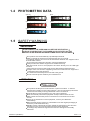
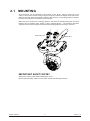
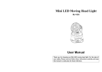
Version 1.0
WWW.YAGANG.COM
USER MANUAL
MX-COLOR
LED110
PART 1 PRODUCT (GENERAL)..............................................................1
1.1--PRODUCT INTRODUCTION....................................................................................... 2
1.2--PRODUCT FEATURES...............................................................................................2
1.3--TECHNICAL SPECIFICATIONS...................................................................................3
1.4--PHOTOMETRIC DATA................................................................................................4
1.5--SAFETY WARNING....................................................................................................4
PART 2 INSTALLATION.........................................................................5
2.1--MOUNTING................................................................................................................6
2.2-- SETTING UP (STAND ALONE)....................................................................................7
2.3--SETTING UP (MASTER/SLAVE)..................................................................................7
2.4--SETTING UP (DMX512 CONTROLLER).......................................................................8
PART 3 DISPLAY PANEL OPERATION................................................... 9
3.1--BASIC......................................................................................................................10
3.2--MENU......................................................................................................................11
3.3--SETTING DMX512 ADDRESS...................................................................................12
3.4--RUN MODE.............................................................................................................12
3.5--EDIT PROGRAM......................................................................................................13
3.6--SPECIAL OPTIONS..................................................................................................14
PART 4 OPERATION WITH DMX512.....................................................15
4.1--BASIC ADDRESSING...............................................................................................16
4.2--CHANNEL ASSIGNMENT..........................................................................................16
4.3--FUNCTION EXPLANATION.......................................................................................18
Par t
1.1
1.2
1.3
1.4
1.5
PRODUCT INTRODUCTION
PRODUCT FEATURES
TECHNICAL SPECIFICATIONS
PHOTOMETRIC DATA
SAFETY WARNING
PRODUCT (GENERAL)
1
1
1.1
PRODUCT INTRODUCTION
This product is designed for indoor use only. Suitable applications include wash or effect
lighting for architectural, stage or nightclub applications. Direct input of DMX512 signal
allows the fixtures to be controlled from any DMX512 controller. The fixture is fully
programmable with one custom program available and is supplied with two automatic
programs and two music-active programs (all accessible from DMX512 controller). This
product can be operated as a single unit or with multiple units for large applications.
1.2
PRODUCT FEATURES
RGB Dimmer 0-100%
Strobe
Automatic programs
Music-active programs
Custom program (programmable)
Auto-color sequence (variable speed)
LCD display
Fan speed control
DirectDMX512 input
No
2
ITEM
1
Arm
2
Head
3
Base
4
Power selector switch
5
DMX OUT
6
DMX IN
7
Power switch
8
Mic
9
LCD display
1
10
Enter
11
Down
12
Up
13
Mode
14
Power connector
3
8
7
9
4
5
POWER
MIC
110V~230V
6
POWER IN PUT
DMX OUT
MODE
UP
DOWN
ENTER
DMX IN
14
PRODUCT (GENERAL)
2
13
12
11
10
2006.11.15
1.3
TECHNICAL SPECIFICATIONS
Voltage
Rated Power
LED/Unit
Output/LED
100~120V...50/60Hz
220~240V...50/60Hz50W
50W
18pcs (6 X RED / 6 X GREEN / 6 X BLUE)
1W
LED Beam Angle 15 (30 Optional)
Cooling
Dimensions
Weight
Forced air convection
356 x 300 x 356mm
8.9Kg
13
5
13
250
5
15
115
359
300
149.25
54 0
90
102
43.78
94.25
278.5
PRODUCT (GENERAL)
3
2006.11.15
PHOTOMETRIC DATA
WHITE
1600
430
180
95
90 LUX
15
3
2
1
0
1
2
3
2
4
6
8
10 Diameter(m)
RED
1500
370
170
93
2
4
6
8
515
130
62
31
2
4
6
8
80 LUX
10 Diameter(m)
GREEN
645
170
72
50
40 LUX
15
3
2
1
0
1
2
3
3
2
1
0
1
2
3
15
RGB 100%
2
4
6
8
600
150
70
34
2
4
6
8
10 Diameter(m)
3
2
1
0
1
2
3
25 LUX
15
1.4
10 Diameter(m)
BLUE
1.5
30 LUX
15
3
2
1
0
1
2
3
10 Diameter(m)
SAFETY WARNING
IMPORTANT
ALWAYS READ THE USER MANUAL BEFORE OPERATION.
PLEASE CONFIRM THAT THE POWER SUPPLY STATED ON THE
PRODUCT IS THE SAME AS THE MAINS POWER SUPPLY IN YOUR AREA.
This product must be installed by a qualified professional.
Always operate the equipment as described in the user manual.
A minimum distance of 0.5m must be maintained between the equipment and
combustible surface.
The product must always be placed in a well ventilated area.
Always make sure that the equipment is installed securely.
DO NOT stand close to the equipment and stare directly into the LED light
source.
Always disconnect the power supply before attempting and maintenance.
Always make sure that the supporting structure is solid and can support the
combined weight of the products.
The earth wire must always be connected to the ground.
Do not touch the power cables if your hands are wet.
ATTENTION
This product left the place of manufacture in perfect condition. In order to
maintain this condition and for safe operation, the user must always follow the
instructions and safety warnings described in this user manual.
Avoid shaking or strong impacts to any part of the equipment.
Make sure that al parts of the equipment are kept clean and free of dust.
Always make sure that the power connections are connected correct and
secure.
If there is any malfunction of the equipment, contact your distributor
immediately.
When transferring the product, it is advisable to use the original packaging in
which the product left the factory.
Shields, lenses or ultraviolet screens shall be changed if they have become
damaged to such an extent that their effectiveness is impaired.
The lamp (LED) shall be changed if it has become damaged or thermally
deformed.
PRODUCT (GENERAL)
4
2006.11.15
Par t
2.1
2.2
2.3
2.4
MOUNTING
SETTING UP (STAND ALONE)
SETTING UP (MASTER/SLAVE)
SETTING UP (DMX512 CONTROLLER)
INSTALLATION
5
2
2.1
MOUNTING
The LED fixture can be operated in any position at any angle. When mounted on a flat
surface, the surface must be strong enough to support 10 times the weight of the fixture and
stable so that the will be no damage caused to the fixture or surrounding people or objects
because of movements of the fixture on the surface.
When the unit is mounted in a hanging position, the fixture is attached using the mounting
brackets and a standard truss clamp or other clamping device. The mounting brackets
supplied are mounted using quick-release locks allowing simple mounting or removal.
Quick-release lock
Safety cable
IMPORTANT SAFETY NOTE!!
Always use a safety cable when installing this unit!!
Be sure that the safety cable is connected to a solid load-bearing structure.
INSTALLATION
6
2006.11.15
2.2
SETTING UP (STAND ALONE)
The LED fixture can be used as a stand alone unit. The stand alone functions AUTO 1,
AUTO 2, SOUND 1, SOUND 2, CUSTOM 1 can be activated without the need to connect to
any controller or connecting to any other equipment.
Simply, access the <RUN> menu from the DISPLAY and select the target program to
activate.
2.3
SETTING UP (MASTER/SLAVE)
When units are connected in series using DMX512 signal cable connect the units as shown
in the diagram below
Connect the (male) 3 pin connector side of the DMX cable to the output (female) 3 pin
connector of the first (MASTER) fixture.
Connect the end of the cable coming from the MASTER fixture which will have a (female) 3
pin connector to the input connector of the next fixture consisting of a (male) 3 pin
connector.
Then proceed to connect from the output as stated above to the input of the following fixture
and so on.
Set the first unit in the series to one of the STAND ALONE modes as described in section
2.2
All other units in the series should be set to <SLAVE> from the <RUN> menu.
MASTER
INSTALLATION
7
SLAVE
SLAVE
2006.11.15
2.4
SETTING UP (DMX512 CONTROLLER)
When units are connected in series to a DMX512 controller and other DMX512 equipment,
connect the equipment as shown in the diagram below.
Connect the (male) 3 pin connector side of the DMX cable to the output (female) 3 pin
connector of the controller.
Connect the end of the cable coming from the controller which will have a (female) 3 pin
connector to the input connector of the next fixture consisting of a (male) 3 pin connector.
Then proceed to connect from the output as stated above to the input of the following fixture
and so on.
DMX512
CONTROLLER
INSTALLATION
8
2006.11.15
Par t
3.1
3.2
3.3
3.4
3.5
3.6
3
BASIC
MENU
SETTING DMX512 ADDRESS
RUN MODE
EDIT PROGRAM
SPECIAL OPTIONS
DISPLAY PANEL OPERATION
9
3.1
BASIC
The LED fixture is mounted with a LCD display and 4 control buttons.
MODE
UP
DOWN
ENTER
Scroll through the main menu or exit from the current sub-menu
Scroll 'UP' through the menu list or increase the value of the current function
Scroll 'DOWN' through the menu list or decrease the value of the current function
Enter the currently selected menu or confirm the current function value
DISPLAY PANEL OPERATION
10
2006.11.15
3.2
MENU
Welcome
Run
Auto 1
Auto 2
Sound 1
Sound 2
Custom
DMX
Slave
Edit Prg
Edit Program
Step 0
100
Pan
0
2 55
Titl
0
2 55
Red
0
Green 0
Blue
Option
Address 1
DISPLAY PANEL OPERATION
255
255
0
255
Strobe 0
255
Time
0
8
Fade
0
8
Reset Custom
Confirm Reset
Fan Speed
Low
High
Invert Pan
ON/OFF
Invert Tilt
Reset
Load Default
ON/OFF
499
11
2006.11.15
3.3
SETTING DMX512 ADDRESS
Welcome
Address 1
Address
Enter the Address
3.4
499
mode to set the DMX address
RUN MODE
Welcome
Run
Auto 1
Auto 2
Sound 1
Sound 2
Custom
DMX
Slave
Run
Enter the Run menu in order to select the operation mode of the fixture
For stand alone operation, select from the modes AUTO 1 , AUTO 2 ,
SOUND 1 , SOUND 2 & CUSTOM
For control with a DMX512 controller select DMX
To set a unit as a slave select Slave
DISPLAY PANEL OPERATION
12
2006.11.15
3.5
EDIT PROGRAM
Welcome
Edit Prg
Edit Program
Step 0
100
Pan
0
2 55
Titl
0
2 55
Red
0
Green 0
Blue
Reset Custom
Step
Select from 100 steps to create or edit
Steps that are not required should have the Time
255
255
0
255
Strobe 0
255
Time
0
8
Fade
0
8
Confirm Reset
set as 0
Pan
Set the PAN position of the LED fixture (0-255)
Tilt
Set the TILT position of the LED fixture (0-255)
Red , Green & Blue
Combine RED, GREEN & BLUE to create an infinite range of colors (0-255)
Strobe
Select the strobe speed from 0-24Hz
Time
Set the Time for the current step (0-8)
The unit of Time is 1 seconds
Fade
Set the [Fade] time of the current step (0-8)
The unit of [Fade time is 1 second
Reset Custom
Enter Reset Custom
DISPLAY PANEL OPERATION
in order to reset all settings in the CUSTOM mode
13
2006.11.15
3.6
SETTING DMX512 ADDRESS
Welcome
Option
Fan Speed
Low
High
Invert Pan
ON/OFF
Invert Tilt
Reset
Load Default
ON/OFF
Fan Speed
Set the Fan Speed as high or low
Note that when the fan speed is set to low that any overheating by the
unit will automatically change the fan speed to high
Invert Pan
Select On] in order to invert the PAN values
Invert Tilt
Select On in order to invert the TILT values
Reset
Select Reset
to reset the fixture
Load Default
Select Load Default to reset all settings in the fixture
(does not include CUSTOM mode)
DISPLAY PANEL OPERATION
14
2006.11.15
Par t
4.1
4.2
4.3
4
BASIC ADDRESSING
CHANNEL ASSIGNMENT
FUNCTION EXPLANATION
OPERATION WITH DMX512
15
4.1
BASIC ADDRESSING
It connect all of the units in series using standard DMX512 signal cable
It set the DMX512 address in the 'Address' menu
It is possible to have the same DMX address or independent addresses for each fixture.
4.2
CHANNEL ASSIGNMENT
CHANNEL
FUNCTION
1
PAN
2
TILT
3
PAN/TILT SPEED
4
RED
5
GREEN
6
BLUE / AUTO-MACRO SPEED
7
RGB MACRO, AUTO-MACRO & WHITE
8
DIMMER
9
STROBE
10
CONTROL MODE
CH1
%
Function
CH2
%
Function
CH3
%
Function
255
100
540
255
100
270
255
100
FAST
0
0.0
0
0.0
0
0.0
SLOW
CH4
%
Function
CH5
%
Function
CH6
%
Function
255
100
RED
255
100
GREEN
255
100
BLUE FAST
0
0.0
OFF
0
0.0
OFF
0
0.0
OFF
OPERATION WITH DMX512
16
SLOW
2006.11.15
%
CH7
Function
251
255
98.5
100
WHITE
241
250
94.5
98
AUTO-MACRO
216
240
84.5
94
RED UP/GREEN DOWN /BLUE 100%
186
215
73
84
RED 100%/GREEN UP/BLUE UP
156
185
61
72.5
RED 100%/GREEN 0%/BLUE DOWN
126
155
49.5
60.5
RED DOWN/GREEN 0%/BLUE 100%
96
125
37.5
49
RED 0%/GREEN DOWN/BLUE 100%
66
95
26
37
RED 0%/GREEN 100%/BLUE UP
36
65
14
25.5
RED DOWN / GREEN 100%/BLUE 0%
6
35
2.5
13.5
RED 100% / GREEN UP / BLUE 0%
0
5
2
NO FUNCTION
0
CH9
%
Function
255
100
24Hz
0
0.0
OPERATION WITH DMX512
%
CH10
216
255
84.5
176
215
69
136
175
96
135
56
CH8
%
Function
255
100
MAXIMUM
INTENSITY
0
0.0
MINIMUM
INTENSITY
Function
255
CUSTOM (AFTER 3 SECONDS)
84
SOUND 2 (AFTER 3 SECONDS)
53.5
68.5
SOUND 1 (AFTER 3 SECONDS)
37.5
53
AUTO 2 (AFTER 3 SECONDS)
95
22
37
AUTO 1 (AFTER 3 SECONDS)
46
55
18 2
1.5
RESET (AFTER 3 SECONDS)
0
45
0
17.5
NORMAL OPERATION
NO FUNCTION
17
2006.11.15
4.3
FUNCTION EXPLANATION
PAN
CH1 adjusts the PAN from 0 to 540
TILT
CH2 adjusts the TILT from 0 to 540
PAN/TILT SPEED
CH3 adjusts the speed of the PAN and TILT faders
RED, GREEN & BLUE
CH4, CH5 & CH6 control the intensity of each of the RED, GREEN & BLUE LEDs.
When the slider is at the highest position (255) the intensity of the color is the
maximum
CH4, CH5 & CH6 can be combined together to create over 16 million colors.
COLOR MACRO & WHITE
The COLOR MACRO allows the user to select from a linear range of colors
The range from 241-250 is an AUTO-MACRO.
When the AUTO-MACRO is selected, CH6 controls the speed of the AUTO-MACRO.
When the slider is at the top of the slider the color is WHITE
DIMMER
CH8 is an overall DIMMER for the currently selected / created color
STROBE
CH9 is the strobe channel and controls the speed of the strobe.
The strobe is with an adjustable speed with a maximum of 24Hz
CONTROL MODE
CH10 allows the user to access the internal programs in the fixture
CH10 also allows the unit to perform a reset.
Note that all functions from CH10 require a 3 second delay before activation.
OPERATION WITH DMX512
18
2006.11.15