1
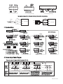
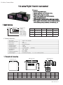
CA Series Counter Meter
CA series Digital Counter user manual
Features:
1. Dual line 6 digit LED displayˈ
display
2. Optional dimensionġ48×48,
dimension 48×48, 48x96, 72×72ˈ
72×72
3. Single counting, single relay outputˈ
output
4. Manual reset, automatic reset, key lock function
functionē
power fail memory function
functionˈ
5. Settable counting coefficient, NPN or PNP input selectableˈ
selectable
6. Widely applied to the industries relevant to timber machining,
food machinery, packing machinery, steel machining, etc.
1. Model Indication
CA
0
0: Design code
6: 6 digit
B: One alarm
R: Relay output
4:48W×48H(mm)
7:72W×72H(mm)
8:96W×48H(mm)
CA series counter
Dimension(mm)
Model
Digit
Alarm Output
Power supply
CA4-RB60
48W×48H×102L
6
One relay alarm
220VAC
CA7-RB60
72W×72H×100L
6
One relay alarm
110/220VAC
CA8-RB60
96W×48H×100L
6
One relay alarm
110/220VAC
2. Technical Parameter
Power Supply
Total Power Consumption
Relay Capacity
Output Power
Insulation Resistance
Insulation Strength
Counting Input Speed
Counting Range
Delay Time
Coefficient Setting Range
220VAC±10% 50H/60Hz
≤4W
250VAC/3A
DC18V±5V(≤25mA)
≥20MΩ
1.5KV/1M
(selectable)
≤1/30/300/1000Hz
0.01̚999999
0.01̚600.00s
0.01̚9999.99
External Reset Frequency
External Signal
2ǃ10ǃ100ǃ500Hz (selectable)
3. Dimension & Connection
Mounting size
Side face size
Front face size
A
G+0.5
-0
C
E
D
H
J +0.5
-0
B
K
F
Model
A
B
C
D
E
F
G
H(Min)
J
K(Min)
4:(48×48)
7:(72×72)
8:(48×96)
48
72
96
48
72
48
108
109
109
6
9.5
9
102
99.5
100
45
67
44.5
45.5
67.5
90
25
25
25
45.5
67.5
45
25
25
25
Remark
Unit: (mm) Tolerance ±0.5%(special annotation not be included)
KKCA101-A/2-1
110VAC 50Hz
CA4 Connecting Drawing
CA7 Connecting Drawing
CA8 Connecting Drawing
Note: Please subject to the connection drawing on the counter if any changes.
POWER
Bulge
proximity
sensor
Wheel M
POWER
18VDC
Wheel
OUT
0
GND
OUT
Rotary
CPIN CA Counter
Encoder
GND
GND
18VDC
CPIN CA Counter
GND
4. Operation Menu
Press SET key ≥3S
Measuring Status
Press
Parameter
setting status
key
Press & key
to change the
preset value
NPN / PNP Selection
NPN / PNP
input selection
Input speed
rate selection
Press SET key
Press SET key
Output
delay time(S)
Press SET key
Press SET key
Measuring Status
a. Please set the right PIN on the PCB board
inside the couter after selecting NPN or
PNP in the menu˄The
menu The default is NPN˅
NPN
S1
NPN PNP
Reset signal
frequency
selection
Decimal point
selection
Press SET key
S1
NPN PNP
b. Key lock selection(
)
= Level 0: No lock function
= Level 1: To lock RST key
= Level 2: To lock Ƹ key
= Level 3: To lock ƸRST key
Press SET key
Coefficient
setting
Power fail
memory
selection
Press SET key
Output mode
selection
Press SET key
Passwork
lock
Press SET key
Press SET key
5. Counter Output Mode Diagram
There are 4 types of output modes for option
option,, N, F, R, C.
N
Reset
Rese
F
Reset
Rese
C
R
Reset
Rese
Reset
Rese
999999
Outpu
Output
mode
mod
setting
settin
Counting SET
Counting SET
Display 0
Display 0
Output
Output
Actio
Action
after
Output and the counting valu
value
Counting will remain till reset signal.
up
Counting value goes on, output
willl remain till reset signal.
wil
Counting SET
Display 0
Output
When counting value reaches
setting value, the display value
and output will remain till the
setting delay time, then reset to
next counting automatically.
Counting SET
Display 0
Output
The coun
unter will rese
reset thee counting
value when it reaches the settin
setting
value,
val
e, but the ou
output
put will remain
till the setting delay time.
KKCA101-A/2-2