1
xT Nova NanoLab
User’s Manual
4022 262 52351/02
01/07/2007
Copyright © 2007
FEI Company
All rights reserved
Trademark Acknowledgments
FrameMaker™ is a trademark of Adobe Systems Incorporated.
Microsoft® is a registered trademark of Microsoft Corporation.
Windows2000™ and WindowsXP™ are trademarks of Microsoft Corporation.
Production Acknowledgments
This manual was produced using FrameMaker™ document publishing software
Technical Author
Mike Hayles
Martin Dufek
Contents
List of Figures
List of Tables
PREFACE
About this Manual . . . . . . . . . . . . . . . . . . . . . . . . . . . . . . . . . . . . . . . . . . . . . 1-i
How to Use this Manual . . . . . . . . . . . . . . . . . . . . . . . . . . . . . . . . . . . . . . . . 1-ii
Conventions for Controls . . . . . . . . . . . . . . . . . . . . . . . . . . . . . . . . . . . . . 1-ii
Finding What You Need . . . . . . . . . . . . . . . . . . . . . . . . . . . . . . . . . . . . . . . 1-ii
Chapter 1
SAFETY & HANDLING
Site Requirements . . . . . . . . . . . . . . . . . . . . . . . . . . . . . . . . . . . . . . . . . . . . .1-1
Electron Column Precautions . . . . . . . . . . . . . . . . . . . . . . . . . . . . . . . . . . . .1-1
Trained Service Personnel . . . . . . . . . . . . . . . . . . . . . . . . . . . . . . . . . . . . . . .1-2
User Maintenance . . . . . . . . . . . . . . . . . . . . . . . . . . . . . . . . . . . . . . . . . . . . .1-2
Terms and Symbols . . . . . . . . . . . . . . . . . . . . . . . . . . . . . . . . . . . . . . . . . . . .1-3
Symbols and messages. . . . . . . . . . . . . . . . . . . . . . . . . . . . . . . . . . . . . . . 1-3
Voltages . . . . . . . . . . . . . . . . . . . . . . . . . . . . . . . . . . . . . . . . . . . . . . . . . . . . .1-4
Interlocks . . . . . . . . . . . . . . . . . . . . . . . . . . . . . . . . . . . . . . . . . . . . . . . . . 1-4
Line Voltage . . . . . . . . . . . . . . . . . . . . . . . . . . . . . . . . . . . . . . . . . . . . . . . 1-4
Cords/Cables . . . . . . . . . . . . . . . . . . . . . . . . . . . . . . . . . . . . . . . . . . . . . . 1-4
Ground (Earth) . . . . . . . . . . . . . . . . . . . . . . . . . . . . . . . . . . . . . . . . . . . . . 1-5
Cover/Panels . . . . . . . . . . . . . . . . . . . . . . . . . . . . . . . . . . . . . . . . . . . . . . 1-5
Fuses. . . . . . . . . . . . . . . . . . . . . . . . . . . . . . . . . . . . . . . . . . . . . . . . . . . . . 1-6
Emergency Button . . . . . . . . . . . . . . . . . . . . . . . . . . . . . . . . . . . . . . . . . . . . .1-6
Emergency Off (EMO) Switches . . . . . . . . . . . . . . . . . . . . . . . . . . . . . . . 1-6
Chemicals . . . . . . . . . . . . . . . . . . . . . . . . . . . . . . . . . . . . . . . . . . . . . . . . . . . .1-7
Solvents . . . . . . . . . . . . . . . . . . . . . . . . . . . . . . . . . . . . . . . . . . . . . . . . . . 1-7
Nitrogen . . . . . . . . . . . . . . . . . . . . . . . . . . . . . . . . . . . . . . . . . . . . . . . . . . 1-7
Liquid Nitrogen . . . . . . . . . . . . . . . . . . . . . . . . . . . . . . . . . . . . . . . . . . . . 1-7
Miscellaneous Precautions . . . . . . . . . . . . . . . . . . . . . . . . . . . . . . . . . . . . . . .1-8
Electric Fans. . . . . . . . . . . . . . . . . . . . . . . . . . . . . . . . . . . . . . . . . . . . . . . 1-8
Pump Exhaust . . . . . . . . . . . . . . . . . . . . . . . . . . . . . . . . . . . . . . . . . . . . . 1-8
Corrosion . . . . . . . . . . . . . . . . . . . . . . . . . . . . . . . . . . . . . . . . . . . . . . . . . 1-8
Chapter 2
SYSTEM OVERVIEW
FIB/SEM Capabilities . . . . . . . . . . . . . . . . . . . . . . . . . . . . . . . . . . . . . . . . . .2-3
Control of the Beams . . . . . . . . . . . . . . . . . . . . . . . . . . . . . . . . . . . . . . . . 2-3
X-Ray Analysis Capability . . . . . . . . . . . . . . . . . . . . . . . . . . . . . . . . . . . 2-4
User Interface. . . . . . . . . . . . . . . . . . . . . . . . . . . . . . . . . . . . . . . . . . . . . . 2-4
Computerized Stage . . . . . . . . . . . . . . . . . . . . . . . . . . . . . . . . . . . . . . . . . 2-4
Optical Camera . . . . . . . . . . . . . . . . . . . . . . . . . . . . . . . . . . . . . . . . . . . . 2-4
4022 262 52351/02
Supervisor and User Log-on. . . . . . . . . . . . . . . . . . . . . . . . . . . . . . . . . . . 2-4
NanoLab Options . . . . . . . . . . . . . . . . . . . . . . . . . . . . . . . . . . . . . . . . . . . . . 2-5
Chapter 3
SYSTEM OPERATION
Nova NanoLab . . . . . . . . . . . . . . . . . . . . . . . . . . . . . . . . . . . . . . . . . . . . . . . 3-1
Overview. . . . . . . . . . . . . . . . . . . . . . . . . . . . . . . . . . . . . . . . . . . . . . . . . . 3-1
System Status . . . . . . . . . . . . . . . . . . . . . . . . . . . . . . . . . . . . . . . . . . . . . . . . 3-2
Vacuum Status . . . . . . . . . . . . . . . . . . . . . . . . . . . . . . . . . . . . . . . . . . . . . 3-2
Log-On / Log-Off . . . . . . . . . . . . . . . . . . . . . . . . . . . . . . . . . . . . . . . . . . . . . 3-3
Supervisor and User Log-On/Log-Off . . . . . . . . . . . . . . . . . . . . . . . . . . . 3-3
Launch UI Level . . . . . . . . . . . . . . . . . . . . . . . . . . . . . . . . . . . . . . . . . . . . 3-4
Leaving the System Overnight . . . . . . . . . . . . . . . . . . . . . . . . . . . . . . . . . . . 3-5
Overnight and weekends. . . . . . . . . . . . . . . . . . . . . . . . . . . . . . . . . . . . . . 3-5
Returning to operation . . . . . . . . . . . . . . . . . . . . . . . . . . . . . . . . . . . . . . . . . 3-6
Operation . . . . . . . . . . . . . . . . . . . . . . . . . . . . . . . . . . . . . . . . . . . . . . . . . 3-6
Standby Mode . . . . . . . . . . . . . . . . . . . . . . . . . . . . . . . . . . . . . . . . . . . . . . . . 3-7
Going into Standby Mode. . . . . . . . . . . . . . . . . . . . . . . . . . . . . . . . . . . . . 3-7
Startup After Standby . . . . . . . . . . . . . . . . . . . . . . . . . . . . . . . . . . . . . . . . . . 3-8
Startup. . . . . . . . . . . . . . . . . . . . . . . . . . . . . . . . . . . . . . . . . . . . . . . . . . . . 3-8
Complete System Shutdown . . . . . . . . . . . . . . . . . . . . . . . . . . . . . . . . . . . . 3-10
Shutdown . . . . . . . . . . . . . . . . . . . . . . . . . . . . . . . . . . . . . . . . . . . . . . . . 3-10
Startup from complete System Shutdown . . . . . . . . . . . . . . . . . . . . . . . . . 3-11
Startup. . . . . . . . . . . . . . . . . . . . . . . . . . . . . . . . . . . . . . . . . . . . . . . . . . . 3-11
Emergency Power Off (EMO) . . . . . . . . . . . . . . . . . . . . . . . . . . . . . . . . . . 3-13
What Happens during Power Failures . . . . . . . . . . . . . . . . . . . . . . . . . . . . 3-14
Chapter 4
USER INTERFACE
Other Software and Hardware . . . . . . . . . . . . . . . . . . . . . . . . . . . . . . . . .
User Access Privileges . . . . . . . . . . . . . . . . . . . . . . . . . . . . . . . . . . . . . . .
Software Interface Elements . . . . . . . . . . . . . . . . . . . . . . . . . . . . . . . . . . . . .
Icon . . . . . . . . . . . . . . . . . . . . . . . . . . . . . . . . . . . . . . . . . . . . . . . . . . . . . .
Pulldown Menus . . . . . . . . . . . . . . . . . . . . . . . . . . . . . . . . . . . . . . . . . . . .
Dialog Boxes . . . . . . . . . . . . . . . . . . . . . . . . . . . . . . . . . . . . . . . . . . . . . .
Radio Buttons . . . . . . . . . . . . . . . . . . . . . . . . . . . . . . . . . . . . . . . . . . . . . .
Check Boxes . . . . . . . . . . . . . . . . . . . . . . . . . . . . . . . . . . . . . . . . . . . . . . .
Command Buttons . . . . . . . . . . . . . . . . . . . . . . . . . . . . . . . . . . . . . . . . . .
List Boxes . . . . . . . . . . . . . . . . . . . . . . . . . . . . . . . . . . . . . . . . . . . . . . . . .
Property Editors . . . . . . . . . . . . . . . . . . . . . . . . . . . . . . . . . . . . . . . . . . . .
Continuous Control Adjusters . . . . . . . . . . . . . . . . . . . . . . . . . . . . . . . . .
Preset/Continuous Control Adjusters . . . . . . . . . . . . . . . . . . . . . . . . . . . .
Two-Dimensional X-Y Controls. . . . . . . . . . . . . . . . . . . . . . . . . . . . . . . .
4-1
4-1
4-2
4-2
4-2
4-2
4-3
4-3
4-3
4-3
4-3
4-4
4-4
4-4
4022 262 52351/02
Text Boxes . . . . . . . . . . . . . . . . . . . . . . . . . . . . . . . . . . . . . . . . . . . . . . . . 4-5
Progress dialogs . . . . . . . . . . . . . . . . . . . . . . . . . . . . . . . . . . . . . . . . . . . . 4-5
Tabbed Dialogs. . . . . . . . . . . . . . . . . . . . . . . . . . . . . . . . . . . . . . . . . . . . . 4-5
Help Functions . . . . . . . . . . . . . . . . . . . . . . . . . . . . . . . . . . . . . . . . . . . . . . . .4-6
Tool-Tips . . . . . . . . . . . . . . . . . . . . . . . . . . . . . . . . . . . . . . . . . . . . . . . . . 4-6
On-Line Documentation . . . . . . . . . . . . . . . . . . . . . . . . . . . . . . . . . . . . . 4-6
xT Control Interface Elements . . . . . . . . . . . . . . . . . . . . . . . . . . . . . . . . . . . .4-7
The Main Window . . . . . . . . . . . . . . . . . . . . . . . . . . . . . . . . . . . . . . . . . . . . .4-8
Interface Elements . . . . . . . . . . . . . . . . . . . . . . . . . . . . . . . . . . . . . . . . . . 4-9
The Title Bar . . . . . . . . . . . . . . . . . . . . . . . . . . . . . . . . . . . . . . . . . . . . . . . .4-10
The Menu Bar . . . . . . . . . . . . . . . . . . . . . . . . . . . . . . . . . . . . . . . . . . . . . . .4-10
File Menu . . . . . . . . . . . . . . . . . . . . . . . . . . . . . . . . . . . . . . . . . . . . . . . . . . .4-11
Edit Menu . . . . . . . . . . . . . . . . . . . . . . . . . . . . . . . . . . . . . . . . . . . . . . . . . .4-13
Detectors Menu . . . . . . . . . . . . . . . . . . . . . . . . . . . . . . . . . . . . . . . . . . . . . .4-14
Scan Menu . . . . . . . . . . . . . . . . . . . . . . . . . . . . . . . . . . . . . . . . . . . . . . . . . .4-15
Beam Menu . . . . . . . . . . . . . . . . . . . . . . . . . . . . . . . . . . . . . . . . . . . . . . . . .4-18
Patterning Menu . . . . . . . . . . . . . . . . . . . . . . . . . . . . . . . . . . . . . . . . . . . . .4-20
Stage Menu. . . . . . . . . . . . . . . . . . . . . . . . . . . . . . . . . . . . . . . . . . . . . . . . . .4-21
Tools Menu. . . . . . . . . . . . . . . . . . . . . . . . . . . . . . . . . . . . . . . . . . . . . . . . . .4-24
Window Menu . . . . . . . . . . . . . . . . . . . . . . . . . . . . . . . . . . . . . . . . . . . . . . .4-26
The Help Menu. . . . . . . . . . . . . . . . . . . . . . . . . . . . . . . . . . . . . . . . . . . . . . .4-28
Setting Preferences... . . . . . . . . . . . . . . . . . . . . . . . . . . . . . . . . . . . . . . . . . .4-29
The Preferences Dialogs . . . . . . . . . . . . . . . . . . . . . . . . . . . . . . . . . . . . 4-29
DataBar Tab . . . . . . . . . . . . . . . . . . . . . . . . . . . . . . . . . . . . . . . . . . . . . . 4-30
Units Tab . . . . . . . . . . . . . . . . . . . . . . . . . . . . . . . . . . . . . . . . . . . . . . . . 4-31
Presets Tab . . . . . . . . . . . . . . . . . . . . . . . . . . . . . . . . . . . . . . . . . . . . . . . 4-32
Scanning Tab . . . . . . . . . . . . . . . . . . . . . . . . . . . . . . . . . . . . . . . . . . . . . 4-33
The General Tab. . . . . . . . . . . . . . . . . . . . . . . . . . . . . . . . . . . . . . . . . . . 4-35
Movie Tab . . . . . . . . . . . . . . . . . . . . . . . . . . . . . . . . . . . . . . . . . . . . . . . 4-37
Sensitivity Tab . . . . . . . . . . . . . . . . . . . . . . . . . . . . . . . . . . . . . . . . . . . . 4-37
The Tool Bar . . . . . . . . . . . . . . . . . . . . . . . . . . . . . . . . . . . . . . . . . . . . . . . .4-38
The Data Bar . . . . . . . . . . . . . . . . . . . . . . . . . . . . . . . . . . . . . . . . . . . . . . . .4-42
Data Bar . . . . . . . . . . . . . . . . . . . . . . . . . . . . . . . . . . . . . . . . . . . . . . . . . 4-42
Pages and Modules . . . . . . . . . . . . . . . . . . . . . . . . . . . . . . . . . . . . . . . . . . . .4-43
Beam Control Page. . . . . . . . . . . . . . . . . . . . . . . . . . . . . . . . . . . . . . . . . . . .4-45
Vacuum. . . . . . . . . . . . . . . . . . . . . . . . . . . . . . . . . . . . . . . . . . . . . . . . . . 4-45
System . . . . . . . . . . . . . . . . . . . . . . . . . . . . . . . . . . . . . . . . . . . . . . . . . . 4-46
Column. . . . . . . . . . . . . . . . . . . . . . . . . . . . . . . . . . . . . . . . . . . . . . . . . . 4-46
Tuning . . . . . . . . . . . . . . . . . . . . . . . . . . . . . . . . . . . . . . . . . . . . . . . . . . 4-47
Magnification . . . . . . . . . . . . . . . . . . . . . . . . . . . . . . . . . . . . . . . . . . . . . 4-48
Beam . . . . . . . . . . . . . . . . . . . . . . . . . . . . . . . . . . . . . . . . . . . . . . . . . . . 4-48
4022 262 52351/02
Rotation . . . . . . . . . . . . . . . . . . . . . . . . . . . . . . . . . . . . . . . . . . . . . . . . .
Detectors . . . . . . . . . . . . . . . . . . . . . . . . . . . . . . . . . . . . . . . . . . . . . . . . .
Status. . . . . . . . . . . . . . . . . . . . . . . . . . . . . . . . . . . . . . . . . . . . . . . . . . . .
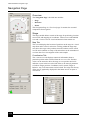
Navigation Page . . . . . . . . . . . . . . . . . . . . . . . . . . . . . . . . . . . . . . . . . . . . .
Overview. . . . . . . . . . . . . . . . . . . . . . . . . . . . . . . . . . . . . . . . . . . . . . . . .
Stage . . . . . . . . . . . . . . . . . . . . . . . . . . . . . . . . . . . . . . . . . . . . . . . . . . . .
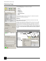
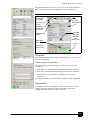
Patterning Page . . . . . . . . . . . . . . . . . . . . . . . . . . . . . . . . . . . . . . . . . . . . .
Pattern . . . . . . . . . . . . . . . . . . . . . . . . . . . . . . . . . . . . . . . . . . . . . . . . . . .
Progress. . . . . . . . . . . . . . . . . . . . . . . . . . . . . . . . . . . . . . . . . . . . . . . . . .
Omniprobe . . . . . . . . . . . . . . . . . . . . . . . . . . . . . . . . . . . . . . . . . . . . . . .
Gas Injection. . . . . . . . . . . . . . . . . . . . . . . . . . . . . . . . . . . . . . . . . . . . . .
End Point Monitor (EPM) . . . . . . . . . . . . . . . . . . . . . . . . . . . . . . . . . . .
Processing Page. . . . . . . . . . . . . . . . . . . . . . . . . . . . . . . . . . . . . . . . . . . . . .
Measurement / Annotation . . . . . . . . . . . . . . . . . . . . . . . . . . . . . . . . . . .
Digital zoom . . . . . . . . . . . . . . . . . . . . . . . . . . . . . . . . . . . . . . . . . . . . . .
Enhanced Image . . . . . . . . . . . . . . . . . . . . . . . . . . . . . . . . . . . . . . . . . . .
Detector Page . . . . . . . . . . . . . . . . . . . . . . . . . . . . . . . . . . . . . . . . . . . . . . .
Detector settings . . . . . . . . . . . . . . . . . . . . . . . . . . . . . . . . . . . . . . . . . . .
Charge Neutralizer (option) . . . . . . . . . . . . . . . . . . . . . . . . . . . . . . . . . .
Sample Preparation Page . . . . . . . . . . . . . . . . . . . . . . . . . . . . . . . . . . . . . .
Pattern . . . . . . . . . . . . . . . . . . . . . . . . . . . . . . . . . . . . . . . . . . . . . . . . . . .
Progress. . . . . . . . . . . . . . . . . . . . . . . . . . . . . . . . . . . . . . . . . . . . . . . . . .
Omniprobe . . . . . . . . . . . . . . . . . . . . . . . . . . . . . . . . . . . . . . . . . . . . . . .
Gas Injection. . . . . . . . . . . . . . . . . . . . . . . . . . . . . . . . . . . . . . . . . . . . . .
Alignments Page . . . . . . . . . . . . . . . . . . . . . . . . . . . . . . . . . . . . . . . . . . . .
Alignments . . . . . . . . . . . . . . . . . . . . . . . . . . . . . . . . . . . . . . . . . . . . . . .
Instructions . . . . . . . . . . . . . . . . . . . . . . . . . . . . . . . . . . . . . . . . . . . . . . .
No Step . . . . . . . . . . . . . . . . . . . . . . . . . . . . . . . . . . . . . . . . . . . . . . . . . .
Alignment allocation . . . . . . . . . . . . . . . . . . . . . . . . . . . . . . . . . . . . . . .
Status. . . . . . . . . . . . . . . . . . . . . . . . . . . . . . . . . . . . . . . . . . . . . . . . . . . . . .
Status Module . . . . . . . . . . . . . . . . . . . . . . . . . . . . . . . . . . . . . . . . . . . . .
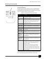
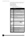
Entering Commands . . . . . . . . . . . . . . . . . . . . . . . . . . . . . . . . . . . . . . . . . .
Using the Mouse . . . . . . . . . . . . . . . . . . . . . . . . . . . . . . . . . . . . . . . . . . .
Using the Keyboard . . . . . . . . . . . . . . . . . . . . . . . . . . . . . . . . . . . . . . . .
Hardware Interface Elements . . . . . . . . . . . . . . . . . . . . . . . . . . . . . . . . . . .
LCD Monitors. . . . . . . . . . . . . . . . . . . . . . . . . . . . . . . . . . . . . . . . . . . . .
The System Computer . . . . . . . . . . . . . . . . . . . . . . . . . . . . . . . . . . . . . .
Stage Controls. . . . . . . . . . . . . . . . . . . . . . . . . . . . . . . . . . . . . . . . . . . . .
Manual User Interface . . . . . . . . . . . . . . . . . . . . . . . . . . . . . . . . . . . . . .
Chapter 5
4-49
4-49
4-49
4-50
4-50
4-50
4-52
4-52
4-53
4-53
4-54
4-54
4-56
4-56
4-57
4-58
4-60
4-60
4-60
4-61
4-61
4-62
4-62
4-62
4-64
4-64
4-64
4-64
4-64
4-65
4-65
4-67
4-67
4-68
4-73
4-73
4-73
4-73
4-73
WORKING WITH NOVA NANOLAB
4022 262 52351/02
Starting the xT-UI . . . . . . . . . . . . . . . . . . . . . . . . . . . . . . . . . . . . . . . . . . . . .5-2
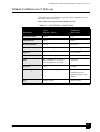
Default Conditions at xT Start-up . . . . . . . . . . . . . . . . . . . . . . . . . . . . . . . . .5-3
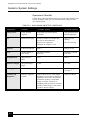
Guide to System Settings . . . . . . . . . . . . . . . . . . . . . . . . . . . . . . . . . . . . . . . .5-4
Operations Checklist . . . . . . . . . . . . . . . . . . . . . . . . . . . . . . . . . . . . . . . . 5-4
Beginning Your Session . . . . . . . . . . . . . . . . . . . . . . . . . . . . . . . . . . . . . . . . .5-5
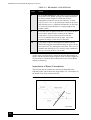
Importance of Beam Coincidence . . . . . . . . . . . . . . . . . . . . . . . . . . . . . . 5-6
Ending Your Session . . . . . . . . . . . . . . . . . . . . . . . . . . . . . . . . . . . . . . . . . . .5-7
Preparing the Sample . . . . . . . . . . . . . . . . . . . . . . . . . . . . . . . . . . . . . . . . . . .5-8
Needed Tools and Supplies . . . . . . . . . . . . . . . . . . . . . . . . . . . . . . . . . . . 5-8
Preparing the Sample . . . . . . . . . . . . . . . . . . . . . . . . . . . . . . . . . . . . . . . . 5-8
Mounting the Sample on the Holder . . . . . . . . . . . . . . . . . . . . . . . . . . . . 5-8
Maximum Sample Dimensions . . . . . . . . . . . . . . . . . . . . . . . . . . . . . . . . 5-8
Exchanging samples . . . . . . . . . . . . . . . . . . . . . . . . . . . . . . . . . . . . . . . . . . . .5-9
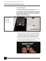
TEM Grid sample handling (option) . . . . . . . . . . . . . . . . . . . . . . . . . . . . . .5-10
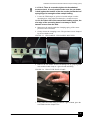
Loading TEM grids . . . . . . . . . . . . . . . . . . . . . . . . . . . . . . . . . . . . . . . . 5-10
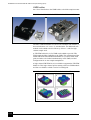
UMB holder . . . . . . . . . . . . . . . . . . . . . . . . . . . . . . . . . . . . . . . . . . . . . . 5-12
Obtaining an Image . . . . . . . . . . . . . . . . . . . . . . . . . . . . . . . . . . . . . . . . . . .5-13
How an Image is Produced . . . . . . . . . . . . . . . . . . . . . . . . . . . . . . . . . . 5-13
Relationship Sample to Image . . . . . . . . . . . . . . . . . . . . . . . . . . . . . . . . 5-13
Set up for Imaging . . . . . . . . . . . . . . . . . . . . . . . . . . . . . . . . . . . . . . . . . 5-14
Detectors for Nova NanoLab . . . . . . . . . . . . . . . . . . . . . . . . . . . . . . . . . . . .5-15
Imaging Detectors (general). . . . . . . . . . . . . . . . . . . . . . . . . . . . . . . . . . 5-15
Changing Detectors or Custom mode . . . . . . . . . . . . . . . . . . . . . . . . . . 5-16
Standard Imaging Detectors . . . . . . . . . . . . . . . . . . . . . . . . . . . . . . . . . . . . .5-17
ETD . . . . . . . . . . . . . . . . . . . . . . . . . . . . . . . . . . . . . . . . . . . . . . . . . . . . 5-17
TLD . . . . . . . . . . . . . . . . . . . . . . . . . . . . . . . . . . . . . . . . . . . . . . . . . . . . 5-18
Optional Imaging Detectors . . . . . . . . . . . . . . . . . . . . . . . . . . . . . . . . . . . . .5-19
CDEM (Option) . . . . . . . . . . . . . . . . . . . . . . . . . . . . . . . . . . . . . . . . . . . 5-19
Custom effect on Beam Shift . . . . . . . . . . . . . . . . . . . . . . . . . . . . . . . . . 5-19
STEM 1 (Option) . . . . . . . . . . . . . . . . . . . . . . . . . . . . . . . . . . . . . . . . . . 5-20
Retractable STEM 2 detector (Option) . . . . . . . . . . . . . . . . . . . . . . . . . 5-24
Optimizing the Image . . . . . . . . . . . . . . . . . . . . . . . . . . . . . . . . . . . . . . . . . .5-25
Changing Scan Speeds . . . . . . . . . . . . . . . . . . . . . . . . . . . . . . . . . . . . . . 5-25
Contrast and Brightness . . . . . . . . . . . . . . . . . . . . . . . . . . . . . . . . . . . . . 5-25
Correcting Contrast and Brightness . . . . . . . . . . . . . . . . . . . . . . . . . . . . 5-26
Auto Contrast and Brightness . . . . . . . . . . . . . . . . . . . . . . . . . . . . . . . . 5-26
Correcting Focus . . . . . . . . . . . . . . . . . . . . . . . . . . . . . . . . . . . . . . . . . . 5-27
Auto Focus . . . . . . . . . . . . . . . . . . . . . . . . . . . . . . . . . . . . . . . . . . . . . . . 5-28
Correcting Astigmatism . . . . . . . . . . . . . . . . . . . . . . . . . . . . . . . . . . . . . 5-29
Auto Lens \ Stigmator Alignment . . . . . . . . . . . . . . . . . . . . . . . . . . . . . 5-30
Selecting Beam Conditions . . . . . . . . . . . . . . . . . . . . . . . . . . . . . . . . . . . . .5-31
4022 262 52351/02
High Voltage and Beam Current. . . . . . . . . . . . . . . . . . . . . . . . . . . . . . .
E-Beam Aperture Strip . . . . . . . . . . . . . . . . . . . . . . . . . . . . . . . . . . . . . .
Aperture Loading Guidelines . . . . . . . . . . . . . . . . . . . . . . . . . . . . . . . . .
Selecting E-Beam Apertures. . . . . . . . . . . . . . . . . . . . . . . . . . . . . . . . . .
Strip Aperture Alignment Procedure . . . . . . . . . . . . . . . . . . . . . . . . . . .
I-Beam Apertures . . . . . . . . . . . . . . . . . . . . . . . . . . . . . . . . . . . . . . . . . .
Optimal I-Beam Currents . . . . . . . . . . . . . . . . . . . . . . . . . . . . . . . . . . . .
I-Beam Aperture Alignment . . . . . . . . . . . . . . . . . . . . . . . . . . . . . . . . . .
Working with magnification . . . . . . . . . . . . . . . . . . . . . . . . . . . . . . . . . . . .
Principle . . . . . . . . . . . . . . . . . . . . . . . . . . . . . . . . . . . . . . . . . . . . . . . . .
Magnification . . . . . . . . . . . . . . . . . . . . . . . . . . . . . . . . . . . . . . . . . . . . .
Choosing a Final Lens Mode . . . . . . . . . . . . . . . . . . . . . . . . . . . . . . . . . . .
Mode 1 . . . . . . . . . . . . . . . . . . . . . . . . . . . . . . . . . . . . . . . . . . . . . . . . . .
Mode 2 . . . . . . . . . . . . . . . . . . . . . . . . . . . . . . . . . . . . . . . . . . . . . . . . . .
Mode 3 . . . . . . . . . . . . . . . . . . . . . . . . . . . . . . . . . . . . . . . . . . . . . . . . . .
Taking a Snapshot. . . . . . . . . . . . . . . . . . . . . . . . . . . . . . . . . . . . . . . . . . . .
Snapshot Setup . . . . . . . . . . . . . . . . . . . . . . . . . . . . . . . . . . . . . . . . . . . .
How to Use Snapshot . . . . . . . . . . . . . . . . . . . . . . . . . . . . . . . . . . . . . . .
Taking a Photo . . . . . . . . . . . . . . . . . . . . . . . . . . . . . . . . . . . . . . . . . . . . . .
Photo Setup. . . . . . . . . . . . . . . . . . . . . . . . . . . . . . . . . . . . . . . . . . . . . . .
Single Images Saving / Opening. . . . . . . . . . . . . . . . . . . . . . . . . . . . . . . . .
Save. . . . . . . . . . . . . . . . . . . . . . . . . . . . . . . . . . . . . . . . . . . . . . . . . . . . .
Save As... . . . . . . . . . . . . . . . . . . . . . . . . . . . . . . . . . . . . . . . . . . . . . . . .
Open.... . . . . . . . . . . . . . . . . . . . . . . . . . . . . . . . . . . . . . . . . . . . . . . . . . .
Movie (multiple image capture) . . . . . . . . . . . . . . . . . . . . . . . . . . . . . . . . .
Image capture with Movie . . . . . . . . . . . . . . . . . . . . . . . . . . . . . . . . . . .
The Preferences Dialogue. . . . . . . . . . . . . . . . . . . . . . . . . . . . . . . . . . . .
Movie Procedure . . . . . . . . . . . . . . . . . . . . . . . . . . . . . . . . . . . . . . . . . . . . .
Start, Pause and Stop . . . . . . . . . . . . . . . . . . . . . . . . . . . . . . . . . . . . . . .
Recording a Movie . . . . . . . . . . . . . . . . . . . . . . . . . . . . . . . . . . . . . . . . .
FEI Movie Creator . . . . . . . . . . . . . . . . . . . . . . . . . . . . . . . . . . . . . . . . . . .
FEI Movie Creator . . . . . . . . . . . . . . . . . . . . . . . . . . . . . . . . . . . . . . . . .
Playing a Movie . . . . . . . . . . . . . . . . . . . . . . . . . . . . . . . . . . . . . . . . . . .
Image Printing. . . . . . . . . . . . . . . . . . . . . . . . . . . . . . . . . . . . . . . . . . . . . . .
Print... . . . . . . . . . . . . . . . . . . . . . . . . . . . . . . . . . . . . . . . . . . . . . . . . . . .
Import and Export . . . . . . . . . . . . . . . . . . . . . . . . . . . . . . . . . . . . . . . . . . . .
Import . . . . . . . . . . . . . . . . . . . . . . . . . . . . . . . . . . . . . . . . . . . . . . . . . . .
Export . . . . . . . . . . . . . . . . . . . . . . . . . . . . . . . . . . . . . . . . . . . . . . . . . . .
Patterning . . . . . . . . . . . . . . . . . . . . . . . . . . . . . . . . . . . . . . . . . . . . . . . . . .
Patterning Tools . . . . . . . . . . . . . . . . . . . . . . . . . . . . . . . . . . . . . . . . . . .
Magnification and Patterns . . . . . . . . . . . . . . . . . . . . . . . . . . . . . . . . . . .
5-31
5-32
5-32
5-33
5-33
5-34
5-34
5-35
5-36
5-36
5-36
5-38
5-38
5-38
5-38
5-39
5-39
5-40
5-41
5-41
5-42
5-42
5-42
5-43
5-44
5-44
5-44
5-47
5-47
5-47
5-49
5-49
5-52
5-53
5-53
5-54
5-54
5-54
5-55
5-56
5-58
4022 262 52351/02
Selecting a Pattern . . . . . . . . . . . . . . . . . . . . . . . . . . . . . . . . . . . . . . . . . 5-59
Editing Patterns . . . . . . . . . . . . . . . . . . . . . . . . . . . . . . . . . . . . . . . . . . . 5-59
Serial Patterning. . . . . . . . . . . . . . . . . . . . . . . . . . . . . . . . . . . . . . . . . . . 5-61
Parallel Patterning . . . . . . . . . . . . . . . . . . . . . . . . . . . . . . . . . . . . . . . . . 5-61
Patterning Progress . . . . . . . . . . . . . . . . . . . . . . . . . . . . . . . . . . . . . . . . 5-61
Milling Order of Patterns . . . . . . . . . . . . . . . . . . . . . . . . . . . . . . . . . . . . 5-62
Application Files . . . . . . . . . . . . . . . . . . . . . . . . . . . . . . . . . . . . . . . . . . . . .5-63
Choosing an Application File . . . . . . . . . . . . . . . . . . . . . . . . . . . . . . . . 5-63
The non-gas assisted application file . . . . . . . . . . . . . . . . . . . . . . . . . . . 5-63
The gas-assisted application file . . . . . . . . . . . . . . . . . . . . . . . . . . . . . . 5-64
Editing Application Files . . . . . . . . . . . . . . . . . . . . . . . . . . . . . . . . . . . . 5-65
Multi-pass. . . . . . . . . . . . . . . . . . . . . . . . . . . . . . . . . . . . . . . . . . . . . . . . 5-68
The Gas Injection System (GIS) . . . . . . . . . . . . . . . . . . . . . . . . . . . . . . . . .5-69
Gas Injection . . . . . . . . . . . . . . . . . . . . . . . . . . . . . . . . . . . . . . . . . . . . . 5-69
Gas Types . . . . . . . . . . . . . . . . . . . . . . . . . . . . . . . . . . . . . . . . . . . . . . . . 5-69
Setting up the GIS . . . . . . . . . . . . . . . . . . . . . . . . . . . . . . . . . . . . . . . . . 5-69
The End Point Monitor (EPM) . . . . . . . . . . . . . . . . . . . . . . . . . . . . . . . . . . .5-71
The EPM . . . . . . . . . . . . . . . . . . . . . . . . . . . . . . . . . . . . . . . . . . . . . . . . 5-71
Setting up the EPM for monitoring . . . . . . . . . . . . . . . . . . . . . . . . . . . . 5-72
Real Time Monitor (RTM). . . . . . . . . . . . . . . . . . . . . . . . . . . . . . . . . . . . . .5-73
Introduction . . . . . . . . . . . . . . . . . . . . . . . . . . . . . . . . . . . . . . . . . . . . . . 5-73
Beam Coincidence . . . . . . . . . . . . . . . . . . . . . . . . . . . . . . . . . . . . . . . . . . . .5-76
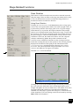
Beam Coincidence for the Electron and Ion Columns. . . . . . . . . . . . . . 5-76
Milling a Pattern . . . . . . . . . . . . . . . . . . . . . . . . . . . . . . . . . . . . . . . . . . . . . .5-77
Start a Milling Pattern . . . . . . . . . . . . . . . . . . . . . . . . . . . . . . . . . . . . . . 5-77
Stopping and Restarting . . . . . . . . . . . . . . . . . . . . . . . . . . . . . . . . . . . . . 5-78
Milling in Spot Mode. . . . . . . . . . . . . . . . . . . . . . . . . . . . . . . . . . . . . . . 5-79
Creating Cross Sections . . . . . . . . . . . . . . . . . . . . . . . . . . . . . . . . . . . . . . . .5-80
Making the Cross Section . . . . . . . . . . . . . . . . . . . . . . . . . . . . . . . . . . . 5-80
Viewing the Cross Section . . . . . . . . . . . . . . . . . . . . . . . . . . . . . . . . . . . . .5-83
Using the Measurement functions . . . . . . . . . . . . . . . . . . . . . . . . . . . . . . . .5-87
Using the Annotations functions . . . . . . . . . . . . . . . . . . . . . . . . . . . . . . . . .5-89
Use of Annotations. . . . . . . . . . . . . . . . . . . . . . . . . . . . . . . . . . . . . . . . . 5-90
Editing Measurements / Annotations. . . . . . . . . . . . . . . . . . . . . . . . . . . 5-91
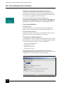
FEI User Management Software . . . . . . . . . . . . . . . . . . . . . . . . . . . . . . . . .5-92
Control possibilities . . . . . . . . . . . . . . . . . . . . . . . . . . . . . . . . . . . . . . . . 5-92
FEI Account Administrators . . . . . . . . . . . . . . . . . . . . . . . . . . . . . . . . . 5-92
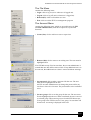
The File Menu . . . . . . . . . . . . . . . . . . . . . . . . . . . . . . . . . . . . . . . . . . . . 5-93
The Account Menu. . . . . . . . . . . . . . . . . . . . . . . . . . . . . . . . . . . . . . . . . 5-93
The Userdata menu . . . . . . . . . . . . . . . . . . . . . . . . . . . . . . . . . . . . . . . . 5-94
The Help Menu . . . . . . . . . . . . . . . . . . . . . . . . . . . . . . . . . . . . . . . . . . . 5-94
4022 262 52351/02
Account Logging . . . . . . . . . . . . . . . . . . . . . . . . . . . . . . . . . . . . . . . . . . 5-94
Chapter 6
STAGES
NanoLab 200 Stage. . . . . . . . . . . . . . . . . . . . . . . . . . . . . . . . . . . . . . . . . . . . 6-2
Standard Sample Holders . . . . . . . . . . . . . . . . . . . . . . . . . . . . . . . . . . . . . 6-5
NanoLab 600 Stage. . . . . . . . . . . . . . . . . . . . . . . . . . . . . . . . . . . . . . . . . . . . 6-6
Standard Sample Holders . . . . . . . . . . . . . . . . . . . . . . . . . . . . . . . . . . . . . 6-8
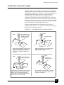
Finding the Eucentric Height . . . . . . . . . . . . . . . . . . . . . . . . . . . . . . . . . . . . 6-9
Finding Eucentric Height . . . . . . . . . . . . . . . . . . . . . . . . . . . . . . . . . . . . 6-10
Aligning Beams at the Eucentric Height . . . . . . . . . . . . . . . . . . . . . . . . 6-10
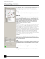
Software Stage Functions . . . . . . . . . . . . . . . . . . . . . . . . . . . . . . . . . . . . . . 6-12
Stage . . . . . . . . . . . . . . . . . . . . . . . . . . . . . . . . . . . . . . . . . . . . . . . . . . . . 6-12
Map tab . . . . . . . . . . . . . . . . . . . . . . . . . . . . . . . . . . . . . . . . . . . . . . . . . . 6-12
Map Elements . . . . . . . . . . . . . . . . . . . . . . . . . . . . . . . . . . . . . . . . . . . . . . . 6-14
Map Area . . . . . . . . . . . . . . . . . . . . . . . . . . . . . . . . . . . . . . . . . . . . . . . . 6-14
Map dialog . . . . . . . . . . . . . . . . . . . . . . . . . . . . . . . . . . . . . . . . . . . . . . . 6-15
Coordinates Tab . . . . . . . . . . . . . . . . . . . . . . . . . . . . . . . . . . . . . . . . . . . 6-16
Editing a coordinate . . . . . . . . . . . . . . . . . . . . . . . . . . . . . . . . . . . . . . . . 6-17
Tilt Correction Tab . . . . . . . . . . . . . . . . . . . . . . . . . . . . . . . . . . . . . . . . . 6-19
Tilt Angle . . . . . . . . . . . . . . . . . . . . . . . . . . . . . . . . . . . . . . . . . . . . . . . . 6-19
How to make Stage Movements . . . . . . . . . . . . . . . . . . . . . . . . . . . . . . . . . 6-20
Track . . . . . . . . . . . . . . . . . . . . . . . . . . . . . . . . . . . . . . . . . . . . . . . . . . . . 6-20
Get. . . . . . . . . . . . . . . . . . . . . . . . . . . . . . . . . . . . . . . . . . . . . . . . . . . . . . 6-21
Stage Frame Shift . . . . . . . . . . . . . . . . . . . . . . . . . . . . . . . . . . . . . . . . . . 6-21
xT Align Feature. . . . . . . . . . . . . . . . . . . . . . . . . . . . . . . . . . . . . . . . . . . 6-22
Compucentric Rotation. . . . . . . . . . . . . . . . . . . . . . . . . . . . . . . . . . . . . . 6-24
Define User Units . . . . . . . . . . . . . . . . . . . . . . . . . . . . . . . . . . . . . . . . . . 6-25
User Units . . . . . . . . . . . . . . . . . . . . . . . . . . . . . . . . . . . . . . . . . . . . . . . . 6-28
Stage Related Functions . . . . . . . . . . . . . . . . . . . . . . . . . . . . . . . . . . . . . . . 6-29
Scan Rotation . . . . . . . . . . . . . . . . . . . . . . . . . . . . . . . . . . . . . . . . . . . . . 6-29
Chapter 7
MAINTENANCE
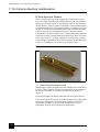
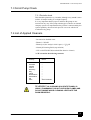
7.1 E-Column Aperture maintenance . . . . . . . . . . . . . . . . . . . . . . . . . . . . . .
E-Strip Aperture Module . . . . . . . . . . . . . . . . . . . . . . . . . . . . . . . . . . . . .
7.2 Stage maintenance. . . . . . . . . . . . . . . . . . . . . . . . . . . . . . . . . . . . . . . . . .
Specimen Holders. . . . . . . . . . . . . . . . . . . . . . . . . . . . . . . . . . . . . . . . . . .
Stage mechanics . . . . . . . . . . . . . . . . . . . . . . . . . . . . . . . . . . . . . . . . . . . .
7.3 Scroll Pump Check . . . . . . . . . . . . . . . . . . . . . . . . . . . . . . . . . . . . . . . . .
7.4 List of Applied Cleaners . . . . . . . . . . . . . . . . . . . . . . . . . . . . . . . . . . . .
7-2
7-2
7-4
7-4
7-4
7-5
7-5
4022 262 52351/02
Chapter 8
HARD & SOFTWARE OPTIONS
AutoFIB Software . . . . . . . . . . . . . . . . . . . . . . . . . . . . . . . . . . . . . . . . . . . . .8-2
Installing AutoFIB . . . . . . . . . . . . . . . . . . . . . . . . . . . . . . . . . . . . . . . . . . . . .8-3
AutoFIB Title Bar . . . . . . . . . . . . . . . . . . . . . . . . . . . . . . . . . . . . . . . . . . . . .8-3
AutoFIB Menus . . . . . . . . . . . . . . . . . . . . . . . . . . . . . . . . . . . . . . . . . . . . . . .8-4
File Menu . . . . . . . . . . . . . . . . . . . . . . . . . . . . . . . . . . . . . . . . . . . . . . . . 8-4
Play Menu . . . . . . . . . . . . . . . . . . . . . . . . . . . . . . . . . . . . . . . . . . . . . . . . 8-4
Logging Menu . . . . . . . . . . . . . . . . . . . . . . . . . . . . . . . . . . . . . . . . . . . . . 8-5
Options Menu. . . . . . . . . . . . . . . . . . . . . . . . . . . . . . . . . . . . . . . . . . . . . . 8-6
Set-Up Menu . . . . . . . . . . . . . . . . . . . . . . . . . . . . . . . . . . . . . . . . . . . . . . 8-7
Drift Control. . . . . . . . . . . . . . . . . . . . . . . . . . . . . . . . . . . . . . . . . . . . . . . 8-7
Default Information . . . . . . . . . . . . . . . . . . . . . . . . . . . . . . . . . . . . . . . . . 8-7
Dynamic Drift Control . . . . . . . . . . . . . . . . . . . . . . . . . . . . . . . . . . . . . . 8-10
Scripts . . . . . . . . . . . . . . . . . . . . . . . . . . . . . . . . . . . . . . . . . . . . . . . . . . . . . .8-11
Parameters . . . . . . . . . . . . . . . . . . . . . . . . . . . . . . . . . . . . . . . . . . . . . . . 8-11
Positions . . . . . . . . . . . . . . . . . . . . . . . . . . . . . . . . . . . . . . . . . . . . . . . . . 8-13
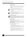
Creating and Running a Script . . . . . . . . . . . . . . . . . . . . . . . . . . . . . . . . . . .8-14
Creating a Script. . . . . . . . . . . . . . . . . . . . . . . . . . . . . . . . . . . . . . . . . . . 8-14
Previewing a Script . . . . . . . . . . . . . . . . . . . . . . . . . . . . . . . . . . . . . . . . 8-14
AutoRun Mode. . . . . . . . . . . . . . . . . . . . . . . . . . . . . . . . . . . . . . . . . . . . 8-14
Messages . . . . . . . . . . . . . . . . . . . . . . . . . . . . . . . . . . . . . . . . . . . . . . . . . . .8-16
Log Messages. . . . . . . . . . . . . . . . . . . . . . . . . . . . . . . . . . . . . . . . . . . . . 8-16
Error Messages. . . . . . . . . . . . . . . . . . . . . . . . . . . . . . . . . . . . . . . . . . . . 8-16
Additional Notes . . . . . . . . . . . . . . . . . . . . . . . . . . . . . . . . . . . . . . . . . . 8-17
Log File Examples . . . . . . . . . . . . . . . . . . . . . . . . . . . . . . . . . . . . . . . . . 8-17
Patterns in AutoFIB Script. . . . . . . . . . . . . . . . . . . . . . . . . . . . . . . . . . . 8-17
Using a Subscript . . . . . . . . . . . . . . . . . . . . . . . . . . . . . . . . . . . . . . . . . . 8-18
Auto Slice & View Software . . . . . . . . . . . . . . . . . . . . . . . . . . . . . . . . . . . .8-20
Contents of This Document . . . . . . . . . . . . . . . . . . . . . . . . . . . . . . . . . . 8-20
How Auto S&V Works . . . . . . . . . . . . . . . . . . . . . . . . . . . . . . . . . . . . . 8-20
Launching Auto S&V . . . . . . . . . . . . . . . . . . . . . . . . . . . . . . . . . . . . . . 8-22
User Interface . . . . . . . . . . . . . . . . . . . . . . . . . . . . . . . . . . . . . . . . . . . . . . . .8-23
Menu Commands . . . . . . . . . . . . . . . . . . . . . . . . . . . . . . . . . . . . . . . . . 8-23
Option Groups . . . . . . . . . . . . . . . . . . . . . . . . . . . . . . . . . . . . . . . . . . . . 8-26
Using Auto Slice & View. . . . . . . . . . . . . . . . . . . . . . . . . . . . . . . . . . . . . . .8-29
Preparing the xT Dual Beam System. . . . . . . . . . . . . . . . . . . . . . . . . . . 8-29
Auto S&V Setup . . . . . . . . . . . . . . . . . . . . . . . . . . . . . . . . . . . . . . . . . . 8-29
Other Patterning Options . . . . . . . . . . . . . . . . . . . . . . . . . . . . . . . . . . . . 8-30
Milling the Sample. . . . . . . . . . . . . . . . . . . . . . . . . . . . . . . . . . . . . . . . . 8-31
Viewing the Cross Sections . . . . . . . . . . . . . . . . . . . . . . . . . . . . . . . . . . 8-32
Exiting the Program . . . . . . . . . . . . . . . . . . . . . . . . . . . . . . . . . . . . . . . . 8-32
4022 262 52351/02
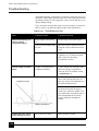
Troubleshooting . . . . . . . . . . . . . . . . . . . . . . . . . . . . . . . . . . . . . . . . . . . . .
Auto TEM (Wizard) Software . . . . . . . . . . . . . . . . . . . . . . . . . . . . . . . . . .
Introduction. . . . . . . . . . . . . . . . . . . . . . . . . . . . . . . . . . . . . . . . . . . . . . .
Samples. . . . . . . . . . . . . . . . . . . . . . . . . . . . . . . . . . . . . . . . . . . . . . . . . .
Auto TEM Interface . . . . . . . . . . . . . . . . . . . . . . . . . . . . . . . . . . . . . . . .
Milling Steps. . . . . . . . . . . . . . . . . . . . . . . . . . . . . . . . . . . . . . . . . . . . . .
Image Recognition . . . . . . . . . . . . . . . . . . . . . . . . . . . . . . . . . . . . . . . . .
Sample Definition Process . . . . . . . . . . . . . . . . . . . . . . . . . . . . . . . . . . . . .
Eucentric Height . . . . . . . . . . . . . . . . . . . . . . . . . . . . . . . . . . . . . . . . . . .
Running Auto TEM . . . . . . . . . . . . . . . . . . . . . . . . . . . . . . . . . . . . . . . .
Membrane Setup. . . . . . . . . . . . . . . . . . . . . . . . . . . . . . . . . . . . . . . . . . .
Sample Milling . . . . . . . . . . . . . . . . . . . . . . . . . . . . . . . . . . . . . . . . . . . . . .
Running the Data File from RunScript. . . . . . . . . . . . . . . . . . . . . . . . . .
Running the Data File from AutoFIB. . . . . . . . . . . . . . . . . . . . . . . . . . .
Sample Files . . . . . . . . . . . . . . . . . . . . . . . . . . . . . . . . . . . . . . . . . . . . . . . .
Script Variables. . . . . . . . . . . . . . . . . . . . . . . . . . . . . . . . . . . . . . . . . . . . . .
Initial Use . . . . . . . . . . . . . . . . . . . . . . . . . . . . . . . . . . . . . . . . . . . . . . . . . .
Troubleshooting . . . . . . . . . . . . . . . . . . . . . . . . . . . . . . . . . . . . . . . . . . . . .
Selective Etch Software . . . . . . . . . . . . . . . . . . . . . . . . . . . . . . . . . . . . . . .
How Selective Etch works . . . . . . . . . . . . . . . . . . . . . . . . . . . . . . . . . . .
Sample Holders . . . . . . . . . . . . . . . . . . . . . . . . . . . . . . . . . . . . . . . . . . . . . .
Sample Vise . . . . . . . . . . . . . . . . . . . . . . . . . . . . . . . . . . . . . . . . . . . . . .
Chapter 9
8-33
8-34
8-34
8-35
8-35
8-35
8-38
8-39
8-40
8-40
8-40
8-45
8-45
8-47
8-49
8-51
8-55
8-58
8-60
8-60
8-61
8-61
ALIGNMENTS
Overview. . . . . . . . . . . . . . . . . . . . . . . . . . . . . . . . . . . . . . . . . . . . . . . . . . 9-1
General description and structure . . . . . . . . . . . . . . . . . . . . . . . . . . . . . . . 9-1
Electron Column Alignment . . . . . . . . . . . . . . . . . . . . . . . . . . . . . . . . . . . . . 9-3
Alignment procedures. . . . . . . . . . . . . . . . . . . . . . . . . . . . . . . . . . . . . . . . 9-3
Final Lens Aperture Strip . . . . . . . . . . . . . . . . . . . . . . . . . . . . . . . . . . . . . 9-3
E-Column Alignments for Supervisors . . . . . . . . . . . . . . . . . . . . . . . . . . 9-3
Electron-Column Alignment Overview . . . . . . . . . . . . . . . . . . . . . . . . . . . . 9-4
Supervisors only . . . . . . . . . . . . . . . . . . . . . . . . . . . . . . . . . . . . . . . . . . . . 9-4
FEI Trained Supervisors /FEI Service . . . . . . . . . . . . . . . . . . . . . . . . . . . 9-5
Users (all) . . . . . . . . . . . . . . . . . . . . . . . . . . . . . . . . . . . . . . . . . . . . . . . . . 9-5
Tips for X and Y Corrective Movement. . . . . . . . . . . . . . . . . . . . . . . . . . 9-6
E-Column Aperture Alignment. . . . . . . . . . . . . . . . . . . . . . . . . . . . . . . . . . . 9-7
Recommended Apertures . . . . . . . . . . . . . . . . . . . . . . . . . . . . . . . . . . . . . 9-7
Aperture Loading Guidelines . . . . . . . . . . . . . . . . . . . . . . . . . . . . . . . . . . 9-7
Changing Final Lens Aperture Sizes . . . . . . . . . . . . . . . . . . . . . . . . . . . . 9-8
Strip Aperture Alignment Procedure . . . . . . . . . . . . . . . . . . . . . . . . . . . . 9-9
E-Column Alignment Procedures . . . . . . . . . . . . . . . . . . . . . . . . . . . . . . . . 9-10
4022 262 52351/02
Supervisor SEM Alignments . . . . . . . . . . . . . . . . . . . . . . . . . . . . . . . . . 9-10
10 - Source Tilt and Shift . . . . . . . . . . . . . . . . . . . . . . . . . . . . . . . . . . . . . . .9-11
Alignment Function . . . . . . . . . . . . . . . . . . . . . . . . . . . . . . . . . . . . . . . . 9-11
10 - Source Tilt and Shift Procedure . . . . . . . . . . . . . . . . . . . . . . . . . . . 9-11
44 - UHR Lens Alignment . . . . . . . . . . . . . . . . . . . . . . . . . . . . . . . . . . . . . .9-13
Alignment Function . . . . . . . . . . . . . . . . . . . . . . . . . . . . . . . . . . . . . . . . 9-13
44 UHR Lens Alignment Procedure . . . . . . . . . . . . . . . . . . . . . . . . . . . 9-13
42 - UHR Stigmator Alignment . . . . . . . . . . . . . . . . . . . . . . . . . . . . . . . . . .9-16
Alignment Function . . . . . . . . . . . . . . . . . . . . . . . . . . . . . . . . . . . . . . . . 9-16
42 UHR Stigmator Alignment Procedure . . . . . . . . . . . . . . . . . . . . . . . 9-16
43 - UHR Image Shift Correction . . . . . . . . . . . . . . . . . . . . . . . . . . . . . . . .9-19
Alignment Function . . . . . . . . . . . . . . . . . . . . . . . . . . . . . . . . . . . . . . . . 9-19
43 UHR Image Shift Correction Procedure . . . . . . . . . . . . . . . . . . . . . . 9-19
45 - HR Image Shift Correction . . . . . . . . . . . . . . . . . . . . . . . . . . . . . . . . . .9-22
Alignment Function . . . . . . . . . . . . . . . . . . . . . . . . . . . . . . . . . . . . . . . . 9-22
45 HR Image Shift Correction . . . . . . . . . . . . . . . . . . . . . . . . . . . . . . . . 9-22
11 - Automated Source Alignment. . . . . . . . . . . . . . . . . . . . . . . . . . . . . . . .9-24
Alignment Function . . . . . . . . . . . . . . . . . . . . . . . . . . . . . . . . . . . . . . . . 9-24
29 - Auto Zero detector . . . . . . . . . . . . . . . . . . . . . . . . . . . . . . . . . . . . . . . .9-26
Alignment Function . . . . . . . . . . . . . . . . . . . . . . . . . . . . . . . . . . . . . . . . 9-26
29 Auto Zero detectors procedure . . . . . . . . . . . . . . . . . . . . . . . . . . . . . 9-26
5 - Emitter Startup . . . . . . . . . . . . . . . . . . . . . . . . . . . . . . . . . . . . . . . . . . . .9-27
5 Emitter Startup Procedure . . . . . . . . . . . . . . . . . . . . . . . . . . . . . . . . . . 9-27
13 - Stigmator Alignment. . . . . . . . . . . . . . . . . . . . . . . . . . . . . . . . . . . . . . .9-29
User SEM Alignment. . . . . . . . . . . . . . . . . . . . . . . . . . . . . . . . . . . . . . . 9-29
13 Stigmator Alignment. . . . . . . . . . . . . . . . . . . . . . . . . . . . . . . . . . . . . 9-29
17 - Stage Rotation Center . . . . . . . . . . . . . . . . . . . . . . . . . . . . . . . . . . . . . .9-31
User SEM Alignment. . . . . . . . . . . . . . . . . . . . . . . . . . . . . . . . . . . . . . . 9-31
17 Stage Rotation Center procedure . . . . . . . . . . . . . . . . . . . . . . . . . . . 9-31
Ion-Column Alignment Overview . . . . . . . . . . . . . . . . . . . . . . . . . . . . . . . .9-33
Supervisors only. . . . . . . . . . . . . . . . . . . . . . . . . . . . . . . . . . . . . . . . . . . 9-33
100 - Vacuum. Startup IGP’s . . . . . . . . . . . . . . . . . . . . . . . . . . . . . . . . . . . .9-34
Alignment Field Functions. . . . . . . . . . . . . . . . . . . . . . . . . . . . . . . . . . . 9-34
100 Vacuum. Start IGP’s procedure . . . . . . . . . . . . . . . . . . . . . . . . . . . 9-34
210 - Ion Column Alignment . . . . . . . . . . . . . . . . . . . . . . . . . . . . . . . . . . . .9-35
Alignment Field Functions. . . . . . . . . . . . . . . . . . . . . . . . . . . . . . . . . . . 9-35
Alignment procedure . . . . . . . . . . . . . . . . . . . . . . . . . . . . . . . . . . . . . . . 9-38
Image shift Correction . . . . . . . . . . . . . . . . . . . . . . . . . . . . . . . . . . . . . . 9-41
253 - Supervisor: Ion Beam . . . . . . . . . . . . . . . . . . . . . . . . . . . . . . . . . . . . .9-42
Alignment Field Functions. . . . . . . . . . . . . . . . . . . . . . . . . . . . . . . . . . . 9-42
253 Supervisor: Ion Beam procedure . . . . . . . . . . . . . . . . . . . . . . . . . . 9-42
4022 262 52351/02
254 - Supervisor: GIS . . . . . . . . . . . . . . . . . . . . . . . . . . . . . . . . . . . . . . . . . 9-43
254 Supervisor: IGP procedure . . . . . . . . . . . . . . . . . . . . . . . . . . . . . . . 9-43
4022 262 52351/02
List of Figures
SAFETY & HANDLING 1
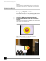
EMO BUTTON . . . . . . . . . . . . . . . . . . . . . . . . . . . . . . . . . . . . . . . . . . . . . . .1-6
EMO BUTTON LOCATION . . . . . . . . . . . . . . . . . . . . . . . . . . . . . . . . . . . . .1-6
SYSTEM OVERVIEW 2
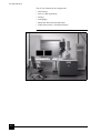
xT NOVA NANOLAB 200 SYSTEM . . . . . . . . . . . . . . . . . . . . . . . . . . . . . .2-2
SYSTEM OPERATION 3
START-UP DIALOG . . . . . . . . . . . . . . . . . . . . . . . . . . . . . . . . . . . . . . . . . . .3-3
SPLASH SCREEN FOR NOVA NANOLAB . . . . . . . . . . . . . . . . . . . . . . . .3-4
MINIMIZED SERVER DIALOG . . . . . . . . . . . . . . . . . . . . . . . . . . . . . . . . . .3-4
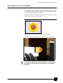
EMO BUTTON . . . . . . . . . . . . . . . . . . . . . . . . . . . . . . . . . . . . . . . . . . . . . .3-13
EMO BUTTON ON BACK OF THE E2 CONSOLE . . . . . . . . . . . . . . . . .3-13
USER INTERFACE 4
PREFERENCES TABS. . . . . . . . . . . . . . . . . . . . . . . . . . . . . . . . . . . . . . . . . .4-5
ON-LINE DOCUMENTATION. . . . . . . . . . . . . . . . . . . . . . . . . . . . . . . . . . .4-6
THE MAIN WINDOW . . . . . . . . . . . . . . . . . . . . . . . . . . . . . . . . . . . . . . . . .4-8
THE TITLE BAR . . . . . . . . . . . . . . . . . . . . . . . . . . . . . . . . . . . . . . . . . . . . .4-10
THE MENU BAR . . . . . . . . . . . . . . . . . . . . . . . . . . . . . . . . . . . . . . . . . . . . .4-10
FILE IMPORT / EXPORT MENU . . . . . . . . . . . . . . . . . . . . . . . . . . . . . . . .4-11
PRINTER DIALOG . . . . . . . . . . . . . . . . . . . . . . . . . . . . . . . . . . . . . . . . . . .4-12
SEM APERTURE SELECTION . . . . . . . . . . . . . . . . . . . . . . . . . . . . . . . . .4-18
SEM MODE SELECTION . . . . . . . . . . . . . . . . . . . . . . . . . . . . . . . . . . . . . .4-19
ICONS FOR LINKING Z TO FWD . . . . . . . . . . . . . . . . . . . . . . . . . . . . . . .4-22
DATABAR PREFERENCES . . . . . . . . . . . . . . . . . . . . . . . . . . . . . . . . . . . .4-30
UNITS PREFERENCES . . . . . . . . . . . . . . . . . . . . . . . . . . . . . . . . . . . . . . .4-31
PRESETS PREFERENCES . . . . . . . . . . . . . . . . . . . . . . . . . . . . . . . . . . . . .4-32
SCANNING PREFERENCES . . . . . . . . . . . . . . . . . . . . . . . . . . . . . . . . . . .4-33
GENERAL PREFERENCES . . . . . . . . . . . . . . . . . . . . . . . . . . . . . . . . . . . .4-35
THE MOVIE TAB DIALOGUE . . . . . . . . . . . . . . . . . . . . . . . . . . . . . . . . .4-37
THE SENSITIVITY TAB DIALOGUE . . . . . . . . . . . . . . . . . . . . . . . . . . . .4-37
THE TOOL BAR. . . . . . . . . . . . . . . . . . . . . . . . . . . . . . . . . . . . . . . . . . . . . .4-38
THE DATA BAR . . . . . . . . . . . . . . . . . . . . . . . . . . . . . . . . . . . . . . . . . . . . .4-42
COLUMN ICON LOGOS . . . . . . . . . . . . . . . . . . . . . . . . . . . . . . . . . . . . . . .4-45
TABBED COORDINATES DISPLAY . . . . . . . . . . . . . . . . . . . . . . . . . . . .4-50
PATTERN SELECTION CONTROLS. . . . . . . . . . . . . . . . . . . . . . . . . . . . .4-52
PATTERN PROPERTIES CONTROL . . . . . . . . . . . . . . . . . . . . . . . . . . . . .4-53
GAS INJECTOR OVERVIEW / DETAILS . . . . . . . . . . . . . . . . . . . . . . . .4-54
4022 262 52351/02
EPM Options . . . . . . . . . . . . . . . . . . . . . . . . . . . . . . . . . . . . . . . . . . . . . . . . 4-55
EPM SCALING . . . . . . . . . . . . . . . . . . . . . . . . . . . . . . . . . . . . . . . . . . . . . . 4-55
MEASUREMENT FUNCTION ACTIVE . . . . . . . . . . . . . . . . . . . . . . . . . . 4-56
ANNOTATION FUNCTION ACTIVE . . . . . . . . . . . . . . . . . . . . . . . . . . . . 4-57
ENHANCED IMAGE MIX FUNCTIONS . . . . . . . . . . . . . . . . . . . . . . . . . 4-58
PATTERN SELECTION CONTROLS . . . . . . . . . . . . . . . . . . . . . . . . . . . . 4-61
PATTERN PROPERTIES CONTROL . . . . . . . . . . . . . . . . . . . . . . . . . . . . 4-62
GAS INJECTOR OVERVIEW / DETAILS . . . . . . . . . . . . . . . . . . . . . . . . 4-62
WORKING WITH NOVA NANOLAB 5
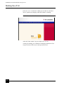
STARTUP XT SPLASH SCREEN . . . . . . . . . . . . . . . . . . . . . . . . . . . . . . . . 5-2
RELATIONSHIP OF THE TWO COLUMNS . . . . . . . . . . . . . . . . . . . . . . . 5-6
REQUIRED MATERIALS . . . . . . . . . . . . . . . . . . . . . . . . . . . . . . . . . . . . . 5-10
CLAMP THE ROW HOLDER ON THE TABLE . . . . . . . . . . . . . . . . . . . . 5-10
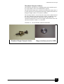
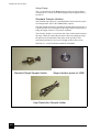
TEM SAMPLE / TEM SAMPLE MOUNTED . . . . . . . . . . . . . . . . . . . . . . 5-11
USE OF THE HAND CLAMP. . . . . . . . . . . . . . . . . . . . . . . . . . . . . . . . . . . 5-11
UMB HOLDER WITH MULTI-STUB MODULE . . . . . . . . . . . . . . . . . . . 5-12
OPTIONS FOR THE UMB HOLDER KIT . . . . . . . . . . . . . . . . . . . . . . . . . 5-12
RELATION BETWEEN VIEWED IMAGE AND STAGE . . . . . . . . . . . . 5-13
BEAM INDICATORS . . . . . . . . . . . . . . . . . . . . . . . . . . . . . . . . . . . . . . . . . 5-16
ETD DETECTION CHOICE . . . . . . . . . . . . . . . . . . . . . . . . . . . . . . . . . . . . 5-17
ETD CUSTOM MODE . . . . . . . . . . . . . . . . . . . . . . . . . . . . . . . . . . . . . . . . 5-17
MODE 1 & 3 TLD CHOICES . . . . . . . . . . . . . . . . . . . . . . . . . . . . . . . . . . . 5-18
MODE 2 TLD CHOICES . . . . . . . . . . . . . . . . . . . . . . . . . . . . . . . . . . . . . . . 5-18
CDEM DETECTION CHOICE . . . . . . . . . . . . . . . . . . . . . . . . . . . . . . . . . . 5-19
THE STEM DETECTOR . . . . . . . . . . . . . . . . . . . . . . . . . . . . . . . . . . . . . . 5-20
STEM DETECTOR CHOICES . . . . . . . . . . . . . . . . . . . . . . . . . . . . . . . . . . 5-21
STEM DETECTOR CHOICES. . . . . . . . . . . . . . . . . . . . . . . . . . . . . . . . . . 5-24
ACB DIALOG BOX. . . . . . . . . . . . . . . . . . . . . . . . . . . . . . . . . . . . . . . . . . . 5-26
AUTO FOCUS DIALOGUE BOX . . . . . . . . . . . . . . . . . . . . . . . . . . . . . . . 5-28
AUTO STIGMATOR DIALOGUE BOX . . . . . . . . . . . . . . . . . . . . . . . . . . 5-30
HV RELATED BEAM CURRENT VALUES . . . . . . . . . . . . . . . . . . . . . . 5-31
THE HEATED APERTURE HOLDER MODULE . . . . . . . . . . . . . . . . . . 5-32
MAGNIFICATION PRINCIPLE. . . . . . . . . . . . . . . . . . . . . . . . . . . . . . . . . 5-36
SNAPSHOT SETUP. . . . . . . . . . . . . . . . . . . . . . . . . . . . . . . . . . . . . . . . . . . 5-39
SAVE AS... DIALOG . . . . . . . . . . . . . . . . . . . . . . . . . . . . . . . . . . . . . . . . . 5-42
THE MOVIE TAB DIALOGUE . . . . . . . . . . . . . . . . . . . . . . . . . . . . . . . . . 5-44
FEI MOVIE CREATOR TAB: FILE . . . . . . . . . . . . . . . . . . . . . . . . . . . . . . 5-49
BROWSE DIALOGUE . . . . . . . . . . . . . . . . . . . . . . . . . . . . . . . . . . . . . . . . 5-49
MOVIE CREATOR TAB:DATABAR . . . . . . . . . . . . . . . . . . . . . . . . . . . . 5-51
MOVIE CREATOR TAB: PREVIEW . . . . . . . . . . . . . . . . . . . . . . . . . . . . . 5-52
4022 262 52351/02
PRINTER SETUP DIALOG . . . . . . . . . . . . . . . . . . . . . . . . . . . . . . . . . . . . .5-53
IMPORT OPEN DIALOG. . . . . . . . . . . . . . . . . . . . . . . . . . . . . . . . . . . . . . .5-54
EXPORT SAVE AS...DIALOG . . . . . . . . . . . . . . . . . . . . . . . . . . . . . . . . . .5-54
PATTERN SELECTION . . . . . . . . . . . . . . . . . . . . . . . . . . . . . . . . . . . . . . .5-59
RESIZING HANDLES / PATTERNING CURSORS . . . . . . . . . . . . . . . . .5-59
REORDERING PATTERNS . . . . . . . . . . . . . . . . . . . . . . . . . . . . . . . . . . . .5-62
APPLICATION FILES CHOICE . . . . . . . . . . . . . . . . . . . . . . . . . . . . . . . . .5-63
GAS INJECTOR OVERVIEW / DETAILS . . . . . . . . . . . . . . . . . . . . . . . .5-69
EPM OPTIONS . . . . . . . . . . . . . . . . . . . . . . . . . . . . . . . . . . . . . . . . . . . . . . .5-71
EPM SCALING. . . . . . . . . . . . . . . . . . . . . . . . . . . . . . . . . . . . . . . . . . . . . . .5-72
WITH AND WITHOUT BLACKOUT. . . . . . . . . . . . . . . . . . . . . . . . . . . . .5-75
BEAM COINCIDENCE . . . . . . . . . . . . . . . . . . . . . . . . . . . . . . . . . . . . . . . .5-76
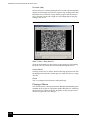
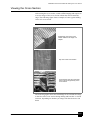
A TYPICAL CROSS SECTION . . . . . . . . . . . . . . . . . . . . . . . . . . . . . . . . . .5-80
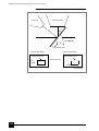
CROSS SECTION VIEWS . . . . . . . . . . . . . . . . . . . . . . . . . . . . . . . . . . . . .5-83
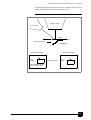
CROSS SECTION VIEWING DURING MILLING . . . . . . . . . . . . . . . . . .5-84
CROSS SECTION VIEWING AT 0° TILT . . . . . . . . . . . . . . . . . . . . . . . . .5-85
VIEWING AT 0° TILT ROTATED 180° . . . . . . . . . . . . . . . . . . . . . . . . . . .5-86
CONTROLS FOR MEASUREMENT . . . . . . . . . . . . . . . . . . . . . . . . . . . . .5-87
CONTROLS FOR ANNOTATIONS . . . . . . . . . . . . . . . . . . . . . . . . . . . . . .5-89
RESIZING HANDLES / GRAPHIC CURSORS . . . . . . . . . . . . . . . . . . . . .5-91
FEI ACCOUNT ADMINISTRATORS OVERVIEW . . . . . . . . . . . . . . . . .5-92
STAGES 6
NANOLAB 200 STAGE MANUAL CONTROLS . . . . . . . . . . . . . . . . . . . .6-2
NANOLAB 200 STAGE MOVEMENT . . . . . . . . . . . . . . . . . . . . . . . . . . . .6-3
NANOLAB 200 EUCENTRIC ADJUSTER . . . . . . . . . . . . . . . . . . . . . . . . .6-4
200 STANDARD SAMPLE HOLDERS . . . . . . . . . . . . . . . . . . . . . . . . . . . .6-5
NANOLAB 600 STAGE . . . . . . . . . . . . . . . . . . . . . . . . . . . . . . . . . . . . . . . .6-6
NANOLAB 600 STAGE MOVEMENT . . . . . . . . . . . . . . . . . . . . . . . . . . . .6-7
600 STANDARD SAMPLE HOLDERS . . . . . . . . . . . . . . . . . . . . . . . . . . . .6-8
UNDERSTANDING EUCENTRIC HEIGHT . . . . . . . . . . . . . . . . . . . . . . . .6-9
IMPORT DIALOG . . . . . . . . . . . . . . . . . . . . . . . . . . . . . . . . . . . . . . . . . . . .6-13
EXPORT DIALOG . . . . . . . . . . . . . . . . . . . . . . . . . . . . . . . . . . . . . . . . . . . .6-13
MAP ELEMENTS. . . . . . . . . . . . . . . . . . . . . . . . . . . . . . . . . . . . . . . . . . . . .6-14
MAP MAGNIFICATION (ZOOM) . . . . . . . . . . . . . . . . . . . . . . . . . . . . . . .6-16
TRACK FUNCTION . . . . . . . . . . . . . . . . . . . . . . . . . . . . . . . . . . . . . . . . . .6-20
GET FUNCTION . . . . . . . . . . . . . . . . . . . . . . . . . . . . . . . . . . . . . . . . . . . . .6-21
ARROW KEYS FOR STAGE FRAME SHIFT . . . . . . . . . . . . . . . . . . . . . .6-21
XT ALIGN FEATURE . . . . . . . . . . . . . . . . . . . . . . . . . . . . . . . . . . . . . . . . .6-22
COMPUCENTRIC ROTATION . . . . . . . . . . . . . . . . . . . . . . . . . . . . . . . . .6-24
SCAN ROTATION . . . . . . . . . . . . . . . . . . . . . . . . . . . . . . . . . . . . . . . . . . .6-29
4022 262 52351/02
SCAN ROTATION FROM THE BEAM PAGE . . . . . . . . . . . . . . . . . . . . . 6-30
MAINTENANCE 7
ELECTRON COLUMN APERTURE MODULE . . . . . . . . . . . . . . . . . . . . . 7-2
HARD & SOFTWARE OPTIONS 8
AUTOFIB WINDOW . . . . . . . . . . . . . . . . . . . . . . . . . . . . . . . . . . . . . . . . . . 8-3
DRIFT CONTROL DEFAULTS . . . . . . . . . . . . . . . . . . . . . . . . . . . . . . . . . . 8-7
BEAM SHIFT CALIBRATION . . . . . . . . . . . . . . . . . . . . . . . . . . . . . . . . . . 8-10
DYNAMIC DRIFT CONTROL MENU BAR . . . . . . . . . . . . . . . . . . . . . . . 8-10
SCRIPTING DIALOG BOX . . . . . . . . . . . . . . . . . . . . . . . . . . . . . . . . . . . . 8-11
SCRIPTING PARAMETERS . . . . . . . . . . . . . . . . . . . . . . . . . . . . . . . . . . . 8-12
AUTO SLICE & VIEW PROCESS STEPS . . . . . . . . . . . . . . . . . . . . . . . . . 8-21
AUTO SLICE AND VIEW MOVIE . . . . . . . . . . . . . . . . . . . . . . . . . . . . . . 8-32
TEM SAMPLE PREPARATION PROCESS . . . . . . . . . . . . . . . . . . . . . . . 8-34
PROTECTIVE LAYER ON LIFTOUT SAMPLES . . . . . . . . . . . . . . . . . . 8-36
ROUGH MILLING . . . . . . . . . . . . . . . . . . . . . . . . . . . . . . . . . . . . . . . . . . . 8-36
CUTOUT . . . . . . . . . . . . . . . . . . . . . . . . . . . . . . . . . . . . . . . . . . . . . . . . . . . 8-36
MEDIUM MILLING . . . . . . . . . . . . . . . . . . . . . . . . . . . . . . . . . . . . . . . . . . 8-37
FINE MILLING. . . . . . . . . . . . . . . . . . . . . . . . . . . . . . . . . . . . . . . . . . . . . . . 8-37
FINE POLISHING . . . . . . . . . . . . . . . . . . . . . . . . . . . . . . . . . . . . . . . . . . . . 8-37
MEMBRANE DEFINITION PROCESS . . . . . . . . . . . . . . . . . . . . . . . . . . . 8-39
REPRESENTATION OF TEM MEMBRANE
AND IMAGE RECOGNITION CROSSES . . . . . . . . . . . . . . . . . . . . . . . . . 8-41
X PAD DEPOSITION . . . . . . . . . . . . . . . . . . . . . . . . . . . . . . . . . . . . . . . . . 8-42
MEMBRANE POSITIONING . . . . . . . . . . . . . . . . . . . . . . . . . . . . . . . . . . . 8-42
GROUNDING LAYERS . . . . . . . . . . . . . . . . . . . . . . . . . . . . . . . . . . . . . . . 8-44
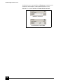
MEMBRANE MILLING PROCESS USING RUNSCRIPTS . . . . . . . . . . . 8-45
DATA1.INI FILE . . . . . . . . . . . . . . . . . . . . . . . . . . . . . . . . . . . . . . . . . . . . . 8-46
LIFTOUT SAMPLES VIEWED AT 7° . . . . . . . . . . . . . . . . . . . . . . . . . . . . 8-47
RUN AUTOFIB . . . . . . . . . . . . . . . . . . . . . . . . . . . . . . . . . . . . . . . . . . . . . . 8-47
AUTOFIB SCRIPTING DIALOG BOX . . . . . . . . . . . . . . . . . . . . . . . . . . . 8-48
PGA VISE . . . . . . . . . . . . . . . . . . . . . . . . . . . . . . . . . . . . . . . . . . . . . . . . . . 8-61
ALIGNMENTS 9
THE HEATED APERTURE HOLDER MODULE . . . . . . . . . . . . . . . . . . . . 9-7
FINAL LENS APERTURE CONTROL . . . . . . . . . . . . . . . . . . . . . . . . . . . . . 9-8
4022 262 52351/02
List of Tables
SAFETY & HANDLING 1
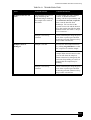
DC POWER WIRE CODING . . . . . . . . . . . . . . . . . . . . . . . . . . . . . . . . . . . . 1-5
AC CABLE CODING . . . . . . . . . . . . . . . . . . . . . . . . . . . . . . . . . . . . . . . . . . 1-5
SYSTEM OVERVIEW 2
SYSTEM OPERATION 3
LEAVING THE SYSTEM OVERNIGHT . . . . . . . . . . . . . . . . . . . . . . . . . . . 3-5
RETURNING TO OPERATION . . . . . . . . . . . . . . . . . . . . . . . . . . . . . . . . . . 3-6
GOING INTO STANDBY MODE . . . . . . . . . . . . . . . . . . . . . . . . . . . . . . . . . 3-7
STARTUP AFTER STANDBY . . . . . . . . . . . . . . . . . . . . . . . . . . . . . . . . . . . 3-8
COMPLETE SHUTDOWN PROCEDURE. . . . . . . . . . . . . . . . . . . . . . . . . 3-10
STARTUP FOR OPERATION . . . . . . . . . . . . . . . . . . . . . . . . . . . . . . . . . . . 3-11
USER INTERFACE 4
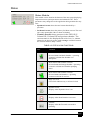
MENUS. . . . . . . . . . . . . . . . . . . . . . . . . . . . . . . . . . . . . . . . . . . . . . . . . . . . . 4-10
TABBED PREFERENCES. . . . . . . . . . . . . . . . . . . . . . . . . . . . . . . . . . . . . . 4-29
DATABAR STATUS. . . . . . . . . . . . . . . . . . . . . . . . . . . . . . . . . . . . . . . . . . . 4-42
PAGES . . . . . . . . . . . . . . . . . . . . . . . . . . . . . . . . . . . . . . . . . . . . . . . . . . . . . 4-43
STATUS ICON FUNCTIONS . . . . . . . . . . . . . . . . . . . . . . . . . . . . . . . . . . . 4-65
MOUSE BUTTON FUNCTIONS . . . . . . . . . . . . . . . . . . . . . . . . . . . . . . . . 4-67
DEDICATED WINDOWS kEYS. . . . . . . . . . . . . . . . . . . . . . . . . . . . . . . . . 4-68
FUNCTION KEY SHORTCUTS . . . . . . . . . . . . . . . . . . . . . . . . . . . . . . . . . 4-69
SPECIFIC KEY SHORTCUTS . . . . . . . . . . . . . . . . . . . . . . . . . . . . . . . . . . 4-70
PATTERNING SHORTCUTS . . . . . . . . . . . . . . . . . . . . . . . . . . . . . . . . . . . 4-72
MUI SOFTWARE CONTROL EQUIVALENTS. . . . . . . . . . . . . . . . . . . . . 4-73
WORKING WITH NOVA NANOLAB 5
XT STARTUP CONDITIONS . . . . . . . . . . . . . . . . . . . . . . . . . . . . . . . . . . . . 5-3
NOVA NANOLAB SETUP CONDITIONS . . . . . . . . . . . . . . . . . . . . . . . . . 5-4
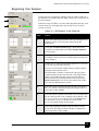
BEGINNING YOUR SESSION. . . . . . . . . . . . . . . . . . . . . . . . . . . . . . . . . . . 5-5
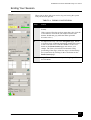
ENDING YOUR SESSION . . . . . . . . . . . . . . . . . . . . . . . . . . . . . . . . . . . . . . 5-7
EXCHANGING A SAMPLE . . . . . . . . . . . . . . . . . . . . . . . . . . . . . . . . . . . . . 5-9
OBTAINING AN IMAGE . . . . . . . . . . . . . . . . . . . . . . . . . . . . . . . . . . . . . . 5-14
DETECTOR MODES. . . . . . . . . . . . . . . . . . . . . . . . . . . . . . . . . . . . . . . . . . 5-15
CDEM DETECTOR RANGE CONDITIONS . . . . . . . . . . . . . . . . . . . . . . . 5-19
STEM DETECTOR POSITIONS. . . . . . . . . . . . . . . . . . . . . . . . . . . . . . . . . 5-21
C & B OPERATION . . . . . . . . . . . . . . . . . . . . . . . . . . . . . . . . . . . . . . . . . . . 5-25
CORRECTING C & B . . . . . . . . . . . . . . . . . . . . . . . . . . . . . . . . . . . . . . . . . 5-26
4022 262 52351/02
CORRECTING FOCUS WITH THE MOUSE . . . . . . . . . . . . . . . . . . . . . . 5-27
MOUSE CORRECTED ASTIGMATISM . . . . . . . . . . . . . . . . . . . . . . . . . . 5-29
STIGMATING WITH THE MUI . . . . . . . . . . . . . . . . . . . . . . . . . . . . . . . . . 5-30
DEFAULT FACTORY APERTURE SIZES . . . . . . . . . . . . . . . . . . . . . . . . . 5-32
ALIGNING THE FINAL LENS APERTURE . . . . . . . . . . . . . . . . . . . . . . . 5-33
GENERAL OPTIMAL I-BEAM CURRENTS . . . . . . . . . . . . . . . . . . . . . . 5-34
SPECIFIC OPTIMAL I-BEAM CURRENTS . . . . . . . . . . . . . . . . . . . . . . . 5-34
USING MOUSE WHEEL MAGNIFICATION . . . . . . . . . . . . . . . . . . . . . . 5-37
USING SNAPSHOT FOR IMAGE CAPTURE . . . . . . . . . . . . . . . . . . . . . . 5-40
USING PHOTO FOR IMAGE CAPTURE . . . . . . . . . . . . . . . . . . . . . . . . . 5-41
SET-UP AND RECORDING A MOVIE . . . . . . . . . . . . . . . . . . . . . . . . . . . 5-47
IMAGE PRINTING PROCEDURE . . . . . . . . . . . . . . . . . . . . . . . . . . . . . . . 5-53
PATTERN TOOL FUNCTIONS . . . . . . . . . . . . . . . . . . . . . . . . . . . . . . . . . 5-56
COLOR SETTINGS . . . . . . . . . . . . . . . . . . . . . . . . . . . . . . . . . . . . . . . . . . . 5-57
SILICON APPLICATION FILE (NON-GAS) . . . . . . . . . . . . . . . . . . . . . . . 5-63
SILICON APPLICATION FILE (GAS) . . . . . . . . . . . . . . . . . . . . . . . . . . . . 5-64
MATERIAL SPUTTER RATES AT 30 kV . . . . . . . . . . . . . . . . . . . . . . . . . 5-65
PATTERNING FILE BASIC PROPERTIES . . . . . . . . . . . . . . . . . . . . . . . . 5-66
PATTERNING FILE ADVANCED PROPERTIES . . . . . . . . . . . . . . . . . . . 5-66
SETTING UP THE GIS . . . . . . . . . . . . . . . . . . . . . . . . . . . . . . . . . . . . . . . . 5-70
SETTING UP THE EPM . . . . . . . . . . . . . . . . . . . . . . . . . . . . . . . . . . . . . . . 5-72
MILLING A PATTERN . . . . . . . . . . . . . . . . . . . . . . . . . . . . . . . . . . . . . . . . 5-77
BEAM CURRENTS/MILLING TIMES BY APPLICATION. . . . . . . . . . . 5-78
MILLING A SPOT . . . . . . . . . . . . . . . . . . . . . . . . . . . . . . . . . . . . . . . . . . . . 5-79
MAKING THE FIRST CROSS SECTION . . . . . . . . . . . . . . . . . . . . . . . . . 5-81
MAKING THE SECOND CUT (OPTIONAL) . . . . . . . . . . . . . . . . . . . . . . 5-82
MAKING THE FINAL CUT . . . . . . . . . . . . . . . . . . . . . . . . . . . . . . . . . . . . 5-82
USING MEASUREMENT FUNCTIONS . . . . . . . . . . . . . . . . . . . . . . . . . . 5-88
USING ANNOTATIONS FUNCTIONS . . . . . . . . . . . . . . . . . . . . . . . . . . . 5-90
STAGES 6
FINDING EUCENTRIC HEIGHT MANUALLY . . . . . . . . . . . . . . . . . . . . 6-10
ALIGNING BOTH BEAMS . . . . . . . . . . . . . . . . . . . . . . . . . . . . . . . . . . . . 6-10
MAP ELEMENT FUNCTIONS. . . . . . . . . . . . . . . . . . . . . . . . . . . . . . . . . . 6-14
SETTING ALIGN FEATURE . . . . . . . . . . . . . . . . . . . . . . . . . . . . . . . . . . . 6-23
DEFINE USER UNITS . . . . . . . . . . . . . . . . . . . . . . . . . . . . . . . . . . . . . . . . 6-25
ALIGNMENT TYPE DIFFERENCES . . . . . . . . . . . . . . . . . . . . . . . . . . . . 6-28
MAINTENANCE 7
4022 262 52351/02
HARD & SOFTWARE OPTIONS 8
AUTOFIB MODES. . . . . . . . . . . . . . . . . . . . . . . . . . . . . . . . . . . . . . . . . . . . . 8-3
FILE MENU OVERVIEW . . . . . . . . . . . . . . . . . . . . . . . . . . . . . . . . . . . . . . . 8-4
PLAY MENU OVERVIEW . . . . . . . . . . . . . . . . . . . . . . . . . . . . . . . . . . . . . . 8-4
LOGGING MENU OVERVIEW . . . . . . . . . . . . . . . . . . . . . . . . . . . . . . . . . . 8-5
OPTIONS MENU OVERVIEW . . . . . . . . . . . . . . . . . . . . . . . . . . . . . . . . . . . 8-6
SET-UP MENU OVERVIEW . . . . . . . . . . . . . . . . . . . . . . . . . . . . . . . . . . . . . 8-7
DRIFT CONTROL DEFAULTS DIALOG BOX . . . . . . . . . . . . . . . . . . . . . . 8-8
SCRIPTING PARAMETER SETTINGS . . . . . . . . . . . . . . . . . . . . . . . . . . . 8-12
LOG MESSAGES. . . . . . . . . . . . . . . . . . . . . . . . . . . . . . . . . . . . . . . . . . . . . 8-16
ERROR MESSAGES . . . . . . . . . . . . . . . . . . . . . . . . . . . . . . . . . . . . . . . . . . 8-17
FILE MENU COMMANDS . . . . . . . . . . . . . . . . . . . . . . . . . . . . . . . . . . . . . 8-23
SETUP MENU COMMANDS . . . . . . . . . . . . . . . . . . . . . . . . . . . . . . . . . . . 8-23
UTILITIES MENU COMMAND . . . . . . . . . . . . . . . . . . . . . . . . . . . . . . . . . 8-25
VIEW MENU COMMAND . . . . . . . . . . . . . . . . . . . . . . . . . . . . . . . . . . . . . 8-25
HELP MENU COMMANDS . . . . . . . . . . . . . . . . . . . . . . . . . . . . . . . . . . . . 8-25
AUTO S&V USER INTERFACE. . . . . . . . . . . . . . . . . . . . . . . . . . . . . . . . . 8-26
AUTO S&V TROUBLESHOOTING. . . . . . . . . . . . . . . . . . . . . . . . . . . . . . 8-33
LOCATION PARAMETERS . . . . . . . . . . . . . . . . . . . . . . . . . . . . . . . . . . . . 8-41
LIFTOUT PARAMETERS . . . . . . . . . . . . . . . . . . . . . . . . . . . . . . . . . . . . . . 8-43
RECIPE FILE PARAMETERS. . . . . . . . . . . . . . . . . . . . . . . . . . . . . . . . . . . 8-51
TROUBLESHOOTING . . . . . . . . . . . . . . . . . . . . . . . . . . . . . . . . . . . . . . . . 8-58
ALIGNMENTS 9
E-COLUMN ALIGNMENT ALLOCATION. . . . . . . . . . . . . . . . . . . . . . . . . 9-4
E-COLUMN ALIGNMENT ALLOCATION. . . . . . . . . . . . . . . . . . . . . . . . . 9-5
E-COLUMN ALIGNMENT ALLOCATION. . . . . . . . . . . . . . . . . . . . . . . . . 9-5
COMMON FIELD FUNCTIONS. . . . . . . . . . . . . . . . . . . . . . . . . . . . . . . . . . 9-6
GUIDELINES FOR APERTURES SIZES AND THEIR USES . . . . . . . . . . 9-7
ALIGNING THE FINAL LENS APERTURE . . . . . . . . . . . . . . . . . . . . . . . . 9-9
SUPERVISOR E-COLUMN ALIGNMENTS . . . . . . . . . . . . . . . . . . . . . . . 9-10
10 NO STEP . . . . . . . . . . . . . . . . . . . . . . . . . . . . . . . . . . . . . . . . . . . . . . . . . 9-11
10 STEP 1 OF 5 . . . . . . . . . . . . . . . . . . . . . . . . . . . . . . . . . . . . . . . . . . . . . . 9-11
10 STEPS 2 TO 5 . . . . . . . . . . . . . . . . . . . . . . . . . . . . . . . . . . . . . . . . . . . . . 9-12
44 NO STEP . . . . . . . . . . . . . . . . . . . . . . . . . . . . . . . . . . . . . . . . . . . . . . . . . 9-13
44 STEP 1 OF 5 . . . . . . . . . . . . . . . . . . . . . . . . . . . . . . . . . . . . . . . . . . . . . . 9-13
44 STEP 2 OF 5 . . . . . . . . . . . . . . . . . . . . . . . . . . . . . . . . . . . . . . . . . . . . . . 9-14
44 STEP 3 OF 5 . . . . . . . . . . . . . . . . . . . . . . . . . . . . . . . . . . . . . . . . . . . . . . 9-14
44 STEP 4 OF 5 . . . . . . . . . . . . . . . . . . . . . . . . . . . . . . . . . . . . . . . . . . . . . . 9-15
44 STEP 5 OF 5 . . . . . . . . . . . . . . . . . . . . . . . . . . . . . . . . . . . . . . . . . . . . . . 9-15
42 NO STEP . . . . . . . . . . . . . . . . . . . . . . . . . . . . . . . . . . . . . . . . . . . . . . . . . 9-16
4022 262 52351/02
42 STEP 1 OF 6 . . . . . . . . . . . . . . . . . . . . . . . . . . . . . . . . . . . . . . . . . . . . . .
42 STEP 2 OF 6 . . . . . . . . . . . . . . . . . . . . . . . . . . . . . . . . . . . . . . . . . . . . . .
42 STEPS 3 and 4 OF 6 . . . . . . . . . . . . . . . . . . . . . . . . . . . . . . . . . . . . . . . .
42 STEP 5 OF 6 . . . . . . . . . . . . . . . . . . . . . . . . . . . . . . . . . . . . . . . . . . . . . .
42 STEP 6 OF 6 . . . . . . . . . . . . . . . . . . . . . . . . . . . . . . . . . . . . . . . . . . . . . .
43 NO STEP . . . . . . . . . . . . . . . . . . . . . . . . . . . . . . . . . . . . . . . . . . . . . . . . .
43 STEP 1 OF 5 . . . . . . . . . . . . . . . . . . . . . . . . . . . . . . . . . . . . . . . . . . . . . .
43 STEP 2 OF 5 . . . . . . . . . . . . . . . . . . . . . . . . . . . . . . . . . . . . . . . . . . . . . .
43 STEP 3 TO 5 . . . . . . . . . . . . . . . . . . . . . . . . . . . . . . . . . . . . . . . . . . . . . .
43 STEP 4 OF 5 . . . . . . . . . . . . . . . . . . . . . . . . . . . . . . . . . . . . . . . . . . . . . .
43 STEP 5 OF 5 . . . . . . . . . . . . . . . . . . . . . . . . . . . . . . . . . . . . . . . . . . . . . .
45 NO STEP . . . . . . . . . . . . . . . . . . . . . . . . . . . . . . . . . . . . . . . . . . . . . . . . .
45 STEP 1 OF 3 . . . . . . . . . . . . . . . . . . . . . . . . . . . . . . . . . . . . . . . . . . . . . .
45 STEPS 2 TO 3 . . . . . . . . . . . . . . . . . . . . . . . . . . . . . . . . . . . . . . . . . . . . .
29 NO STEP TO 1 OF 1. . . . . . . . . . . . . . . . . . . . . . . . . . . . . . . . . . . . . . . .
5 NO STEP . . . . . . . . . . . . . . . . . . . . . . . . . . . . . . . . . . . . . . . . . . . . . . . . . .
5 STEP 1 OF 2 . . . . . . . . . . . . . . . . . . . . . . . . . . . . . . . . . . . . . . . . . . . . . . .
5 STEP 2 OF 2 . . . . . . . . . . . . . . . . . . . . . . . . . . . . . . . . . . . . . . . . . . . . . . .
FIELD NAME AND STATUS . . . . . . . . . . . . . . . . . . . . . . . . . . . . . . . . . . .
13 NO STEP . . . . . . . . . . . . . . . . . . . . . . . . . . . . . . . . . . . . . . . . . . . . . . . . .
13 STEP 1 OF 2 . . . . . . . . . . . . . . . . . . . . . . . . . . . . . . . . . . . . . . . . . . . . . .
13 STEP 2 OF 2 . . . . . . . . . . . . . . . . . . . . . . . . . . . . . . . . . . . . . . . . . . . . . .
17 NO STEP . . . . . . . . . . . . . . . . . . . . . . . . . . . . . . . . . . . . . . . . . . . . . . . . .
17 STEP 1 OF 3 . . . . . . . . . . . . . . . . . . . . . . . . . . . . . . . . . . . . . . . . . . . . . .
17 STEP 2 OF 3 . . . . . . . . . . . . . . . . . . . . . . . . . . . . . . . . . . . . . . . . . . . . . .
17 STEP 3 OF 3 . . . . . . . . . . . . . . . . . . . . . . . . . . . . . . . . . . . . . . . . . . . . . .
I-COLUMN ALIGNMENT ALLOCATION . . . . . . . . . . . . . . . . . . . . . . . .
100 FIELD FUNCTIONS STEP 0 to 1 . . . . . . . . . . . . . . . . . . . . . . . . . . . .
100 NO STEP TO 1 OF 1. . . . . . . . . . . . . . . . . . . . . . . . . . . . . . . . . . . . . . .
210 FIELD FUNCTIONS STEP 0 to 1 . . . . . . . . . . . . . . . . . . . . . . . . . . . .
210 FIELD FUNCTIONS STEP 2 . . . . . . . . . . . . . . . . . . . . . . . . . . . . . . . .
210 STIG & FOCUS CORRECTION (part 1). . . . . . . . . . . . . . . . . . . . . . .
210 STIG & FOCUS CORRECTION (part 2). . . . . . . . . . . . . . . . . . . . . . .
210 IMAGE SHIFT CORRECTION . . . . . . . . . . . . . . . . . . . . . . . . . . . . . .
253 FIELD FUNCTIONS STEP 0 to 1 . . . . . . . . . . . . . . . . . . . . . . . . . . . .
253 STEP 0 to 1 . . . . . . . . . . . . . . . . . . . . . . . . . . . . . . . . . . . . . . . . . . . . . .
254 FIELD FUNCTIONS . . . . . . . . . . . . . . . . . . . . . . . . . . . . . . . . . . . . . .
254 NO STEP TO 1 OF 1. . . . . . . . . . . . . . . . . . . . . . . . . . . . . . . . . . . . . . .
9-16
9-17
9-17
9-18
9-18
9-19
9-19
9-20
9-20
9-21
9-21
9-22
9-22
9-23
9-26
9-27
9-27
9-28
9-28
9-29
9-29
9-30
9-31
9-31
9-32
9-32
9-33
9-34
9-34
9-35
9-36
9-39
9-40
9-41
9-42
9-42
9-43
9-43
4022 262 52351/02
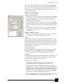
PREFACE
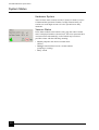
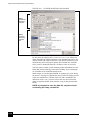
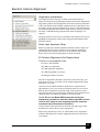
About this Manual
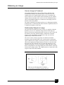
This User Manual for your Nova NanoLab is divided into the
following chapters:
•
1. SAFETY & HANDLING provides important information
required during operation and maintenance for product safety and
personal safety.
•
2. SYSTEM OVERVIEW gives the basics about your system’s
capabilities.
•
3. SYSTEM OPERATION gives procedures for several system
on/off modes, including Startup, Overnight Mode, and Emergency
Shutdown.
•
4. USER INTERFACE describes the interface that controls
system operation, giving the function of each Tool, Menu item and
Control Page.
•
5. WORKING WITH NOVA NANOLAB gives procedures of
how to use the system.
•
6. STAGES gives a full description of movement for each stage
and the software control.
•
7. MAINTENANCE step by step cleaning procedures.
•
8. HARD & SOFTWARE OPTIONS that are relevant options
integrated in or accessory to the Nova system.
•
9. ALIGNMENTS for the Electron and Ion columns that can be
performed by the Supervisor.
i
4022 262 52351/02
PREFACE
How to Use this Manual
How to Use this Manual
At the beginning is a main Contents, List of Figures and a List of
Tables covering the whole Manual. Each chapter has a Contents of the
subjects specific to that chapter. Included in some chapters are easyto-follow tables outlining task-oriented procedures. High-lighted text
can also be found in descriptive paragraphs to aid association of items
to graphics. On-line documentation is also available with the software
and can be activated from the Help menu or by clicking F1.
More explicit information on Safety issues can be found in
Chapter 1.
Conventions for Controls
References to specific knobs, buttons, labelled functions on the
system and in software are labelled in small capitals or highlighted
text. A sentence such as: “Click on the MEASUREMENT button to start
this function” refers to the software button itself.
Finding What You Need
This manual has been organized so you can find information in
several ways. You can read the manual from beginning to end (highly
recommended but rarely done). Be sure to read the safety section,
before operation, in Chapter 1.
Once your system is up and running, you can search for information
in the main contents or the individual contents proceeding each
chapter.
Major headings have been hung in the left column to help you scan for
the basics within a chapter. That column provides space for your own
notes as well.
Tables and Figures are numbered within each chapter and are listed
after the main Contents by chapter for the whole manual.
ii
4022 262 52351/02
1
SAFETY & HANDLING
Site Requirements
Verify that the safety and environmental requirements of the
workstation site, which are the responsibility of the customer, are
satisfied. In particular, the pump exhaust requirements, the electrical
supply and grounding (earthing) requirements, floor loading, and any
local codes regarding earthquake safety are important safety issues.
Electron Column Precautions
The Whole system conforms to:
•
EN61010-1 for Safety requirements for electrical equipment for
measurement, control and laboratory use.
•
X-ray emission below 1 µSv/h at 10 cm distance from the surface.
1-1
4022 262 52351/02
SAFETY & HANDLING Trained Service Personnel
Trained Service Personnel
Before starting any service task on an FEI Company product, such as
an electron microscope or ion beam equipment, or any related
accessories or third party equipment, the service engineer concerned
must first have read and understood the relevant sections of the FEI
Service Safety Manual.
The FEI Service Safety Manual, order code number 4022 190 50058,
contains explicit instructions on safe working methods, descriptions
of the various warning symbols and labels used on FEI equipment,
and Material Safety Data Sheets for all toxic gases and materials
which may be present.
A hardcopy of the FEI Service Safety Manual is shipped with every
FEI Company electron microscope or ion beam instrument, and it is
also present in electronic form on the FEI Customer Service CDROM.
WARNING! ONLY QUALIFIED FEI SERVICE ENGINEERS
SHOULD ATTEMPT TO PERFORM SERVICE
MAINTENANCE OR REPAIRS. OPENING ACCESS DOORS,
REMOVING SERVICE PANELS, AND OTHER
MAINTENANCE ACTIVITY CAN EXPOSE YOU TO
ELECTRICAL, CHEMICAL OR MECHANICAL HAZARDS,
COMPRESSED AIR, OR X-RAYS.
User Maintenance
CAUTION! Never attempt maintenance or service of any
kind on the electron column, other than that described for
the Supervisor, in this User Manual.
Allow only trained personnel to perform maintenance procedures.
Always observe appropriate safety practices in dealing with electronic
circuitry. Read and understand the safety precautions in this chapter
and throughout the manual. Observe industry-approved safety
methods and procedures.
If you have any doubt regarding approved safety procedures, contact
safety personnel at your company, or representatives of your state,
territory or province, or federal government.
1-2
4022 262 52351/02
SAFETY & HANDLING Terms and Symbols
Terms and Symbols
Symbols and messages
The following messages are used throughout FEI xT Nova manuals to
highlight information.
NOTE: Text of the note.....
A note emphasizes information requiring special attention.
CAUTION! Text of the caution....
A Caution message appears where special handling is required to
prevent product damage.
WARNING! TEXT OF THE WARNING...
A Warning message appears where special handling is required to
prevent personal injury or death.
DANGER! Text of the danger message....
A Danger message identifies an immediate personal risk of injury or
death and gives appropriate precautions.
The following signs may be visible on the instrumentation, avoid
contact with these points.
DANGER! High Voltage
Protective ground (earth) terminal
1-3
4022 262 52351/02
SAFETY & HANDLING Voltages
Voltages
According to the American National Standards Institute (ANSI)
guidelines, a shock hazard exists when voltage levels are present
which are 30 V rms or 42.4 V peak. Use extreme caution whenever a
shock hazard is present. As a good safety precaution, always expect a
hazardous voltage in an unknown circuit before measuring.
WARNING! COMPONENTS MAY HAVE POTENTIALLY
HIGH VOLTAGES (UP TO 30kV).
Operators and service personnel must be trained on potential safety
hazards and safe techniques, and must observe all warnings and
cautions encountered on the system and in the manuals. No person
should perform any operations without prior training.
Interlocks
Components include safety interlocks to minimize high voltage
hazards. Safety interlock circuitry is provided to protect system users.
Overriding interlocks is dangerous and should never be done by
untrained personnel.
After completing procedures for which an interlock was disconnected,
always reset (or reconnect) and test the interlock before proceeding.
Cover interlocks reset automatically when the covers are replaced.
Line Voltage
Line voltage (120 to 240 V AC) may be present in various locations
within the system, even when the system or instrument is turned off.
Completely disconnect the unit from line voltage by disconnecting the
AC plug from the AC power source before performing service or
maintenance.
WARNING! SERVICE AND TROUBLESHOOTING IN
THESE AREAS IS PERFORMED ONLY BY TRAINED FEI
SERVICE ENGINEERS.
Cords/Cables
Never connect or disconnect any cables or connections while power is
applied to the system or components. Doing so is potentially
hazardous to service personnel and could cause damage to the system
or its components.
DC Cable Colour-Coding System
Internal DC power wiring in the main console is colour-coded
according to Table 1-1.
1-4
4022 262 52351/02
SAFETY & HANDLING Voltages
TABLE 1-1 DC POWER WIRE CODING
Color
Voltage
Blue
0
Yellow
+5
Gray
+15
Lavender
-15
AC Cords
Plug the unit AC cords only into an approved power source. Use only
power cords that are in good condition. If replaced, use AC cords
rated to at least the rating of the original AC cord.
Each power cable is labelled with a destination and origin and are
colour-coded according to Table 1-2.
TABLE 1-2 AC CABLE CODING
North American
Color
International
Color
Solid Green
Green with Yellow
Stripe
Ground
Black
Brown
Line
White
Blue
Neutral
Meaning
Miscellaneous Cables
Check cables periodically for possible wear, cracks, or breaks. If any
defects are found, contact service personnel.
Main Power
The system main power should only be plugged into the approved
power receptacle, as identified by system documentation.
Ground (Earth)
Some components must be grounded to operate safely. Do not defeat
grounding or use an ungrounded power source. In the event of loss of
a protective ground connection, all accessible conductive parts
(including knobs and controls that may appear as insulating) can
render an electric shock.
Cover/Panels
Do not operate or plug in any electrical unit without the protective
covers or panels installed. Only qualified persons aware of the
electrical hazards should perform maintenance or service operations.
1-5
4022 262 52351/02
SAFETY & HANDLING Emergency Button
Fuses
Only trained service personnel should replace fuses. Replace fuses
only with fuses of the same type, voltage rating, and current rating.
Emergency Button
Emergency Off (EMO) Switches
In an emergency, press one of the large yellow and red EMO switches
to turn off all hazardous system voltages. The dry pump shuts down
and the specimen chamber vents, but the electron and ion columns
remain under vacuum.
CAUTION! A FEI Service Engineer or a Authorized
Supervisor must restart the system after an emergency
power off.
The EMO switches are latching. Once pushed in, they must be rotated
in the direction of the arrows to reset
FIGURE 1-1 EMO BUTTON
EMO switches are located on the back of the E2 Console
FIGURE 2 EMO BUTTON LOCATION
1-6
4022 262 52351/02
SAFETY & HANDLING Chemicals
Chemicals
Before using any chemicals, obtain and read a Material Safety Data
Sheet relating to the substance. Be aware of hazards and how to avoid
them, before using or handling any chemical.
Solvents
Use solvents carefully and in sparing quantities. Before using any
solvent, read the Material Safety Data Sheet. Avoid hazards listed on
the Material Safety literature, and avoid spillage, skin contact, eye
contact, and vapour inhalation.
WARNING! VOLATILE AND CORROSIVE SUBSTANCES
CAN DIFFUSE THROUGH CONTACT LENSES DESPITE
REASONABLY WELL VENTILATED CONDITIONS.
Moreover, contact lenses are difficult to remove when an irritant
chemical enters the eye, making irrigation ineffective. Care must be
taken to address the issue of contact lens worn by those coming into
contact with such solvent fumes.
Nitrogen
Nitrogen may be used to vent the system. Nitrogen is not poisonous,
but is a potential asphyxiant.
WARNING! SUFFOCATION IS POSSIBLE IF NITROGEN
OR LIQUID NITROGEN IS RELEASED IN AN ENCLOSED
ROOM WITHOUT ADEQUATE VENTILATION.
Liquid Nitrogen
Liquid nitrogen, used in the EDX system, has the potential to cause
frostbite if direct contact with skin occurs.
On standing, liquid nitrogen picks up oxygen from the air and forms
liquid oxygen in solution. Treat any liquid nitrogen that is not fresh as
though it had all the hazards of liquid oxygen.
1-7
4022 262 52351/02
SAFETY & HANDLING Miscellaneous Precautions
Miscellaneous Precautions
Electric Fans
Some instruments in the system may be air-cooled. Do not block the
air flow to or from the fans. Do not operate fans with the protective
covers or filters removed. Keep fingers, loose clothing, etc. away
from fans. Periodic filter maintenance may be required to prevent
overheating.
Pump Exhaust
Failure to provide proper exhaust filtering may discharge oil mist into
the environment. Such oil mist may be an environmental hazard as
well as a health hazard in an enclosed room.
Corrosion
Components are painted, plated, or otherwise treated to resist
corrosion. However, the components must be handled and stored
properly to prevent corrosion. Observe precautions carefully.
1-8
4022 262 52351/02
2
SYSTEM OVERVIEW
The Nova NanoLab integrates ion and electron beams for FIB and
SEM functionality in one machine. Users can switch between the two
beams for quick and accurate navigation and milling. Convergence of
the SEM and FIB at short working distance allows precision
“slice-and-view” cross-sectioning and analysis at high resolution.
The FIB is a Magnum™ ion column or Sidewinder™ ion column that
provides fast, precise milling and high-resolution images of the
sample surface.
The SEM column takes advantage of FEI’s most advanced
Hexalens™ design for ultimate image resolution at low beam
energies. It offers non destructive imaging capability at a working
distance optimized for ultra-high resolution and can produce images
magnified over 500 kx in mode 1 and greater than 2500 kx in mode 2.
Topographic data allows for monitoring of metal step coverage and
etch processes.
The xT Nova NanoLab 600 chamber, stage and wafer holder
accommodates wafers up to 6", or other devices, in a high-vacuum
environment. The high accuracy, five-axis stage provides computer
control and automation of all axes. The NanoLab 200 has a high
accuracy, five-axis stage, for smaller sample types, but also with
manual controls.
FEI’s Gas Injection Systems (GIS) use Enhanced Etch™ for fast
material removal with minimal redeposition, as well as metal
deposition and insulator deposition materials.
2-1
4022 262 52351/02
SYSTEM OVERVIEW
The xT Nova NanoLab was designed for:
• Data storage
• Process yield engineering
• Etching
• Lithography
• Metal and other materials deposition
• Fabrication of micro- and nanostructures
FIGURE 2-1 xT NOVA NANOLAB 200 SYSTEM
2-2
4022 262 52351/02
SYSTEM OVERVIEW FIB/SEM Capabilities
FIB/SEM Capabilities
FIB/SEM workstations provide an expanded range of capabilities not
possible with separate FIB and SEM tools:
• Electron beam high-resolution images of FIB cross sections
without eroding the feature of interest
• Real-time cross-section images with the electron beam during FIB
milling
• Focused electron beam charge neutralization during FIB milling
• Focused ion beam charge neutralization during SEM imaging
• High resolution elemental microanalysis of defect cross sections
• Image sample surface with the electron beam during navigation
without erosion or gallium implantation from the ion beam
• TEM sample preparation with in situ conductive coating
Control of the Beams
FIB/SEM workstations ideally position the point of interest for
simultaneous ion beam cross-sectioning and electron beam viewing.
Separate scan generators for the two beams permit coupled or
independent scan patterns and magnifications. Imaging while milling
aids in defining milled features.
Immediate electron beam images of cross sections are possible
without stage motion or sample transfer. Immediate high-resolution
SEM imaging after FIB milling also prevents exposure of milled cross
sections to atmospheric contaminants.
Gas Deposition
Multiple gas injectors can be installed for material deposition in
conjunction with either electron or ion beam pattern definition.
Electron beam-induced deposition offers the advantage of not
sputtering the deposited material or implanting gallium
simultaneously.
Gas Enhanced Etch
The Gas Injection System (GIS) also provides enhanced etching
capability for high aspect ratio drilling with minimal redeposition,
preferential etching of cross-section surfaces prior to SEM imaging,
and rapid milling of TEM sections.
Up to five GIS beam chemistries can be installed on the workstation,
depending on system configuration. This self-contained apparatus
allows the precursor material to be contained entirely within the
vacuum system for simple, flexible, and safe operation.
2-3
4022 262 52351/02
SYSTEM OVERVIEW FIB/SEM Capabilities
X-Ray Analysis Capability
Energy Dispersive X-ray (EDX) provides elemental analysis
capability for identification of surface and subsurface features.
Convergence of the SEM, FIB, and EDX at short working distance
allows precision “slice-and-view” cross-sectioning and chemical
analysis at high resolution. Various vendor options are compatible
with the workstation.
User Interface
The xT software interface integrates SEM and FIB functionality
within a Windows 2000™ or Windows XP™ operating environment.
The user interface consists of a single high-level user shell employing
applications programs with vector parameter files defining specific
instrument settings for particular applications ensuring reproducibility
of complex procedures.
An intermediate software layer, acting on instructions from the
application layer controls the column, detector(s), stage, EDX and
vacuum functions. This layer also provides management of image
capture, storage, and data output devices.
A Manual User Interface (MUI) offers additional flexibility for
controlling magnification, beam shift, focus, contrast and brightness,
and stigmation.
Computerized Stage
A computer-controlled, 5-axis stage offers fast, repeatable, and
precise sample manipulation. Two versions are available:
• 200 (50 x 50 mm)
• 600 (150 x 150 mm)
Optical Camera
A low-magnification optical image obtained with the Optical Camera
assists in overall spatial orientation on highly repetitive or extremely
irregular samples. It also aids in positioning gas injectors on packaged
IC parts or other non uniform samples.
Supervisor and User Log-on
The SUPERVISOR and all USER level accounts run under the same
Windows 2000 account, and are the only types of account available to
the customer under normal circumstances.
Refer to Chapter 3 for Start-up and Log-on/Log-off
2-4
4022 262 52351/02
SYSTEM OVERVIEW NanoLab Options
NanoLab Options
A range of hardware and software are available as options for xT
Nova NanoLab workstations. This range will be extended when new
items become available.
Some of the options are:
• Gas injectors
• Detectors:
CDEM
STEM 1
• FIB Software Options:
AutoFIB
Auto Slice & View
AutoTEM
• Sample holders:
UMB (Universal Mounting Base) sample holder set
Vise Holder
Wafer Holders
• EDX Software Options
• Image Analysis
• 3D Reconstruction Software
Contact your FEI sales representative for more up-to-date information
on system options.
2-5
4022 262 52351/02
SYSTEM OVERVIEW NanoLab Options
2-6
4022 262 52351/02
3
SYSTEM OPERATION
Nova NanoLab
Overview
FEI systems are started at the time of installation to obtain an
adequate high vacuum for the system and remain on unless there is a
power failure or some catastrophic event.
This chapter describes:
• System Status
• Log On/Log Off
• Leaving the system overnight
• Returning to operation
• Standby Mode
• Startup after Standby
• Complete System Shutdown
• Startup from Complete System Shutdown
• Emergency power off (EMO)
NOTE:
Before starting the workstation, check for the presence of:
• Electrical power
• Compressed air
• Cooling water
• Nitrogen for venting
With the exception of nitrogen, interlocks prevent the vacuum system
from operating if the others are not present.
3-1
4022 262 52351/02
SYSTEM OPERATION System Status
System Status
Hardware System
There are three main vacuum sections: E-Source/Column, I-source/
Column and the Specimen Chamber. In High Vacuum mode, all
sections are under high vacuum. All valve operations are fully
automatic.
Vacuum Status
In the Status module at the bottom of any page the actual vacuum
status is displayed with the coloured icon. This icon represents three
vacuum sections schematically, each of which may have three
possible colours with the following meaning:
• Green: pumped to the desired vacuum mode
(HiVac)
• Orange: transition between two vacuum statuses
(pumping or venting)
• Grey: vented
3-2
4022 262 52351/02
SYSTEM OPERATION Log-On / Log-Off
Log-On / Log-Off
Supervisor and User Log-On/Log-Off
First log-on under Windows 2000 as SUPERVISOR or USER, allow the
server and UI to load, then start the UI with a password. A default
password is allocated on installation to the Supervisor for the
Windows and UI Log-on.
When the status of the UI is ‘waiting’ for a new USER only the Server
state is active and the UI state non-active. Therefore changing the
USER does not require Log-Off / log-On at Windows 2000 level but
just Log-Off / Log-On at the UI level.
Launch Server level
When starting the Nova NanoLab operating program a progressive
dialog for Server and UI is displayed. The Server needs to be
launched first followed by the UI. Press the Start server button.
FIGURE 3-1 START-UP DIALOG
SERVER
PROGRESS
BAR
MODULE
OPERATION
DISPLAY
UI
PROGRESS
BAR
START
SERVER
START
UI
AUTORUN
UI
STOP
SERVER
STOP
UI
DISPLAY
ADVANCED
PAGE
3-3
4022 262 52351/02
SYSTEM OPERATION Log-On / Log-Off
Launch UI Level
When the Server is fully launched the Start UI button becomes active.
Click on the Start UI button and a Splash-screen appears during the UI
loading. This is then replaced by the UI.
FIGURE 3-2 SPLASH SCREEN FOR NOVA NANOLAB
Minimized Server dialog
The start-up dialog can be minimized once the UI is established by
clicking with the right mouse button in the top bar of the dialog. this
opens a further dialog that offers the chance to minimize the server to
the top bar of the UI.
FIGURE 3-3 MINIMIZED SERVER DIALOG
NOTE: The stage will need to be homed before full
operation of the UI is possible. A dialog will display in the
screen center for this purpose after the Log-on dialog has
closed. If it is not homed at the first displayed dialog it can
be homed by selecting Home Stage from the Stage Menu
later.
3-4
4022 262 52351/02
SYSTEM OPERATION Leaving the System Overnight
Leaving the System Overnight
Overnight and weekends
If you don’t plan to use the workstation until the following day or
weekend, use the SLEEP button facility on the Beam Control page.
This switches off the ion column source, but leaves the electron
column filament current on. Returning to full operation takes only a
few minutes.
TABLE 3-1 LEAVING THE SYSTEM OVERNIGHT
Step
Action
1
Click on the SLEEP button in the SYSTEM module to
switch off both beam simultaneously. The Ion
column source switches off completely. This is seen
by reduction in the SOURCE progress bar in the
column module when the Ion beam is selected.
The Electron column reduces to filament current on
only.
2
The Beam Control page will then indicate that the
system is ready to wake up via the WAKE UP button
in the SYSTEM module.
3
Click on STOP UI in the Server bar. This action will
also act as Log-off current user. Switch off the
monitor.
3-5
4022 262 52351/02
SYSTEM OPERATION Returning to operation
Returning to operation
Operation
This procedure is almost the previous in reverse.
TABLE 3-2 RETURNING TO OPERATION
3-6
Step
Action
1
Switch on the monitor. Click on the START UI button
on the Server bar. The UI splash dialog appears on
the screen followed by the UI.
2
Log-on the UI
3
Click on the WAKE UP button in the SYSTEM module
to switch on the Ion column sources completely.
This is seen by an increase in the SOURCE progress
bar in the column module when the Ion beam is
selected.
4
The Beam Control page will then indicate that the
system is ready and only the SLEEP button in the
SYSTEM module is active.
4022 262 52351/02
SYSTEM OPERATION Standby Mode
Standby Mode
Going into Standby Mode
Standby Mode is a system shutdown process used when the system
will not be used for several weeks or during service.
Standby mode is different from the system being completely turned
off and is used mostly by service personnel. In the standby mode, the
electronics racks are powerless except for the E-column source, Ecolumn, I column (IGP’s) vacuum pump and computer. All IGP’s are
still running but The TMP (Turbomolecular Pump) and roughing
pump shut down. The chamber is not vented by Nitrogen gas.
The system can be left in this state if utilities (water, air, nitrogen),
other than electrical, need to be disconnected.
TABLE 3-3 GOING INTO STANDBY MODE
Step
Action
1
In the Beam Control page, click the Sleep button to
switch off both beams. The Ebeam FEG source is
still running but the ion source and both HT’s will be
turned off.
2
Select tilt 0 (Ctrl+E) from the Stage menu..
3
Remove your sample if needed by the Load Lock.
4
Click Stop UI to stop the xT Microscope User
Interface. Double Click the Blue progress bar.
5
Click Stop to stop the server, , Wait until the xT
microscope server stops, then click the Standby
button on the front panel of the system..
6
Select YES in the dialog box, the system will go to
the Standby mode.
When Standby mode is selected, in order to recover from a failure, it
is better at that moment to restart the Microscope PC before restarting
the microscope.
3-7
4022 262 52351/02
SYSTEM OPERATION Startup After Standby
Startup After Standby
Startup
It is assumed here that all external supplies are present. The startup
procedure is fully automatic.
TABLE 3-4 STARTUP AFTER STANDBY
Step
Action
1
Press the Power ON/Standby button on the front
control panel of the microscope.
Open the microscope cabinet and press
microscope computer power ON/OFF button to
switch ON.
2
Start the software by clicking on the
FeiSystemControl icon to display the xT
Microscope Server dialog..
Click on the Start button. Click on the Advanced
button. Wait until the dialogue is fully functional (All
LEDs needs to be green).
3-8
3
Select Start UI. Once the microscope server has
started the Splash screen appears followed by the
xT User Interface dialog. Log-on is requested. Input
a user name and password to activate the
Microscope User Interface. Once logged-on leave
the stage home dialogue box unselected.
4
Click Pump in the Beam control page to pump the
Specimen chamber.
4022 262 52351/02
SYSTEM OPERATION Startup After Standby
TABLE 3-4 STARTUP AFTER STANDBY
Step
Action
5
Once the vacuum is ready, click Wake Up to start
the ion source if needed.
6
Select Yes in the Home Stage dialogue to home
the stage.
7
If a CDEM is installed in the system, go to the
Alignment page and select adjustment 29-Auto
Zero detectors to autocalibrate the CDEM.
8
The system is now ready to use.
NOTE: Wake Up not only starts the Ion source and HT but
also switches on the Electron Beam HT. if this is not
immediately required then it can be switched off in the EBeam page.
3-9
4022 262 52351/02
SYSTEM OPERATION Complete System Shutdown
Complete System Shutdown
Shutdown
Complete shutdown should be performed only if absolutely necessary
and for the shortest possible time, so as to recover the column vacuum
without the necessity of a system pump. Normally, one would only
perform a complete shutdown for transportation of the system or for
service actions, like repair to essential electrical and air supplies. The
shutdown procedure brings the system to a non-powered state, where
the vacuum in the Electron and Ion column area is no longer
supported by running pumps and IGPs. All valves are closed and the
specimen chamber is vented. This procedure should only be carried
out by a Supervisor.
NOTE: Do not use this mode unless you are positive that
you want to turn off the E-Beam source.
The emission characteristics of the source are dependent on the shape
of the tip. When the source is turned off, it cools. Reheating the source
during startup changes the shape and emission characteristics
dramatically, requiring the column to be aligned. It also reduces the
lifetime of the source.
TABLE 3-5 COMPLETE SHUTDOWN PROCEDURE
3-10
Step
Action
1
Set the system to Standby mode as described
above, then press and hold the front panel On/
Standby button for 5 second, then release the
button. The system will now be shut down
completely.
2
Shut down the microscope computer by Windows
software.
4022 262 52351/02
SYSTEM OPERATION Startup from complete System Shutdown
Startup from complete System Shutdown
Startup
The Startup procedure has to be followed when ever the system has
been shutdown for service or due to a power failure. After startup has
been initiated observe the system for the first 30 minutes to confirm
that the IGPs show sufficient vacuum to continue and complete the
procedure.
TABLE 3-6 STARTUP FOR OPERATION
Step
Action
1
Press the Power ON/Standby button on the front
control panel of the microscope.
Open the microscope cabinet and press the
microscope computer power ON/OFF button to ON.
2
Start the software by clicking on the
FeiSystemControl icon to display the xT
Microscope Server dialog..
Click on the Start button. Click on the Advanced
button. Wait until the dialogue is fully functional (All
LEDSs needs to be green).
3
Select Start UI. Once the microscope server has
started the Splash screen appears followed by the
xT User Interface dialog. Log-on is requested. Input
a user name and password to activate the
Microscope User Interface. Once logged-on leave
the stage home dialogue box unselected.
4
Once you logon to the user interface, you will find
that both the E Column IGP and I column IGP are
turned off and the pressures are unknown. To turn
on the IGPs, Go to the Alignment page, select 100Vacuum Start IGP’s, then follow the instructions.
3-11
4022 262 52351/02
SYSTEM OPERATION Startup from complete System Shutdown
TABLE 3-6 STARTUP FOR OPERATION
Step
Action
5
First press the IGPs on button under Electron
Column, wait for the Electron column IGP to start,
then press IGPs On under Ion Column to start the
ion column IGP. Once both the columns have
vacuum readings, click Finish to exit 100-Vacuum
Start IGP’s.
6
Click Pump in the Beam control page to pump the
Specimen chamber.
7
Once the vacuum is ready, click Wake Up to start
the ion source if needed.
8
Select Yes in the Home Stage dialogue to home the
stage.
9
If a CDEM is installed in the system, go to the
Alignment page and select adjustment 29-Auto
Zero detectors to autocalibricate the CDEM.
NOTE: When vacuum pressures are too high at point 5 in
the procedure for system operation then a bakeout is
required. If this is the case a trained FEI Service Engineer
or a FEI trained Supervisor must restart the system.
3-12
4022 262 52351/02
SYSTEM OPERATION Emergency Power Off (EMO)
Emergency Power Off (EMO)
In an emergency, press one of the large yellow and red EMO switches
to turn off all system hazardous voltages. The system will be brought
into a safe state, and turn of completely.
The EMO switches are latching. Once pushed in, they must be rotated
in the direction of the arrows to reset.
FIGURE 3-4 EMO BUTTON
EMO switches are located on the back of the E2 Console.
FIGURE 5 EMO BUTTON ON BACK OF THE E2 CONSOLE
CAUTION! A trained FEI Service Engineer or Authorized
Supervisor must restart the system after an emergency
power off.
3-13
4022 262 52351/02
SYSTEM OPERATION What Happens during Power Failures
What Happens during Power Failures
The system has protection against power failures in the sense that the
different components of the system are not likely to be damaged.
However, a power failure is never good for the system. It might affect
the ultra-high vacuum levels of the columns and the overall stability
of the system. Take sufficient measures to avoid power failures as
much as possible.
If a power failure occurs during normal operation of the workstation,
the system powers down to a safe status and the following happens:
• The specimen chamber vents.
• The column valves close so the high vacuum in the columns is not
completely lost.
• The momentary adjustments of all the workstation parameters
(high voltage, magnification, etc.) are lost if they have not been
saved prior to the failure.
If the system was down less than 45 minutes it can be recovered
according to the Startup procedure by an authorized supervisor. If the
system has been off for a longer time a FEI trained service engineer
may have to bring the workstation back into operation.
3-14
4022 262 52351/02
4
USER INTERFACE
This chapter gives an overview of the xT Control software for the
Nova NanoLab and describes the functionality of each part of the user
interface. It takes you from the first main window and menu bar
through each item on the pulldown menus through to the pages.
Graphics illustrating most of the choices help you locate specific
features.
The software interface controls most system functions including
milling, patterning, detection and analysis, scanning and
magnification, image gathering, manipulation and output, stage and
vacuum.
For more detailed information about Windows 2000, refer to the
Microsoft® Windows™ Users’ Guide shipped with your system.
Other Software and Hardware
Call Customer Service for advice before installing software or
hardware that is not required for system operation. Other software,
such as screen savers, or hardware network cards may corrupt the
system control software under some circumstances and may
invalidate warranty.
User Access Privileges
Multiple levels of user access are defined in the software. The user
has full access to the instrument, except for any alignments. The
supervisor has access to a set of supervisor alignments.
The pages found in this manual are Supervisor/User pages where the
users are permitted to control general operation functions and but not
advanced technical maintenance. Most technical maintenance is taken
care of by a FEI SEM/FIB trained service engineer who has the rights
to enter the system via a Service access level similar to the Factory
level entry.
4-1
4022 262 52351/02
USER INTERFACE Software Interface Elements
Software Interface Elements
Icon
A small symbol indicating a specific software application. For
example, the software can be shrunk to an icon at the bottom of the
screen. An application shown as an icon is running in the background
of the computer memory. Double-click on the icon to restore the
program.
There are also icons in the Tool bar for selecting system functions
quickly (as seen on the left). Clicking on any of these will cause them
to press in, when deactivated by clicking again they spring out.
Pulldown Menus
The microscope uses menu-oriented software; you perform functions
by choosing items from the Menu bar. The Menu bar selections
contain pulldown menus that display group listings of available
commands or settings. Some menu items are shown in gray and
cannot be selected. You might also get a beeping sound if you try to
select unavailable functions.
Selecting with the Mouse
To select a pulldown menu, click on the menu item in the Menu bar,
then drag the cursor down to the desired selection and release the left
mouse button.
Pulldown menu selections followed by points (...) indicate a dialog
box will display. Selections with a right arrow indicate an additional
submenu of choices will display.
If the selected setting is a parameter value, the new value is updated
immediately and a check mark appears in the pulldown menu. If the
selected setting is a command, a new popup menu or dialog box
appears.
Selecting with Keyboard Commands
To use keyboard commands for selecting top level menu items, press
ALT plus the underlined letter (for example, ALT + D for the Detector
menu), and then select from the choices with the left mouse button or
with the up or down arrow keys.
Dialog Boxes
A dialog box appears when the system needs more information from
you before it can carry out a command. You can input information
using text boxes, option buttons and command buttons.
Some dialog boxes do not let you access other functions until you exit
the box. Other dialog boxes let you perform other tasks while they
remain onscreen and active. For example, the Preferences dialog
boxes can remain open while you do other tasks.
4-2
4022 262 52351/02
USER INTERFACE Software Interface Elements
Radio Buttons
Use round option buttons to make selections. Within a group of
related option buttons, only one selection can be active at any time.
Check Boxes
Use square check boxes to make selections. Single or within a group
of check boxes, items can be switched on or off by clicking in the
individual boxes. A ‘tick’ means ‘ON’ or active and an empty box
means ‘OFF’ or inactive
Command Buttons
Rectangular command buttons carry out a function. They press in
when clicked on and some change colour to show activity. When
reversing the function the button springs out. Command buttons have
labels that describe the action. Examples: OK, CANCEL, APPLY, RESET
Click on OK to close the dialog box. The software updates all
information shown in the dialog box. Click on CANCEL to quit the
dialog box without updating the information. Click on APPLY to
introduce the change immediately, but not permanent. click on RESET
to restore default conditions.
List Boxes
List boxes contain available choices, such as Location settings. If a
list box is too small to show all the selections, click on the up or down
arrow in the vertical scroll bar or click and drag the slider to see more
of the list.
Property Editors
These are the same in structure as normal list boxes but text can be
entered in as part of the listing. The entry space is white and the
prohibited zones are shaded. The user should click in the VALUE side
of the relevant property editor and then either type in the new value or
select from the drop down list.
4-3
4022 262 52351/02
USER INTERFACE Software Interface Elements
Continuous Control Adjusters
A continuous control adjuster allows you to change parameters, such
as contrast and brightness, in a continuous way by clicking and
dragging the middle slider or clicking in the gray bar.
•
middle slider—for large or small adjustments. The further from
left the middle slider is pulled, the larger the change.
•
gray bar—for large adjustments, single step increments.
•
end arrow— fine step increments.
These adjusters always have a label in the upper left and right corners
for readout information.
Preset/Continuous Control Adjusters
This special control is used for values that have both a continuous
range and a list of presets, such as E-column HV. It is used on the
Beam Control page. The button on the left side of the adjuster
toggles between modes.
Two-Dimensional X-Y Controls
These two-dimensional continuous controls are represented by an XY box. The position of the crosshair is related to the actual settings,
the full range of the parameters being represented by the perimeter of
the box.
Ticked
4-4
Unticked
Click and hold down the left mouse button in the grid to display a
crosshair in the image area. The cursor changes to a 4 axis cross and
can be moved in four directions that correspond to the X, Y screen
values. To fix the values, release the mouse button and the position of
the crosshair updates.The sensitivity of the X-Y control can depend
on the magnification chosen. At higher magnification, you may click
on the center square with the right mouse button to open a dialog
showing a choice of Coarse, Fine, Zero, Clear Memory and Auto
Alignment. Zero will bring the 2D control to the center.
4022 262 52351/02
USER INTERFACE Software Interface Elements
Text Boxes
Type information in a text box. This direct keyboard input is used to
produce text such as filenames, passwords, user labels in the data bar,
and specified values of certain parameters.
Progress dialogs
Progress dialogs indicate progress of a procedure over time by means
of a progress bar.
Tabbed Dialogs
Tabbed dialogs form either across the operating page or in a Quad
(lower right). These can be alternately opened by clicking on the label
along the top of the dialog area. Preferences and other conditions can
be changed and stored in these dialogs.
FIGURE 4-1 PREFERENCES TABS
4-5
4022 262 52351/02
USER INTERFACE Help Functions
Help Functions
Tool-Tips
The first line help is integrated in the software as Tool-Tips. These
are activated when the cursor is left over a item on the user interface
for 2 seconds. A short explanation of the item will appear until the
cursor is moved away from the item.
On-Line Documentation
The On-Line Documentation function can be switched on by the F1
key on the keyboard or from the Help menu. The Help dialog area is
defaulted to the bottom right Quad at startup, and can be expanded to
all Quads for more detailed help including diagrams and images. It
can also be dragged to any position on the available screen. The help
box function remembers the position and size that the user last defined
until defaulted on startup.
Hyperlinked Help
The opened Help pages have hyperlinks to subjects such as operation
procedures, Tips and other useful information.
FIGURE 4-2 ON-LINE DOCUMENTATION.
Display controls
The On-line window can be placed in any quad or any half screen as
well as full screen. This can be controlled from the listed buttons on
the top right of the On-line window. These are useful if it is important
to view the application at the same time. The On-line window can also
be dragged to size and placed anywhere on the screen. The position of
the window is remembered when the On-line window is recalled.
4-6
4022 262 52351/02
USER INTERFACE xT Control Interface Elements
xT Control Interface Elements
The xT Control Interface Elements make up some or all of the
application windows displayed when the xT Control software is
loaded.
This consists of the following items:
• Main Window - displays all interface elements
• Title Bar - labels the application and the owner/user
• Menu Bar - contains all operation menus and submenus
• Preferences dialogs - presetting of operating conditions
• Tool Bar - contains all iconised button functions
• Pages - contains all pages made up of one or more modules
• Quad Image Windows - 4 image windows providing independent
image functionality modes
• Main Image Window - full single image mode
• Data Bar - contains all data information entered by preference for
storage/printout of the image.
Control of some or all of these items is made via the mouse, keyboard
or the Manual User Interface pad.
4-7
4022 262 52351/02
USER INTERFACE The Main Window
The Main Window
The Main Window displays status and control features for the
Microscope Control, including the image window, application bar,
menu bar, tool bar, data bar and pages.
FIGURE 4-3 THE MAIN WINDOW
1
1
Quad 1
2
4
6
Quad 2
5
Quad 3
Quad 4
3
4-8
4022 262 52351/02
USER INTERFACE The Main Window
Interface Elements
Some of the xT Control Interface main elements break down into
other sub-menus or modules.These consists of the following items:
1. The Title Bar - labels the application and the owner/user
2. The Menu Bar - contains all operation menus and submenus:
• The File Menu
• Edit Menu
• The Detector Menu
• The Scan Menu
• The Beam Menu
• The Patterning Menu
• The Stage Menu
• The Tools Menu
• The Window Menu
• The Help Menu
3. Preferences... - opens in 4th Quad for presetting of operating
conditions.
• DataBar
• Units
• Presets
• Scanning
• Magnification
• General
• Movie
• Sensitivity
4. The Tool Bar - contains all iconised button functions
5. The Data Bar - contains all data information entered by preference
for storage/printout of the image.
6. Pages and Modules - contains all pages made up of one or more
modules:
• Beam Control Page
• Navigation Page
• Patterning Page
• Processing Page
• Detector Page
• Sample Prep Page
• Alignments Page
7. Hardware Interface Elements (not shown here)
• Mouse
• Keyboard
• Manual User Interface (MUI) (Option)
• Joystick (Option)
4-9
4022 262 52351/02
USER INTERFACE The Title Bar
The Title Bar
The Title Bar displays the logged on user name that was entered to
log on Windows 2000 level.
FIGURE 4-4 THE TITLE BAR
The Menu Bar
The Menu Bar displays pulldown menus across the top of the screen
below the Title Bar.
FIGURE 4-5 THE MENU BAR
Menu Bar Functions
The following menus are available:
TABLE 4-1 MENUS
Menu Item
Use
File
Administrative functions.
Edit
Edit Pattern(s) such as delete or select all.
Detector
List of detectors.
Scan
Scan condition functions for Electron and
Ion beams.
Beam
Choice of Beam conditions; Electron, Ion
and Light, and controls.
Patterning
Patterning and deposition functions.
Stage
Stage navigation and corrective functions.
Tools
Image Auto functions.
Window
The image display functions.
Help
About Nova UI and On-line help.
Select pulldown menus from the menu bar by using either the left
mouse button or ALT + letter from the keyboard.
4-10
4022 262 52351/02
USER INTERFACE File Menu
File Menu
Clicking on the File name in the Menu bar, with the left mouse button,
opens the File menu. This can also be achieved by pressing the Alt+F
keys.
Open
Clicking on Open, with the left mouse button, opens a dialog for
opening an image in the selected quad or a full screen. Images can be
opened in TIF (8, 16 and 24 bit col or depth), JPG and Bitmap
formats.
Save
Clicking on Save, with the left mouse button, saves the image with an
incremental label at a predetermined location. This is also used when
a restored image has been updated in any way, such as a LUT change
and is necessary to overwrite the original. This can also be achieved
by pressing the Crtl +S keys.
Save As...
Clicking on Save As, with the left mouse button, opens a dialog for
saving an image. This provides an opportunity to change the label and
save the same file, a new file, with a different label.
Record Movie
Clicking on Record Movie starts the recording of three videos, one
for each of the three image quads at the same moment. If a quad is
paused when starting the video, only the first image with a time stamp
is stored. The red dot icon on the Tool Bar represents the same
function When Record Movie is active the icon changes to a red
square. Pressed it stops the movie function.
Import / Export
Access can be made to certain files produced by the FEI xT system.
This in turn leads to an import / export dialog for selection.
STG files (Stage Positions), PTF files (Patterns), EPM files (EndPoint Monitor Graphs) and parameters are available to Import /
Export. When opening the file, parameters or data saved with it are
restored.
FIGURE 4-6 FILE IMPORT / EXPORT MENU
4-11
4022 262 52351/02
USER INTERFACE File Menu
Print...
Clicking on Print, with the left mouse button, opens the printer dialog
so that choice of printer and conditions can be established ready to
print an image, or any other printable product from the microscope.
This can also be achieved by pressing the Ctrl + P keys. Pressing OK
in the printer dialog will activate the printer to print the job.
FIGURE 4-7 PRINTER DIALOG
Exit
Clicking on Exit, with the left mouse button, will exit the UI program
and leave one in the operating system environment with the Server
still running. This can also be achieved by pressing the Alt + X keys.
To activate the UI again one would have to click on Start UI in the
Server bar.
4-12
4022 262 52351/02
USER INTERFACE Edit Menu
Edit Menu
Clicking on the Edit name in the Menu bar, with the left mouse
button, opens the Edit menu. This can also be achieved by pressing
the Alt+E keys.
The Edit menu is for copying, cutting, pasting or deleting patterns.
There is also a select all function for multiple processing.
Copy
Copy an existing pattern.
Cut
Cut an existing pattern from one quad to paste in another.
Paste
Paste a pattern from memory into the existing quad or another.
Delete
Delete a pattern.
Select All
Select all patterns in a quad.
4-13
4022 262 52351/02
USER INTERFACE Detectors Menu
Detectors Menu
Clicking on the Detector name in the Menu bar, with the left mouse
button, opens the Detector menu. This can also be achieved by
pressing the Alt + D keys.
Detector list
This list contains various detectors for E-Beam and I-Beam operation.
Depending on the beam mode in operation only the relevant detectors
will appear in black. All others will be grayed out. Only the selected
detector will show a tick next to it’s label.
Customizing or choosing preferences for different detectors can be
found on the Detector Page.
4-14
4022 262 52351/02
USER INTERFACE Scan Menu
Scan Menu
Clicking with the left mouse button on the Scan name in the menu
bar, opens the scan menu. This can also be achieved by pressing the
Alt + C keys.
Pause
Click on the Pause function to pause the image. Click once and the
scan will stop immediately without finishing the frame. When Pause
is active clicking again will release the pause function and return the
scanning to the original condition prior to pause. The Pause icon
button on the Tool bar has the same functionality. It can also be
activated by F6.
Snapshot
Clicking on Snapshot at any time will activate a preset scan.The
result can be stored on the harddrive automatically to a predetermined
directory using the next available label/number (same as Save
destination). If the Save or Save As function is not set in Preferences
the image is only retained onscreen by the Pause function. Unpause to
start scanning. Snapshot can also be activated from the Tool Bar.
Snapshot for the Electron beam can be activated by function key F4.
Snapshot for the Ion beam can be activated by function key Crtl + F4.
Photo
Clicking on Photo at any time will activate a preset higher resolution
slow scan.The result can be stored on the harddrive with the Save
command, in the File menu, by using the next available label/number
in a predetermined folder. Save As can be used if the Folder and label
need to be changed prior to saving. Photo can also be activated by F2.
Videoscope
Videoscope toggles the display of the videoscope on or off, showing
the video intensity along the currently scanned horizontal line. It can
also be activated by F3.
Reduced area
When Reduced area is chosen, the reduced area appears with the
same dimensions and at the last known place on the screen. On
activation it restores the last used scan condition. Scan condition can
be changed if necessary. Can also be activated by F7.
Full Frame
Full Frame is the default scanning mode. This is the normal scanning
mode, typical for general navigation.
Spot
Clicking on Spot puts you in Spot mode and allows one to move the
beam around the screen with the left mouse button pressed. The spot
position is represented by a green cross.
4-15
4022 262 52351/02
USER INTERFACE Scan Menu
Line
When Line is selected from the Scan menu, the image freezes and a
green horizontal line displays on the screen. The beam scans along
this line, using the line time defined for the selected scan speed. When
you choose Line, the cursor changes to an arrow. Move the cursor to
the desired vertical position and click the left mouse button.
External
External is a switch to activate external control of the scanning
system, such as beam control from an EDX X-ray system.
Slow Scan
Clicking on Slow Scan will bring the scanning condition to the preset
value, held in the Preferences/Scan dialog.
Fast Scan
Clicking on Fast Scan will bring the scanning condition to the preset
value, held in the Preferences/Scan dialog.
Slower Scan
Clicking on Slower Scan will bring the scanning condition to the next
slower scan value held in the Preferences/Scan list dialog. This can be
also achieved by pressing Crtl + “,”.
Faster Scan
Clicking on Faster Scan will bring the scanning condition to the next
faster scan value held in the Preferences/Scan list dialog. This can be
also achieved by pressing Crtl + “.”.
Mains Lock
Clicking On Mains Lock will synchronize the mains frequency to the
Scan system.
Live
With Live selected, the image remains unfiltered for collecting direct
images, mostly in Live/Slow scan.
Average
Select Average to continuously average a specified number of
frames, selected from the list, resulting in a better signal-to-noise
ratio. This is used mostly in a fast scan mode to reduce noise in fast
scanned images. During averaging, the image is updated continuously
and actions such as focusing, moving the stage, etc. can still be
performed. The number of frames can be selected as a preset from the
Tool bar drop down list box associated with the Average function.
Integrate
The Integrate feature allows accumulative noise reduction by true
integration over a number of frames, selected from the list, and
freezes the final image. During and after image accumulation, you
cannot change the focus or perform other image-influencing actions.
The number of frames can be selected as a preset from the sub menu
or from the Tool bar drop down list box associated with the Integrate
function.
4-16
4022 262 52351/02
USER INTERFACE Scan Menu
Scan Rotation
Clicking on Scan Rotation activates the onscreen tool to rotate the
scan and align the image. It has no effect on the stage movements and
is solely a scan coil function but is used to orientate the image relative
to mechanical rotation and detector direction. It can also be activated
by Shift + F12.
Preferences...
Clicking on Preferences... opens the total preferences dialog. Scan
choices can be found under the tab labelled ‘Scan’.
4-17
4022 262 52351/02
USER INTERFACE Beam Menu
Beam Menu
Clicking on the Beam name in the Menu bar, with the left mouse
button, opens the Beam menu. This can also be achieved by pressing
the Alt button and the B key.
Electron Beam
Clicking on Electron Beam will make the Quad or single screen active to
the electron beam with respect to source, column, scanning, and detectors.
Ion Beam
Clicking on Ion Beam will make the Quad or single screen active to the
ion beam with respect to source, column, milling, scanning, and detectors.
Optical Beam
Clicking on Optical Beam will make the Quad or single screen active
to the optical beam with respect to Source, and detector.
Toggle E-I Beam
Clicking on Toggle E-I Beam will allow moving from one beam
operation to the other and visa-versa. This can also be achieved by
pressing Ctrl+T on the keyboard.
Couple Magnifications
Clicking on Couple Magnifications will allow the Electron and Ion
columns to be coupled together, so that when switching between columns
there is no difference in magnification.This is particularly useful when
milling with the Ion Beam and viewing with the Electron Beam.
SEM Aperture
The SEM column final aperture can be selected by clicking on SEM
Aperture in the Beam menu. A secondary dropdown menu appears
with a selection of aperture sizes. For correct correlation the aperture
selected in this menu should correspond to the physical SEM aperture
selected.
FIGURE 4-8 SEM APERTURE SELECTION
Home Apertures
Home Apertures sends the steppermotors of the FIB Aperture
Mechanism back to its home position.
4-18
4022 262 52351/02
USER INTERFACE Beam Menu
SEM Mode
By clicking on SEM Mode the following two modes of image
resolution are available for use with the E-Beam:
Mode 1 (Field Free)
Mode 2 (Immersion)
Mode 3 (EDX)
FIGURE 4-9 SEM MODE SELECTION
Either mode has its own E-Beam and magnification presets and are
editable in the Tool Bar dropdown list or the Preferences E-BEAM Tab.
Use the Tool Bar buttons to switch between modes.
Degauss (Electron Beam)
Degauss triggers the degauss procedure appropriate for the current
SEM Mode. The procedure puts all currently used electron lenses in a
normalized state by removing their hysteresis effects. For a few
seconds while the procedure is running all live images disappear or
turn fuzzy, and than returns back. Use this function with (almost)
focused image to obtain the most accurate Magnification, HFW and
Working Distance readouts.
Lens Alignment
This is dedicated to the electron column. Lens Alignment toggles lens
alignment mode on the Beam Page for the objective lens fine
alignment. The scanning condition changes to a fast scan, and the lens
modulator turns on, a green target cross appears in the center of all
SEM image Quads. Pressing and holding the left mouse button
activates a quad arrow ended cursor. Dragging the mouse aligns the
beam with respect to the objective lens with the purpose of reducing
the movement swing. This in turn eliminates or reduces the movement
during focusing.
Preferences...
Clicking on Preferences... opens the preferences dialog at the Beam
Tab.
4-19
4022 262 52351/02
USER INTERFACE Patterning Menu
Patterning Menu
This is the menu for executing Patterning.
These items in the Patterning Menu are command functions and
change according to the function operating at the present time. They
also follows the trend of the Tool Bar buttons and Pattern Page.
Start Patterning (in Quad #)
Click on Start Patterning to begin patterning with the pattern
selected on the Patterning Page. After the command will appear the
Quad number use for patterning and after that the status, such as
Pause. Click on Pause to temporarily stop patterning, click again to
Unpause and to continue.
Reset Patterning
Click on Reset Patterning to reset patterning to the beginning of the
pattern procedure once again. Press Ctrl+Pause
Next Pattern
Next Pattern will be available if multiple patterns have been drawn.
Click on Next Pattern to stop milling the current pattern and continue
with the next pattern. Also can be activated on the Pattern Page. Press
Shift+P.
Next Line
When the cleaning cross-section is used Next Line will be enabled.
Click on next line to stop milling the current line and continue with
the next line. Also can be activated on the Pattern Page. Press
Shift+N.
Previous Line
When the cleaning cross-section is used Previous Line will be
enabled. Click on next line to stop milling the current line and
continue with the next line. Also can be activated on the Pattern Page.
Press Ctrl+Shift+N.
Sleep After Patterning
Sleep After Patterning activates the Sleep command (from Beam
Control page) when the patterning process finishes.
Blackout Pattern Area for RTM
This function blacks out the pattern background where the RTM is
displayed. It is made black in order to enhance the visibility of the
RTM information.
Autostart Real Time Monitor
Click on Autostart Real Time Monitor for the RTM to
automatically start when patterning starts.
4-20
4022 262 52351/02
USER INTERFACE Stage Menu
Stage Menu
Clicking on the Stage name in the Menu bar, with the left mouse
button, opens the Stage menu. This can also be achieved by pressing
the Alt + S keys.
xT Align Feature...
Clicking on xT Align Feature starts a procedure that helps one to
orientate a linear feature to either of the stage movement directions; X
or Y.
Compucentric Rotation
Clicking on Compucentric Rotation in the Stage Menu places a
green circle in the active quad. By rotating the circle a different
viewing orientation of the sample area can be achieved. This is
compucentric stage rotation. It can also accessed by F12 or on the
Stage Page / Coordinates Tab.
Define User Units...
Clicking Define User Units on activates a series of dialogs that guide
the user to determine User Unit values for X and Y movements of the
stage. These are used in relative movements associated with stage
mapping of regular features, in particular in IC applications.
Offset Alignment
Offset Alignment is a shortcut that allows you to move to new points
relative to the existing alignment but at a new location, for example,
stepping between identical points on different dies quickly.
User Units
Clicking on User Units organises the stage software to recognise the
defined user units rather than the default metric measurements. The X
and Y coordinates now operate in User Units and is shown in the
Location module by the UU symbol.
Beam Shift Reset
Use this function to begin the Beam Shift Reset procedure to zero
beam shift and move the feature to the center of the field of view with
the stage.
Zero Beam Shift
When beam shift has reached maximum limits, choose Zero Beam
Shift to restore X and Y beam shifts to zero values. The computer
beeps when maximum limits are reached.
4-21
4022 262 52351/02
USER INTERFACE Stage Menu
Home Stage
Clicking on Home Stage will open a dialog to define the influential
conditions, and by pressing YES the Stage will home. When the stage
is homing the Stage Active dialog box flashes onscreen. When the
stage is homed correctly, the end position will be the last Reference
position stored.
Z = preset long working distance relative to stage type.
It can also accessed by Shift + F3 keys.
Home Apertures
Home Apertures sends the steppermotors of the FIB Aperture
Mechanism back to its home position.
Home Stage Without Rotation
This function is to perform Home Stage function without rotating of
the stage. When the stage is homed without rotation, the stage
reference for Rotation is greyed out. This is useful when a large
specimen is inserted and stage rotation could cause a collision with
equipment inside the chamber. By default the function is enabled and
automatically reverts back to the enabled status after every venting /
pumping cycle.
Center Position
Moves the stage to coordinates X = 0, Y = 0, which is the central
position.
Touch Alarm Enabled
This function automatically stops the stage movement and displays
Touch Alarm warning dialogue whenever the stage or a conductive
specimen touches the Immersion lens or any other equipment
conductively connected to the chamber.
UnLink Z to FWD
Clicking on Unlink to FWD will display height (z) as a value
corresponding with the distance from the z home position.
Link Z to FWD
Sets the Z coordinate value to actual Free Working Distance (FWD)
value. This allows accurate movement between the known height of
the sample and the end of the Immersion lens.
NOTE: The related toolbar icon image changes according to
the Z-coordinate status.
FIGURE 4-10 ICONS FOR LINKING Z TO FWD
Greyed icon: the function is disabled because either the stage has not
been homed or the HV is switched off (so there is no SEM image), or
the Ion Beam is selected.
Red question mark: the function is enabled and the link between Z
4-22
4022 262 52351/02
USER INTERFACE Stage Menu
and FWD is unknown. Use the function as soon as possible, after
properly focusing the image.
Red circle: Z is roughly linked to FWD, but it needs correction. The
function is enabled. It happens e.g. after: changing the specimen,
focusing and linking Z to FWD at a long Working Distance and then
moving the stage to a short WD. Focus image carefully at a WD
around 5 mm and use this function again.
Green double-ended arrow: Z is properly linked to FWD. Now it
should be safe to change the Working Distance by setting a Z
coordinate in the Stage module. The function is still enabled to allow
further corrections of the Z-coordinate.
Enable Z Tilt map
Some movements of the stage are illegal because of possible collision
with the end lens. In a z-tilt map, a number of z-tilt value pairs
indicate the maximum tilt angle for a certain z when coupled. A legal
move of the tilt axis depends on the position of the z axis. The relation
between the extreme positions of tilt and z indicate the extreme
allowed positions. This relation is called the z-tilt map and can be
used to guarantee safe usage of the stage.
Tilt 0° (Ctrl + E)
Tilt 52° (Ctrl + I)
Sets stage tilt to 0° / 52°, perpendicular to Electron / Ion Beam
respectively.
Sample Navigation
Toggles on / off function that enables to navigate live SEM images
(scan field) towards desired places on a specimen using either paused
or loaded image of that specimen (usually taken at much lower
magnification).
The Sample Navigation can be selected independently for any Quad,
regardless of its current content and status. A tick next to the menu
item indicates that the function is selected for the active Quad. As
soon as this Quad is paused, the Sample Navigation indicator appears
in the upper right corner of the Quad. The indicator is green as long as
the paused image can be used to navigate the live images, otherwise
turns read (e.g. when the stage rotation or tilt changes).
(See Chapter 5 for a detailed description.)
NOTE: To make sure this function working properly, the stage
rotation value for captured image and corresponding live
images are the same.
Preferences...
Clicking on Preferences... opens the preferences dialog.
4-23
4022 262 52351/02
USER INTERFACE Tools Menu
Tools Menu
Clicking on the Tools label in the Menu bar, with the left mouse
button, opens the Tools menu. This can also be achieved by pressing
the Alt + o keys.
Image Registration
With user-specified alignment points, the user can transform one
image spatially to correspond to another image, then mill on that new
image as if it were an image of the sample. The transformed image
could include one taken with the optical microscope that corresponds
to the real sample, or several taken at various depths of focus. This is
also called image-to-image registration and image alignment.
Click on Image Registration and follow the prompts in the dialog
box that appears. The user first selects the quad with the reference
image and then the quad with the target image (this is the one that will
be transformed). After this a single or multipoint alignment can be
applied by selecting similar points in both the reference and target
image. Register will apply the transformation after 1, 2 or 3 pairs of
points have been selected. See TABLE 6-7 (Alignment Type
Difference) for a description of when to apply each time of alignment.
Register will re-apply the registration on any new or restored image
in the same or a different quad. When Show is selected from the
overlay panel a copy of the registered target image will be shown on
the reference image which shows the quality of the registration and to
allow information from both images to be used in placing patterns.
The overlay can be shown in red, green or blue. The Threshold value
(0 to 255) determines which gray levels of the target image are shown
in the overlay.
After registration the micron bar and magnification of the target
image take on the same values of the reference image. Any operation
that is applicable to an acquired FIB/SEM image can be applied to a
transformed image, including creating and milling patterns and saving
to a file.
Tips on Using Image Registration
Additional considerations include the following:
• Use images of similar magnification. In general, magnification
needs to be as high as possible, with obvious limits for images
taken with the optical microscope.
• Select Quad-Image mode before beginning.
• Image alignment, particularly 3-pt, is error-sensitive. Use care in
selecting the corresponding features as precisely as possible.
• Use the crosshairs to make selections.
• Change to Single-Image mode for maximum enlargement while
selecting the features for alignment.
• Use alignment points as far apart as possible, such as at the outer
edges of the image.
• If possible, use points that are equidistant and orthogonal.
4-24
4022 262 52351/02
USER INTERFACE Tools Menu
• After alignment, mill or deposit on the imported image or on the
composite overlay image. Alternately, mill cross patterns briefly to
mark the positions of buried structures so they are readily apparent
during imaging.
Auto Contrast Brightness
Click on Auto Contrast Brightness to activate the automatic contrast
and brightness routine. Can also be activated by pressing F9, or the
Icon button on the Tool Bar.
Autofocus
Click on Autofocus to activate the automatic focus routine. Can also
be activated by pressing F11, or the Icon button on the Tool Bar.
Auto Lens \ Stigmator Alignment
Click on Auto lens\Stigmator Alignment to activate the automatic
Lens \ Stigmator correction routine.
Display Saturation
Click on Display Saturation to view the saturation status of the image.
Oversaturated areas of the image (white areas) are shown in blue and
undersaturated areas (black areas) are shown in yellow. Can also be
activated by pressing Shift + F11
Lab Notes
Opens the Windows NotePad application above Quad 4 for the user to
make immediate notes and remarks. After entry of a note the file can
be stored as a text file (.TXT). Any previous note can also be opened
in Lab Notes.
FEI Movie Creator
Provides a tabbed dialogue above Quad 4 for setting up a collection of
sequenced TIF images, and sequencing them into an AVI movie. See
Chapter 5 for a detailed description. This utility is installed also on the
support computer, which enables to create a movie without
influencing the microscope controller operation.
Application Status
Clicking on Application Status opens a dialog in the 4th Quad
displaying a continuously updating status of the system.
Preferences..
Clicking on Preferences.. displays the preferences dialog.
4-25
4022 262 52351/02
USER INTERFACE Window Menu
Window Menu
Clicking on the Window name in the Menu bar, with the left mouse
button, opens the Window menu. This can also be achieved by
pressing the Alt+W keys.
Center Cross
Clicking on Center Cross places a cross in the center of either the
single screen or each quad depending on the display mode selected.
This can also be achieved by pressing Shift+F5 keys. This function is
used in the Adjustment procedures to aid centering of features.
Alignment rectangle
Clicking on Alignment rectangle places a staggered rectangle in the
center of either the single screen or each quad depending on the
display mode selected. This can also be achieved by pressing
Shift+F6 keys. This function is used in the Adjustment procedures to
aid controlling illumination.
CCD Axis marker
Displays x, y, and z axis in the CCD quad.
CrossHair cursor
Clicking on Crosshair cursor changes the mouse cursor into a
crosshair cursor. The crosshair cursor is useful for aligning patterns or
features.
Redo digital zoom 1x, 2x, 4x, 8x
Digital zoom can be set from the Measurement and Annotation
Page by increasing or decreasing the magnification for the active
image/Quad. Redo digital zoom retains the last magnification factor
set by Digital zoom and when clicked on will set the magnification
factor in the active Quad to that stored.
Undo digital zoom
When the Redo digital zoom has been activated the label in the
Window menu reverts to Undo digital zoom. Clicking in Undo
digital zoom brings the image back to normal magnification by
negating the factor created by Digital zoom.
Single-Image / Quad-Image Mode
Single-Image / Quad-Image mode toggles the image display area
from a single screen to a quad screen and vice-versa. It can also be
activated by pressing F5.
In Single-image mode the quad list is selectable to be displayed
individually in the single image mode. When you switch from QuadImage mode to Single-Image mode, the active quadrant is the one that
becomes full screen.
Quad-Image mode is useful for comparing images of the same sample
area setup with different beams, detectors or scan properties.
4-26
4022 262 52351/02
USER INTERFACE Window Menu
Quads 1 to 4
A Quad (1 - 4) can be selected from the Window menu by ticking the
respective number. All Quads can contain live images. Quad 1 is top
left and Quad 4 is bottom right with the others running horizontally.
The Status of the Quad is also defined by the Beam type and whether
it is paused or not. The active Quad also displays the beam icon with a
light square background.
Only one image window has focus at any time, although the others
can have live images. Quads can contain frozen or restored images.
Quad 4 is dedicated to various specific uses such as the CCD camera,
Preferences and Online Help, but can contain an active image
otherwise.
NOTE. The exception of detector in compatibilities, for
example, BSD being incompatible with CCD will be the only
restriction of the system of Beam/Detector per Quad.
4-27
4022 262 52351/02
USER INTERFACE The Help Menu
The Help Menu
Clicking on the Help name in the Menu bar, with the left mouse
button, opens the Help menu. This can also be achieved by pressing
the Alt button and the H key.
Online documentation...
Clicking on Online Documentation displays in the right-lower
quadrant the paging for the On-line function. This can also be
activated by pressing F1 in the function key area of the keyboard.
About xTUI...
When clicked on this item displays the software version and date of
release.
4-28
4022 262 52351/02
USER INTERFACE Setting Preferences...
Setting Preferences...
The preferences dialog can be activated by selecting Preferences... at
the end of any of the following menus: Scan, Beam, Stage and Tools.
The exception to this is the Preferences attached to the Detector menu
which handles individual choices of Detectors with direct dialog.
The Preferences Dialogs
The background settings for day to day operation can be made by
changing characteristic in any of the tabbed dialogs found in the
Preferences... at the end of the above menus.
It will depend on the opened menu where Preferences... is chosen that
dictates the tab opened on entry to the Preferences dialog. Once the
Preferences dialog is opened any of the tabs can be chosen. Only one
tab can be opened at any time.
TABLE 4-2 TABBED PREFERENCES
Tab
Settings
DataBar
Selection of items for entry on the Databar.
Units
Selection of Units for Size, Temperature,
Pressure, etc.
Presets
Entry for default lists of Magnification and High
Voltage.
Scanning
Selection of presets for the scan speed defaults
found on the Tool Bar.
General
Setting of the user interface behaviour
Movie
Set-up dialog for making movies.
Sensitivity
Fine adjustments for the Manual User Interface
(MUI)
Magnification
Select working Screen, File and Print
magnifications.
4-29
4022 262 52351/02
USER INTERFACE Setting Preferences...
DataBar Tab
The DataBar Tab contains two lists, one labelled AVAILABLE and the
other SELECTED. Items in the Available list can be added individually
or as a whole to the Selected list. The Selected list, when completed,
contains all items that will be displayed in the DataBar at the base of
the imaging screen or screens. The order of the items in the Selected
list can be moved up or down due to priority or preference. This will
in turn change the order of the displayed items in the DataBar. Items
can be removed from the Selected list singularly or in total back to the
Available list.
The MICRON BAR will scale to the magnification but also will change
size to accommodate other items added to the DataBar. It can be
chosen also from the Available list.
The LABEL (area) expands or contracts depending on the other items
on the Databar. It can be chosen also from the Available list.
The label is edited another way. By clicking on the LABEL button a
choice dialog appears to edit and copy the label to any of the other
quads.
Clicking on the BITMAP button will open a dialog to load a bitmap into
the databar.
The limit for entries is displayed in the dialog as it is updated.
FIGURE 4-11 DATABAR PREFERENCES
Click on the OK button to bring the new settings into operation, or
CANCEL to return to the original setting. Either of these will close the
Preferences dialog.
Click on APPLY to suspend the closing of the Preferences dialog but
save the settings if one needs to move to other Tabbed dialogs to
change further settings. When finished click on the OK button.
The Items chosen from the Preferences Tab dialog for the working
DataBar will remain with the operating system until changed.
4-30
4022 262 52351/02
USER INTERFACE Setting Preferences...
Units Tab
The Units Tab displays the capability to change the units for pressure,
temperature and measure. The xT system will from time to time need
to display values of PRESSURE. Units of Pascal, Torr, or Bar can be
selected to suit. By clicking on the list arrow a selection can be made
for the respective unit of pressure.
The UNITS OF MEASURE can be selected from the list by clicking on
the list arrow and choosing the unit. The list contains meter and
millimetre.
FIGURE 4-12 UNITS PREFERENCES
Click on the OK button to bring the new settings into operation, or
CANCEL to return to the original setting. Either of these will close the
Preferences dialog.
Click on APPLY to suspend the closing of the Preferences dialog but
save the settings if one needs to move to other Tabbed dialogs to
change further settings. When finished click on the OK button.
The Items chosen from the Preferences Tab dialog Units will remain
with the operating system until changed.
4-31
4022 262 52351/02
USER INTERFACE Setting Preferences...
Presets Tab
The Presets tab displays the capability to change values in the High
Voltage and Magnification ranges either the Electron or Ion column.
Either single or numerous values can be inserted in the lists. Changing
values can be accomplished by entering values in the edit box just
below the respective title.
FIGURE 4-13 PRESETS PREFERENCES
The HIGH VOLTAGE list can be changed to span any values from 200V
to 30kV. As the values are displayed in Volts the entry value in the
edit box can be specific in value.
The MAGNIFICATION list can be changed to hold regular used values or
general values. Magnification values that are in the list but do not
apply because of the Working distance condition will be grayed out in
the Magnification menu on the Menu Bar. Magnification range is
from 28x to 2.8Mx.
Click on the OK button to bring the new settings into operation, or
Cancel to return to the original setting. Either of these will close the
Preferences dialog.
Click on APPLY to suspend the closing of the Preferences dialog but
save the settings if one needs to move to other Tabbed dialogs to
change further settings. When finished click on the OK button.
The Items chosen from the Preferences Tab dialog Presets will remain
with the operating system until changed.
4-32
4022 262 52351/02
USER INTERFACE Setting Preferences...
Scanning Tab
The Scan tab displays the capability to change scan times and make
presets to the slow and fast scan buttons on the Tool bar for the beam
selected. On the left of the dialog box there is a SCAN SELECTION list.
There are two icons which correspond to the ‘Fast’ and ‘Slow’ preset
button. The list of dwell times has a fixed number of entries. By
selecting a scan icon the dwell time can be changed or edited in
the DWELL TIME property editor for that scan function. The Fast
and Slow icons indicate which value corresponds to the preset Icon
buttons on the Tool Bar.
Scan Selection
The Fast or Slow icons in the Scan Selection module can be dragged
to a new value to select that value, the Tool Bar updates on release of
the icon and the Scan Preset module will display the list of Property
Editors for that scan icon. The Flash Camera and the normal Camera
icons in the list indicate the preset for the SNAPSHOT and PHOTO
functions. These can be moved in the same way as the two scan icons,
but these are dedicated to capturing images at selected scan
conditions, where as the Fast or Slow icons are for scan speeds only.
The DEFAULT button restores the default list and icon positions.
FIGURE 4-14 SCANNING PREFERENCES
Scan Preset:
Select from the main dropdown the scan (displayed at the top) and
then change details in the property editor lists below. Property editor
details update to the current condition in their top box. If Details are
not relevant to the scan then they show grayed out, and cannot be
edited.
Scan Operators
The Fast icon = Fast Scan in the Scan Preset dropdown list.
The Slow icon = Slow Scan in the Scan Preset dropdown list.
The Flash Camera = Snapshot in the Scan Preset dropdown list.
The normal Camera = Photo in the Scan Preset dropdown list.
4-33
4022 262 52351/02
USER INTERFACE Setting Preferences...
User Preset = Can be chosen by the user from the dropdown list.
Each of these scan operators has it’s own list of property editors
below the main dropdown top box so that changes can be made.
Property Editors:
• Dwell Time - The full range of dwell times indicated in the Scan
Selection module. Editable.
• Resolution - The range of resolutions indicated on the Tool Bar.
Non-Editable.
• Line Time - The full range of line times. Non-Editable.
• Frame Time - Indicates frame time as a result of dwell and line
time selected. Non-Editable.
• Filter - Displays the choice of Average, Integrate and Live. All are
available to the Fast and Slow Scan conditions, but only Integrate
and Live are available to the Snapshot and Photo. Average in these
cases is grayed out. Non-Editable.
• No. Of Frames - A list of frames from 1 to 256 in steps. 1, 2, 4, 8,
16, 32, 64, 128, 256. Non-Editable
• Archive Option - Displays a choice of Save, Save As… and None.
Selection here determines the result of either Snapshot or Photo,
and whether the image is saved with a known label, to a prelocation (Save) or the user is prompted for a name and the location
(Save As…). With None selected the image only remains on the
screen. Non-Editable.
• File format - A list of useable image formats. Selection should be
made prior to capturing the image so that it is stored in the correct
format. Non-Editable
should make the chosen conditions work immediately without
updating the old conditions. They will work until the scan is changed
or switched off.
APPLY
OK will update the system with changes made in this dialog till the
dialog is opened and the conditions are changed again.
CANCEL
returns to the original conditions.
Ion Beam Preferences
Ion Scanning Preferences are the same as Electron except perhaps
some Scan Preset parameters.
4-34
4022 262 52351/02
USER INTERFACE Setting Preferences...
The General Tab
allows setting user interface various behaviour. Clicking on any value
field causes combo button to appear, which lists available values and
allows the user to choose one. In the pull down menu it can be divided
into:
• All
• UI appearance only
• Image and Graphics
• Microscope Operation
FIGURE 4-15 GENERAL PREFERENCES
Description and possible Values are:
• Icon Style
Specifies the style of the button icons that the UI shows.
• Toolbar Spinner Style (Left-Right / Up-Down)
Specifies the type of Dwell time spinner in the toolbar.
• Frame active Quad (Yes/No)
Borders the active quad with a blue lining.
• Enable zooming on mouse click-and-drag (Yes/No)
Enabling will make a click-and-drag operation on a SEM or FIB
image zoom to the defined area.
• Switch sample tracking on mouse wheel click (Yes/No)
Sample tracking means control of the stage using the mouse wheel;
x and y directions in a SEM of RIB quad; z-direction in a CCD
quad. Switching this feature off will only move the stage around
when the mouse wheel is pressed. Switching this feature on will
toggle between sample tracking on and off by simple mouse wheel
click.
• Restart average filter when magnification changes (both beams)
Choice of restarting the average filter when the magnification is
changed (advised). If not the image can remain with ghost
impressions for some time.
• Restart average filter when scan rotation changes (both beams)
Choice of restarting the average filter when the scan rotation is
4-35
4022 262 52351/02
USER INTERFACE Setting Preferences...
changed (advised). If not the image can remain with ghost
impressions for some time.
• Restart average filter when beam shift changes (both beams)
Choice of restarting the average filter when the beam shift is
changed (advised). If not the image can remain with ghost
impressions for some time.
• Restart average filter when stage moves (both beams)
Choice of restarting the average filter when the stage is moved
(advised). If not the image can remain with ghost impressions for
some time.
• Display beam icon in databar (Yes/No)
Display the active beam icon in the databar.
• Blinking pause icon during image integration (Yes/No)
During pause scanning the pause button will blink.
• Hide Rotation controls when not used (Yes/No)
Hide rotation controls if rotation is not to be used in the
application.
• Display Scan Rotation in CCD quads (Yes/No)
Choice to display the Scan Rotation logo in the CCD quads.
• Display Tilt Corrections in CCD quads (Yes/No)
Choice to display Tilt Correction logo in the CCD quads.
• Lower stage when venting the chamber (Yes/No)
Lower the stage on venting the specimen chamber or leave the Z
axis as is.
• Change E-magnification when pumping (set to 100x)
The magnification of the electron beam will be set to a predefined
magnification before pump down.
• Change I-magnification when pumping (set to 100x
The magnification of the ion beam will be set to a predefined
magnification before pump down.
• Switch of CCD automatically (Yes/No)
(None/1 minute/10 minutes/30 minutes...)
The CCD Camera will switch off after timeout.
• Pause E-Beam quads when switching off HV (Yes/No)
When the Electron beam High voltage is switched off scanning will
be paused.
• Pause I-Beam quads when switching off HV (Yes/No)
When the Ion beam High voltage is switched off scanning will be
paused.
• Blank E-Beam during long stage moves (Yes/No)
Blanking the E-beam during long stage moves to prevent sensitive
areas of the stage or sample coming into contact with the E-beam.
• Blank I-Beam during long stage moves (Yes/No)
Blanking the I-beam during long stage moves to prevent sensitive
areas of the stage or sample coming into contact with the I-beam
• Reverse joystick movement (Yes/No)
Reverses the direction of movement allocated to the controls of the
joystick.
• Auto switch stage measurement system (Yes/No)
Setting this property will automatically switch the stage
4-36
4022 262 52351/02
USER INTERFACE Setting Preferences...
measurement systems off when they are not used, in order to avoid
light from "leaking" out of the optical measurement system that
may interfere with 3rd party options like EDS detectors.
• Pause stops immediately (Yes/No)
Setting this property will either cause the Pause function to act
instantly or wait for the scan to complete.
Movie Tab
The Movie tab provides two groups one to choose set-up conditions
for timing labelled Timer, and the other to set-up save conditions for
the resultant movie labelled File.
FIGURE 4-16 THE MOVIE TAB DIALOGUE
A wider explanation of the Movie tab is found in the section ‘Movie
(multiple image capture)’.
Sensitivity Tab
The Sensitivity tab has the preset sliders for controlling the sensitivity
of the Manual User Interface (MUI).
FIGURE 4-17 THE SENSITIVITY TAB DIALOGUE
All controls of the MUI are represented here except Magnification.
4-37
4022 262 52351/02
USER INTERFACE The Tool Bar
The Tool Bar
The Tool Bar, displayed below the Menu bar and lets you select
system functions by their icons.
FIGURE 4-18 THE TOOL BAR
Rest the cursor on the icon for two seconds without clicking on it to
see its highlighted caption (Tool-tips). Tool-tips will display the use
of the tool.
Whenever you select a function the corresponding icon is highlighted.
Icons that activate an automated procedure are not highlighted.
The tool bar can be different in content or arrangement depending on
the system or user preferences.
Beams
This section of the Tool bar contains the Beams functions. These are
Electron Beam, Ion Beam and Light Beam. Only one is active at any
time, but can be operated independently for each Quad image area.
When the Light Beam is active all the remainder of the Tool Bar is
inactive.
Column Setting
Magnification/kV/Beam Current/Lens Alignment
These dropdown list boxes can be active for either Electron or Ion
beam depending on the beam switched. The value ranges are different
for either beam. Clicking the text box allows the list to open for
selection of the Magnification, kV or Beam Current. Clicking on the
value required will set it in the top window of the dropdown box and
at the same time change the column condition to that value. Go to
Preferences / PRESETS tab to change values in any of the lists.
Lens Alignment
Toggles lens alignment mode for the objective fine alignment. This is
dedicated to the electron column. The scanning condition changes to a
fast scan, and the lens modulator turns on, a green target cross appears
in the center of all SEM image Quads. Pressing and holding the left
mouse button activates a quad arrow ended cursor, and dragging the
mouse aligns the beam with respect to the objective lens.
Additional Scan Functions
This section of the Tool bar contains functions such as a Videoscope
for correcting contrast and brightness, and a Reduced Area for
specific focus and astigmatism correction. Clicking any of these items
will change the image display to suit the function.
4-38
4022 262 52351/02
USER INTERFACE The Tool Bar
Lens and Scan Functions
Z to FWD
The Z to FWD button has 4 conditions:
Greyed icon: the function is disabled because either the stage has not
been homed or the HV is switched off (so there is no SEM image), or
the Ion Beam is selected.
Red question mark: the function is enabled and the link between Z
and FWD is unknown. Use the function as soon as possible, after
properly focusing the image.
Red circle: Z is roughly linked to FWD, but it needs correction. The
function is enabled. It happens e.g. after: changing the specimen,
focusing and linking Z to FWD at a long Working Distance and then
moving the stage to a short WD. Focus image carefully at a WD
around 5 mm and use this function again.
Green double-ended arrow: Z is properly linked to FWD. Now it
should be safe to change the Working Distance by setting a Z
coordinate in the Stage module. The function is still enabled to allow
further corrections of the Z-coordinate.
Auto Functions
This section of the Tool bar contains functions such as Auto contrast
and Brightness and Auto focus. Clicking either of these items will
start a procedure of automatic correction.
Scan Speeds
This section of the Tool bar contains a number of functions to provide
slow or fast scanning capabilities at the click of the tool icon. The left
Slow icon is the predefined slowscan and the right Fast icon is the
predefined fastscan that has been setup via the Preferences dialog
labelled... Scanning. These can be selected for direct access to the
preset value.
The center spin-wheel is for changing to the next preset scan speed
position in the list. Down Arrow is for increasing the scan speed and
the Up Arrow is for decreasing the scan speed. When either the two
presets are active or chosen the respective icon is highlighted.
Clicking any of these items to operate will invoke a change to the scan
speed.
Pixel Resolution Per Beam
This section of the Tool bar displays a dropdown list box that contains
the Pixel Resolutions possible for viewing or recording an image.
Clicking on the arrow to the right will drop the list so that all
resolutions can be seen. Clicking further on one of these resolutions
will invoke the Quad or Full Screen to update to that resolution.
Image capture with Snapshot
The Snapshot icon button is represented as a camera with a fast time
disc on the Tool Bar. When an image is required at any time one can
click on Snapshot and a single scan (preset scan setting) will be
activated which pauses at the end of the frame. The result can be
automatically saved on the harddrive to a predetermined file location
using the next available label/number if set in the Scan Preferences.
4-39
4022 262 52351/02
USER INTERFACE The Tool Bar
Snapshot can also be activated from the Scan menu.
Image Capture with Photo
Selecting the Photo label in the Scan menu will allow a preset high
quality, high resolution image to be taken of the milled area. This
function also relies on preset conditions in the Scan Preferences.
Pause
The Icon button is 2 vertical bars. Clicking once on Pause will stop
the scan immediately without continuing to the end of frame. The 2
vertical bars stay black with the button pressed in. When the scan has
stopped the button remains pressed in.
When Pause is pressed two vertical green bars surrounded by a green
box appear, in the top left corner, of the full screen or quad that is
focused on at the time.
To release Pause click once on the pressed in button, the button will
pop out and the bars remain black.
Filtering
This section contains 4 items related by conditions of filtering of the
raw scanned image. The Icon button when clicked on passes from one
function to the next, and so on. When the down arrow is clicked on the
selection dialog opens so that the Average and Integrate functions
can be loaded with frame values.
The functions are as follows:
• The first 3 bricks(frames) represent Live imaging as one frame
follows the other. Therefore there is no filtering and this is the raw
scanned image.
• The second ascending 6 bricks(frames) denote an improving image
with successive Average of 2 or more frames. This process will
continue until stopped by change of scanning condition or by
freezing the result.
• The third stairway 6 bricks (frames) shows an increasing number of
frames that Integrate to an end value. This process will continue
until the predefined number of frames is reached, and then stop and
freeze automatically.
If you select 1 of these 3 options from a frozen (paused) image state,
the imaging will start automatically without the need to unpause it,
using the selected filter mode.
Number of Frames
The dropdown list box contains the type of filter and the number of
frames for each value of Average or Integrate. Live is always one
frame. Clicking on the arrow in the NUMBER OF FRAMES section to the
right will drop the list so that all filter values can be seen. Clicking
further on one of these values will invoke the display to update to that
condition. Frame values for average and Integrate are independent of
each other, and of scan speeds, so values can be preset for particular
scan, beam and Quad conditions. A filter should be set per quad, per
beam. So live and filtered images of a beam can be seen at the same
time and if the a new beam is chosen it reverts to the preferred setting
for that beam.
4-40
4022 262 52351/02
USER INTERFACE The Tool Bar
Modes 1, 2 or 3
The Mode icon displays one of three modes, either Mode 1 (Field
Free), Mode 2 (Immersion) or Mode 3 for EDX. Mode 1 is a Field
Free mode setting of the lenses for the column to allow low
magnification searching of the samples or sample area. Mode 1 is also
for x-ray analysis or magnetic samples, selection can be made in the
Preferences dialog Tab labelled BEAM. Mode 2 (Immersion) is a
higher resolution mode for the viewing of the sample at higher
magnification. Mode 3 is used for EDX operation where the lens is
used as the magnetic trap for EDX analysis.
Patterning
A 4 in 1 Patterning Icon button is used to Start/Pause/Resume
Patterning. When the Start/Stop/Pause/Resume Patterning button is
active it changes to the Start symbol in black.
When the Start/Stop/Pause/Resume Patterning button is active it
changes to the Stop symbol in black.
When the Start/Pause/Resume Patterning button is active it changes
to the Pause symbol in black.
When the Start/Pause/Resume Patterning button is active it changes
to the Resume symbol in black and depressed.
The Reset Icon button is gray when non-active and black when active.
NOTE: While E-beam Snapshot is running, pressing Stop
will pause the pattern so that it is in Resume mode and
therefore the pattern can be continued when Snapshot has
finish.
Record Movie
The RED dot is the start command button that starts the recording of
three videos, one for each of the three image quads at the same
moment. If a quad is paused when starting the video, only the first
image with a time stamp is stored. When the red dot, representing
‘Start’, is pressed it turns to a RED box, representing ‘Stop’.
A RED dot and timer appears on each quad.The timer starts and
updates as the recording proceeds to the timing set in the Movie
Preferences Tab. The Recordings will automatically stop at the time
entered in the Movie Preferences Tab, otherwise when pressed, the
RED square then stops the recording of the video of all three quads
and closes the files. The two red bars indicate that the record is
running but the data from this quad is will not be stored automatically.
4-41
4022 262 52351/02
USER INTERFACE The Data Bar
The Data Bar
Data Bar
The Data Bar displays Instrument, Image and labelling information,
presented by preset choice via the Preferences dialog tabbed Databar.
This can be a combination of, for instance, kV, Detector, X and Y
coordinates etc. They can be placed in any order and will expand or
contract to fit. There is also a micron bar above the user’s label area.
FIGURE 4-19 THE DATA BAR
Data Bar Colour coding
The following table defines the status conditions of the DataBar.:
TABLE 4-3 DATABAR STATUS
Quad Status
Scan Condition
Background Colour
Text Colour
Selected
Live
Blue
White Text
Not Selected
Live
Gray
White Text
Selected
Pause
Blue
White Text
Not Selected
Pause
Gray
White Text
Selected
Patterning
Light Green
White Text
Not Selected
Patterning
Dark Green
White Text
Image Properties
Clicking once in the databar area of a quad (not the label area) will
result in a pop-up dialog showing full properties relating to the image
in the quad. The dialog can be left open and by clicking in another
quad databar it will change property data accordingly. The dialog can
be closed by clicking on the Close button.
4-42
4022 262 52351/02
USER INTERFACE Pages and Modules
Pages and Modules
The control icons above the page area on the right side of the screen
are organized into Pages. Several pages are divided into smaller
modules that hold specific functions. The most frequently used
controls appear as modules on more than one page. Select the page
required by clicking on the Icon. Allowing the cursor to dwell for a
few seconds over the icon will display a Tool-Tip giving the name for
the page. The page can also be selected from the drop down menu
below the word Pages on the Menu Bar.
TABLE 4-4 PAGES
Icon Buttons
Page
Modules
Beam Control
Vacuum
System
Column
Tuning
Magnification
Beam
Rotation
Detectors
Status
Navigation
Stage
Retractable STEM
Load Lock
Detectors
Status
Patterning
Pattern
Progress
Omniprobe
Gas Injection
End Point Monitor
Status
Processing
Measurement / Annotation
Digital Zoom
Enhanced Image
Detectors
Status
Detector
Detector Settings
Charge Neutralizer
4-43
4022 262 52351/02
USER INTERFACE Pages and Modules
TABLE 4-4 PAGES
Icon Buttons
4-44
Page
Modules
Sample Prep
Pattern
Progress
Omniprobe
Gas Injection
Scan Rotation
Stage
Alignments
Alignment
Instructions
Steps
Status
4022 262 52351/02
USER INTERFACE Beam Control Page
Beam Control Page
The Beam Control Page is divided into modules:
• Vacuum
• System
• Column
• Tuning
• Magnification
• Beam
• Rotation
• Detectors
• Status
The Beam Control Page is a User level page. It contains the essential
components such as the vacuum control to pump and vent the system
and the beam and column modules to control either the Electron or the
Ion columns.
Column Type
The column control type will be displayed by the icon logo
representing either the Electron column or the Ion column. These can
be switched for operating in individual Quads from the two Icon
buttons on the Tool Bar.
FIGURE 4-20 COLUMN ICON LOGOS
ELECTRON
BEAM
ION BEAM
On all pages the Status module is found at the base of the page.
Vacuum
The Vacuum module is used during specimen exchange or to change
the instrument status in the and around the final lens pole.
Pump
The PUMP button starts the pumpdown procedure for the specimen
chamber. For Turbomolecular Pump (TMP) systems evacuating the
specimen chamber is immediately through this pump. When the
chamber is evacuated, the system allows High Voltage to be switched
on when the pressure in the chamber and the column are ready for
operation.
4-45
4022 262 52351/02
USER INTERFACE Beam Control Page
Vent
Pressing the VENT button initiates the following sequences for the
respective columns and GIS system:
• Electron column: Switches High Voltage off and closes the
Column Isolation Valve (CIV).
• Ion column: Beam is blanked and closes the Column Isolation
Valve (CIV).
• The GISs close and retract, the GIS heaters are turned off.
System
The System module contains the WAKE UP and the SLEEP buttons.
Wake Up
Both beams can be started by clicking on the WAKE UP button. The
High voltages and Ion Source (including heating if necessary) are
started with WAKE UP.
Sleep
Both beams can be stopped by clicking on the SLEEP button. The High
voltages and Ion Source are stopped with SLEEP.
Column
The Column module contains the same controls for the Electron beam
or the Ion beam. These are:
Beam On
Pressing the BEAM ON button initiates the following sequences for the
respective columns:
• Electron column: Switches High Voltage On/off and opens/closes
the Column Isolation Valve (CIV).
• Ion column: Opens/closes the CIV, selects the last used aperture,
selects the highest High Voltage (30 kV) and turns the ion source
on, if it was not running.
When activated, the BEAM ON button changes from gray to yellow. If
you click the BEAM ON button when it is yellow, the button changes
back to gray. The Icon logo for the beam in active operation is
displayed at the right side of the module.
High Voltage
The High voltage slider can be adjusted to give the required voltage.
Both columns can be adjusted in this way.
The Electron column ranges from 200V to 30kV.
The Ion column ranges from 2kV to 30kV
Source
This is a progress indicator for the Electron and Ion source startup
from SLEEP.
4-46
4022 262 52351/02
USER INTERFACE Beam Control Page
Tuning
The functions in this module are dedicated to the Electron beam only.
Lens Alignment
The LENS ALIGNMENT X-Y control moves the beam relative to the
Final Aperture to remove shift during focus. This may have to be used
during daily operation and can be easily corrected in conjuction with
the Lens Modulator.
Lens Align
The LENS ALIGN button switches on an automatic modulation of the
focus. From the actual focus setting, it generates a focus range with a
minimum and a maximum focus. The range is dependent on the
applied magnification. This is only effective with the E-Beam.
Click with the left mouse button on the LENS ALIGNMENT area. The
four-way arrow cursor is shown on the full screen. Move the cursor
left/right and up/down, to control the lens align X and Y. The actual
position of lens align is always shown by the position of the crosshair
in the X-Y control.
Use this function at a fast scanning rate to view the immediate
response of the system with the modulator on. If the system is well
aligned, the rotation center is at the center of the image (at low
magnification, 200X). At higher magnification (>20,000X), the image
does not move from the rotation center during modulation of the focus
or during normal focusing actions. If out of center the X,Y controls of
the Lens Align are use to center the rotating modulation.
Clicking on the right mouse button while over the 2D box area will
show a small dialog to ‘Zero’ the control or to select it’s operating
function, linear or logarithmic. This is the same for all 2D controls on
this page.
Source Tilt
The SOURCE TILT X-Y control indicates the actual setting of the
electronic gun tilt with respect to its extreme settings. Source Tilt
changes the effective angle of illumination of the beam coming from
the source area of the electron column. Use it to manually center the
illumination (maximize beam brightness) on the Beam Defining
Aperture (BDA) in the crossover mode. This adjuster is a temporary
override of the setting predefined in the alignment procedure.
Click with the left mouse button on the SOURCE TILT area. The fourway arrow cursor is shown on the full screen. Move the cursor left/
right and up/down, to control the Source Tilt X and Y. The actual
position of Source Tilt is always shown by the position of the
crosshair in the X-Y control.
The Electron beam Icon logo is displayed at the right side of the
module.
4-47
4022 262 52351/02
USER INTERFACE Beam Control Page
Crossover
The CROSSOVER button is available only when the System and
Column modules are in operation.
Crossover allows imaging of the source and is useful during the
alignment procedure. Also, if the column aperture is severely
misaligned, the image of the crossover can be very helpful. The
crossover is visible in a slow scanning mode, and as a help, the center
of the screen is marked with a cross. The crossover should be in close
vicinity to the cross. It can be set to the correct position by
manipulation of the aperture. If, in this condition, the crossover mode
is switched off, an image will appear on the screen.
Magnification
The Magnification module gives access to coupling the magnification
of both beams. The magnification is set with the slider and then
locked by ticking the box labelled COUPLE MAGNIFICATIONS. The Icon
logo for the beam in active operation is displayed at the right side of
the module.
Beam
The Beam module displays controls that are used by both Electron
and Ion beams.
Stigmator
The STIGMATOR is a two-dimensional X-Y control that allows you to
change the stigmator setting. The crosshair indicates the actual setting
of the stigmator. Click the left mouse button in the X-Y control. The
hand-cursor appears onscreen. Move the mouse left to right to modify
the X-stigmator. Move the mouse up and down to change the Ystigmator. Note that the stigmator range is coupled with the
magnification. When the stigmator has been adjusted correctly,
release the left mouse button. The position of the cross in the reserved
adjustment area updates. You can also use the SHIFT + right mouse
button for stigmation.
Beam Shift
The BEAM SHIFT is a two-dimensional X-Y control that allows you to
change the Beam Shift setting. The crosshair indicates the actual
setting of the Beam Shift. Click the left mouse button in the X-Y
control. The hand-cursor appears onscreen. Move the mouse left to
right to modify the X-direction. Move the mouse up and down to
change the Y-direction.
The Icon logo for the beam in active operation is displayed at the right
side of the module.
4-48
4022 262 52351/02
USER INTERFACE Beam Control Page
Rotation
The SCAN ROTATION adjuster is a Preset/continuous control adjuster to
give access to set rotation angles as well as a variable angle values.
Detectors
Contrast
Use this adjuster to control the contrast of the active detector.
Brightness
Use this adjuster to control the brightness of the active detector.
The end arrows give a finer control. The mini sliders below the main
sliders give a linear control, while the large slider gives logaritmic
control.
Status
The Status area is used for the feedback of parameter conditions as the
system is being operated. These parameters may change due to the
application being monitored at any time. It is found at the base of all
pages.
4-49
4022 262 52351/02
USER INTERFACE Navigation Page
Navigation Page
Overview
The Navigation Page is divided into modules:
•
Stage
•
Detectors
•
Status
The Navigation Page is a User level page. It contains the essential
components for navigation.
Stage
The Stage module allows control of the stage for positioning, location
store/recall, and mapping of coordinates. There are two tabs labelled
MAP and COORDINATES for visual and numerical movement use.
Map Tab
The MAP tab displays the location of positions on the stage in a visual
map form and in a list for selection. Clicking within the stage map
area drives the stage to the position selected. Positions can be stored
in a file and contribute to a map of locations that can be reintroduced
at a later date for re-investigation of the same sample.
Coordinates Tab
The COORDINATES tab displays numerical information about a
particular position when selected from the LOCATION list. Position
values can be entered to drive the stage to a set position and a tick
indicator occurs in the box to the left of the (to be moved) parameter
to indicate Target position. Coordinates can be Actual, Target or
Relative. Any or all movements can be locked. The stage lock for any
of the axes is graphically displayed in the Status area as an open or
closed lock.
FIGURE 4-21 TABBED COORDINATES DISPLAY
4-50
4022 262 52351/02
USER INTERFACE Navigation Page
Tilt Correction Tab
The Tilt Correction Tab contains correction features to the tilted
image. When these are ticked in the boxes they become active.
Dynamic Focus
Click in the checkbox to switch DYNAMIC FOCUS on or off. When it is
on, the scan slowly proceeds from top to bottom and the focus point is
automatically changed according to the positive tilt of the specimen.
The focus should be adjusted by the operator to be sharp in the middle
of the image - then the dynamic focus will ensure that the image is
sharp all the way from top to bottom.
DYNAMIC FOCUS can only be used with scan rotation at zero. You
must enter SPECIMEN PRE-TILT for the calculations to be accurate.
can be used for a strongly tilted specimen (either by
the specimen surface itself or by stage tilt), when the depth of focus is
not sufficient. It results in an image with overall sharpness. It is usually
used usually at low magnification and it works only in mode 1.
DYNAMIC FOCUS
Tilt Correction
Because the image is a two-dimensional representation of a threedimensional object, certain projection distortions occur. The more
highly tilted the specimen is, the more foreshortened its image will be.
Applying a tilt correction will compensate for foreshortening in one
direction on a flat specimen at a known tilt angle (80° range) and
when the tilt axis is parallel to the scan line.
TILT CORRECTION can only be used with scan rotation at zero. You
must enter SPECIMEN PRE-TILT for the calculations to be accurate. For
example, a square grid image will appear rectangular when you tilt the
specimen. Applying TILT CORRECTION will correct the aspect ratio
and restore the square appearance.
Tilt Angle
Use automatic if the correction angle to be used is the same as the
stage tilt angle (including Specimen pre-tilt, see below). Use Manual
to manually enter the angle for which the dynamic focus and tilt
correction compensate for.
Specimen Pre-tilt
Use this adjuster only in conjunction with DYNAMIC FOCUS and, or
TILT CORRECTION. Enter the specimen tilt angle on the slider and then
tick the necessary checkbox. If Tilt mode is selected to be Manual
(see above), the slider value now indicates the absolute angle that
should be used for the compensations (regardless of the actual stage
tilt angle, or specimen pretilt).
Retractable STEM (Option)
The STEM detector is permanently mounted in the chamber and is
retractable when not in use. This is controlled in the Stage control
page by clicking on the Insert/Retract button.
4-51
4022 262 52351/02
USER INTERFACE Patterning Page
Patterning Page
The Patterning Page is divided into modules:
•
Pattern
•
Progress
•
Omniprobe
•
Gas Injection
•
End Point Monitor
•
Status
The Patterning Page is a User level page. It contains the essential
components to perform Patterning.
Pattern
Pattern shapes can be selected and drawn, their data entered and
displayed with this module.
A shape can be selected by clicking on the PATTERN SELECTOR and
the details filled in the pattern details list. The pattern is allocated a
number relative to that shape and is displayed in the PATTERN LIST.
When the PATTERN SELECTOR displays a yellow shape, that shape can
be drawn in the selected quad with the small cross cursor. The pattern
CONTROL CURSOR allows for selection between the drawn patterns in
a quad.
FIGURE 4-22 PATTERN SELECTION CONTROLS
ENABLE/DISABLE
DELETE
PATTERN
SELECTOR
HIDE
SERIAL
PARALLEL
CURRENT
SELECTED
PATTERN
4-52
4022 262 52351/02
USER INTERFACE Patterning Page
The pattern displayed via the PATTERN SELECTOR on the Patterning
Page responds to the pattern highlighted in the working quad.
FIGURE 4-23 PATTERN PROPERTIES CONTROL
BACKWARD
FORWARD
CONTROL
PATTERN
ZOOM
PATTERN
LIST
PATTERN
PROPERTIES
CURRENT
SELECTED
PATTERN
PROPERTIES
LEVEL
PROGRESS
BARS
AND LINE
ACTIVATION
PATTERN
DETAILS
ENTERED
AND
DISPLAYED
SELECT
ALL
Progress
This module displays the overall and current progress (over time) of
the active Patterning.
Pattern and Line Activation
The three buttons below the progress section are fast activation
buttons for:
• Next Pattern - activated when more than one pattern is present.
• Next Line - activated when Cleaning Cross Section is operative.
• Previous Line - activated when Cleaning Cross Section is
operative.
The same functions can be found in the dropdown Patterning Menu.
Omniprobe
The Omniprobe micro manipulator allows you to extract a TEM
sample in situ. By selecting or deselecting the checkbox the
Omniprobe needle can be inserted or retracted.
4-53
4022 262 52351/02
USER INTERFACE Patterning Page
Gas Injection
The Gas Injection modules provides the capability to select the type of
gas deposition or etch.
Overview Tab
On the OVERVIEW tab the checkbox to the left of the Gas Injector,
labelled IN, is the toggle for in or out activation of the injector. The
gas type is the gas assignment to the port. The HEAT status is a toggle
between cold or hot, and the FLOW status is a toggle between closed or
open.
FIGURE 4-24 GAS INJECTOR OVERVIEW / DETAILS
Details Tab
Clicking on the DETAIL tab will display the characteristics of the
active Gas Injector. The characteristics can be changed by entering
the details to configure the injector.
End Point Monitor (EPM)
The End Point Monitor gives visual feedback to the progress of a
milling process. This device can be activated to start when patterning
starts, stop when patterning is paused and restart when patterning is
continued.
iSPI mode
Choose the required rate for the iSPI image
Unpause Electron imaging in Quad 1
It is possible to unpause other Electron beam quads with different
detectors (e.g. ETD and STEM). Simultaneous images are grabbed in
such a case.
Using iSPI mode with a Cleaning cross-section pattern, it is possible
to take an Electron beam image every 'x' number of slices. This
interval is selected via the 'CCS Line Interval'.
Using iSPI mode with other patterns, it is possible to take and
Electron beam image after 'x' seconds. This interval is selected via the
'time interval' slider
4-54
4022 262 52351/02
USER INTERFACE Patterning Page
The frequency Electron beam images can be selected via the sliders,
while the patterning progress can be paused after Electron beam
imaging, to allow for detailed inspection of the image, before
progressing.
Graphs
The GRAPHS tab illustrates in live time the cutting depth progress
monitored by specimen current. This means the milling progress can
be observed as a colored graphical display, showing the specimen
current profile over the progressively milled area.
Options
The OPTIONS tab allows selection of any number of milling processes
being monitored to be graphically displayed. The ACTIVELIVE#
selected will be active until changed.
ACTIVELIVE# = Quad# The IC pattern started in Quad 1, ACTIVELIVE1
appears if set to display.
FIGURE 4-25 EPM Options
Scaling
The SCALING tab can be set via X UNITS to Time or Depth. This will
correspond to how the progress is observed.
FIGURE 4-26 EPM SCALING
The operating METHOD can be selected from Auto-zoom, Fixed-zoom
or Auto-pan.
4-55
4022 262 52351/02
USER INTERFACE Processing Page
Processing Page
The Processing Page is divided into modules:
•
Measurement / Annotation
•
Digital Zoom
•
Enhanced Image
•
Detectors
•
Status
Measurement / Annotation
This module combines the functions for measuring and making
annotations in all images. A measurement tool, an annotation shape or
a text label can be selected from the first three icons on top of the
module, and then drawn in a image Quad. All objects are sequentially
indexed and displayed in list box below the icons.
FIGURE 4-27 MEASUREMENT FUNCTION ACTIVE
MEASUREMENT
FUNCTION
SHAPES
ANNOTATION
TEXT
FUNCTION
DELETE
MEASUREMENTS
OR
ANNOTATIONS
OBJECT
ACTIVE
MEASUREMENTDETAILS
ENTERED AND DISPLAYED
Measurement
Measurement allows the user to draw various shapes on the Full
screen or the active Quad for purposes of displaying measurement of
linear distances, diameters, angles or areas of the image. Numerical
values are updated while drawing and display alongside or within the
finished measured item. Selection of individual properties can be
made in the property editor, some of these operating dropdown
choices, such as Color.
4-56
4022 262 52351/02
USER INTERFACE Processing Page
Annotation
Annotations allow the user to draw on the Full screen or the active
Quad for purposes of highlighting features by displaying linear
distances, circles, areas or text. Selection of individual properties can
be made in the property editor, some of these operating dropdown
choices, such as Color.
FIGURE 4-28 ANNOTATION FUNCTION ACTIVE
The Measurement / Annotation module icons have the following
functions:
• Select Measurement / Annotation type. Selects (highlighted) /
deselects an measurement / annotation shape.
• Text. selects (highlighted) / deselects a text annotation. If no
measurement tool nor any shape or text label is selected, the
existing objects can be moved, resized or rotated using the mouse.
• Delete selected objects (Trash can) the objects list box enables to
select an existing measurement tool or annotation. Parameters of
the selected object are displayed and can be modified in the
property editor below.
NOTE: The Measurement tools have their physical dimensions
which scale with the image - when changing magnification, the
displayed tools change their size accordingly. On the contrary,
the Annotation shapes and texts have their sizes fixed relatively
to the Quad.
Digital zoom
The function can be used on live images, still images for the electron
beam, ion beam as well as the CCD Image. Using this function, it can
• Increase/decrease zoom factor
• Pan zoomed image
• Undo digital zoom or redo digital zoom (whatever is applicable).
The digital zoom factor can be displayed on the data bar. The zoom
icon is displayed on the zoomed image.
4-57
4022 262 52351/02
USER INTERFACE Processing Page
Enhanced Image
Consists of functions for digital image enhancement and mixing.
The digital processing does not influence the original (raw) image
stored in the image memory, and therefore can any time be modified
or switched off (undone) completely. The digital image enhancement
can be applied to any detector image, including CCD, and also to
paused or loaded images. In contrary to Detector Contrast and
Brightness functions, the image enhancement functions are applied
only the active Quad, independently from other Quads settings.
Lut Tab
Contains tools for monitoring and modifying greylevels distribution
(histogram) of a greyscale image. The digital image processing
defined in this section is the first one applied to the image (possibly
after integration / averaging).
Presets List Box
Enables to select the Digital Contrast / Brightness / Gamma values at
once using a pre-defined or custom preset.
Digital Contrast Continuous Adjuster
enables contrast to be set in range from -10 to +10 (negative values
lead to an inverse imaging)
Digital Brightness Continuous Adjuster
Enables brightness to be set in range from -2.0 to 2.0
Gamma Continuous Adjuster
corrects image brightness non-linearly in range from -10 to +10
Graph Window - The Histogram Button
Switches on/off the greylevel histogram corresponding to the active
Quad image. Left / right side of the histogram corresponds to black /
white pixels in the original image, and the height of each red line is
proportional to the number of pixels with the corresponding gray
value.
FIGURE 4-29 ENHANCED IMAGE MIX FUNCTIONS
4-58
4022 262 52351/02
USER INTERFACE Processing Page
Graph Window - Save Button
Saves the current Digital Contrast, Brightness and Gamma settings.
Mix 3 / Mix 4 Tabs
Quad 1 is the top left and Quad 4 is bottom right, with the others
running horizontally. All quads can contain live images with Electron,
Ion or Optical beam. The Status of the Quad is also defined by the
Beam type (displayed by the beam icon) and whether it is paused or
not (displayed by the pause icon). Only one image window has focus
at any time (recognizable by a light blue data bar instead of a grey
one), although the others can have live images.
In Mix detectors mode, Quad 3 can display a mixed image from quad
1 and 2 images and Quad 4 can display a mixed image from quad 1, 2
and 3 images.
Source 1 - 3 Linear Continuous Adjusters
Enables to tune the mixing ratio of Quad 1 - 3 images. The value of
each adjuster (0 - 100%) says how big part of the resulting image
composes the corresponding source image. Changing one Source
value results in automatic change of the other (two) values so that the
sum of all Source values is always 100%
Invert Check Boxes
Inverts the corresponding Source image spectra. It has the same effect
as exchanging the left and right colours selection.
Mix 3 (1 + 2) / Mix 4 (1 + 2) Buttons
are useful for mixing into Mix 3 and Mix 4 respectively. They
switches between two mixing modes available in Quad 3 (Quad 1 +
Quad 2) or three mixing mode into Quad 4 (Quad 1 + Quad 2 + Quad
3). In Quad 3 (Mix 3), the Source 3 controls are disabled
4-59
4022 262 52351/02
USER INTERFACE Detector Page
Detector Page
The Detector Page is divided into modules:
• Detector settings
• Charge Neutralizer
Detector settings
The Detector Page is a User level page. It contains essential
components for selecting a detector, change its settings, and also
contains an option function for controlling the charge neutralizer.
The selectable detectors for Electron beam and Ion beam operation
are listed in the Detector list box. Clicking on the list box arrow will
show the available detectors for either the Electron beam or the Ion
beam. It also will activate the mode selection for imaging. Depending
on the beam mode in operation only the relevant detectors and mode
will appear in the list. The default setting for both Electron beam and
ion beam is the ETD detector.
Customizing settings
Customizing a detector can be done by selecting from the drop down
list in the Detector Setting module on the Detector Page. As soon as
the bias is changed, custom mode is auto selected. Selecting another
mode, other than custom, causes the bias to snap back to the default
for that mode. All the default operating modes are with the selected
detector under mode. The customized value will be reset when
another detector mode is selected. It is possible to mix 1st and 2nd
Quad detector signal in the 3rd Quad by choosing Mix in the Detector
menu for Quad 3. It can also be activated by the function of Mix 3 in
the Processing page / Enhanced Image module. The active detector in
a Quad can also be selected from the Detector menu located on the
Menu Bar.
Charge Neutralizer (option)
The FEI Charge Neutralizer uses a low energy electron beam to
control charging induced by the ion beam. This allows imaging of
nonconductive materials and reduces electrostatic discharge-related
sample damage. The functions are:
• Beam On: Turns on filament.
• Unblank: Blank and unblank electron beam.
• Filament current: from 0 to 1.43 A
• Grid voltage: from -5 v to +5 v
• Beam energy: from 28 eV to 200 eV
• Beam current: Display total beam current: changes in response to
beam and grid voltages.
You can adjust the Filament current, Grid voltage, and Beam energy
even while the beam is off.
4-60
4022 262 52351/02
USER INTERFACE Sample Preparation Page
Sample Preparation Page
This page is the combination of a part of Patterning page and a part
of Navigation page. It is a dedicated page to control sample
preparation, especially for TEM specimen preparations. The functions
of each item are the same as described in the Patterning and
Navigation pages. To use this page, it can reduce numbers of mouse
clicks.
The Sample Preparation Page is divided into modules:
•
Pattern
•
Progress
•
Omniprobe
•
Gas Injection
•
Rotation
•
Stage
Pattern
Pattern shapes can be selected and drawn, their data entered and
displayed with this module.
A shape can be selected by clicking on the PATTERN SELECTOR and
the details filled in the pattern details list. The pattern is allocated a
number relative to that shape and is displayed in the PATTERN LIST.
When the PATTERN SELECTOR displays a yellow shape, that shape can
be drawn in the selected quad with the small cross cursor. The pattern
CONTROL CURSOR allows for selection between the drawn patterns in
a quad. The pattern displayed via the PATTERN SELECTOR on the
Patterning Page responds to the pattern highlighted in the working
quad.
FIGURE 4-30 PATTERN SELECTION CONTROLS
ENABLE/DISABLE
DELETE
PATTERN
SELECTOR
HIDE
SERIAL
PARALLEL
CURRENT
SELECTED
PATTERN
4-61
4022 262 52351/02
USER INTERFACE Sample Preparation Page
FIGURE 4-31 PATTERN PROPERTIES CONTROL
BACKWARD
FORWARD
CONTROL
PATTERN
ZOOM
PATTERN
LIST
PATTERN
PROPERTIES
CURRENT
SELECTED
PATTERN
PROPERTIES
LEVEL
PROGRESS
BARS
AND LINE
ACTIVATION
PATTERN
DETAILS
ENTERED
AND
DISPLAYED
SELECT
ALL
Progress
This module displays the overall and current progress (over time) of
the active Patterning.
Omniprobe
The Omniprobe micro manipulator allows you to extract a TEM
sample in situ. By selecting or deselecting the checkbox the
Omniprobe needle can be inserted or retracted.
Gas Injection
The Gas Injection modules provides the capability to select the type of
gas deposition or etch.
FIGURE 4-32 GAS INJECTOR OVERVIEW / DETAILS
4-62
4022 262 52351/02
USER INTERFACE Sample Preparation Page
Overview Tab
On the OVERVIEW tab the checkbox to the left of the Gas Injector,
labelled IN, is the toggle for in or out activation of the injector. The
gas type is the gas assigned to the port. The HEAT status is a toggle
between cold/hot, and the FLOW status is a toggle between open/
closed.
Details Tab
Clicking on the DETAIL tab will display the characteristics of the
active Gas Injector. The characteristics can be changed by entering
the details to configure the injector.
4-63
4022 262 52351/02
USER INTERFACE Alignments Page
Alignments Page
The Alignments Page is divided into modules:
• Alignment
• Instructions
• No Step
• Status (not seen here)
The Alignments Page is used to align the columns and determine fine
tuning for the electromagnetic system. The software stores column
parameters such as Gun Tilt X, Y, Gun Shift X, Y, and other data that
ensures minimum image shift when focusing and stigmating images.
When you click on the list box arrow, various available adjustments
are displayed.
Alignments
Displays the list of Alignments available to the Supervisor.
Instructions
Displays key procedural information for the alignment Step in
operation.
No Step
Steps range from 0 - # and indicate the actual step position during a
alignment procedure.
Alignment allocation
The Alignments are not in procedural order, please refer to the
Alignment Chapter for correct order of use.
Alignments allocated to Users:
• 13 Stigmator alignment
• 17 Stage rotation centre
Alignments allocated to Supervisors:
the User alignments are available, plus:
• 5 Emitter Startup
• 10 Source Tilt and Shift Alignment
• 11 Automatic Source Alignment
• 29 Auto Zero detectors
• 42 UHR Stigmator Alignments
• 43 UHR Image Shift Correction
• 44 UHR Lens Alignment
• 45 HR Image Shift Correction
• 100 Vacuum: Start IGP’s
• 210 Ion Column Alignment
• 253 Supervisor: Ion Beam
• 254 Supervisor: GIS
4-64
4022 262 52351/02
USER INTERFACE Status
Status
Status Module
This module can be found at the bottom of the most pages displaying
important current system parameters and animated icons. These
parameters may change due to the application being monitored at any
time.
• Specimen Current shows the total current absorbed by a
specimen.
• Ion Beam Current shows the primary Ion Beam current. The read
out is only meaningful if the ion beam is blanked.
• Chamber Pressure shows pressures in the FEG IGP, E
Column IGP, I Column IGP and specimen chamber. The
vacuum status is also displayed with color icon, i.e., Green:
pumped to the desired vacuum mode; Orange: transition between
two vacuum statuses; Grey: vented.
TABLE 4-5 STATUS ICON FUNCTIONS
Icon
Function
Dual column and Chamber vacuum.
Green columns and dark chamber = operating
vacuum in columns but chamber is to
atmosphere.
Dual column and Chamber vacuum.
Green columns and orange chamber = operating
vacuum in columns and chamber pumping
down.
Dual column and Chamber vacuum.
Green columns and chamber = operating
vacuum reached in all sections.
Stage axes lock.
Closed lock indicates any or all axes locked.
Dynamic Focus.
Displays when Dynamic focus is on.
Scan rotation.
Displays when Scan Rotation is not zero.
External.
Displays when the External scan mode is
operating.
4-65
4022 262 52351/02
USER INTERFACE Status
• Tool Tips – Placing the cursor over the Status area will display the
tool tip giving more precise information.
4-66
4022 262 52351/02
USER INTERFACE Entering Commands
Entering Commands
Using the Mouse
The mouse buttons control imaging correction, selecting functions,
scrolling magnification up/down and moving the stage in X and Y
with TRACK mode. Mouse buttons are activated by a click or doubleclick or in conjuction with a key on the keyboard.
TABLE 4-6 MOUSE BUTTON FUNCTIONS
Button
Function
Left
Control Areas: Makes selection in control areas
(single arrow cursor)
Left
Quad Areas/Full Screen: Double click activates
the GET function and moves the stage position
clicked-on to the center of the field of view.
(single arrow cursor)
Ctrl + Left
Activates Beam Shift (quad ended arrow cursor)
Shift + Left
Moves selected pattern in one direction only
Right
Focuses image (double ended arrow cursor)
Ctrl Right
Lens Align
Shift +Right
Activates stigmator control (quad ended arrow
cursor)
Shift +
Wheel Up/
Down
Fine Control. Moving the wheel up increases
the magnification. Moving it down decreases
magnification.
Crtl Key +
Wheel Up/
Down
Coarse Control. Moving the wheel up increases
the magnification. Moving it down decreases
magnification.
Wheel Press
Pressing the wheel like a button activates the
TRACK mode for joystick -like movement over
the sample surface, viewed fullscreen or in
Quads 1-3 mode.
In Quad 4 (CCD mode) the same function
activates the Z movement. With the wheel
pressed, moving the mouse up will move the Z
up and moving the mouse down will move the Z
down. This activity can be seen live in the CCD
Quad 4 window.
To focus with the mouse, press the right mouse button and move the
mouse to the left or right. Release the button to set the focus.
4-67
4022 262 52351/02
USER INTERFACE Entering Commands
To Stigmate the image, press the Shift key and the right mouse button
and move the mouse to the left or right, or up or down to correct.
Release the buttons to finish.
Using the Keyboard
Dedicated Windows keys
Some keys are dedicated Windows keys:
TABLE 4-7 DEDICATED WINDOWS kEYS
Key
Function
ENTER
Equivalent of OK in a dialog box.
ESC
Equivalent for the CANCEL button.
TAB
Step key to highlight items in a dialog box.
ARROWS
Use to select between items in a group when in
an edit box.
SHIFT +
ARROWS
Move a selected pattern 1 pixel/ 2 pixels/ ... also
during digital zoom. For accurate position.
CTRL +
ARROWS
Pan (shift digital zoom area) (80%) of view in
direction of arrow
ALT
Use ALT in combination with a character
(underlined characters in the menu items) to open
the pulldown menu in the active application.
For example, pressing ALT and M at the same time
brings up the Magnification pulldown menu.
ALT-TAB
Use these keys to show the last used program.
Continue to press the TAB key (while holding
down the ALT key) and applications that are
resident are shown one by one. When the
application you want is shown, release the ALT
key and it becomes active again.
(simultaneously)
ALT-F4
Exit Application software and Windows.
(simultaneously
4-68
DEL
Deletes an item in an edit box.
KEYPAD +/-
Magnification change of active quad.
Ctrl Keypad +/-
Digital zoom in / zoom out
PAGE next/
previous
Digital zoom in / zoom out
4022 262 52351/02
USER INTERFACE Entering Commands
Function Key Short-cuts
Function Keys can be found at the top of the Keyboard and work
either on their own, and with Shift or Ctrl keys.
TABLE 4-8 FUNCTION KEY SHORTCUTS
Key
Function
F1
On-Line Help (only switches ON)
F2
Photo
F3
Toggle Videoscope
Shift F3
Home Stage
F4
Electron Snapshot
Shift F4
Modulator
Ctrl F4
Ion Snapshot
F5
Toggle Quad Screen / Full Screen
Shift F5
Toggle Center Cross
F6
Toggle Pause / UnPause
Shift F6
Frame in Quad/Screen
F7
Toggle Reduced area On / Off
F8
Degauss
F9
Auto Contrast and Brightness
Shift F9
Link Z to FWD
F11
Auto Focus
Shift F11
Display Saturation
F12
Compucentric Rotation
Shift F12
Scan Rotation
4-69
4022 262 52351/02
USER INTERFACE Entering Commands
Specific short-cuts on the Keyboard
These are Keyboard short-cuts for specific functions.
TABLE 4-9 SPECIFIC KEY SHORTCUTS
4-70
Key
Function
Ctrl + 0
centers X and Y stage axes to 0,0
Ctrl + A
select all (e.g. patterns)
Ctrl + C
copy the selected patterns from the active quad to
a clipboard
Ctrl + D
Set Default Parameters
Ctrl + E
Sets bulk stage tilt to 0 degrees (E from Electron
beam)
Ctrl + F
Sets FWD to Eucentric height (5 mm)
Ctrl + H
Set HFW
Ctrl + I
Sets bulk stage to 52o (I for Ion beam)
Ctrl + M
Full frame
Ctrl + Shift
+M
Record Movie
Ctrl + O
Preferences dialog
Ctrl + P
Prints to selected device
Ctrl + R
Restart Scan
Ctrl + S
Save
Ctrl + T
Active beam toggle; pauses the beam in active
quad, switches to other beam type in same quad,
activates this beam (if the former beam was also
active; otherwise the beam is NOT activated).
This functionality is only available for ebeam
and ibeam.
Ctrl + V
paste the patterns from a clipboard into the active
quad
Ctrl + X
move the selected patterns from the active quad
to a clipboard
Ctrl + Z
Back Stage
Shift + N
Next Line (Ion Beam skips to next line)
Shift + P
Next pattern
4022 262 52351/02
USER INTERFACE Entering Commands
TABLE 4-9 SPECIFIC KEY SHORTCUTS
Key
Function
Tab
Steps between controls
Ctrl + Tab
Steps between Quads
Ctrl + ,
Slower Scan
Ctrl + Shift
+,
Slow scan
Ctrl + .
Faster Scan
Ctrl + Shift
+.
Fast scan
Ctrl +/-
Digital zoom in/ zoom out
Page Up/
Down
Digital zoom in/ zoom out
+
Increases magnification
-
Decreases magnification
*
Rounds off magnification to nearest whole
number.
Arrows
Move one field (80%) of view in the direction of
the arrow.
4-71
4022 262 52351/02
USER INTERFACE Entering Commands
Patterning short-cuts on the Keyboard
These are keyboard short-cuts for patterning functions.
TABLE 4-10 PATTERNING SHORTCUTS
4-72
Key
Function
Ctrl + C
Copies the selected pattern
Ctrl + X
Cuts the selected pattern
Ctrl + V
Pastes the pattern from the clipboard into the
active quad.
Ctrl+Alt+Left
Arrow
moves selected pattern to the left
Ctrl+Alt+Right
Arrow
moves selected pattern to the right
Ctrl+Alt+Up
Arrow
Moves selected pattern up
Ctrl+Alt+Down
Arrow
Moves selected pattern down
Esc
Deselects currently selected patterns
Shift + N
Next line
Shift + P
Next pattern
Ctrl+Shift+N
Previous line
Shift+ any Arrow
key
Moves a selected pattern 1 pixel/ 2 pixels,
also during digital zoom. Used for accurate
positioning.
4022 262 52351/02
USER INTERFACE Hardware Interface Elements
Hardware Interface Elements
LCD Monitors
The control software facilities and data are displayed graphically on
one of the LCD monitors and are superimposed around and on the
image. The other LCD monitor is used for optional or related programs.
The System Computer
The system computer activates the Start-up conditions of the Nova
from a software base. Users Log-on to Nova from the Windows 2000
or XP base. Start-up and Shutdown of the Hardware are restricted to
the FEI Service Engineer or an Authorized Supervisor, with the
exception of the EMO buttons. See: User Manual, Chapter 3, System
Operation.
Stage Controls
The Nova NanoLab stage is software/hardware controlled for five
axes: X,Y, Z, Rotation and Tilt. See: User Manual, Chapter 6,
Navigation.
Manual User Interface
The Manual User Interface (MUI) provides knobs to perform
functions that can also be performed with the software:
• Imaging: Brightness and Contrast control
• Stigmator: X and Y control
• Magnification: continuous control of magnification up or down.
• Shift: X and Y Image shift control
• Focus: Coarse and fine control
TABLE 4-11 MUI SOFTWARE CONTROL EQUIVALENTS
MUI
Software Equivalent
IMAGE CONTRAST
BRIGHTNESS
Contrast and brightness adjusters on pages, or Auto
Contrast and Brightness Icon button on Tool bar.
STIGMATOR
Shift + right mouse button
MAGNIFICATION
+/- keys on numeric keypad.
Shift + Mouse wheel for fine control.
Ctrl + Mouse wheel for coarse control.
Additional operation combinations:
Ctrl + Magnification wheel for increase/decrease
Digital zoom.
4-73
4022 262 52351/02
USER INTERFACE Hardware Interface Elements
TABLE 4-11 MUI SOFTWARE CONTROL EQUIVALENTS
MUI
Software Equivalent
BEAMSHIFT
Shift + Left mouse button
Additional operation combinations:
Ctrl + beam shift: clockwise moves viewport to left
(shift x) and down (shift y). Sensitivity depends on
set sensitivity in Preferences.
FOCUS
Right mouse button
Control Sensitivity
Sensitivity can be adjusted for all controls except Magnification by
presetting the various sliders via the Preferences, Sensitivity Tab.
4-74
4022 262 52351/02
5
WORKING WITH NOVA NANOLAB
This chapter describes the essential parts of the system from a Howto-Use oriented point of view for Supervisors and Users. These
procedures assume you have at least read and are familiar with
Chapters 3 (System Operation) and 4 (The xT User Interface).
It begins with default set-up conditions to check before using the
system and includes procedures for the following:
• Starting your session
• Ending your session
• Preparing the sample
• Exchanging the sample
• Obtaining and optimizing images
• Recording images
• Printing
• Save, Save As, Open, Import/Export
• Use of Detectors
• Use of Beam conditions
• Use of Preferences
• Patterning/Milling/Sections
• Use of the GIS
• Use of the EPM
• Use of Measurements
• Use of Annotations
For Administrators there is a management software for organising
Supervisors and Users. This is described at the end of this chapter
under the title:
• FEI User Management Software
5-1
4022 262 52351/02
WORKING WITH NOVA NANOLAB Starting the xT-UI
Starting the xT-UI
Click on START UI in the Server Dialog to start the User interface.
The xT splash screen displays while the software is loading:
FIGURE 5-1 STARTUP XT SPLASH SCREEN
After the UI has loaded, Log-on as Supervisor or User.
A dialog for loading your conditions will display and then the User
can proceed to start the sources and operate the Nova.
5-2
4022 262 52351/02
WORKING WITH NOVA NANOLAB Default Conditions at xT Start-up
Default Conditions at xT Start-up
The following system defaults apply upon first startup of the Server,
not when a new user logs in.
The system starts up with the E-Beam selected.
TABLE 5-1 XT STARTUP CONDITIONS
Sirion
Sidewinder
Parameter
Electron Column
Ion Column
Resolution mode
Mode 1
N/A
Magnification
100 X
250 X
Working distance
5.0 mm
16.5 mm
Focus
Eucentric height
Eucentric height
Spotsize
3
1 pA aperture
kV
5 kV accelerating voltage
30 kV beam voltage
Filter
Slow: Integrate 1, Average 4
Fast: Integrate 64, Average 4
Average 2
Detector
SED
CDEM
Column Apertures
30µm (manual change)
Drives to normal
imaging aperture
position to protect the
sample
Page
Beam Control
Beam Control
5-3
4022 262 52351/02
WORKING WITH NOVA NANOLAB Guide to System Settings
Guide to System Settings
Operations Checklist
Follow these general guidelines until you become more familiar with
system operation. Later, you can customize these settings to meet
your sample needs.
TABLE 5-2 NOVA NANOLAB SETUP CONDITIONS
Adjustment
Location
E- Beam Setting
Ion-Beam Setting
Cursor focus
Click on Quad
required
Any Quad or Screen E-Beam
functions.
Any Quad or Screen
I-Beam functions.
kV
Beam Control page
Select kV relative to sample type:
low kV for nonconductors
high kV for conductors
Example: IC sample = 5 kV
30 kV for fast
milling
5kV for cleaning
Spotsize
E-Beam dropdown
Spot 3
100 pA 30 kV
Scan
Toolbar button or
Scan menu
Medium resolution
Fast scan
Medium resolution
Fast scan
Magnification
Magn menu or
MUI
20 X
200 X
Eucentric Height
Navigation Page/
Stage
5 mm
16.5 mm
Averaging
Toolbar button
No Averaging or Average 4.
No Averaging or
Average 4
Contrast and
Brightness
Detector Adjusters
or MUI
With Contrast at zero value adjust
Brightness to just show a change in
intensity to the screen. Increase the
Contrast to produce a reasonable
image on screen. Increases in
Brightness and decreases in Contrast
produces softer images. The reverse
produces sharper images.
Same as E-Beam
5-4
4022 262 52351/02
WORKING WITH NOVA NANOLAB Beginning Your Session
Beginning Your Session
Usually, the Nova remains on (with the electron column emitter on)
but with the ion column LMIS off. High voltage (HV) is typically off
for both columns.
Follow the steps in TABLE 5-3 below when beginning the first work
session of the day. Throughout the day, the Nova stays on from
session to session.
TABLE 5-3 BEGINNING YOUR SESSION
Step
Action
1
Enter your name and password in the Login dialog box for
Windows 2000 or XP accessed at startup. Start the
application.
2
Click open the Beam Control page. Check and set the
conditions recommended in the Nova Setup Conditions,
previous table.
3
If a sample is not already in the sample chamber, insert one
according to the directions for loading samples (found later
in this chapter).
4
Click WAKE UP if the System module indicates it is in SLEEP
mode.This typically take 5minutes.
This process will start the High Voltage on both columns
and open both isolation valves.
The Beam that is primary is indicated by the logo in the
column module (in this case Electron). The High Voltage
slider can be adjusted to that required for the primary
Electron beam. By switching beams on the Tool bar the
Beam Control page will revert to the other beam (in this
case Ion) for adjustment to be made.
5
Focus the cursor on Quad 4 and turn on the CCD camera.
This is to monitor the positioning of the sample relative to
other items in the chamber.
6
Focus the cursor on Quad 1 and click UNPAUSE on the tool
bar to release Quad 1 to the scanning of the E-Beam. Click
on AUTO-CONTRAST AND BRIGHTNESS in the Tools menu,
or control the CONTRAST and BRIGHTNESS from the
DETECTOR module found on most pages.
7
Focus and stigmate the image using the mouse or MUI.
Click on the Z-FWD icon in the tool bar to calibrate the
physical position of the sample.
5-5
4022 262 52351/02
WORKING WITH NOVA NANOLAB Beginning Your Session
TABLE 5-3 BEGINNING YOUR SESSION
Step
Action
8
Go to the Navigation page and set the Z value to 5 mm and
click on the GOTO button. A fairly flat sample should now
be at the eucentric height. To check this for more
topographical samples, rock the tilt control by 3o either
way over zero (-3 to +3) by entering the values in the T box
and clicking on GOTO. Adjust the mechanical Z on the stage
to correct any small offset due to varying height on the
sample surface.
9
Focus the cursor on Quad 2 and click UNPAUSE on the tool
bar to release Quad 2 to the scanning of the I-Beam.
Control the CONTRAST and BRIGHTNESS from the
DETECTOR module found on most pages. Focus and
stigmate the image via the mouse or the MUI.
10
Focus back on Quad 1 and unpause the SEM scanning.
While observing the electron beam image in quad 1 set the
tilt control to 52o by entering the value in the T box (STAGE
module) and clicking on GOTO. Save the stage condition in
the LOCATION list in the STAGE module.
At this point you will be able to image the Electron Beam image in
Quad 1 and the Ion Beam image in Quad 2 at the eucentric height, 52o
tilt, and ready to search the area of interest necessary for Ion Beam
milling or patterning.
Importance of Beam Coincidence
The Electron and Ion columns are mounted as illustrated in the
following figure, which shows the stage tilted to 52°. Coincidence of
the beams occur at the eucentric tilt axis.
FIGURE 5-2 RELATIONSHIP OF THE TWO COLUMNS
5-6
4022 262 52351/02
WORKING WITH NOVA NANOLAB Ending Your Session
Ending Your Session
When you are done with your session, log out, leaving the system
ready for the next operator.
TABLE 5-4 ENDING YOUR SESSION
Step
Action
1
Click off the BEAM ON buttons (for the electron and ion
beams).
If the system will not be used any more that a day, click the
SLEEP button to turn off the ion column SOURCE. (The
buttons should turn gray while the Wake up button
becomes active.)
2
For Supervisors only: Go to the Navigation page, unlock
or lock any stage conditions depending whether the stage is
to move on vent or not. Vent the chamber via the VENT
button on the Beam Control page and remove your
sample. The Vent cycle includes an automatic safety
positioning of the stage, unless the stage is locked. Pump
the system down by clicking on the PUMP button on the
Beam Control page.
3
Log Off the xT User Interface by selecting Log Off from
the File Menu.
5-7
4022 262 52351/02
WORKING WITH NOVA NANOLAB Preparing the Sample
Preparing the Sample
Needed Tools and Supplies
You will need the following tools and supplies:
• Various Allen and Torx wrenches
• Class 100 clean room gloves
• Sample stubs or wafer holders
• Prepared sample
NOTE: Always wear lint-free clean room gloves when
reaching into the specimen chamber or loadlock to prevent
leaving oils, dust, or other contaminants inside the
loadlock.
Preparing the Sample
The sample material must be able to withstand a high vacuum
environment without outgassing. It must be clean. Oil, dust or other
materials may cause sample charging or contaminate the chamber,
which could hinder or even prevent evacuation.
Mounting the Sample on the Holder
If you are using a wafer piece or other sample, attach it to the sample
holder using any suitable SEM vacuum-quality adhesive – liquid
silver, carbon or double-sided tape. The sample must be electrically
grounded to the sample holder to minimize sample charging. If using
double-sided tape, make sure the sample is attached to the holder in
some way for grounding.
NOTE: The sample holder is not directly grounded to the
chamber ground because it is connected to the BNC feed
through on the chamber door. This is to allow
measurement of sample current.
If the sample is nonconductive (plastic, fiber, polymer, or other
substance with an electrical resistance greater than 1010 ohms), the
sample may be coated with a 200-300 angstrom layer of carbon.
Rough surfaced samples must be evenly coated from every direction.
This conductive layer minimizes sample charging, increases beam
stability and improves image quality.
Maximum Sample Dimensions
The xT Nova NanoLab can accommodate up to 6'' wafers.
CAUTION! Store samples and sample holders in a dry
nitrogen storage cabinet. Dust on samples can get drawn
into the electron column, degrading imaging and requiring
an FEI Customer Service call to correct the problem.
5-8
4022 262 52351/02
WORKING WITH NOVA NANOLAB Exchanging samples
Exchanging samples
To exchange samples loaded onto the standard holder or Sample Vise
proceed with the steps in the following table.
TABLE 5-5 EXCHANGING A SAMPLE
Step
Action
1
Click off the BEAM ON button on the Beam Control page.
Go to the Navigation page, unlock all stage conditions if
necessary.
2
Vent the chamber via the VENT button on the Beam
Control page.
The Nova 200 stage remains at the set Z position.
The Nova 600 stage moves to it’s lowest Z position.
3
Open the door and exchange the sample. On the Nova 200
stage check that the height of the new sample does not
exceed that of the previous sample by way of the Sample
Height Adjuster Tool. If the sample height is higher then
turn down the mechanical Z to suit the Adjuster Tool.
On the Nova 600 stage use the CCD live image to check if
sample height is OK. The stage moved to the lowest
position when vented; adjust stubholder height if
necessary.
4
Close the door and pump the system down by clicking on
the PUMP button on the Beam Control page.
When the vacuum is correct follow the steps referred to in
‘Beginning Your Session’.
5-9
4022 262 52351/02
WORKING WITH NOVA NANOLAB TEM Grid sample handling (option)
TEM Grid sample handling (option)
Loading TEM grids
A rowholder containing TEM grids or pre-thinned samples mounted
on ‘C’ shaped grids can be mounted in the Sample Vise.
NOTE: Use gloves whenever handling vacuum parts, work
clean preferably in the laminar flow cabinet. To make work
easier, the mounting base can be placed under an optical
microscope in the flow cabinet.
FIGURE 5-3 REQUIRED MATERIALS
1) Specimen table
or Mounting Base
2) Hand clamp
3) Row holder
4) TEM sample
5) Pair of tweezers
1
2
3
4
5
1. Pickup the row-holder, and hold over the slot in the mounting base.
Line up the location to be loaded (the tip of the leaf spring finger)
with the central loading region on the mounting base. When the
position is lined up, the row-holder will slide down over the pin in
the slot of the mounting base (there are holes through the row
holder under each leaf spring finger that the pin slides through).
2. Clamp the row-holder on the mounting base using the thumbwheel
screw. The spring of the row-holder will now open.
FIGURE 5-4 CLAMP THE ROW HOLDER ON THE TABLE
5-10
4022 262 52351/02
WORKING WITH NOVA NANOLAB TEM Grid sample handling (option)
CAUTION: There is no need to tighten the thumbwheel
screw too hard. It is only used to make sure the row-holder
is held against the bottom of the slot, so the pin lifts the leaf
spring finger far enough to allow sample loading.
3. Locate the TEM sample or grid to be loaded and put it on the
mounting base, using either mechanical or vacuum tweezers.
NOTE: On either side of the central dark loading region, the
slot edge of the mounting base is cut away to allow
tweezer access from the side.
4. Manoeuvre the sample under the clamping spring of the center
position of the row-holder.
5. Gently release the clamping screw. The specimen is now clamped
by the row-holder itself.
FIGURE 5-5 TEM SAMPLE / TEM SAMPLE MOUNTED
6. Remove the row-holder from the mounting base by grasping both
ends with the hand clamp or a gloved hand and lifting.
FIGURE 5-6 USE OF THE HAND CLAMP
7. Using either the hand clamp provided or a gloved hand, place the
row-holder into the Sample Vise.
5-11
4022 262 52351/02
WORKING WITH NOVA NANOLAB TEM Grid sample handling (option)
UMB holder
On a Nova NanoLab use the UMB holder, to hold the sample mounts.
FIGURE 5-7 UMB HOLDER WITH MULTI-STUB MODULE
The basic UMB stub holder kit comes with a multiple-stub module (1)
that can hold three 1/2" or two 1" standard stubs. An additional stub
module can be added to hold a full array of four 1" stubs for highvolume sample work.
A FIB/TEM holder kit (2) for UMB can be added to provide FIB/
TEM sample-holding capability to the UMB. The combination of the
UMB stub holder kit and FIB/TEM holder kit (3) allows both TEM
grids and stubs to be loaded simultaneously in the UMB, an ideal
configuration for in-situ sample manipulation.
A high-volume FIB/TEM kit (4) is available to augment the FIB/TEM
holder kit. This high-volume option contains a full-size UMB module
and four row holders to hold a total of 24 TEM grids.
FIGURE 5-8 OPTIONS FOR THE UMB HOLDER KIT
5-12
4022 262 52351/02
WORKING WITH NOVA NANOLAB Obtaining an Image
Obtaining an Image
How an Image is Produced
All scanning beam microscopes produce images with the same
fundamental technique: the primary beam is scanned across the
sample surface in a regular pattern called a raster. Normally, this
raster consists of a series of lines in the horizontal (X) axis, shifted
slightly from one another in the vertical (Y) axis. Simultaneously, a
spot of controllable brightness is scanned over the display area of a
monitor in the same pattern.
The signal, emitted by the sample surface as it is illuminated with the
primary beam, is collected by the chosen detector, amplified, and used
to adjust the brightness of the spot.
Relationship Sample to Image
The spot must be scanned across the screen very rapidly so that the
human eye sees it as a continuous image and not a moving spot.
Because most beam scanning takes place at rates too slow to provide
the illusion, the slowly gathered image is loaded into computer
memory. This stored image is displayed at a fast scan rate, but
updated only at the beam scan rate.
The raster consists of many (typically one million) individual
locations (pixels) that the beam visits. As the beam is scanned, the
signal emitted by the sample at each beam position is measured and
stored in the appropriate digital memory location. At any time after
the beam scan, the computer can access the data and process it to
change its properties, or use it to generate a display. Because of this
direct correspondence, the image displayed on the monitor is directly
related to the sample surface. The sample surface is rotated 180° with
respect to the front of the loadlock.
FIGURE 5-9 RELATION BETWEEN VIEWED IMAGE AND STAGE
5-13
4022 262 52351/02
WORKING WITH NOVA NANOLAB Obtaining an Image
Set up for Imaging
The following assumes that the source is already on and is set to
operate when the BEAM ON button is pressed. Use the following
procedure to obtain an image of the specimen with either beam:
TABLE 5-6 OBTAINING AN IMAGE
Step
Action
1
On the Beam Control page for the active beam, click
on the BEAM ON button, found in the COLUMN module,
to ramp up the high voltage.
2
Focus the cursor on Quad 1, 2 or 3 and click UNPAUSE
on the tool bar to release the chosen Quad. An image
will appear in the focused Quad (1,2 or 3). Focus the
image with the mouse or MUI.
3
Click on the Z to FWD icon button on the Tool Bar.
4
Click on AUTO-CONTRAST AND BRIGHTNESS in the
Tools menu, or control the CONTRAST and BRIGHTNESS
from the DETECTOR module found on most pages, or
from the MUI.
5
Adjust to a suitable magnification via the Tool bar
list box, or the keyboard plus and
minus keys, or from the MUI. Correct the focus and
astigmatism.
MAGNIFICATION
5-14
4022 262 52351/02
WORKING WITH NOVA NANOLAB Detectors for Nova NanoLab
Detectors for Nova NanoLab
Imaging Detectors (general)
The Detector menu shows the imaging detector(s) installed on your
system for imaging. A tick marks the active detector.
The I-Beam has one active mode for milling and imaging, whereas the
E-Beam has Mode 1 for low magnification ‘Search’ conditions, Mode
2 for ‘High Resolution’ imaging and Mode 3 for ‘Analytical’ work.
Detector selections are tied to the choice of the active beam. The
system always reverts to the last detector used for that beam.
• TLD-S can be used with either Beam in Mode 1 or 2.
• TLD-B, TLD-C, and TLD-D are E-Beam specific for Mode 2 with
magnifications greater than x1000.
• The SED is only used with either beam in Mode 1 or Mode 3.
• CDEM-I is used with the I-Beam and CDEM-E can be used with
either beam. (Optional).
• The STEM is used with the E-Beam in Mode 1, 2 or 3.
When you select a detector, the contrast and brightness adjusters
default to the settings last used for that detector.
TABLE 5-7 DETECTOR MODES
Detector Type
Name
Detection
Mode
Default range
Thru-the-Lens
Detector
TLD-Secondary Electron
TLD-Backscatter Electron
TLD-Charge Reduction
TLD-Down-Hole Visibility
Mode 1, 2 or 3
Secondary
Electron Detector
ETD-Secondary Electron
ETD-Backscatter Electron
Mode 1or 3
S = -150 to +300 V
Continuous
Dynode Electron
Multiplier
(Optional)
CDEM-Secondary-Ion
CDEM-Secondary-Electron
Mode 1
Bias Grid = +300 to -300
Front End Voltage = +300
to -2500
}
} Mode 2
S = +150 V (Mode 1 or 3)
S = +50 V (Mode 2)
B = -150 V
C=0V
D = +150 V
5-15
4022 262 52351/02
WORKING WITH NOVA NANOLAB Detectors for Nova NanoLab
TABLE 5-7 DETECTOR MODES (Continued)
Detector Type
Detection
Mode
Name
Default range
Scanning
Transmission
Electron Detector
(Optional)
STEM 1-Transmitted
Electron
Mode 1, 2 or 3
segment A
segment B
segment A plus B
segment A minus B
Scanning
Transmission
Electron Detector
(Optional)
STEM 2-Transmitted
Electron
Mode 1, 2 or 3
Bright Field (BF)
Dark Field (DF)
High Angle Annular Dark
Field (HAADF)
Partial HADF segments
(HADF1)
Complimentary HADF
Changing Detectors or Custom mode
All detectors, when active, show live-time operation except while
Patterning is in operation. Therefore when changing detectors or
changing conditions, such as on the Detector Page for the Custom
modes, the active detector(s) will show the changes in live-time.
Beam indicators
On the Detector Page a similar dialog module will appear for each
detector. At the time the dialog opens a beam indicator icon will be
present in the dialog to show the beam in use.These change in the
Detector Page module automatically as different Quads are chosen to
display different detector images
FIGURE 5-10 BEAM INDICATORS
ELECTRON
BEAM
ION
BEAM
On hold changes when Patterning
During the patterning process the Detector Menu is still in use, but
setting changes will not become active until Patterning has stopped or
been interrupted. The Custom modes in the Detector Page are still
available. Typical times when changes may need to be made to a
detector while patterning is when Snapshot or Grab Frame will be
used during a patterning session. These facilities can be setup in
advance. When patterning has stopped the last scan detector and scan
conditions will be active.
5-16
4022 262 52351/02
WORKING WITH NOVA NANOLAB Standard Imaging Detectors
Standard Imaging Detectors
ETD
The Everhart Thornley (ETD) is a scintillator type detector
monitoring secondary electrons generated for collection outside of the
lens. It is mounted in the chamber above and to one side of the
sample. It is a photo-multiplier detector and only works in Mode 1
and Mode 3.
The ETD detector can be used by default as a SE or BSE detector. The
ETD switches off during venting of the specimen chamber. The
normal secondary electron operating setting for imaging is +300 V
and -150V for backscatter electron collection. These settings are
ordinarily preset at the factory but you may need to adjust the Custom
condition for optimum imaging on individual specimens
FIGURE 5-11 ETD DETECTION CHOICE
ETD Custom settings
Clicking on the dropdown list arrow will reveal the Custom mode at
the end of the list. Clicking on the Custom mode will activate the
adjuster(s). These are to vary the custom mode of the detector. When
grid bias is negative, secondary electrons are repelled from the ETD
detector and only backscattered electrons are detected. The biasing
capability is from -150V for only backscattered electrons to +300V
for secondary collection.
FIGURE 5-12 ETD CUSTOM MODE
Selecting any ETD mode will set that mode label in the ETD position
in the Detector menu. All changes made are visualised in live-time
(except while Patterning), the detector responds immediately.
5-17
4022 262 52351/02
WORKING WITH NOVA NANOLAB Standard Imaging Detectors
TLD
You can choose up to four defaulted modes and one custom mode
from Thru-the-Lens (TLD) detector on the Detectors menu. The
current choice is displayed next to the TLD label in the Detector
menu. The TLD detector works in Modes 1, 2 and 3.
Mode 1 and 3
In Mode 1 and 3 the TLD will only show Secondary and Backscatter
Electrons as the choice. Custom is also available to work with a grid
voltage between the two conditions of electron collection. To vary the
grid voltage for this detector first click on custom mode and this will
activate a variable control for the detector.
FIGURE 5-13 MODE 1 & 3 TLD CHOICES
Mode 2
In Mode 2 the TLD shows all four defaulted collection choices
including a custom mode.
FIGURE 5-14 MODE 2 TLD CHOICES
TLD Custom settings
Clicking on TLD Custom while in either Mode 1,2 or 3 will display
an adjuster to vary the custom mode of the detector. For Mode 1 and 3
this will be labelled ‘Grid Voltage’, and for Mode 2 ‘Suction Tube
Voltage’. The TLD detector can have the voltage changed within the
lens to give custom variations of electron collection. When grid
voltage is negative, low energy secondary electrons are repelled from
the TLD detector and only backscattered electrons are detected. When
grid voltage is positive, low energy secondary electrons are collected
by the TLD detector. The biasing capability is from -150V for
backscattered electrons to +150V for secondary collection.
5-18
4022 262 52351/02
WORKING WITH NOVA NANOLAB Optional Imaging Detectors
Optional Imaging Detectors
CDEM (Option)
The Continuous Dynode Electron Multiplier (CDEM) is a charged
particle detector mounted near the end of the ion column. The CDEM
and pre amplifier collect and convert secondary electrons or ions to
form a imaging signal.
FIGURE 5-15 CDEM DETECTION CHOICE
CDEM Custom settings
Clicking on Custom mode will display the sliders for adjusting Grid,
Bias and Electrical Gain to vary the custom mode of the detector.
The Electron beam and Ion beam modes have their separate Detector
modules distiguished by the beam indicator for Electron or Ion.
All changes made can be visualised in live-time (except while
Patterning), the detector responds immediately. Changing aperture or
spotsize using the menus or custom controls affects the contrast of the
secondary particle detectors. Contrast is reduced automatically when
you change the aperture to a larger beam current.
TABLE 5-8 CDEM DETECTOR RANGE CONDITIONS
Grid Voltage
Bias Voltage
El.Gain
Mode
Range
Range
range
Secondary
Ion/Electron
-500 to +500v
-2000 to +500 V
0 to 4.98
Custom effect on Beam Shift
Large changes to the custom conditions on biased detectors such as
the TLD, ETD and the CDEM could cause beam shift, which in turn
will affect the coincidence of the two beams. Therefore it is not
advisable to change custom conditions during a patterning session. If
coincidence is affected then re-calibration will be necessary before
starting to pattern.
5-19
4022 262 52351/02
WORKING WITH NOVA NANOLAB Optional Imaging Detectors
STEM 1 (Option)
The STEM 1 detector is a two segment solid-state device mounted
underneath a Grid holder assembly. Since the STEM 1 Detector is
mounted on the stage it can be used at any available working distance
preferably close to the lens for high resolution or at the eucentric
position for simultaneous use of EDX. The mounting pin below the
detector locates into the standard conical single stub mount provided
with each stage. The locking screw should be tightened to stop
unnecessary rotation of the detector. The plug located at the end of the
cable from the detector is connected to the solid state amplifier
(usually on the back right port).
The STEM holder has 8 positions for sample grids. Two of these
positions are specifically for Darkfield observation and are marked
accordingly (1D, 5D). For Darkfield observation the chosen sample
grids should be loaded in these 2 positions when loading the entire
holder prior to closing the specimen chamber.
The two detector segments, left (A) and right (B) can be switched
independently, enabling the possibility of Brightfield contrast mode
(positions 2,3,4,6,7,8), or Darkfield contrast mode (positions 1D and
5D). Operation is fully integrated in the main software.
The STEM detector uses slowscan rates for normal imaging.
Materials or hard samples should also be prepared as for the TEM by
Ion beam thinning techniques.
FIGURE 5-16 THE STEM DETECTOR
Sample Grid positions for BF/DF
By loading the Stem holder with a sample (tem grid) in one of the
appropriate positions provided, Brightfield and or Darkfield imaging
can be achieved. The following table refers to the numbering of the
positions and their related capabilities.
5-20
4022 262 52351/02
WORKING WITH NOVA NANOLAB Optional Imaging Detectors
TABLE 5-9 STEM DETECTOR POSITIONS
Grid Position
Observation and Diode switching
6,7,8
Brightfield observation - use A segment switch only.
2,3,4
Brightfield observation - use B segment switch only.
D1 and D5
Darkfield/Brightfield observation - If the object for
observation is left of the segment separator then A
switching will give Brightfield and B switching will give
Darkfield observation. The opposite applies if the object
is right of the segment separator.
User interface
The STEM detector like other detectors is selectable from the
Detector menu within the xTUI. The mode function can be chosen
from the Detector Page. The A+B condition (default) is used first setup
so that the total detector is working. To switch BF/DF choose A or B
from the dropdown list. This will switch either side of the detector
diode.
The Left segment represents the positions 6,7 and 8 and therefore to
activate switch A diode.
The Right segment represents the positions 2,3 and 4 and therefore to
activate switch B diode.
Choosing A-B from the dropdown list will give a negative image that
although will not be used frequently may highlight features by
contrast not otherwise easily seen.
FIGURE 5-17 STEM DETECTOR CHOICES
Loading samples
The STEM holder part of the detector can either be loaded with
samples while outside the SEM or when it is mounted and fixed to the
stage movement.
It is more convenient to load the holder before attaching to the stage.
The central screw on the top of the holder can be loosened and the top
removed. This exposes the 8 grid positions as recessed round holes
5-21
4022 262 52351/02
WORKING WITH NOVA NANOLAB Optional Imaging Detectors
with tweezers slots on the base plate. Positions 2, 3, 4, 6, 7 and 8 will
provide only Brightfield imaging whereas positions D1 and D5 will
give both Brightfield and Darkfield imaging. Load the TEM Grids
(samples) sample face-up in the grid holes. The holder top has raised
rings to press down in the grid holes to hold the TEM grids firmly in
place. The numbers on the top should overlay the same numbers on
the base plate when replacing the holder top. Replace the holder top
carefully and tighten down the central screw. The detector and sample
holder is now primed for use.
The removal of sample grids is in the reverse order.
Free Working Distance position.
When vacuum is obtained in the system switch on the high voltage for
the electron column at 20kV, spot 3. Using a fast scan focus on the top
of the STEM holder surface with the SE detector. Click on the
Z<>FWD button on the Tool bar and bring the focused surface to 5
mm FWD by changing the Z value on the Stage Control Page. Move
to the appropriate sample position and refocus on the grid bars of the
TEM grid. The FWD and Z position has now lengthened and reselection of 5 mm in the Z value on the Stage Control Page is
necessary. This procedure is necessary to prevent inadvertently
bringing the detector in contact with the final lens. The minimum safe
distance to the sample surface for FWD is 3 mm, be aware that the
holder surface is now closer to the lens than the sample.
By moving off the grid bars and fine focusing on the sample most
correction of image rotation and astigmatism can be performed in the
SE or TLD Mode 1. Move to Mode 2 to obtain high resolution
imaging, perhaps with further correction of astigmatism.
Obtaining a Brightfield (BF) image.
The STEM detector like the BSE detector is solid state it must be
operated at slow scan rates for the best imaging.
Choose the STEM detector from the Detector Menu and select the
correct diode operation, from the Detector Page, depending on the
sample position in the holder. An image should be visible of the
transmission sample at low magnification.
Change the kV to suit the contrast necessary through the sample. For
example light element materials such as poly-silicon or silicon oxide
samples which may work better with 5 - 10 kV to create contrast,
whereas dense materials such as metals may require 10 - 20 kV or
higher. Finally increase the magnification to that required, fine focus
and stigmate the image.
If either lens alignment or aperture adjustment is required,
temporarily switching to ETD or TLD mode is recommended.
Adjustment using secondary electron detection is easier because fast
scan speeds can be used.
Obtaining a Darkfield (DF) image.
The samples that reside in the D1 and D5 positions can be observed in
Darkfield mode.
The separator line of the two diodes crosses vertically the positions of
D1 and D5 so that an area of interest on the left side of the line can be
observed with the right-hand diode for Darkfield and with the left-
5-22
4022 262 52351/02
WORKING WITH NOVA NANOLAB Optional Imaging Detectors
hand diode for Brightfield observation. The opposite is true for
sample on the right side of the line.
Dark Field observation may require higher kV to create a suitable
image as the angle subtended to the detection diode can be wide.
Choosing 2x the value used for Brightfield is a good guide level.
EDX analysis with STEM.
If the Nova has a EDX system attached, operate this in Mode 3 using
the TLD detector mode for reference only, but back to the STEM
detector in Bright Field mode for EDX analysis.
Set the sample surface to 5 mm FWD.
Select the area of interest in the STEM mode and perform X-ray
analysis, Mapping or Linescans as appropriate.
Because the samples are not bulk in nature the beam spread normally
associated with SEM samples will be greatly reduced and therefore
higher spatial resolution can be obtained in the STEM mode. This also
provides less background in the spectrum and allows better separation
of peaks as well as more accurate lower count rate mapping.
The kV chosen for analysis will still depend mainly on the
composition of the sample.
5-23
4022 262 52351/02
WORKING WITH NOVA NANOLAB Optional Imaging Detectors
Retractable STEM 2 detector (Option)
The STEM 2 detector is permanently mounted in the chamber and is
retracted when not in use. This is controlled from the Stage control
page by clicking on the Insert/Retract button. The STEM 2 detector is
only used with the E-column operation in Mode 1, 2 or 3.
When the Flip-stage is selected, and the stage tilt (T) is at 0°, the
STEM detector can be inserted. To avoid damaging the detector, it is
forbidden to insert while the stage is tilted, or the bulk stage is
selected. After positioning the sample of interest with the Stage, and
changing the flip angle (AF) to 90°, STEM imaging can begin.
The STEM detector is a solid-state design with 14 independent regions.
Each segment can be independently selected in the xT software,
allowing imaging in the following modes by differing collection angle:
• Bright Field (BF)
• Dark Field (DF)
• High Angle Annular Dark Field (HAADF)
• Partial HADF segments (HADF1)
• Complimentary HADF segments (HADF2)
FIGURE 5-18 STEM DETECTOR CHOICES.
When a mode is selected from the dropdown list it updates on the
Detector Page graphic and on the Detector Menu. When BF, DF and
HAADF imaging is selected the graphic is fixed and cannot be
changed, but when HADF1 or HADF2 are selected, the graphic can
be manipulated by clicking segments on or off. In modes HADF 1 or
2 the position of ON segments (1 to 11) can be rotated via the arrow
buttons either clockwise or anti-clockwise.
A combination of segments can be selected in HADF1 to determine
the best signal from a specific sample, or region of interest within a
sample. Subsequent selection of HADF2 selects the complement of
HADF1. The following possibilities are shown below:
5-24
4022 262 52351/02
WORKING WITH NOVA NANOLAB Optimizing the Image
Optimizing the Image
Improve the image by changing scan speeds, contrast/brightness,
focusing, stigmating, adjusting beam current, or magnification.
Changing Scan Speeds
To produce the highest quality image at low beam currents, use slow
scan rates.
If an image is noisy with No Averaging selected, changing the scan
speed to a slower scan improves the image quality by increasing the
signal-to-noise ratio. You can also improve image quality by using
Averaging.
Contrast and Brightness
This Detector module contains 2 logarithmic and 2 linear adjusters
which allow you to change contrast and brightness by clicking and
dragging the middle slider on the large bar, or the same on the pointer
in the small bar. The functionality is as follows:
TABLE 5-10 C & B OPERATION
Item
Function
middle
slider
For large or small adjustments, depending
where you release it. The further from the
centre that the middle slider is pulled, the larger
the change. This is Logarithmic.
gray bar
For larger adjustments, single step increments.
end arrow
For finer adjustments, single step increments.
small slider
For Linear adjustment, continuous.
These adjusters always have a label in the upper left and value in the
right corner as a readout value.
5-25
4022 262 52351/02
WORKING WITH NOVA NANOLAB Optimizing the Image
Correcting Contrast and Brightness
The contrast and brightness settings can be set manually either by
using the MUI or by adjusting the CONTRAST and BRIGHTNESS
controls in the DETECTOR module found on several pages. The
following description will work for both methods.
TABLE 5-11 CORRECTING C & B
Step
Action
1
Select a medium speed scan in an active Quad
2
Reduce the contrast to zero and adjust the brightness to
a level so that the last gray level can be seen, by eye,
before the screen goes black.
3
Increase the contrast so that the signal level shows an
image.
4
If necessary, adjust the brightness level to improve the
image.
Auto Contrast and Brightness
Auto Contrast and Brightness can be activated by pressing the Auto
C&B icon button on the Tool bar or the item in the Tools menu. The
system will attempt a correcting of the contrast and brightness levels
to suit the sample so that the majority of graylevels are displayed.
When activated the following dialog appears to show the progress of
the function. It can also be activated by pressing function key F9.
FIGURE 5-19 ACB DIALOG BOX
The function can be interrupted by clicking on the STOP NOW button.
This will leave the image at the stage of progress at stopping. clicking
CANCEL before the function ends will return the image back to it’s
original status.
5-26
4022 262 52351/02
WORKING WITH NOVA NANOLAB Optimizing the Image
Correcting Focus
The easiest way to focus is to find a feature of interest on a sample
with distinct edges. Use a combination of contrast, brightness,
magnification, and stigmation adjustments to maximize the image
quality.
To avoid scanning too long with the ion beam and milling away the
sample before you take the final image, move away from the feature
of interest with the X and Y stage controls, and focus until the image
is sharp on a adjacent area.
Focusing at 2 X to 3 X the magnification needed for the final result
makes the lower magnification sharper. For example, for high
resolution output, set the magnification level at 2000 X and focus at
4000 X to 8000 X.
Focusing with the MUI
You can also use the MUI COARSE and FINE focus knobs to focus the
image. The image immediately responds to the MUI without a cursor
on-screen.
Focusing with the Mouse
Press CRTL right-click simultaneously while moving the mouse from
side to side to focus the image, then release.
TABLE 5-12 CORRECTING FOCUS WITH THE MOUSE
Step
Action
1
Hold down the right mouse button while the cursor is
in the active Quad
2
The focus cursor, which is a double ended arrow will
appear. Move the focus cursor from side to side until
the image is sharp.
3
When engaged, the focus cursor is active over the
whole screen but will not interfere with other controls
4
Move the specimen to a desired area with the X and Y
stage controls and refocus until the image is sharp.
5
If this is the first time focusing the new specimen then
click on the Z to FWD icon button on the Tool Bar to
confirm focal distance to the Z value on the
NAVIGATION page.
5-27
4022 262 52351/02
WORKING WITH NOVA NANOLAB Optimizing the Image
Using Reduced area for Focus
When Reduced area is chosen, the small green area frame appears in
the middle of the screen. This can be used as a Focus aid as the scan
speed is faster in the smaller area. It can be activated from the SCAN
menu, the REDUCED AREA button on the Tool bar, or by F7. The first
time after defaulting of the program it will appear in the center of the
Quad or Screen, after setting to preference it will pop-up where it last
resided.
Moving the Reduced Area
Click and hold the left mouse button in the selected area. The cursor
changes to a 4 ended arrow. This will take time, depending on the
actual scan speed. Now drag the selected area to the desired position
and release the mouse button.
Changing the Size of the Reduced Area
Click and hold the left mouse button at the edge of the selected area.
The cursor changes to a 2 ended arrow, either horizontal or vertical.
Now drag the selected area out or in to the desired size and release the
mouse button.
Making a new Reduced Area
Place the cursor outside of the selected area and make sure Get or
Shift are not activated. The cursor should be the normal arrow
symbol. Move the cursor to where you want the left upper corner of
the selected area to be. Click the left mouse button and drag the cursor
until the rectangle onscreen includes the area you want to select.
Release the left mouse button.
When the Reduced area frame is being manipulated it turns yellow
until released, then it reverts to green.
Auto Focus
Auto Focus can be activated by pressing the Auto focus icon button
on the Tool bar or the item in the Tools menu. The system will
attempt to correct the focus independent of the working distance or
focus set. When activated the following dialogue appears to show the
progress of the function. The function can be interrupted by clicking
on the STOP NOW button. This will leave the image at the stage of
progress at stopping. Clicking CANCEL before the function ends will
return the image back to it’s original status.
FIGURE 5-20 AUTO FOCUS DIALOGUE BOX
5-28
4022 262 52351/02
WORKING WITH NOVA NANOLAB Optimizing the Image
Correcting Astigmatism
Stigmating with the Mouse
It is necessary to correct astigmatism of the image (also known as
“stigmate”) when you change apertures, samples or working distance.
Astigmatism in the image is usually only visible at higher
magnifications (3000X or more). If astigmatism is present, the result
is a directional distortion change of 90° between the two out-of-focus
conditions.
TABLE 5-13 MOUSE CORRECTED ASTIGMATISM
Step
Action
1
Focus the image as well as possible using the mouse.
2
Bring the image just slightly out of focus in one
direction to see any astigmatic distortion.
3
Defocus in the other direction to observe a different
astigmatic distortion.
4
Bring the focus to the midpoint between the two
distortions.
5
Press shift and the right mouse button down while in
the active Quad. This will result in a 4 arrowed cross
appearing on the screen with the cursor position at its
center. Still holding the right mouse button down,
move the center of the cross around the screen to
achieve astigmatism correction (when the image is at
its sharpest).
6
When you are satisfied with the image, release the right
mouse button.
7
If astigmatism is severe and the cross is close to the
edge of the screen when nearing correction, release the
right mouse button, and reposition the cross in the
center of the screen. Then repeat the procedure above
to perform further astigmatism correction.
5-29
4022 262 52351/02
WORKING WITH NOVA NANOLAB Optimizing the Image
Stigmating with the MUI
The following describes how you can stigmate with the MUI.
TABLE 5-14 STIGMATING WITH THE MUI
Step
Action
1
Using the MUI FOCUS knobs, bring the image just slightly
out of focus in one direction to see any astigmatic
distortion.
2
Defocus in the other direction to observe a different
astigmatic distortion.
3
Bring the focus to the midpoint between the two
distortions.
4
Adjust image sharpness with the stigmator X and Y knobs
until the best image is achieved. The computer beeps when
the stigmation limits are reached.
5
Repeat steps 1-4 as necessary.
Auto Lens \ Stigmator Alignment
The Auto Lens \ Stig Alignment is a combination of an auto lens align
and auto stigmator. This can be activated by clicking Auto Lens \
Stigmator Alignment in the Tools menu. The system will attempt to
correct the stigmator independent of the working distance or focus set.
When activated the following dialogue appears to show the progress
of the function. The function can be interrupted by clicking on the
STOP NOW button. This will leave the image at the stage of progress at
stopping. clicking CANCEL before the function ends will return the
image back to it’s original status.
FIGURE 5-21 AUTO STIGMATOR DIALOGUE BOX
5-30
4022 262 52351/02
WORKING WITH NOVA NANOLAB Selecting Beam Conditions
Selecting Beam Conditions
High Voltage and Beam Current
The choice of High Voltage and Beam Current display in the editable
dropdown list boxes on the Tool Bar will depend on the type of beam
that is active, either Electron or Ion.
The High Voltage and Beam Current are related in that any selected
HV will provide an individual set of beam current values for that HV.
Changing HV will change the beam current values to suit. Both the
Electron and Ion beam have calculated values of beam current related
to the HV values. The examples given here show two set conditions of
HV selected and the same beam current, but the accending values
have changed to suit the selected HV in each case.
FIGURE 5-22 HV RELATED BEAM CURRENT VALUES
For each ascending high voltage, the range of beam currents increases
in value accordingly. When the aperture for the Electron column is
changed this also influences the calculated range of beam currents for
all HV’s. Likewise for the Ion column apertures.
Changing High Voltage
Click on the text box and the list of voltages will be available. Click on
the required voltage and it will appear in the text box. The dropdown
list will automatically close. This can be done while the beam for the
column is on, in which case the change will be immediate.
Default values can be set in the list box from the Preferences dialog
tab labelled BEAM. Any other HV value can be set with the use of the
High Voltage slider placed in the Beam page.
Changing Beam Current
Click on the dropdown arrow to the right of the text box and the list of
currents will be available. Click on the required current and it will
appear in the text box. The dropdown list will automatically close.
This can be done while the beam for the column is on, in which case
the change will be immediate.
For the Electron beam, deciding which beam current is correct for a
particular magnification can be determined when you achieve good
focus and astigmatism correction easily at the chosen magnification.
Choosing the correct beam current for Ion beam use is determined by
the application.
5-31
4022 262 52351/02
WORKING WITH NOVA NANOLAB Selecting Beam Conditions
E-Beam Aperture Strip
The E-Beam Aperture strip contains five sized heated apertures, with
steps between each hole in the X direction. The following table gives
the factory default five aperture sizes and their suggested uses
TABLE 5-15 DEFAULT FACTORY APERTURE SIZES
Aperture
Use
100µm (Preset 1)
High beam current applications
50µm (Preset 2)
X-ray dot maps
40 µm (Preset 3)
X-ray mapping of low-Z elements at low kV
30 µm (Preset 4)
For general use and high resolution imaging
30µm (Preset 5)
For general use and high resolution imaging
Aperture Loading Guidelines
The aperture holder rod is heated while in operation to keep the
apertures in a clean state. In addition the aperture strip is mounted
within a module that can be attached to the rod by a single screw.The
aperture strip and module is supplied as a complete unit for ease of
mounting. The aperture strips come in two types:
• 5 hole 30, 30, 50, 30, 30 µm
• 5 hole 30, 30, 40, 50, 100 µm (factory default)
FIGURE 5-23 THE HEATED APERTURE HOLDER MODULE
5-32
4022 262 52351/02
WORKING WITH NOVA NANOLAB Selecting Beam Conditions
Selecting E-Beam Apertures
Users can select a different aperture by turning the mechanical
aperture control on the SEM column to the preset position number
required. It has a click-stop mechanism.This ranges from 1 to 5 for
apertures, where as positions 6 and 7 are blank. This procedure should
only be attempted when the system is not being used for milling.
Whenever a different aperture is selected it is recommended to use
Mode 1 30 kV spot 3, with the specimen at a 5 mm working distance.
After selecting a different aperture mechanically the correct software
tables has to be set for the selected aperture. This can be done from
the menu Beam / SEM Aperture.
Strip Aperture Alignment Procedure
Before you align the column, be sure that the final lens aperture is
correctly aligned. If the final lens aperture has to be aligned, choose
the smallest for the best results. It is recommended to use 30 kV and
spot 3, Mode 1, with the specimen at a 5 mm working distance, the
eucentric working distance in the xT FIB/SEM.
When the aperture is well aligned, the image does not rotate at low
magnification or move at high magnification during focusing. The
position of the final aperture should remain constant and should not be
changed further during the alignment procedures.
TABLE 5-16 ALIGNING THE FINAL LENS APERTURE
Step
Action
1
Go to Mode 1 at 5 mm WD.
Select Zero Beam Shift from the Stage menu and zero
Lens Alignment on the Beam Control page.
2
Make an image at a magnification of about 10,000X. Select
a fast scan rate from the Scan Speed control and Average 4
from the Filter control on the Tool bar.
3
Move the stage to find a good area of interest, and focus as
best one can.
4
center a feature with the Get function.
5
Click in the Lens Align check box in the Tuning module of
the Beam Control page, a cross appears in the center of the
screen and the image rotates about a point on the screen.
Adjust the position using two mechanical aperture knobs so
that the center of the rotation is over the cross.
6
Increase the magnification to 20 000x and realign. If
necessary, repeat at 40 000x. At higher magnification the
image may move very slightly in a certain direction.
5-33
4022 262 52351/02
WORKING WITH NOVA NANOLAB Selecting Beam Conditions
TABLE 5-16 ALIGNING THE FINAL LENS APERTURE
Step
Action
7
When corrected, switch off the Modulator.
There should be no image shift when the focus control is
used in either Mode 1 or Mode 2.
8
Finally, open the Beam menu and click on the same
aperture value from the SEM Aperture sub-menu.
I-Beam Apertures
In general, use a smaller aperture for high resolution and a larger one
for large scale or faster milling.
Optimal I-Beam Currents
Use the following suggestions for choosing optimal I-Beam currents:
TABLE 5-17 GENERAL OPTIMAL I-BEAM CURRENTS
Beam Current
Best Use
1-10 pA
High resolution
30-50 pA
Standard imaging
>100 pA
Milling
For more specific applications, see the table below.
TABLE 5-18 SPECIFIC OPTIMAL I-BEAM CURRENTS
Beam Current
Best Use
1 pA
•
•
•
•
Very high-resolution imaging
High aspect ratio holes
High-resolution imaging
Pt via filling
10 pA
•
•
Quick imaging
Fast Pt via filling
30, 50 pA
•
•
•
Navigation imaging
Milling submicron holes
Final milling on cross sections
100 pA
•
•
Milling micron-sized holes
Intermediate/final milling on cross
sections
Short Pt strap deposition
•
5-34
4022 262 52351/02
WORKING WITH NOVA NANOLAB Selecting Beam Conditions
TABLE 5-18 SPECIFIC OPTIMAL I-BEAM CURRENTS
Beam Current
Best Use
300, 500 pA
•
•
•
Milling micron sized holes
Medium Pt strap deposition
Intermediate milling on cross sections
1000 pA
•
•
Initial milling for small cross sections
Long Pt strap deposition
3000 pA
•
Initial milling for medium cross
sections
Longer Pt strap deposition
•
5000 pA - 7000 pA
•
•
11500 pA - 20 nA
•
•
Initial milling for medium-large cross
sections
Pt probe pad deposition
(40 µm x 40 µm)
Initial milling for large cross sections
Pt bond pad deposition
(50 µm x 50 µm)
I-Beam Aperture Alignment
For a complete alignment procedure for Ion beam apertures refer to
Alignment 210 in the section ‘Ion Beam Alignment’ of chapter 9.
5-35
4022 262 52351/02
WORKING WITH NOVA NANOLAB Working with magnification
Working with magnification
Principle
Magnification is the ratio of the viewing area on the monitor screen to
the scanned area on the sample.
FIGURE 5-24 MAGNIFICATION PRINCIPLE.
Viewed Area
MAGNIFICATION = -------------------------------------Scanned Area
If the size of the raster on the sample is made smaller while the raster
on the monitor remains constant in size, the magnification of the
image increases. At low magnification, you will see a large field of
view. At medium magnification, you see a portion of the original
scanned area. At high magnification, you are zoomed in on only a
small portion of the original total scanned area.
Changing Magnification
Use the Magnification settings from the dropdown list to select from
predefined values. If the current value is in the list, it is indicated with
a coloured background. Click on the text box and the list of
magnifications will be available. Click on the required magnification
and it will appear in the text box. The dropdown list will
automatically close. This can be done while the beam for the column
is on, in which case the change will be immediate. A magnification
value can be entered into the text box and this will replace the nearest
magnification value in the list by pressing the keyboard ENTER key. It
will also become the current magnification value.
Magnification
The Magnification module gives access to coupling the magnification
of both beams at a particular magnification. The magnification is set
with the slider and then locked by ticking the box labelled COUPLE
MAGNIFICATIONS. The Icon logo for the beam in active operation is
displayed at the right side of the module.This feature can also be
accessed via the Beam menu as Couple Magnification.
Keypad +/- keys
Magnification can also be changed with the Keypad +/- keys. The
Plus button (+) increases the magnification 2x, and the Minus (-)
button decrease the magnification 0.5x.
Selecting a different magnification results in a change of
magnification on the screen during live imaging.
5-36
4022 262 52351/02
WORKING WITH NOVA NANOLAB Working with magnification
Using the Mouse Wheel
Alternatively, the mouse wheel can be used for changing
magnification. Moving the wheel up decreases the magnification and
moving the wheel down increases the magnification. Coarse and fine
control can be operated with Ctrl or Shift keys from the keyboard.
TABLE 5-19 USING MOUSE WHEEL MAGNIFICATION
Key
Function
Wheel up + Ctrl
Decreases magnification. Coarse control
Wheel up + Shift
Decreases magnification. Fine control
Wheel down + Ctrl
Increases magnification. Coarse control
Wheel down+Shift
Increases magnification. Fine control
Magnification Normalised
The Star (*) key on the Keypad can be use to round off the
magnification value before storing the image in case the value is odd
e.g. 10,063x would become 10,000. The condition also takes into
account the image size by zooming and the micron bar scaling.
5-37
4022 262 52351/02
WORKING WITH NOVA NANOLAB Choosing a Final Lens Mode
Choosing a Final Lens Mode
The following 3 Final Lens modes are used by the E-column final lens
to be optimized for different tasks. Use the Tool Bar buttons or the
SEM Mode in the Beam Menu to switch between modes.
Mode 1
This is the default survey mode. This mode is essentially for
navigating and reviewing sites at lower magnifications. In Mode 1 the
immersion lens is switched off and the default detector is the ETD in
Secondary Electron operation.
Mode 2
Mode 2 is used for most imaging operations at magnifications greater
than 2,000 x. In this mode the immersion lens is switched on, and the
default detector is the TLD in Secondary Electron operation. This
mode is used to form ultra-high resolution electron images of the
sample.
If I-Beam imaging is selected in Mode 2, the final lens is switched off
to allow I-Beam imaging to take place with the last selected I-Beam
detector.
Selecting Mode 2 also has it’s own Beam menu presets.
Mode 3
Mode 3 is used for analytical work such as EDX where the Immersion
Lens is not so powerful as Mode 2 but can act as a electron trap to
improve X-ray collection. This mode can be used with the I or E
Beam. Selecting Mode 3 also has it’s own Beam menu presets.
5-38
4022 262 52351/02
WORKING WITH NOVA NANOLAB Taking a Snapshot
Taking a Snapshot
Snapshot Setup
The Snapshot Tool Bar button is provided to take a fast snapshot of
the milled position during a milling process.
The result will depend on the setup in Preferences/Scanning. This
involves selecting several parameters, such as Dwell Time and
Resolution. These can be selected from the property editor once the
snapshot icon either from the list above, or from the graphical list on
the left has been chosen.
If the properties are not to be changed, only dwell time, then the
Snapshot icon in the graphical area can be dragged to a new value of
Dwell Time with the left mouse button. Once released the new values
update in the property editor.
FIGURE 5-25 SNAPSHOT SETUP
DROPDOWN LIST
SCAN SELECTION
CHOICES IN THE
PROPERTY EDITOR
To set-up Snapshot Preference for E and I beams
• Make the destination of the to-be-saved files available to the save
routine in the File menu, by opening a folder and saving a test file
to it.
• Open the Preferences for Scanning. Select the Snapshot scan
preset from the dropdown list at the top of property editor.
• Select a suitable dwell time from the Scan Selection in Scan
Preferences by dragging the Snapshot camera icon to the required
value, or by selecting from the DWELL TIME property editor of the
Scan Presets.
• Select a pixel resolution from the RESOLUTION property editor of
the Scan Presets.
• Enter the number of frames in the INTEGRATE property editor of the
Scan Presets.
5-39
4022 262 52351/02
WORKING WITH NOVA NANOLAB Taking a Snapshot
• Select the ACTION property for either Save, Save As or None.
Save - Prompts the Save dialog and displays the next increment
with the last set-up or used folder location.
Save As... - Prompts the Save As... dialog for the user to choose
the file name and location.
None - No save function just a screen image.
How to Use Snapshot
The Snapshot icon button is represented as a camera (with a short
time dial) on the Tool Bar. When an image is required at any time one
can click on Snapshot and a single scan (preset scan setting) will be
activated which pauses at the end of the scan time. The result can be
just for viewing to check against the patterning condition, or for
saving on the harddrive.
Saving can be automatic to a predetermined file location using the
next available label/number or user defined.
TABLE 5-20 USING SNAPSHOT FOR IMAGE CAPTURE
5-40
Step
Action
1
Select a quad to make a snapshot with the beam which
is selected in that quad (during fib-milling: select equad and then hit snapshot).
2
Click on the Snapshot button on the Tool Bar. The
beam will start to scan the area.
3
The scan will make the snapshot scan or scans
(filtered) and pause.
4
If Save is the ACTION then the image is saved to a
predetermined directory on the hard drive. If Save
As… is the ACTION then the Save As… dialog will
prompt the user for a destination on the hard drive.
With ‘None’ selected in ACTION the activity will stop
at point 3.
5
After the image is saved the scan can be released by
clicking once on the Pause/Start Scanning button on
the Tool Bar.
4022 262 52351/02
WORKING WITH NOVA NANOLAB Taking a Photo
Taking a Photo
Photo Setup
This facility, like Snapshot, can also be preset in Preferences/
Scanning. Slower scan rates will be most generally used with this
image capture method.
To Set-up Photo for I and E beams
• Make the destination of the to-be-saved files available to the Save
routine in the File menu, by opening a folder and saving a test file
to it.
• Open the Preferences for Scanning. Select the Photo scan preset
from the dropdown list at the top of property editor.
Make adjustment to the Property Editors:
• Select a suitable long dwell time from the Scan Selection in Scan
Preferences by dragging the Photo camera icon to the required
value, or by selecting from the DWELL TIME property editor of the
Scan Presets.
• Select a high pixel resolution from the RESOLUTION property editor
of the Scan Presets.
• Select the ACTION property for either Save or Save As.
Save - Prompts the Save dialog and displays the next increment
with the last set-up or used folder location.
Save As... - Prompts the Save As... dialog for the user to choose
the file name and location.
How to use Photo
Clicking once on the PHOTO item in the Scan menu, or pressing F2 on
the keyboard will allow a preset high quality, high resolution image to
be taken.
TABLE 5-21 USING PHOTO FOR IMAGE CAPTURE
Step
Action
1
Set the required Magnification.
2
Increase the magnification at least 2x. Focus and
Stigmate using the reduced area. Return the
magnification and scan to their original settings.
3
Set Contrast and Brightness correct.
4
Click once on PHOTO in the Scan menu or F2 to take
an image.
5
The image will now be saved via Save or Save As...
6
Click on Pause/Start Scanning button on the Tool
Bar to start scanning.
5-41
4022 262 52351/02
WORKING WITH NOVA NANOLAB Single Images Saving / Opening
Single Images Saving / Opening
Save
The Save function can be used to save and update to the original
stored image and therefore is a direct command without confirmation
if the label remains the same. This is usually require for a restored
image from the archive. Click on Save in the File menu and the file
will be saved automatically to it’s existing label and the original file
will be overwritten. The function also operates by clicking on the Ctrl
and the S key.
The Save method is also employed in the Snapshot/Photo function
under Archive Option but the image capture routine increments the
label and therefore adds to the listed images instead of overwriting the
last image.The image is given the last known label including a
number that is incremental with successive images, i.e. Label_001.tif,
Label_002.tif, etc.
Save As...
Clicking on Save As, with the left mouse button, opens a dialog for
saving an image, which provides an opportunity to change the file
name and location. The Save As...method is also employed in the
Snapshot/Photo function under Archive Option but the image capture
routine prompts the Save As... dialog.
FIGURE 5-26 SAVE AS... DIALOG
The dialogue displays, by default, the location last used to save or
open files from xTUI and the name last used in the current Quad. You
can choose different location and/or (base of) name, select different
image format (Save as type), and also choose whether to Save the
image with / without Databar and with / without overlayed
graphics by checking / unchecking appropriate check box. The
settings is remebered per Quad and used for the subsequent Save
actions.
5-42
4022 262 52351/02
WORKING WITH NOVA NANOLAB Single Images Saving / Opening
An image can be saved (and opened - see further) in TIF (8, 16, and
24 bit colordepth), JPG or BMP formats. Overlayed graphics can be
written into the image either in greyscale (8 or 16 bit) or in color (24
bit).
Open...
Pre-select the quad for the image to open in and then select the image
from the Open function. Clicking on Open..., with the left mouse
button, opens a dialog for opening an image to a particular quad. The
dialog displays, by default, the last used location of saved files
associated to the imaging function e.g. image file location used by
Snapshot or Photo. After image selection is made clicking on the
open button will open the image to the quad that has been selected.
Images can be opened in any combination of quads.
OPEN... DIALOG
5-43
4022 262 52351/02
WORKING WITH NOVA NANOLAB Movie (multiple image capture)
Movie (multiple image capture)
Image capture with Movie
This feature provides the of making digital video files (AVI) for
dynamic experiments performed within the microscope.
Up to 3 quads can be recorded at the same time with synchronized
start and the possibility to switch between quad and full screen while
the video is recording. Movie has the following embedded features:
• Resolution at 512 x 422 or 1024 x 884
• Databar image optionally included in the video
• Average or Integration changeable during recording
• Scan speed changeable during recording
• Reduced area pauses Quad for focus or C and B change
• Time remaining indicator
• Single frame Tif images recordable during video sequence
• File format compressed AVI (*.avi)
• Start, Stop and Pause onscreen indicators
• Preferences set-up dialogue
The Preferences Dialogue
The Preferences dialogue can be found at the end of some of the
menus. The Preferences dialogue consists of tabbed sections. By
clicking on the required tab a section will open to allow changes and
presetting of conditions for the function chosen.
The Movie tab provides two groups one to choose set-up conditions
for timing labelled Timer, and the other to set-up save conditions for
the resultant movie labelled File.
FIGURE 5-27 THE MOVIE TAB DIALOGUE
5-44
4022 262 52351/02
WORKING WITH NOVA NANOLAB Movie (multiple image capture)
Timer
The parameters in this section can be changed when the digital video
is inactive, for set-up purposes, but are disabled during the digital
video recording.
The digital video is timed asynchronously with the scanning. The
recording is controlled by two timers:
1. AVI timer. After video delay time the acquisition buffer of each
unpaused quad is stored as a new frame in the video stream. The
frame optionally includes image of the databar and a time stamp.
2. TIF timer. After TIF delay time the system will wait until the
running scan in unpaused quads is finished and saves a complete
image in the TIF format including the databar data for xT Docu. The
first image is saved immediately when its scanning is completed.
The Tif delay must be always longer than or equal to the Video delay.
Check box AVI
This is a check box to determine that the movie should be stored.
Check it to store the movie at the end of a recording session. The
dropdown combo box lists the choice of delay times for the AVI
function. These are represented in seconds. Click on a delay time
value and it will be highlighted below the check box.
Check box TIF
This is a check box to determine that the Tif files should be stored.
Check it to store the Tif files at the end of a recording session. The
dropdown combo box lists the choice of delay times for the Tif
function. These are represented in seconds. Click on a delay time
value and it will be highlighted below the check box.
If the delay time is shorter than what the system can achieve for the
current setting, the recording runs as fast as possible.
If both AVI and TIF are recorded, the Tif delay must be longer than or
equal to the AVI delay. If this is not true the system reduces the movie
delay timing after pressing OK or Apply.
At all times one of these checkboxes remains checked. If the TIF
checkbox is unchecked the delay box for TIF is disabled. Equally, if
the AVI checkbox is unchecked the delay box for AVI is disabled.
Information field
This read only area is found below the AVI and TIF combo boxes and
contains additional information for the user about the number of
frames per time unit (seconds, minutes) and further movie data stored
to the completed files. This data is calculated from the image
resolution valid when the preference dialogue was opened.
5-45
4022 262 52351/02
WORKING WITH NOVA NANOLAB Movie (multiple image capture)
File
All parameters in this section can not be changed for the currently
running video. Changes made are only valid for the next video
recording.
Digital video can be stored in *.avi files from the quads 1 to 3. The
video name contains: generic filename, quad name and a numeric
seed.
For example: myvideo (Quad1) 001. avi
The filename and the numeric seed are set by the user. The numeric
seed is automatically incremented, after the recording has stopped.
Optionally the *.tif files can be stored besides the *.avi. Name of the
tif files contains: generic filename, quad name, numeric seed and
number of the image in the series.
For example: myvideo (Quad2) 003 - 00123.tif. The series number
has always 5 digits filled by zeros on the left; the first Tif file has
number 00001.
File name
Enter here a generic file name valid for the next video recording. A
suitable file name must be entered here, if this field is not filled the
Movie dialogue can not be closed.
Save in
Enter a suitable path to the directory. If this field is not filled the
Movie dialogue can not be closed. If the path is long and cannot be
read in the field space the Tool tip can be used to give full
information.
Numeric Seed
Enter any number 1 to 999 which is converted to the three digit form
with zeros on the left, if necessary.
Video file size
This value specifies the maximal size of video file in MB. Enter a size
value lower than 2000 MB. After reaching this size, the video is saved
and a recording is started. If this field is not filled the Movie dialogue
can not be closed. A dialogue warning appears if there is a Out of
Memory condition with the Hard drive.
File type
List box with types of supported digital movie formats. Only
compressed formats are used.
Record databar
This checkbox allows the databar to be included in the video when
checked. The databar in the video is updated every second.
5-46
4022 262 52351/02
WORKING WITH NOVA NANOLAB Movie Procedure
Movie Procedure
Start, Pause and Stop
The RED dot is the start command button that starts the recording of
three videos, one for each of the three image quads at the same
moment.
If a quad is paused when starting the video, only the first image with a
time stamp is stored. When the quad is paused during the video
recording, storing of the video frames is interrupted but the video
streams keep synchronization for the next unpausing. After reaching
the maximal file size, the video is paused, saved and a new video is
started with the same name and incremented numeric seed.
When the Red dot, representing ‘Start’, is pressed it turns to a Black
square, representing ‘Stop’. When pressed the Black square then
stops the recording of the video of all three quads and closes the files.
Recording a Movie
The following procedure describes how to set-up and record a movie.
TABLE 5-22 SET-UP AND RECORDING A MOVIE
Step
Action
1
Select Preferences at the base of the Scan menu.
Click on the Movie tab. In the Timer section check
the AVI check box and select from the Delay time
combo box the desired time. Select the TIF function
by checking the TIF check box if required and select
from the TIF combo box the desired time.
2
In the File section fill in the File name and give the
‘Save in’ directory path. Fill in the Numeric seed
value and the Video file size. Select the File type and
choose whether the Databar need be recorded with the
Record databar check box. Choose Apply to change
temporary to the new values or OK for permanent
fixing of the values entered or Cancel to return to the
original values at opening of Preferences.
3
Choose which quads will NOT be active during
recording by clicking on the quads in turn and pressing
the Pause button on the button bar. This applies only
to quads 1 - 3.
5-47
4022 262 52351/02
WORKING WITH NOVA NANOLAB Movie Procedure
TABLE 5-22 SET-UP AND RECORDING A MOVIE
Step
Action
4
Set up the imaging in the live quad and press the RED
dot on the button bar or Record Movie in the File
menu.The first frame with a time stamp of all quads is
recorded. Next the recording starts and the duration is
dependant on the set-up in the Preferences.When the
video is started and the scan resolution is higher
than 1024 the following dialogue occurs:
5
Choose either of the resolution values and click on
OK. The Movie continues to record at the selected
resolution.
6
The Movie will stop when the Black square button is
pressed on the button bar. The stop command stops
recording of the video of up to all three quads and
closes the files.
Quad Indicators
A Red dot indicates that recording is active in this quad. It is
displayed in the top right hand corner below the timer display.
A Red ball with the Pause symbol indicates that the record is running
but the data from this quad is not stored. It is displayed in the top right
hand corner below the timer display.
An estimation of the time remaining till the end of the video is
displayed in the upper right corner. The time is displayed in the
format hh:mm:ss. The time is calculated from the average disk space
consumption and the free space on the disk.
5-48
4022 262 52351/02
WORKING WITH NOVA NANOLAB FEI Movie Creator
FEI Movie Creator
FEI Movie Creator
Start the FEI Movie Creator as the separate executable software
from the C:\Program Files\fei\exe\Moviecreator2.exe to activate the
tabbed dialogues for creating a movie from a sequence of TIF images.
File (tab)
The File tab contains the set-up facilities for creating a movie from a
captured sequence of TIF images made while using the Movie
facility.
FIGURE 5-28 FEI MOVIE CREATOR TAB: FILE
Name Prefix:
Enter here the prefix label for the sequence of TIF images. Click on
the dotted button to the right of the dialogue box to browse directories
and files for the TIF sequence prefix.
FIGURE 5-29 BROWSE DIALOGUE
5-49
4022 262 52351/02
WORKING WITH NOVA NANOLAB FEI Movie Creator
Time Period:
Either select a custom time for the playback of the movie by clicking
on the millisecond radio button, or on the TIF time radio button to
select real time (acquisition = playback). To find the best custom
timing one may need to create the movie a few times. Unless the AVI
file name is changed the next created AVI file will overwrite the last
one made.
From: (Frame numbering)
Enter here the numbers of the starting frame and the ending frame.
These will represent the sequence beginning to end.
Save in: (Path)
Enter here the path where the AVI file should be saved. Click on the
dotted button to the right of the dialogue box to browse the directories
for the path needed.
File Name:
Enter here the file name for the AVI file to be saved. If this is not
filled in the default prefix (first image) will be used, and is filled
automatically.
Databar Preview:
This displays the databar chosen from settings made in the Databar
tag dialogue. Changes can be made by clicking on the Databar tab and
reorganising the databar components.
Status:
This displays the progress of creation of the movie.
Create Movie
Clicking on the CREATE MOVIE button starts the creation process of
the TIF files to a single AVI file.
Stop
The STOP button stops the creation process.
Close
The CLOSE button closes down the whole dialogue.
5-50
4022 262 52351/02
WORKING WITH NOVA NANOLAB FEI Movie Creator
Databar (tab)
The DataBar Tab contains two lists, one labelled Available and the
other Selected. Items in the Available list can be added individually
or as a whole to the Selected list. The Selected list when completed
contains all items that will be displayed in the DataBar at the base of
the movie display. The order of the items in the Selected list can be
moved up or down due to priority or preference. This will in turn
change the order of the displayed items in the DataBar. Items can be
removed from the Selected list singularly or in total back to the
Available list. This facility does not affect the Quad and Full screen
Databar and is only dedicated to the Movie Creator.
FIGURE 5-30 MOVIE CREATOR TAB:DATABAR
Available / Selected
Two lists, Available for all the items that can be entered in the
Databar and Selected for all items that will be present in the Databar.
Add
Add one item from the Available list to the Selected list.
Add All
Add all items from the Available list to the Selected list.
Remove
Remove one item from the Available list to the Selected list.
Remove All
Remove all items from the Available list to the Selected list.
Move Up / Move Down
Move an item up or down in the Selected list.
5-51
4022 262 52351/02
WORKING WITH NOVA NANOLAB FEI Movie Creator
Preview (tab)
Once the movie is created opening the Preview tab will automatically
display the first image of the movie sequence. By clicking on the Play
button the movie will start to play and the progress slider below the
movie will move from left to right at a speed depending on the play
timing of the movie.
FIGURE 5-31 MOVIE CREATOR TAB: PREVIEW
Start / Pause / Stop buttons
Click on these buttons to Start, Pause or Stop the movie. By holding
the slider one can run forward or backwards through the movie.
Create Movie
Clicking on the CREATE MOVIE button will bring one back to the File
tab dialogue and starts the creation process of the TIF files to a single
AVI file.
Close
The CLOSE button closes down the whole dialogue.
Playing a Movie
The AVI file movie can be played on the Windows Multimedia player
installed on the system or exported to another Windows PC with more
advanced movie editing programs. Programs used to play the movie
need to recognise the *.avi file type.
5-52
4022 262 52351/02
WORKING WITH NOVA NANOLAB Image Printing
Image Printing
Print...
Clicking on PRINT... in the File menu, with the left mouse button,
opens the printer setup dialog so that choice of printer and conditions
can be established ready to print an image, or any other printable
product from the microscope. The Print... word in the menu will only
be highlighted when the active Quad is on Pause. Pressing OK in the
printer dialog will activate the printer to print the job.
FIGURE 5-32 PRINTER SETUP DIALOG
.The following Table explains the print procedure.
TABLE 5-23 IMAGE PRINTING PROCEDURE
Step
Action
1
Select a Quad. optimize the image conditions in that
Quad.
2
Photo the image or open an existing image from
memory into the Quad.
3
Click on Print... in the File menu or via the keyboard
by Ctrl + P. A print dialog appears.
4
Satisfy the Print setup and click on OK.
5
The image set in the selected quad now goes to the
printer.
6
NOTE: For higher resolutions the printer may need a
larger memory buffer.
5-53
4022 262 52351/02
WORKING WITH NOVA NANOLAB Import and Export
Import and Export
The Nova can Import and Export vital files for stage positions and
EPM graphs. Other facilities will become available as the software
progresses.
Import
Click on the File menu and IMPORT to display the sub-menu choice.
Choose the subject to import from the sub-menu and a OPEN dialog
box displays dedicated to the subject chosen.
FIGURE 5-33 IMPORT OPEN DIALOG
Choose the file to be imported and click on the OPEN button. The file
will be imported and all dialogs disappear.
Export
Click on the File menu and EXPORT to display the sub-menu choice.
Choose the subject to export from the sub-menu and a SAVE AS...
dialog box displays dedicated to the subject chosen.
FIGURE 5-34 EXPORT SAVE AS...DIALOG
Enter the file name to be exported, locate the destination and click on
the SAVE button. The file will be exported and all dialogs disappear.
5-54
4022 262 52351/02
WORKING WITH NOVA NANOLAB Patterning
Patterning
Patterning is the process of milling, depositing, or etching a pattern
into the sample surface with the beam. During patterning, the selected
beam unblanks automatically and uses digital beam placement to
vector scan over a pattern. While patterning can be done with either
beam, the electron beam is generally used for imaging and sometimes
for deposition with patterns.
The ion beam is used to cut cross sections and tracks, drill vias, and
deposit new material. In general, patterns need to be cut as quickly as
possible, while maintaining sufficient edge resolution and preventing
potentially damaging charge buildup.
During deposition, the beam is unblanked and a Gas Injection Valve
is opened to begin deposition.
Multiple Gas Injection Systems (GIS) may be installed on your
system. You select between milling, Pt deposition, Enhanced Etch,
etc., by selecting an application file for a given pattern. You must
define a pattern before an application file can be selected. A given
application file will automatically select the appropriate GIS check
box, calculate the proper dose, and set the dwell and overlap
appropriate to the beam chemistry.
The GIS check boxes can be selected manually, but note that overlap
and dwell should be set carefully with particular gasses in mind to
avoid disappointing results.
Serial milling or deposition will always begin with the first pattern
defined in the current image window and continue through patterns 2,
3, etc.
In Serial mode, a series of patterns could even be a combination of
some to be milled and some to be deposited, but in general this is not
recommended.
5-55
4022 262 52351/02
WORKING WITH NOVA NANOLAB Patterning
Patterning Tools
At the top of the Patterning Page is a selection of tools for creating,
moving, sizing and deleting patterns.
TABLE 5-24 PATTERN TOOL FUNCTIONS
Icon Button
Function
Pattern Selector.
Click on arrow to activate the dropdown list.
When selection is made the blank area displays
the relative Icon as follows:
Rectangle
Cleaning Cross Section
Regular Cross Section
Circle
Line
Polygon
Bitmap (import) or Stream File
Gray background = Inactive
Yellow background = Active
Pattern Zoom
Pressing on the gray zoom button brings the
drawn pattern in the active quad to maximum
magnification with the image that is allowed.
The button then turns yellow to indicate zoom is
on.
Trash Can (Delete).
When pressed in displays a black staggered line
surrounding the icon and deletes the present
selected pattern.
Pattern Activation Button (inoperative)
When grayed out the button is in an inoperative
state.
Pattern Activation Button (enabled)
When the green check mark is displayed,
selected pattern is enabled.
5-56
4022 262 52351/02
WORKING WITH NOVA NANOLAB Patterning
TABLE 5-24 PATTERN TOOL FUNCTIONS
Icon Button
Function
Pattern Activation Button (disabled)
When pressed in, a reds cross appears through
the green check mark. This will disable the
current selected pattern. The pattern color on the
image will turn gray, to show that the pattern will
not be processed.
Hide function.
When pressed in displays a black staggered line
surrounding the icon and hides the present
selected pattern.
Patterning Sequence.
Serial: mills each pattern at a time in sequential
order.
Parallel: mills all patterns at the same time.
When pressed in displays a black staggered line
surrounding the icon.
Bitmap Pattern
From the patterning page a pattern is available that allows you to import
bitmaps as a pattern. A bitmap file must be saved as a 24 bits bitmap.
Each pixels consists of a red, green and blue component (RGB).
The Red component is currently not used. The Green component
determines if the beam is blanked. Any other value then 0 will unblank
the beam. The Blue determines the dwell time per pixel. If blue is set
to 0 the dwell time of a pixel will be 100 ns. If blue is set to 255 the
maximum UI dwell time is used. The dwell time for the pixels in
between these values is linearly interpolated based on the blue
component value between the 100ns and the maximum UI value and
than rounded to the value from a (fixed) dwell time table with 124
entries.
When drawing a bitmap it is recommended to use black (0,0,0) for
none milling points and blue for milling points.
TABLE 5-25 COLOR SETTINGS
Colour
Result
RGB 0 / 0 / 0 – black
Beam is blanked
RGB 0 / 1 / 0
Beam is on, 100ns min dwell
RGB 0 / 1 / 255
Beam is on, Maximum dwell time
RGB 255 / 255 / 255 – white
Beam is on, Maximum dwell time
5-57
4022 262 52351/02
WORKING WITH NOVA NANOLAB Patterning
Milling a bitmap procedure
1. Select patterning page control
2. Select the bitmap shape on the bottom of the pattern selection
dropdown menu.
3. Drag a square on the screen that represents the area of patterning.
The position of the square can be changed by dragging.
4. Select File in the properties menu and load the bitmap using the
open dialog. The bitmap should appear in the imaging quad.
5. Modify Aspect ratio to Free or Fixed depending if it is required to
stretch the bitmap.
6. Optimize other properties such as applications file, depth, leading
edge etc.
7. Start patterning.
Stream File Pattern
A stream file, created as an ASCII text or binary file that addresses the
patterning DAC directly, produces custom pattern files. Because a 12bit DAC is used, the patterning field of view is divided into 4096
steps. The range in X is 0-4095, but in Y is approximately 280-3816.
Y values outside of this range will be off the image area and may not
scan correctly.
The following example scans 25 points in a 5 by 5 array, repeating 40
times. The dwell time is 9.6 µs for each point. The file must begin
with an "s," indicating a stream file. The second line defines the
number of loops the pattern mills, where one loop has the beam
visiting each of the 25 pixels one time. The third line indicates the
total number of X, Y coordinates, in this case 25.
The 96 figure represents dwell time in units of 0.1 microseconds. The
range of dwell time is 0.1 µs to 4.6 ms, with 124 values distributed
approximately logarithmically within this range.
Note:
Stream files are for users who write their own programs for specific
applications. Stream files cannot be created directly from xT.
s
40
25
96 1229 2867
96 1639 2867
96 2048 2867
96 2457 2867
96 2867 2867
96 1229 2457
96 1639 2457
96 2048 2457
96 2457 2457
96 2867 2457
96 1229 2048
96 1639 2048
96 2048 2048
96 2457 2048
96 2867 2048
96 1229 1639
96 1639 1639
96 2048 1639
96 2457 1639
96 2867 1639
96 1229 1229
96 1639 1229
96 2048 1229
96 2457 1229
96 2867 1229
Magnification and Patterns
If your magnification is too high, milling certain patterns can use too
much memory. If it is too low, the pattern corners become round and
the edges get jaggy. A good rule of thumb is to pick a magnification
where your pattern fills 35-50% of the screen.
5-58
4022 262 52351/02
WORKING WITH NOVA NANOLAB Patterning
Selecting a Pattern
You must define a pattern before an application file can be selected.
Select one of the patterns from the Patterning page with the PATTERN
SELECTOR CURSOR. Once selected, the cursor is ready to draw a
pattern onscreen. This will only be possible in the Quad or the Single
screen whichever is active. Draw a suitable pattern size with the draw
cursor in the Quad or Single screen. Use the PATTERN CONTROL
CURSOR to move and resize the pattern by dragging it with the mouse.
When clicking on a new image window in Quad mode with the cursor
that creates patterns, a slight mouse movement might produce a small
unwanted pattern. If you create a small pattern accidentally, delete it
by clicking on the DELETE button while the pattern is active.
FIGURE 5-35 PATTERN SELECTION
Editing Patterns
Once a pattern has been drawn, it can be modified. The following
pages tell you how to control patterns by:
• Focus On
• Moving
• Resizing
Focus On Patterns
A Focused On pattern is denoted by the addition of resizing handles to
the pattern outline.
FIGURE 5-36 RESIZING HANDLES / PATTERNING CURSORS
5-59
4022 262 52351/02
WORKING WITH NOVA NANOLAB Patterning
Selecting Multiple Patterns:
Multiple patterns can be selected from the pattern selection box.
Pressing 'Shift' while the mouse is positioned over a pattern in the list
enables continuous selection of more subsequent items
Pressing 'Ctrl' while the mouse is positioned over a pattern in the list
enables adding/removing current cursor position to/from the
selection.
Pressing 'Esc' will restore the previous selection.
Moving Patterns
Movement of patterns using the keyboard:
CTRL+ALT+LEFT
- move to the left
CTRL+ALT+RIGHT - move to the right
CTRL+ALT+UP
- move up
CTRL+ALT+DOWN - move down
Make sure the cursor is inside the boundary of the pattern and hold the
Shift+Left mouse button will move a selected pattern by dragging and
dropping it at a specified location. If the key is being held down, the
keystrokes are automatically sent from the keyboard. In this case the
first and second keystroke should move the pattern by one pixel, the
third keystroke should move the pattern by three pixels. After the
third keystroke, the counter of keystrokes should be cleared. This
should be repeated until the key is released. Also this behaviour
should be applied to ZOOM mode - 1 pixel of ZOOMED view should
be used, not original view. This allows greater pattern placement
precision. If the user moves mostly in a horizontal directions, there
will be no vertical movement of the pattern. If the user moves mostly
in a vertical direction, there will be no horizontal movement of the
pattern.
Resizing Patterns
Hold the left mouse button and drag the pattern edge until the desired
size is reached. Also achieved by entering values in dropdown list.
Patterns can be Cut, copied or pasted by using the following entries in
the edit menu, or the given short-cuts
Copy Ctrl + C
Cut Ctrl +X
Paste Ctrl+V
Cursors used with Patterns
Arrow cursors can be used for selecting, moving, resizing, and
rotating patterns.
Select the ARROW toolbar button after defining a pattern to exit that
pattern mode.
5-60
4022 262 52351/02
WORKING WITH NOVA NANOLAB Patterning
Serial Patterning
When you select serial patterning, from the Patterning Page, all
patterns defined on the screen are milled consecutively; milling is
completed on one pattern before moving to the next. Serial patterning
is always used with cleaning cross sections.
Parallel Patterning
When you choose parallel patterning, from the Patterning Page, all
patterns defined on the screen are milled concurrently. For example, if
three lines are defined as milling patterns, one pass of the beam will
be made on one, then the next, the third, back to the first, and so on
until all three lines are milled to the depth selected for the first line.
With parallel patterning, the mill time is recalculated to include all the
patterns that are displayed in the image window. Parallel patterning is
typically used for regular cross section milling and to avoid
redeposition of material on adjacent areas. Onscreen information is
updated as the milling progresses.
Patterning Progress
A patterning progress module, on the Patterning Page, displays the
remaining pattern time in a progress window.
5-61
4022 262 52351/02
WORKING WITH NOVA NANOLAB Patterning
Milling Order of Patterns
Patterns are normally milled in the order they are created on the screen.
The order can be changed by focusing on the pattern you wish to
change to a particular position in the order and click on the single arrow
in either direction to come to the order number required. To place a
pattern at number one position click on the left double arrow while
focus is on the pattern. This will bring it to number one position. For
the last position click on the right double arrow in the same manner and
the pattern will be made the last in order. The remaining patterns mill in
the order in which they were created. You can also reorder the entire set
by clicking on the patterns in the order you want them to mill.
FIGURE 5-37 REORDERING PATTERNS
PATTERNS ARE IN CURRENT ORDER
PATTERNS ARE REORDERED BY
CLICKING ON THE ARROW BUTTONS
WHILE FOCUSSING ON A PATTERN
Numbers display in the upper left corner of the rectangular patterns,
left side for lines and center for circles to indicate the current pattern
order.
5-62
4022 262 52351/02
WORKING WITH NOVA NANOLAB Application Files
Application Files
Application files are files that are used with gas types for particular
patterning and each one can assigned to a GIS. With multiple GIS’s
installed on your system you can select between milling, Pt
deposition, Enhanced Etch, etc., by selecting a Application file for a
given pattern. Milling on specific materials without gas can also be
done more efficiently with the appropriate scanning conditions using
the dedicated Application file for that material.
Choosing an Application File
Application files are found in the PROPERTIES list under APPLICATION
on the Pattern page. Clicking on the right of the application entry will
promote a dropdown arrow. Click on the arrow and a list of
applications for the GIS system will be displayed. Click on the one
required and it will reside in the APPLICATION slot in the PROPERTIES
list. This is now the active application file for the GIS. The appropriate
application file should be use with the gas type it was written for.
FIGURE 5-38 APPLICATION FILES CHOICE
The non-gas assisted application file
For the Silicon Application file the following patterning properties are
defined:
TABLE 5-26 SILICON APPLICATION FILE (NON-GAS)
Properties
Si-XML
Description
Beam Type
Ion
Dwell Time
1.0e-6 s
The time the beam spends on a single pixel per pass.
Overlap
50%
Sets the beam diameter overlap.
Volume per
Dose
0,15e-9
m3/s
Describes the amount of volume of material removed
per charge. This used to be called sputter rate in
previous dualbeam tools.
5-63
4022 262 52351/02
WORKING WITH NOVA NANOLAB Application Files
The parameters above are used for non-gas assisted milling. In this
case and if the overlap is positive the mill time can be calculated
based on the volume per dose parameter and beam current.
Therefore:
For example, create a filled box pattern 5 µm x 5 µm x 2 µm as X, Y,
and Z values (the desired volume of material to be milled: 50 cubic
µm) and choose 500 pA (0.5 nA) which is 0.5 nanocoulombs per
second.
Therefore:
If you change the Z depth from 2 to 4 microns, the desired volume
would be twice larger and the milling time displays 22 min. 13 sec.
Doubling the beam current cuts milling time in half.
The gas-assisted application file
For the Platinum Application file the following patterning properties
are defined:
TABLE 5-27 SILICON APPLICATION FILE (GAS)
5-64
Properties
Pt Dep
Description
Beam Type
Ion
Dwell Time
1.0e-6 s
The time the beam spends on a single pixel per
pass.
Overlap
0%
Sets the beam diameter overlap.
Volume per
Dose
0,5e-9 m3/s
Describes the amount of volume of material
removed per charge. This used to be called sputter
rate in previous dualbeam tools.
Refresh
Time
0
Is used to add additional waiting time between
each pattern pass.
Blur
0
Will defocus the beam to increase deposition for
large depositions.
Relative
Interaction
Diameter
150%
Adds additional pitch width to increase
deposition rate. A 150% rel. int. diameter results
in a pitch of 2,5 times the spotdiameter.
4022 262 52351/02
WORKING WITH NOVA NANOLAB Application Files
The dwelltime, volume per dose and interaction diameter are material
and beam specific.
Refresh time and blur can be added if required for certain applications.
I.e. blur for depositing large area’s. Refresh time for filling via’s.
The relative interaction diameter induces a pitch between two spots. A
relative interaction diameter of 0% and 0% overlapx results in a pitch
of 1 time the beam diameter. A relative interaction diameter of 100%
and 0% overlapx results in a pitch of 2 times the beam diameter.
TABLE 5-28 MATERIAL SPUTTER RATES AT 30 kV
Volume per Dose
Material
(µm3
/nC)
Volume per Dose
Pt-XML
(µm3/nC)
C
0.18
Au
1.50
Si
0.27
MgO
0.15
Al
0.30
SiO2
0.24
Ti
0.37
Al2O3
0.08
Cr
0.10
TiO
0.15
Fe
0.29
Si3N4
0.20
Ni
0.14
TiN
0.15
Cu
0.25
Fe2O3
0.25
Mo
0.12
GaAs
0.61
Ta
0.32
Pt
0.23
W
0.12
PMMA
0.40
Editing Application Files
If a milling depth of a certain application file is insufficient an additional
application file can be created or the current application file can be edited.
For example when using the Si.XML file for milling a GaAs substrate
will result in much deeper Z then defined. The following procedure
shows how you can edit the application file.
• XT Application files are located in : C:\Program
Files\Fei\data\patterning application files (*.xml extension)
• XML files can be edited in Windows Notepad®.
• Make a copy of the Si.XML file
• The required parameters can be modified to user requirements.
• When the actual milling depth is different from the desired milling
depth the volume per dose should be modified to a value that
matches the required depth. In case of the Si.xml mill on GaAs the
depth can be measured to define a new volume per dose value.
5-65
4022 262 52351/02
WORKING WITH NOVA NANOLAB Application Files
In the XML file the volume per dose variable can be found at:
<VolumePerDose xmlns:dt="urn:schemas-microsoft-com:datatypes" dt:dt="r8">
0.15e-9
</VolumePerDose>
The 0.15e-9 variable for Si can be changed to 0.61e-9 for GaAs.
• For easy recognition the comment lines can be changed.
<!-- Application file for milling silicon (Si) without any gas -->
• If etching or deposition application files are changed it is recommended
to make a copy of the original gas injector application file.
• Dependant on use of the etch/deposition application file one can
choose to edit beam type, dwell time, volume per dose, refresh
time, blur or interaction diameter.
A list of common volume per dose values (or sputter-rates) for various
materials can be found in Table 5-29. These are all values for 30 kV.
A total list of patterning file properties can be found in the following
Tables.
TABLE 5-29 PATTERNING FILE BASIC PROPERTIES
Properties
Description
Application
Name of the application. This will set the material, beam and gas
properties.
X / Y / Z size
Set the dimension of the finished structure.
Dwell Time
The time the beam spends on a single pixel per pass.
Relative interaction
diameter
The interaction diameter for an infinitely small beam relative to the beam
diameter.
Beam
The beam used for patterning
Total Time
The total time required to pattern this shape.
TABLE 5-30 PATTERNING FILE ADVANCED PROPERTIES
Properties
Description
Scan Method
Choice of scan type, either multiple scan or stairstep. Regular Cross
Section only.
Multi-Passes
Number of passes can be entered here. Regular Cross Section only.
Scan Ratio
Enables a dose ramp (e.g. low at start to high at final face) to occur in the
pattern to further speed up the sectioning process.
Aspect Ratio
Choice between free or fixed aspect ratio of loaded bitmap. Bitmap only.
5-66
4022 262 52351/02
WORKING WITH NOVA NANOLAB Application Files
TABLE 5-30 PATTERNING FILE ADVANCED PROPERTIES
Properties
Description
Position X / Y
Position of the pattern relative to the origin.
Rotation
Pattern rotation angle. Positive direction is counter-clockwise.
Enabled
If a shape is disabled then it is not included in patterning.
Gas Type
The name of the gas that must be used to pattern this shape (or ‘none’ if no
gas is to be used).
Overlap X / Y
Sets the beam diameter overlap
Pitch X / Y
Sets the pitch between two spots.
Scandirection
Determines the final edge the pattern will scan towards when
patterning.
Volume per dose
The volume of material that is removed per charge.
Saturation sputter rate
The maximum linear sputter rate for a given gas. Currently not used.
Refresh Time
The minimum loop time that must at least elapse before the next pass, so
that the adsorbed gas can be refreshed.
Loop time
Time required for a single pass.
Area
The surface area of the pattern.
Scan Type
Scanning strategy used while patterning. This is either raster of serpentine
scan.
Fill Style
For box and circular patterns one can choose either to mill a solid or only
the frame.
Passes
The number of passes that the beam scans over the pattern.
Defocus
The defocus of the beam (WD change). This influences the Beam
diameter and area.
Blur
Like Defocus, but specifying the (additional) diameter of the blurred spot.
Interaction diameter
The interaction diameter for an infinitely small beam. Influences the Total
diameter.
Total Diameter
The combination of the beam diameter and interaction diameter. This
influences the Overlap and pitch values.
Maximum dose per area
This describes the adsorbed gas layer, allowing a certain dose to be
deposited at a higher rate than the saturation current density, allowing a
temporary higher rate. (Currently not used).
Saturation current
density
The current at which 63% of the saturation sputter rate is reached.
(Currently not used).
5-67
4022 262 52351/02
WORKING WITH NOVA NANOLAB Application Files
TABLE 5-30 PATTERNING FILE ADVANCED PROPERTIES
Properties
Description
Total Volume
Sputterrate
The speed at which material is removed or deposited. (Currently not
used).
Multi-pass
The fastest way so far found to do the rough milling part of a crosssection at a given beam current is to do the equivalent of 2 or more
"cleaning cross-section" patterns over the pattern area - i.e. a multipass pattern where one multi-pass is a set of line patterns that move
from bottom to top of the patterned area. Each line mill contains the
number of passes needed to reach a fraction of the specified depth
where this fraction is equal to the depth divided by the number of
multi passes.
The enhancement in the rate is because the beam is always milling on
an edge which enhances the sputtering yield. If only one pass is made
then redeposition effects tend to "backfill" the section - this prevents
the SEM from seeing the full section face. By making several passes,
typically 2 or 3, then a cleaner removal is achieved enabling the SEM
to view into the cross-section at the 52o angle.
AutoTEM already makes use of a similar function - in that program a
series of narrow box patterns are used with typically 2 passes. The use
of boxes rather than lines is to minimize the overhead of pattern
creation for AutoTEM.
Two parameters are used:
Multi pass - number of passes
scan ratio - enables a dose ramp (e.g. low at start to high at final face)
to occur in the pattern to further speed up the sectioning process
5-68
4022 262 52351/02
WORKING WITH NOVA NANOLAB The Gas Injection System (GIS)
The Gas Injection System (GIS)
Gas Injection
The Gas Injection modules provides the capability to select the type of
gas deposition or etch material.
Overview Tab
On the OVERVIEW tab the tick box to the left of the Gas Injector, labelled
IN, is the toggle for in or out activation of the injector. The gas type is
the gas assignment to the port. The HEAT status is a toggle between cold
or hot, and the FLOW status is a toggle between closed or open.
Details Tab
Clicking on the detail tab will display the characteristics of the active
Gas Injector. The characteristics can be changed by entering the
details to configure the injector.
FIGURE 5-39 GAS INJECTOR OVERVIEW / DETAILS
Gas Types
Gas types are used to deposit on or etch away material surfaces. A gas
type will be allocated to each Gas Injector, and up to 5 gas injectors
can be mounted on the system in total. If an OmniProbe is mounted
then up to 4 GIS’s can be mounted.
Choosing a Gas Type
The Gas Type files are found in the PROPERTIES list under GAS TYPE on the
Pattern page. Clicking on the right of the entry will promote a dropdown
arrow. Click on the arrow and a list of allocated gas types for the GIS
system will be displayed up to the number of GIS’s installed. Click on the
one required and it will reside in the GAS TYPE slot in the PROPERTIES list.
This has now allocated the GIS to be used with it’s gas type.
When choosing from the list on the GIS module only the gas type GIS
chosen in the Pattern PROPERTY EDITOR will be ready for active use.
Setting up the GIS
The GIS to be used should be setup before patterning is started. It can
be held heated and inserted but not open until it is necessary to use.
When not in use the GIS should be closed, cold and retracted. Leaving
it closed, heated but retracted is also an option if it is to be used over
5-69
4022 262 52351/02
WORKING WITH NOVA NANOLAB The Gas Injection System (GIS)
several patterns so that reheating is not necessary.
TABLE 5-31 SETTING UP THE GIS
Step
Action
1
Open the OVERVIEW tab in the Gas Injector module.
Either:
Double click on the word COLD below the column HEAT
for the GIS you need to use.
or
By clicking the right mouse button over the GIS module
will open a dialog list where the word HEATER is
highlighted. Click on HEATER.
2
The word COLD is replaced by a progress bar, which in
turn is replace by the word WARM when the GIS is fully
heated.
3
Tick the IN box at the start of the GIS chosen. A dialog
appears asking for confirmation of insertion of the GIS.
Confirm the insertion if you know there is nothing
obstructing its travel.
5-70
4
Either:
Double click on the word CLOSED below the column
FLOW for the GIS you need to use. That GIS will open.
or
Clicking the right mouse button over the GIS module
will open a dialog list where the word FLOW is
highlighted. Click on FLOW and the GIS will open.
In normal operation, the GIS will be opened
automatically when the patterning is started, if an
application file with a gas type is chosen.
5
The GIS is now in operation and is either depositing or
etching depending on the GAS TYPE chosen from the
Pattern PROPERTY EDITOR.
4022 262 52351/02
WORKING WITH NOVA NANOLAB The End Point Monitor (EPM)
The End Point Monitor (EPM)
The EPM
The EPM gives visual feedback as to the progress of a milling
process. This device can be activated to start when patterning starts,
stop when patterning is paused and restart when patterning is
continued.
iSPI mode
Choose the required rate for the iSPI image
Unpause Electron imaging in Quad 1
It is possible to unpause other Electron beam quads with different
detectors (e.g. ETD and STEM). Simultaneous images are grabbed in
such a case.
Using iSPI mode with a Cleaning cross-section pattern, it is possible
to take an Electron beam image every 'x' number of slices. This
interval is selected via the 'CCS Line Interval'.
Using iSPI mode with other patterns, it is possible to take and
Electron beam image after 'x' seconds. This interval is selected via the
'time interval' slider
The frequency Electron beam images can be selected via the sliders,
while the patterning progress can be paused after Electron beam
imaging, to allow for detailed inspection of the image, before
progressing.
Graphs
The GRAPHS tab illustrates in live time the cutting depth progress
monitored by specimen current. This means the milling progress can
be observed as a colored graphical display.
Options
The OPTIONS tab allows selection of any number of milling processes
being monitored to be graphically displayed.
FIGURE 5-40 EPM OPTIONS
5-71
4022 262 52351/02
WORKING WITH NOVA NANOLAB The End Point Monitor (EPM)
Scaling
The SCALING tab can be set via X UNITS to Time or Depth. This will
correspond to how the progress is observed.
FIGURE 5-41 EPM SCALING
The operating METHOD can be selected from Auto-zoom, Fixed-zoom
or Auto-pan.
Setting up the EPM for monitoring
To set up the EPM for use before patterning use the following
procedure.
TABLE 5-32 SETTING UP THE EPM
5-72
Step
Action
1
Select the ACTIVE LIVE# option from the dropdown list in
the Options tab.
2
Select the required conditions in the property editor in
the Options tab, such as LINE TYPE and LINE COLOR.
3
Open the Scaling tab and select either TIME or DEPTH,
from the X UNITS dropdown list, as the progress criteria.
4
Select either AUTO-ZOOM, FIXED-ZOOM or AUTO-PAN
from the method dropdown list as the viewing range.
AUTO-ZOOM will scale the entire progress to the viewing
window.
FIXED ZOOM can be setup by entering threshold max/min
values for time (seconds) in the X AXIS, and max/min
values for current (nA) in the Y AXIS.
AUTO-PAN will keep the present milling position
progressing in the viewing window while the past
progress moves off screen.
5
Select the Graph tab to view the progress.
6
The EPM will continue with a baseline in the Graph
display until patterning has started.
7
Start patterning.
4022 262 52351/02
WORKING WITH NOVA NANOLAB Real Time Monitor (RTM)
Real Time Monitor (RTM)
Introduction
The Real Time Monitor (RTM) provides immediate feedback on the
patterning process. The patterned area is observed and in case of
relatively slow scanning, the scan trajectory can be inspected.
RTM is typically used as an end pointing device by observing
brightness differences in the detector signal. These result from
contrast differences, e.g. when milling through layers of different
composition on a stack of multiple materials or releasing a TEM foil
from the Omniprobe tip.
RTM can be used with either beam (SEM and FIB), and with any of
the pattern types that are available in the UI.
When starting patterning with the RTM activated, the pattern shape in
the UI will be updated with real time image information. The
patterned area information is updated based on the detector signal
which is displayed in synchronization with the beam trajectory.
Because the detector signal is synchronized with the scan of the
patterning beam (usually FIB), the other beam cannot be used to make
a live imaging while patterning (SPI mode - Simultaneous Imaging
and Patterning -cannot be used simultaneously with RTM). As an
alternative, it is always possible to grab snapshot with the SEM during
FIB patterning while using RTM.
Blackout Pattern Area for RTM
When selected, the pattern background where the RTM is displayed,
is made black in order to enhance the visibility of the RTM
information. This is especially important for patterns with extremely
large pitch or very thin lines.
Autostart Real Time Monitor
When selected, the integrated real time monitor (RTM) automatically
starts with Start Patterning in the quad in which the pattern is drawn.
RTM automatically stops when patterning is stopped or paused or
when patterning job ends.
Starting and stopping RTM
The RTM will run if two conditions are met together:
1. Patterning is active;
2. The "Autostart Real Time Monitor" function in the Patterning
menu is activated, or "imaging" in the ion quad with the pattern is
unpaused.
These conditions can be realized in two ways:
1. Start patterning (start patterning button) while the "Autostart Real
Time Monitor" function in the Patterning menu is checked;
2. Unpause the imaging in the same quad where a patterning task is
running.
If the SEM image is live at the moment the RTM is activated, it is
5-73
4022 262 52351/02
WORKING WITH NOVA NANOLAB Real Time Monitor (RTM)
automatically frozen. After patterning (or when the RTM is turned
off), SEM imaging will not be resumed automatically.
The RTM is automatically stopped whenever a pattern is reset (reset
patterning button) or finishes because the total patterning has elapsed.
The RTM is stopped as well after a snapshot is taken in the same quad
where the patterning is active. This is to prevent the RTM
information from instantaneously overwriting the snapshot image.
See further for more details.
Also when SPI mode is activated during patterning, the RTM is
stopped.
To force the RTM to stop while patterning continuous, click on the
pause button (normally used to start/stop imaging) with the fib-quad
active. The same can be done to manually start the RTM (click on the
pause button (normally used to start/stop imaging) with the fib-quad
active.
RTM and FIB-snapshots
In the following, it is assumed that the patterning beam is the ion
beam, and the pattern is defined and running in quad 2 (upper right).
Similar behaviour is valid for other quads or when the SEM is the
patterning beam.
The RTM is stopped automatically after a snapshot is taken in the
same quad where the patterning is active). This is to prevent the RTM
information from instantaneously overwriting the snapshot image. In
order to have both RTM information and FIB-snapshot information
available, the latter needs to be taken in a different quad, e.g. quad 3.
To do so, following steps have to be executed (of course, quad
number can be different):
1. Select the "Autostart Real Time Monitor" function in the
Patterning menu;
2. Define the pattern is required in quad two (FIB quad);
3. Set quad 3 to FIB as well;
4. Start patterning (quad 2). This will automatically start the RTM;
5. Activate quad 3 by clicking in it. Take snapshots as required.
Following these steps, quad 2 will continuously update with fresh
RTM information as the ion beam is executing the pattern. In the
mean time, it is possible to perform FIB-snapshots in quad as often as
needed.
As an alternative, the RTM can be restarted manually by clicking on
the (imaging) pause button in the same quad, as described above.
Blackout Pattern Area for RTM
When selected, the pattern background where the RTM is displayed,
is made black in order to enhance the visibility of the RTM
information. This is especially important for patterns with extremely
large pitch or very thin lines.
5-74
4022 262 52351/02
WORKING WITH NOVA NANOLAB Real Time Monitor (RTM)
The following images illustrate the difference with and without
"blackout". Note that with the blackout, the visibility of the
individual patterning pixels are greatly enhanced.
FIGURE 5-42 WITH AND WITHOUT BLACKOUT
With Blackout
Without Blackout
5-75
4022 262 52351/02
WORKING WITH NOVA NANOLAB Beam Coincidence
Beam Coincidence
Beam Coincidence for the Electron and Ion
Columns
The Electron and Ion columns are mounted as illustrated in the
following figure, which shows the stage tilted to 52°. Coincidence of
the beams occur at the eucentric tilt axis.
FIGURE 5-43 BEAM COINCIDENCE
Correcting Beam coincidence
Having completed the procedure in ‘Beginning your Session’, focus
on a Quad with the Electron beam operating. Select an obvious
feature on the sample and then switch to the Ion beam, from the Tool
Bar, to see the same feature. Use the I-beam shift control to correct
any offset in the coincidence of the two visualized features. The
accuracy should be within 5 µm.
Test Pattern
A test pattern can be made with a simple pattern using the Ion beam
and after observing it with the Electron beam to see that it has correct
coincidence of beams.
5-76
4022 262 52351/02
WORKING WITH NOVA NANOLAB Milling a Pattern
Milling a Pattern
Start a Milling Pattern
When the procedure in ‘Beginning Your Session’ is satisfied then you
can start to mill a pattern on the sample material. The procedure is as
follows.
TABLE 5-33 MILLING A PATTERN
Step
Action
1
Select a pattern from the PATTERN SELECTOR on the
Patterning Page, and draw a pattern in the active Quad.
2
Select a beam for patterning from the Tool Bar.
3
Enter a value in µms as the DEPTH in the PROPERTY
EDITOR.
4
Select the milling aperture.
5
Focus and stigmate the beam on the area adjacent to the
pattern.
6
If necessary, use the MUI SHIFT X and Y knobs or resize
the pattern to correct positioning.
7
Snapshot a single frame to confirm the pattern position.
8
Click START PATTERNING on the Patterning menu or click
on the START PATTERNING button on the Tool Bar to
begin milling.
The EPM automatically switches on.
9
Click PAUSE PATTERNING on the Patterning menu or click
on the PAUSE PATTERNING button on the Tool Bar to
pause milling.
10
Click RESUME PATTERNING on the Patterning menu or
click on the RESUME PATTERNING button on the Tool Bar
to resume milling.
11
Click on the STOP PATTERNING button on the Tool Bar
to stop milling.
5-77
4022 262 52351/02
WORKING WITH NOVA NANOLAB Milling a Pattern
Stopping and Restarting
If at any time during milling or deposition you wish to stop in
progress, click on the PAUSE PATTERNING icon on the Tool Bar.
When you stop and restart patterning, the software continues the
patterning process where it left off. If patterning is restarted after
patterns are modified, added, or deleted, patterning starts from the
first pattern and all patterning completed clocks are reset to zero.
Fine Tuning Patterns
Use the MUI SHIFT X and Y knobs to fine-tune the image. Beam shifts
are used in many applications, such as fine milling of cross sections to
give a clean, vertical face to the section. Use Shift also to adjust for
drift or charge effects. Grab-a-frame to monitor the change in mill
position.
Beam Current/Milling Times
The appropriate beam current value depends on the sample to be
milled and your experience with the sample material. Lower beam
currents are less destructive and take longer to mill. The following are
guidelines only. Specific parameters depend on your sample material
and objectives.
TABLE 5-34 BEAM CURRENTS/MILLING TIMES BY
APPLICATION
Suggested Beam Current/Milling
5-78
Milling Application
Time
Typical cross sections
(< 20 µm wide)
Try for a total time of 5-15 minutes,
using 2-5 nA of current. Larger
currents cause more damage around
the recess and less vertical walls.
Large cross sections
(very wide or deep
ones)
Raise milling time to 15-20 minutes or
more (beware of drifts).
Cleaning cross section
Use a value no less than one quarter to
one half of the main current.
Drilling vias or
cutting tracks
A drilling time from 1-4 minutes is
adequate. The main limitations of short
drilling times are difficulty in doing
End Point Detection and the possibility
of doing charge damage.
4022 262 52351/02
WORKING WITH NOVA NANOLAB Milling a Pattern
Milling in Spot Mode
Select SPOT from the Scan menu to place a single spot directly in the
center of the screen. The cursor becomes an open green cross in the
center of the screen. If the cursor is not moved the milling process will
take place in the center of the screen. Click anywhere on the image to
move the green cross to another position for spot milling.
TABLE 5-35 MILLING A SPOT
Step
Action
1
Move your feature to the center of the screen.
2
Select SPOT from the Scan menu. A open green cross is
displayed in the center of the screen. Move the cursor
over the spot required for milling.
3
Click on the START PATTERNING button in the Tool Bar.
4
To grab a frame, click on SNAPSHOT.
5
Click PAUSE once to resume SPOT mode scanning.
6
To exit SPOT mode, chose FULL FRAME.
5-79
4022 262 52351/02
WORKING WITH NOVA NANOLAB Creating Cross Sections
Creating Cross Sections
A Typical Cross Section
Cross sections are cut in a stair step fashion to allow the exposed
layers to be seen when the stage is tilted to 52°.
Mill a typical cross section in two or three stages.
1. The first stage is regular cross section with five superimposed box
patterns sharing three common edges.
2. Optionally, use either filled box or cleaning cross section at a
reduced current. (If the cross section is large, a second cleaning
may be required at a lower current.)
3. Finally, use cleaning cross section.
The following figure shows the relationship of these pattern areas and
their relative size.
A typical cross section is 10-20 µm wide by 7-15 µm tall with the
dimensions and depth appropriate to the size of the target area of
interest.
FIGURE 5-44 A TYPICAL CROSS SECTION
Use caution in positioning boxes if you are sectioning a very specific
point. Use fine milling to expose the exact area of interest. For
example, a 2 µm offset should be more than enough at 3 nA of
current.
Calculate the outline as the height of the box relative to the depth to be
milled. If you intend to view at 52° and see details 3 µm from the
surface, then the original box should be at least 3 µm tall.
Making the Cross Section
Mill a regular cross section with five superimposed box patterns
sharing three common edges.
5-80
4022 262 52351/02
WORKING WITH NOVA NANOLAB Creating Cross Sections
TABLE 5-36 MAKING THE FIRST CROSS SECTION
Step
Action
1
Select a Quad by clicking in it, and the E-Beam icon
from the Tool Bar and begin scanning.
2
Move the stage to where you want to mill the cross section.
3
Find the eucentric position.
4
Tilt the stage to 52°.
5
Save this position in the LOCATION list in the STAGE
module. This is as far as the instructions take you in the
section ‘Beginning your session’.
6
Align both beams by correcting the coincidence found in
the section ‘Beam Coincidence’.
7
Optimize the I-Beam image.
8
Restore the stage position you stored in Step 5.
9
From the Tool Bar:
Select the I-Beam icon. Set the I-Beam current to 1505000 pA, depending on the size of the cross section.
10
Image briefly on the area to set the magnification and position.
11
Click SNAPSHOT to grab a I-Beam frame.
12
Open the Patterning page and do the following:
Select REGULAR CROSS SECTION from the pattern tools
menu on the Patterning page. Bring the cursor to the
image area and draw a rectangular box about 2 µm from
the area of interest.
13
While still on the Patterning page, within the property
editor set the APPLICATION to ‘si’ and enter the value for
the DEPTH as needed. Press ENTER to update.
14
Click SNAPSHOT to grab a I-Beam frame.
15
Click on the START PATTERNING icon in the Tool Bar.
16
Use SNAPSHOT to update your image as desired by
grabbing a frame from the Ion-Beam or E-Beam.
Use CLEANING CROSS SECTION from the pattern tools menu at a
reduced current for this step.
5-81
4022 262 52351/02
WORKING WITH NOVA NANOLAB Creating Cross Sections
TABLE 5-37 MAKING THE SECOND CUT (OPTIONAL)
Step
Action
1
From the Tool Bar:
Set the I-Beam current to approximately ¼ of the beam
current used for the first cut.
2
Click SNAPSHOT to grab a I-Beam frame.
3
Click CLEANING CROSS SECTION. Bring the cursor to the image
area and draw a rectangular box. Adjust its size so that its
leading face is approximately 0.2 µm from the target area and
the trailing edge extends just beyond the rough cut.
Remember to fill in the depth of your cross section in the
property editor on the Patterning page.
4
Snapshot another I-Beam frame to check alignment of the
pattern to the feature.
5
Click on the START PATTERNING icon in the Tool Bar.
6
Select a new Quad by clicking in it, and the E-Beam icon
from the Tool Bar and begin scanning. Click SNAPSHOT to
grab a frame to view the E-Beam image.
Use CLEANING CROSS SECTION from the pattern tools menu for this
final cut.
TABLE 5-38 MAKING THE FINAL CUT
5-82
Step
Action
1
If the cut is too rough, change the Ion beam current to
300 - 1000 pA. Adjust focus as needed.
2
In the patterning Quad click SNAPSHOT to grab an I-Beam frame.
3
Click CLEANING CROSS SECTION. Bring the cursor to the
image area and draw a rectangular box. Adjust its size so that
its leading face crosses the target area and the trailing edge
extends just beyond the rough cut.
Remember to fill in the depth of your cross section in the
property editor on the Patterning page.
4
Click SNAPSHOT to grab a I-Beam frame.
5
Click on the START PATTERNING icon in the Tool Bar.
6
Select a new Quad by clicking in it, and the E-Beam icon
from the Tool Bar and begin scanning. Click SNAPSHOT to
grab a frame to view the E-Beam image.
4022 262 52351/02
WORKING WITH NOVA NANOLAB Viewing the Cross Section
Viewing the Cross Section
After cutting the cross section, switch to SEM imaging and acquire an
overview image of the cross section without the need to mode the
stage. The following figure shows examples of some typical milling
views of a cross section.
FIGURE 5-45 CROSS SECTION VIEWS
Perspective view of the cross
section milled on the edge of a
sample
Top view of the cross section
Cross-section view. This view was
done to show the geometry of the
cross section.
The following figure shows the relationship of the columns and stage
to the face of the cross section during milling and how this is viewed
onscreen, depending on whether you image with the electron or ion
beam.
5-83
4022 262 52351/02
WORKING WITH NOVA NANOLAB Viewing the Cross Section
FIGURE 5-46 CROSS SECTION VIEWING DURING MILLING
Electron column
St
ag
e
Ion column
52° stage tilt
Cross-section face
Viewing with I-Beam
Viewing with E-Beam
Cross-section face
Not
visible
Cross-section face
Onscreen views
Completely visible
(Not to Scale)
5-84
4022 262 52351/02
WORKING WITH NOVA NANOLAB Viewing the Cross Section
The following figure shows the onscreen view with the stage at 0° tilt,
with both the electron and ion beam imaging views.
FIGURE 5-47 CROSS SECTION VIEWING AT 0° TILT
Electron column
Ion column
Stage
Shallow end
Cross-section face
0° stage tilt
Viewing with I-Beam
Viewing with E-Beam
Cross-section face
Cross-section face
Not
visible
Onscreen views
Not
visible
Tilted View into shallow
end of cross section
(Not to Scale)
5-85
4022 262 52351/02
WORKING WITH NOVA NANOLAB Viewing the Cross Section
The following figure shows the onscreen views with the stage still at
0° tilt, but with both stage and scan rotation at 180°.
FIGURE 5-48 VIEWING AT 0° TILT ROTATED 180°
Ion column
Electron column
Stage
Cross-section face
0° stage tilt, 180° rotation
scan rotation 180°
Viewing with I-Beam
Viewing with E-Beam
Tilted view into
cross section
Cross-section face
Onscreen views
Not
visible
Completely visible
(Not to Scale)
5-86
4022 262 52351/02
WORKING WITH NOVA NANOLAB Using the Measurement functions
Using the Measurement functions
The MEASUREMENT functions found on the Measurement and
Annotations page give the user many capabilities to measure
distances, angles, diameters and areas etc.
Clicking on the appropriate symbol button at the top of the
MEASUREMENT module will open a properties list where items such as
Color, Font, line width, measurement type and text position etc. can
be defined.
The graphic chosen can then be drawn on screen with that symbol
cursor. Once the graphic is drawn, the ARROW symbol button can be
clicked on to change the graphic in size or shape. If there are more
graphics on screen the arrow button can also be used to focus on one
in particular by clicking on the graphic when using the ARROW
symbol.
FIGURE 5-49 CONTROLS FOR MEASUREMENT
MEASUREMENT
FUNCTION
DELETE
MEASUREMENTS
OR
ANNOTATIONS
OBJECT
ACTIVE
MEASUREMENTDETAILS
ENTERED AND DISPLAYED
5-87
4022 262 52351/02
WORKING WITH NOVA NANOLAB Using the Measurement functions
Use of Measurement
Measurement can be used to gain statistical information about a
milled area by overlaying the shape with a measurement graphic to
outline sizes within the area. The following procedure descibes how
to use the Measurement functions.
TABLE 5-39 USING MEASUREMENT FUNCTIONS
5-88
Step
Action
1
Open the Measurement and Annotations Page.
Click on the MEASUREMENT graphic symbol suitable for the
milled item you need to gain measurements from i.e.
rectangle for a standard rectangular patterned milled area.
2
Bring the cursor to the quad or screen area and draw the
graphic over the milled area, to represent the milled shape.
This can be done by dragging the cursor from the top left
corner to the right lower corner of the shape.
3
When the graphic is drawn it can be sized and positioned
by clicking on the ARROW symbol button and bringing the
cursor back to the on screen graphic.
4
Click on the graphic to size and position the graphic
correctly over the milled area.
5
Although there is a value already in the center or alongside
the graphic, this is only one of a number of statistics
available. These can be found in the PROPERTIES list for
that graphic.
6
When there are more than one graphic the ARROW cursor
can be used to gain information from each in turn. The
ARROW cursor is only active on screen and changes
automatically to the command cursor when over the UI.
7
Graphics that can be drawn with MEASUREMENT.
4022 262 52351/02
WORKING WITH NOVA NANOLAB Using the Annotations functions
Using the Annotations functions
The ANNOTATIONS functions found on the Measurement and
Annotations page give the user many capabilities to locate and label
items that are of significant interest on the sample area.
Clicking on the appropriate symbol button at the top of the
module will open a properties list where items such as
Color, Font, line width and text position etc. can be defined.
ANNOTATIONS
The graphic chosen can then be drawn on screen with that symbol
cursor. Once the graphic is drawn, the ARROW symbol button can be
clicked on to change the graphic in size or shape. If there are more
graphics on screen the arrow button can also be used to focus on one
in particular by clicking on the graphic when using the ARROW
symbol.
FIGURE 5-50 CONTROLS FOR ANNOTATIONS
SHAPES
OBJECT
ACTIVE
ANNOTATION
TEXT FUNCTION
DELETE ALL
ANNOTATIONS
ANNOTATIONS
PROPERTIES LIST
5-89
4022 262 52351/02
WORKING WITH NOVA NANOLAB Using the Annotations functions
Use of Annotations
Annotations can be used to graphically label items of interest. Text
can also be used to add further information about the points of
interest.The following procedure descibes how to use the Annotations
functions.
TABLE 5-40 USING ANNOTATIONS FUNCTIONS
5-90
Step
Action
1
Open the Measurement and Annotations Page.
Click on the ANNOTATION symbol required.
2
Bring the cursor to the quad or screen area and draw the
graphic, if it was a annotation graphic symbol you chose.
This can be done by dragging the cursor from the top left
corner to the right lower corner of the shape. If you chose
the TEXT symbol then just click once where you require text
and a text box opens. Type the text into the text item in the
PROPERTIES list. Click on the text with the left mouse
button or press enter and the text will appear on the screen
in the area of the box.
3
When the graphic is drawn it can be sized and positiond by
clicking on the ARROW symbol button and bringing the
cursor back to the on screen graphic.
4
Click on the graphic to size and position the graphic
correctly over the sample area.
5
Condition in the PROPERTIES list can be changed to effect
changes onscreen for text especially but also graphics for
color etc.
6
The ARROW cursor is only active on screen and changes
automatically to the command cursor when over the UI.
7
Graphics that can be drawn with ANNOTATIONS.
4022 262 52351/02
WORKING WITH NOVA NANOLAB Using the Annotations functions
Editing Measurements / Annotations
Once a measurement or Annotations symbol has been drawn, it can be
modified. The following tell you how to control graphics by:
• Selecting
• Moving
• Resizing
Selecting Graphics
A selected measurement graphic is denoted by the addition of resizing
handles to the outline.
FIGURE 5-51 RESIZING HANDLES / GRAPHIC CURSORS
Moving Measurement Graphics
Make sure the cursor is inside the boundary of the graphic and hold
the left mouse button while dragging the graphic.
Resizing Graphics
Hold the left mouse button and drag the graphic edge until the desired
size is reached. Also achieved by entering values in the PROPERTIES
list.
Cursors Used with Graphics
Arrow cursors can be used for selecting, moving and resizing
graphics. Select the ARROW toolbar button after defining a
measurement graphic to exit that graphic mode.
Using the Properties List
Whether to gain statistical information or to change a property of a
measurement or annotation you can enter the PROPERTIES list for the
graphic or text you have selected.
Some properties have a dropdown list so a choice can be made which
will update on screen for the selected graphic.
Numerical values can be entered in text editors, with some properties,
to effect the outcome of the graphic on screen. These will show a text
cursor in the edit area when clicked on.
Delete buttons
The individual DELETE button, for either module, deletes only the item
selected.
The DELETE ALL button, for either module, deletes all items on screen
made only in either MEASUREMENT or ANNOTATIONS.
5-91
4022 262 52351/02
WORKING WITH NOVA NANOLAB FEI User Management Software
FEI User Management Software
The FEI User management software allows FEI Account
Administrators, FEI Supervisors and FEI Microscope Users to
organise users and accounts. It allows the creation and removal of
user accounts, the setting of user passwords and group membership,
as well as the copying and removal of user data.
You can start the software by clicking the desktop icon
(Start\Programs\FEICompany\UserTools\FEIUsermanagement.exe).
This brings up the Log On dialogue box, containing Username and
Password text fields, for entering the User Management software.
Control possibilities
Context menu
You can reach some context options by clicking the right mouse
button. The use of these options is the same as described below.
Drag and Drop actions
Instead of using menu options, you can sometimes simply drag and
drop items from one icon to another (set user group).
FEI Account Administrators
As the highest account level, FEI Account Administrators have rights
that allow them to create and delete users and change their properties
over the following user groups (in order of significance):
• FEI Account Administrator
• FEI Supervisor Users
• FEI Microscope Users
• FEI Non-active Users
Each of these accounts has its own opportunity to operate the
xT microscope Server and Control software. The first FEI Account
Administrator is created during the system installation.
FIGURE 5-52 FEI ACCOUNT ADMINISTRATORS OVERVIEW
5-92
4022 262 52351/02
WORKING WITH NOVA NANOLAB FEI User Management Software
The File Menu
contains the following items:
• Login: click to log in (active when user is logged out).
• Logout: click to log off (active when user is logged on).
• Refresh (F5): click to refresh the user tree.
• Exit: click to exit the FEI User management program.
The Account Menu
contains the following items, which are accessible only for FEI
Account administrators (with the exception of set password
function).
• Create (Ins): click to add a new user or supervisor.
• Remove (Del): click to remove an existing user. The user must be
highlighted first.
If an FEI Microscope User has user data, the account administator is
warned that user data will be removed also. If any additional user is to
be removed, that additional user’s data is removed without warnings.
• Set password: click to make a password for the user. The user
must first be highlighted in the tree.
An FEI Account Administrator can change the password for any
user from a lower level account. The password has to be confirmed
twice.
• Set user group: click to set the group for the user. The user must
first be highlighted in the tree. When confirmed, the user is moved
to selected group. When moving a user from the FEI Microscope
Users group to the FEI Non-active Users group, his user data will
be removed. A warning is displayed in this case.
5-93
4022 262 52351/02
WORKING WITH NOVA NANOLAB FEI User Management Software
• Properties (Alt + Enter): click to see and change the properties
for that user. The user must first be highlighted in the tree.
The Userdata menu
contains the following items.
• Copy (Ctrl + C): click to copy user data from a user of the same or
a lower level group.
• Paste (Ctrl + V): click to paste user data into your own account or
into the accounts of a lower group level. It is not possible to copy
user data inside the FEI Supervisors User group.
• Remove: click to delete user data from a selected account of equal
or lower group level.
The Help Menu
contains the following items:
• Legend: clicking provides an explanation of icons used in the tree.
• About: displays the User Management software version and
copyright.
Account Logging
This accounting utility monitors user, log on / off actions, session
time, filament lifetime and the UI status. It works with two log files
located in c:\Program Files\FEI\data\accounting\:
• accounting.tmp is a temporary running file during use of the
equipment at each user session, updated every 15 seconds so that
any power down or windows crash situation can be time logged.
• accounting.log is permanent file to which the previous data are
sent when a new session is started. This file is only readable by the
FEI Supervisor User or higher level.
These files can only be deleted at factory or service level, each one is
a text - CSV file so it can be loaded into Microsoft Excel for
processing.
5-94
4022 262 52351/02
6
STAGES
This chapter covers the following stages:
• NanoLab 200, 50 x 50 mm Motor 5 axes. (+ Manual Overrides)
• NanoLab 600, 150 x 150 mm Motor 5 axes
The software control for the stage is an integrated part of the overall
control software.The Navigation Page layout remains the same so that
it is easily recognised by users of either stage system.
6-1
4022 262 52351/02
STAGES NanoLab 200 Stage
NanoLab 200 Stage
FIGURE 6-1 NANOLAB 200 STAGE MANUAL CONTROLS
Tilt Control
(motorized)
Specimen
Current
Monitor
Point
Y-Control
X-Control
Z-Control
Rotation
Control
Stage movement
The motorised movements of the stage can be operated under
software control for more advanced mapping and location. A live
image area can be repositioned with either stage movement (manual
or software) or beam shift.
NOTE: When you move the stage or tilt the specimen, you
may need to lower the magnification so you do not lose the
feature of interest on the screen.
Software controls for movement include the Shift, Get and Track and
the Navigation Page functionality. You can access the Navigation
Page by Clicking on the appropriate icon above the pages. The stage
can be tilted 90o total. The tilt axis always intersects the electron
optical axis of the column at the same height (5 mm FWD) for
eucentric tilt. When the specimen is positioned at this height, the
specimen can be tilted in the eucentric plane.
6-2
4022 262 52351/02
STAGES NanoLab 200 Stage
FIGURE 6-2 NANOLAB 200 STAGE MOVEMENT
Legend
Z = 25 mm (int)
+ 25 mm (ext)
X = 50 mm
Y = 50 mm
T = -15 to +75°
R = 360°
(continuous)
NOTE: By default, negative tilt is disabled by software
interlock, as this may cause a conflict with insertion of gas
injectors. To override the software interlock, contact your
service engineer.
6-3
4022 262 52351/02
STAGES NanoLab 200 Stage
Using Z (height) adjustment
With the standard specimen holder it is possible to change the
specimen height inside the chamber, to bring the sample to a eucentric
position and have flexibility to then move Z from outside the chamber
to another position if required. The internal Z range is 25 mm of
movement, and the external Z range (5) is also 25 mm. This allows a
flexibility to load large or different height specimens onto the stage by
reducing the internal Z but still be able to manipulate the difference in
height from outside.
FIGURE 6-3 NANOLAB 200 EUCENTRIC ADJUSTER
To set the specimen height to the eucentric position, and at the same
time prevent any possibility that the specimen should touch the lens
pole if the Z is increased, can be done as follows:
• Load a specimen onto the specimen holder.
• With the stage still open adjust the external Z (5) to the highest
position.
• Set the Eucentric Height Adjuster on the stage base.
• Bring the highest specimen or point on the specimen to the 2 mm
position on the Height Adjuster by turning the internal screw of the
specimen holder. Lock the position with the locking cone.
• Reduce the Z so that the specimen now coincides to the Eucentric
position on the Height Adjuster by use of the external Z control (5).
• Close the chamber, and pump down.
• When the beam is switched on focus the sample and click on the
Z<->FWD button icon on the Tool bar. The FWD will be
recognized by the system as the value of Z in the Coordinates tab of
the Navigation page.
Now the Z can be changed from the external Z control(5) around the
eucentric position and further, but for safety, not less than 2 mm from
the lens.
6-4
4022 262 52351/02
STAGES NanoLab 200 Stage
Standard Sample Holders
The NanoLab 200 stage has 1 standard holder and an interface piece
for clamp holders such as the UMB Holder (option).
The 200 and 600 stages have eucentricity and therefore need to have a
Z prime position at a set height from the stage rotation head surface to
bring the sample surface to a eucentric condition.
The eucentric holder is screwed into the center of the rotation head of
the stage. When the stub with specimen is fitted, by tilting the stage,
the position of tilt should be at the plane of the specimen. The
specimen should not be of excessive height as this will not work. The
specimen should be within 1 to 2 mm thick.
FIGURE 6-4 200 STANDARD SAMPLE HOLDERS
Standard Single Sample Holder
Stage interface piece for UMB
6-5
4022 262 52351/02
STAGES NanoLab 600 Stage
NanoLab 600 Stage
FIGURE 6-5 NANOLAB 600 STAGE
Stage movement
The stage can be tilted over 70°. The stage movement is motorized
and is under software control.
Software controls for movement include the Shift, Get, Track and the
Navigation Page functionality. You can access the Navigation Page
by clicking on the appropriate icon above the pages.
6-6
4022 262 52351/02
STAGES NanoLab 600 Stage
FIGURE 6-6 NANOLAB 600 STAGE MOVEMENT
Legend
Z = 10 mm
X = 150 mm
Y = 150 mm
T = -10 to +60°
R = 360°
(continuous)
NOTE: By default, negative tilt is disabled by software
interlock, as this may cause a conflict with insertion of gas
injectors. To override the software interlock, contact your
service engineer.
Using Z (height) adjustment
To set the specimen height and at the same time prevent any
possibility that the specimen should touch the lens pole if the Z is
increased can be done as follows:
• Load a specimen onto the specimen holder.
• Adjust the Z, so that the specimen is approximately 5 mm below
the lens.
• Close the chamber, and pump down.
• When the beam is switched on focus the sample and click on the
Z<->FWD button icon on the Tool bar. The FWD will be
recognized by the system as the value of Z in the Coordinates tab of
Stage in the Navigation page.
• Now the Z can be changed by the software interface control. For
safety move the stage very cautiously when approaching less than
2 mm from the lens!
6-7
4022 262 52351/02
STAGES NanoLab 600 Stage
Using Clamp
The CLAMP function on the Stage menu provides an extra softwarecontrolled lock. Use this lock when imaging at high magnifications (>
10,000 X).
Standard Sample Holders
The NanoLab 600 stage has 2 standard holders and an interface piece
for clamp holders such as the UMB Holder (option).
The 200 and 600 stages have eucentricity and therefore need to have a
Z prime position at a set height from the stage rotation head surface to
bring the sample surface to a eucentric condition.
The eucentric holder is screwed into the center of the rotation head of
the stage. When the stub with specimen is fitted, by tilting the stage,
the position of tilt should be at the plane of the specimen. The
specimen should not be of excessive height as this will not work.
FIGURE 6-7 600 STANDARD SAMPLE HOLDERS
Standard Single Sample Holder
Stage interface piece for UMB
High Resolution Sample Holder
6-8
4022 262 52351/02
STAGES Finding the Eucentric Height
Finding the Eucentric Height
Establishing the eucentric height is an important part of setting up a
sample for observation or modification. Eucentric height should be
adjusted after loading any new samples as the load procedure clears
all height information. When you have a feature of interest at
eucentric height, you will be able to use the different Nova
workstation components such as the GIS and EDX, in a safe and
optimal way. The eucentric point is where the stage tilt axis and the
ion and electron beam axes intersect. At this point, no matter which
direction the stage is tilted or rotated, the feature of interest remains
focused and almost no image displacement occurs.
Finding eucentric height on the workstation is the process of
positioning the sample so it is at the eucentric point. The following
figure is an overview of this process.
FIGURE 6-8 UNDERSTANDING EUCENTRIC HEIGHT
Beam
The beam axis and
the feature of interest
should intersect at
eucentric height.
Beam
Eucentric height
Stage
Stage
a.
b.
Notice how the sample is not at eucentric
height when it is below the eucentric
point. You could focus on the feature but,
as seen in b., the feature would move
during tilt.
Tilt Stage 15°
When the sample is not at eucentric height,
tilting the stage moves the feature of
interest out of the beam.
Beam
Beam
Feature moves into
eucentric height and
into focus.
Feature is at
eucentric height.
Stage
Stage
c.
Z adjustment
Adjusting the Z-axis when the stage is tilted
moves the feature of interest back into the
field of view. It normally also brings the
feature into focus, provided that the beams
are focused to the eucentric point.
d.
Now, whether the sample is at any tilt angle,
the feature of interest always stays at the
focal point of the beam.
6-9
4022 262 52351/02
STAGES Finding the Eucentric Height
Finding Eucentric Height
For many samples other than wafers, or for greatest accuracy, use the
following manual procedure to obtain eucentric height. Eucentric
height requires an E-Beam working distance of approximately 5 mm.
TABLE 6-1 FINDING EUCENTRIC HEIGHT MANUALLY
Step
Action
1
On the Stage menu, select ZERO BEAM SHIFT.
2
If the small yellow cross is not already displayed in
the center of the screen, press Shift + F5 to display it.
3
Make SEM image live.
4
Set stage tilt to 0°.
5
Focus using MUI or right-mouse button.
6
Couple" Z to FWD.
7
Bring the stage to 5 mm WD.
8
At 1000x magnification, find a distinct feature and
center it under the yellow cross by moving the stage.
9
Tilt stage to 7°. Using Z-control bring the feature
back under the cross.
10
Tilt back to 0°. The feature should not shift
significantly. If the shift is > 5-10 µm repeat steps 8 to
10.
11
Tilt to 52° and verify that the feature stays in the
center of the screen.
Aligning Beams at the Eucentric Height
This procedure assumes that your stage is at eucentric height and that
both beams are on.
TABLE 6-2 ALIGNING BOTH BEAMS
6-10
Step
Action
1
Click on the Electron Beam icon in the Tool Bar.
2
Tilt the stage to 52°.
3
While imaging with the E-Beam, and at 1000x
magnification, find a distinct feature and move it
under the red cross by moving the stage.
4
Click on the Ion Beam icon in the Tool Bar.
4022 262 52351/02
STAGES Finding the Eucentric Height
TABLE 6-2 ALIGNING BOTH BEAMS
Step
Action
5
Using image shift, bring the same feature back under
the red cross.
6
If you cannot align the two images, recheck the
eucentric height with the manual procedure.
NOTE: After aligning the two beams, avoid using beam shift
with the ion and electron beams.
6-11
4022 262 52351/02
STAGES Software Stage Functions
Software Stage Functions
The Navigation Page has a number of modules including Stage. The
Stage module controls movements of the stage to locate the
positioning of the specimen by reference to coordinated points.
Stage
The Stage module consists of 3 planes at present, MAP, COORDINATES
and TILT CORRECTION. These are accessed by horizontal tabs at the
top of the module.
Map tab
The MAP tab displays a LOCATION list box for storing and selecting
positions store on the map. The stage maximum cover is displayed as
a large rectangular area, known as the MAP, with an inscribed circle
displaying a center axis cross. All positions to be located and stored
will be shown on this large circle. In the top right corner there is
another smaller circle known as the RADARVIEW, and is the true
rotational condition of the stage at any time.
Radarview
The small circle in the top right of the stage area relates to the rotation
position of the stage at one-time. By holding the left mouse button
down on the black triangle on the perimeter of the circle and moving it
round to another angle position the stage will follow the action
promoted on release of the mouse button. The large circle remains in
the same state to represent true X and Y directions. All positions that
incurred rotation of the stage in their stored locations Maps will
display rotation condition in the radar view when restored to the
current position. Orientation is seen by the update of the small triangle
and the ‘clock hand’ lines in the radar view circle.
Location
When LOCATION is expanded it shows the list of positions with a
scroll facility. The one selected becomes the current active position.
When a position is selected it highlights in the list and also on the map
as a point with a red circle.
Open
When stored positions are required from a stored file clicking on the
OPEN button will open the import Open dialog to import a stage file.
Save
To store positions to a file clicking on the SAVE button will open the
export Save dialog to export a stage file.
Clear
Clicking on this button clears the current LOCATION list and MAP.
6-12
4022 262 52351/02
STAGES Software Stage Functions
Import
Open the File menu and click on the IMPORT item to import STAGE
POSITIONS as a Map file. An OPEN dialog appears with the list of Map
files. Select the Map file required and click on OPEN. The Map file is
then loaded into the Stage navigation system and the list of positions
update in the LOCATION list.
FIGURE 6-9 IMPORT DIALOG
Export
Open the File menu and click on the EXPORT item STAGE POSITIONS to
save a Map file. A SAVE AS dialog appears with the list of Map files.
Type or Select the Map file name required and click on SAVE. The
positions in the LOCATION list are then saved as a Map file.
FIGURE 6-10 EXPORT DIALOG
More information on the relationship of MAP and LOCATION is
described in the following sections.
6-13
4022 262 52351/02
STAGES Map Elements
Map Elements
Map Area
The MAP area represents the total range of the stage in X and Y. In the
locatable area representative positions can be specimen positions or
just positions on a single specimen. They are only numbered, by
default or intent, in the drop down list box LOCATION and not on the
MAP area. The positions and other elements are shown in the MAP
area.
FIGURE 6-11 MAP ELEMENTS
The numbers on the figure above are represented in the list below with
association to their function.
TABLE 6-3 MAP ELEMENT FUNCTIONS
6-14
No.
Function
1
White cross with red background in black circle. A
stored location in the LOCATION list. Without rotation.
White vertical cross on a green background indicates
that a stored position is highlighted in the LOCATION
list
2
White cross with red background in black circle. A
stored location in the LOCATION list. With rotation
noted by position of the black key.
3
Black cross. Mechanical stage center.
4
Blue cross with red circled cross. The blue cross is a
new location not stored and the red circled cross is the
current targeted position.
4022 262 52351/02
STAGES Map Elements
TABLE 6-3 MAP ELEMENT FUNCTIONS
No.
Function
5
Black triangle. The moveable rotation angle
positioner.
6
Gray ‘clock hands’. Denote rotation position as 5.
7
Gray crosses. Stored positions as on the map.
8
1x to 100x. Magnification factor of the map.
9
X slider to move the mapped area in a X (stage)
direction at different zoomed out magnifications.
10
Y slider to move the mapped area in a Y (stage)
direction at different zoomed out magnifications.
Map dialog
The MAP dialog can be accessed by clicking with the right mouse
button in the map area.The different stage sizes will be represented by
a different sized shaded circle at default 1x.
Add current stage position
Clicking with the mouse left button anywhere on this circle area will
present a blue cross. Then clicking on the right mouse button will give
a drop down menu overlaying the Stage module to invite the adding
of the Blue cross position to the LOCATION list. By clicking on ‘ADD
CURRENT STAGE POSITION’ this function is carried out. In this way the
list can be compiled for particular applications. The blue cross turns
black and receives a black circle around it. The end functionality is
the same as the ADD button.
Update to current stage position
Clicking on this stores the (edited) position under the currently
selected name. The end functionality is the same as the UPDATE
button.
Remove selected position
Clicking on this in the dialog list will remove position from the map
and the highlighted label in the location list. The end functionality is
the same as the REMOVE button.
Center view
In the same menu clicking on the item CENTER VIEW will bring the
location center to the center of view rather than the stage axial center.
Auto center on target
When using the ‘MAGNIFICATION’ (Zoom) function the location that is
the present active location can remains in the center of view relative to
the Map area if ‘AUTO CENTER ON TARGET’ is clicked ON in the fixed
drop down menu. ON is represented as a tick mark.
6-15
4022 262 52351/02
STAGES Map Elements
Zero radarview
Clicking on ZERO RADAR VIEW will bring the radar view circle to zero
position (12 o’clock), and rotate the stage mechanically to the home
condition for rotation movement only.
Magnification (Zoom)
Clicking on the right mouse button, when over the Map area, will give
the fixed drop down menu for MAGNIFICATION (ZOOM). By clicking
on the item labelled ‘MAGNIFICATION’ the magnification factor of the
MAP area can be selected from a further drop down menu.
FIGURE 6-12 MAP MAGNIFICATION (ZOOM)
The resulting multiple value is seen in the bottom right-hand corner of
the map area. Scroll bars are present to move over the whole map area
in zoomed condition.
Coordinates Tab
Coordinates Tab displays a numerical layout for X, Y, Z, R and T.
Position can be selected in a similar LOCATION list. LAST POSITION is
always present in the LOCATION list.
X, Y, Z, R, T
Five editable text boxes are available for X, Y, Z, R and T, these are
separately editable or can be filled from the selection made at the
LOCATION list. When any of the editable boxes are written to the tick
box to the left of the parameter automatically checks to show that the
value entered is a target value. This functions irrespective of
coordinate status (Actual/Target/Relative).
Actual Mode
This mode is used by the LAST POSITION, which is displayed in the
edit boxes. The ADD, UPDATE and REMOVE buttons are active. The
GOTO button is inactive.
Target Mode
This mode becomes active when any stored POSITION is clicked on in
the LOCATION list. The GOTO button also becomes active, when
clicked on the stage will drive to that location. The ADD, UPDATE,
REMOVE and GOTO buttons are active.
Relative Mode
This mode is used to make repetitive or equal movements in relation
to a key point or points. The coordinates can be in known units or
6-16
4022 262 52351/02
STAGES Map Elements
more often in user units defined from the setup found in the Stage
menu. The item ‘DEFINE USER UNITS’ sets up the coordinates and the
item ‘USER UNITS’ switches between known units and user units.
When RELATIVE mode is in operation the ADD, UPDATE, REMOVE and
GOTO buttons are active.
Editing a coordinate
When in Actual mode:
• With the LAST POSITION selected will de-select the current position
(so no position is selected at all), will change the mode to TARGET
MODE and will disable the UPDATE button. The GOTO button is
active. Boxes become ticked.
• To update any other POSITION enter new values in any of the edit
boxes. This will change the mode to TARGET MODE and will enable
the UPDATE button (the position remains selected). Boxes become
ticked.
• if no position is selected the edit boxes can be filled and the mode
will change to TARGET MODE. The GOTO button is active. boxes
become ticked
When in Relative mode:
• Editing a coordinate will change the mode to TARGET MODE. The
GOTO button becomes active. Boxes become ticked.
Locks
These are software locks to prevent inadvertent movement of any or
all axis during particular applications. Default is unlocked. The edit
boxes for axes that are locked are grayed out and cannot be entered or
updated. Axes that are locked do not move when the GOTO button is
activated. When any or all of the axes are locked the lock icon in
Status displays a closed lock.
Units of measure
The units of measure (to the right of the position edit boxes) follow
the Units setting in the Preferences dialog, unless User Units is
active (Stage menu), then UU will be displayed for X and Y).
Location
When expanded it shows the list of positions with a scroll facility. The
one selected becomes the current active position. To move to that
position requires clicking on the GOTO button.
The behaviour is as follows:
• Clicking a non-selected item will select it, which causes the
corresponding position to be displayed in the edit boxes.
• Clicking a position when it is already selected will start in-line
editing of the item’s name (renaming it). Pressing the Enter key or
clicking a different item confirms the new name. If the new name is
already in the list a warning is given and the editing is resumed
(with the incorrect name). When the user presses the Escape key
the old name is restored, cancelling the renaming.
• Double-clicking an item is the same as clicking it and then pressing
GOTO; it immediately moves the stage to that position.
6-17
4022 262 52351/02
STAGES Map Elements
• The list always contains the LAST POSITION. Selecting LAST
POSITION will display the last stage position moved to and changes
to this position can be updated as long as the LAST POSITION item is
selected.
• When the stage coordinates are edited manually the selected
position will be de-selected if it is the LAST POSITION, while for any
other position the UPDATE button will become enabled (and the
item will remain selected).
GoTo
Pressing the GOTO button will cause the stage to go to the currently
displayed position (in ACTUAL mode) or to move relative to the
current position (in RELATIVE mode).
• The Goto button is disabled if the LAST POSITION is selected in the
LOCATION list; it is enabled in all other cases.
Add
Pressing the ADD button will create a new entry in the LOCATION list,
using the currently displayed position.
• The Add button is disabled in RELATIVE mode (you cannot store a
relative position), and is enabled in ACTUAL mode.
• The new entry is called POSITION x, where x is 1, 2, 3, etc. If an
item with the new x already exists the value is incremental until a
unique name is obtained. The user can rename the new entry, see
LOCATION list.
Update
The UPDATE button stores the (edited) position under the currently
selected name.
• The Update button is disabled in RELATIVE mode.
• In ACTUAL mode it is enabled only when a POSITION is selected in
the LOCATION list.
• Pressing the UPDATE button will store the coordinates under the
currently selected position (overwriting the old position), without
asking for confirmation.
Remove
The REMOVE button deletes the currently selected item in the
LOCATION list.
• It is enabled when a position is selected in the Location List, but
only if this position is not LAST POSITION.
Compucentric Rotation
If compucentric rotation is ticked the stage will operate to the
computer defined centre of rotation and not the physical rotation
centre.
6-18
4022 262 52351/02
STAGES Map Elements
Tilt Correction Tab
The Tilt Correction Tab contains correction features to the tilted
image. When these are ticked in the boxes they become active.
Dynamic Focus
Click in the checkbox to switch DYNAMIC FOCUS on or off. When it is
on, the scan slowly proceeds from top to bottom and the focus point is
automatically changed according to the positive tilt of the specimen.
The focus should be sharpest in the middle of the image. DYNAMIC
FOCUS can only be used with scan rotation at zero. You must enter
SPECIMEN PRE-TILT for the calculations to be accurate. DYNAMIC
FOCUS can be used for a strongly tilted specimen (either by the
specimen surface itself or by stage tilt), when the depth of focus is not
sufficient. It results in an image with overall sharpness.The DYNAMIC
FOCUS is usually used usually at low magnification.
Tilt Correction
Because the image is a two-dimensional representation of a threedimensional object, certain projection distortions occur. The more
highly tilted the specimen is, the more foreshortened its image will be.
Applying a tilt correction will compensate for foreshortening in one
direction on a flat specimen at a known tilt angle (80° range) and
when the tilt axis is parallel to the scan line.
TILT CORRECTION can only be used with scan rotation at zero. You
must enter SPECIMEN PRE-TILT for the calculations to be accurate. For
example, a square grid image will appear rectangular when you tilt the
specimen. Applying TILT CORRECTION will correct the aspect ratio
and restore the square appearance.
Tilt Angle
Use automatic if the correction angle to be used is the same as the
stage tilt angle (including Specimen pre-tilt, see below). Use Manual
to manually enter the angle for which the dynamic focus and tilt
correction compensate for.
Specimen Pre-tilt
Use this adjuster only in conjunction with DYNAMIC FOCUS and, or
TILT CORRECTION. Enter the specimen tilt angle on the slider and then
tick the necessary checkbox. If Tilt mode is selected to be Manual
(see above), the slider value now indicates the absolute angle that
should be used for the compensations (regardless of the actual stage
tilt angle, or specimen pretilt).
6-19
4022 262 52351/02
STAGES How to make Stage Movements
How to make Stage Movements
Track
The Track function allows continuous directional movement of the
stage with variable speed. The speed range is coupled to the
magnification and selectable within certain limits.
Select the Track function by pressing on the Mouse Wheel while in
an active Quad (1 - 3) or on full screen. A Yellow enhanced Dot and
Arrow appear onscreen. The Dot will occur where the mouse
command cursor was when the wheel was pressed and the Arrow will
denote the direction to move. The speed will depend on the distance
the Arrow is separated from the Dot. The direction can be changed by
moving the mouse in a circular motion to obtain the correct traverse.
The movement axis center will depend on the initial positioning of the
command cursor, which can be at any position on the image. Moving
away from the Dot with the Arrow increases the stage speed; moving
toward the Dot decreases stage speed.The direction of movement is
always toward the central Dot along a straight line. You can move the
cursor around on the field of view; direction and speed change
accordingly. When you are done release the mouse wheel and the
action will stop, Dot and Arrow disappear from the image.
FIGURE 6-13 TRACK FUNCTION
In Quad 4 (CCD mode) the same function activates the Z movement.
With the wheel pressed, moving the mouse up will move the Z up and
moving the mouse down will move the Z down. This activity can be
seen live in the CCD Quad 4 window. Representation of direction is
indicated by a centered yellow arrow, either pointing up or down
either side of a 10mm bar indication point.
6-20
4022 262 52351/02
STAGES How to make Stage Movements
Get
When you select an image object with the cursor and double-click the
left mouse button, Get brings that detail to the center of the screen
using the stage movement. Stage movement will center the object by
mechanical movement of the stage and therefore will be limited to a
useable range of magnification (lower magn). The maximum range
for successive Get operations equals the range of the stage movement.
FIGURE 6-14 GET FUNCTION
Stage Frame Shift
The stage can be moved approximately 80% of the field of view in
any direction by clicking on the appropriate Arrow key on the
keyboard. The maximum range for successive Frame Shift operations
equals the range of the stage movement.
FIGURE 6-15 ARROW KEYS FOR STAGE FRAME SHIFT
6-21
4022 262 52351/02
STAGES How to make Stage Movements
Beam Shift Reset
Use this function to begin the BEAM SHIFT RESET procedure to zero
beam shift and move the feature to the center of the field of view with
the stage.
Zero Beam Shift
When beam shift has reached maximum limits, choose ZERO BEAM
SHIFT to restore X and Y beam shifts to zero values. The computer
beeps when maximum limits are reached.
xT Align Feature
Designed specifically for long features or when there is need to
navigated along a feature that extends off the screen at the
magnification require for observation. ALIGN FEATURE applies the deskew process across the entire length bringing the long feature either
to the chosen horizontal or vertical axis to make it easier to navigate.
This can be performed at any point within the stage field limits and
takes into account the off-set for rotation by computer programming
of the stage. Point 1 is first located and then point 2. When this occurs
point 2 is not fixed but subtends point 1 with an elastic cord until the
left mouse button is released. At this position point 2 is located. The
longer distance involved results in greater accuracy.
FIGURE 6-16 XT ALIGN FEATURE
is designed to work best at the eucentric height of
5mm. The Z to FWD should be corrected to the eucentric height as
described in the section ‘Setting Eucentric Height’.
ALIGN FEATURE
Because the stage makes movements by software control care should
be taken that there are no significantly higher obstacles on the sample
plane set at the eucentric height, as these may interfere with
equipment under the lens.
6-22
4022 262 52351/02
STAGES How to make Stage Movements
TABLE 6-4 SETTING ALIGN FEATURE
Step
Action
1
Select a long feature on the sample.
2
Click on ALIGN FEATURE from the Stage menu. Follow
the directions in the dialog box that appears and choose
either Horizontal or Vertical that relates to the
orientation needed on the sample.
3
Click with the left mouse button on the first point
somewhere along the feature. The coordinates are
updated in the dialog. Now drag the line out from the
first point to the second point using the mouse. The
second coordinates update continuously till released by
clicking again. Click on FINISH to end the selection and
for the program to orientate the feature to the selected
horizontal or vertical. Click on CANCEL to the function.
6-23
4022 262 52351/02
STAGES How to make Stage Movements
Compucentric Rotation
Clicking on COMPUCENTRIC ROTATION in the Stage menu places a
green circle in the active quad. At a point on the perimeter of the
green circle is a green triangle which denotes, by its position, the
angle orientation of the sample relative to its original position when
placed on the stage. To start with this will be at 12 o’clock. By
keeping the left mouse button down on the green triangle it can be
moved around the circle to chose a new orientation of the sample
relative to the detection position. On release of the left mouse button
the computer software updates the position orientation and offset from
the mechanical stage center to deliver the same object center but
rotated to the angle selected. This creates a different direction of
illumination for the sample while keeping the object of interest in the
center of the display area. With the sample at the eucentric height this
can be performed at any position on the sample irrespective of the
mechanical stage center. Clicking on or close to the numbered angles
around the perimeter of the circle will cause the stage to drive to that
angle and the green triangle will update on screen.
FIGURE 6-17 COMPUCENTRIC ROTATION
The read-out positions displayed at the bottom of the Quad provide
information on the ‘ACTUAL ROTATION’ (original position in degrees),
the ‘TARGET ROTATION’ (the selected position in degrees) and the
‘ROTATION CHANGE’ (the difference in degrees of rotation). The
screen dialog can also be activated by selecting F12 on the keyboard
Compucentric Rotation can also be activated from the Navigation
page.
6-24
4022 262 52351/02
STAGES How to make Stage Movements
Define User Units
DEFINE USER UNITS associates stage points with user-defined points to
set up a mapping between stage and user coordinate system. After
that, the computer uses these specimen coordinates rather than stage
coordinates for positioning.
For example, a die of an integrated circuit has its own coordinate
system. If you choose a 0,0 position, you can drive the stage relative
to that position using your own coordinate system. These are
expressed in User Unit (UU) coordinates, which may be microns,
multiples or fractions of microns, etc. Coordination of the stage can be
anchored to either 1, 2 or 3 points depending on the sample
management or application.
Choose points that are not in a straight line, for example, at the
corners of a die or the edges of an area or wafer. You can align up to
three points, when you obtain the greatest accuracy.
The following procedure sets up the 1 - 3 Point alignment for any
given sample where repeated structures are checked.
TABLE 6-5 DEFINE USER UNITS
Step
Action
1
Select a feature on the sample surface and bring it into
the field of view at a magnification so that it relates to
other structures (not too high magnification).
2
Click on DEFINE USER UNITS in the Stage menu. A
dialog appears as follows.
Select from the Start dialog the DEFINE NEW USER
UNITS process by clicking on the radio button. Click on
the NEXT button.
6-25
4022 262 52351/02
STAGES How to make Stage Movements
TABLE 6-5 DEFINE USER UNITS
3
The Alignment Point One (0,0) dialog appears.
Follow the instruction in the dialog to move to a point
and click on it with the left mouse button. The
coordinates of that point (0,0) will appear next to the
USER X and USER Y readout positions in the Details...
section of the dialog. Choose the next step either:
• Click on the PREVIOUS button to return to the
previous dialog.
• Click on FINISH to end the alignment at one Point.
• Click on the NEXT button to continue to two points
• Click on the CANCEL button to exit the procedure.
4
After clicking on the NEXT button the Alignment
Point Two (1,0) dialog appears.
Repeat the procedure selecting and clicking on a new
location point. The User read-out positions will show
the coordinates for the new Point Two location.
Choose the next step from the bottom line of buttons
as in Step 3. To continue click on the NEXT button
6-26
4022 262 52351/02
STAGES How to make Stage Movements
TABLE 6-5 DEFINE USER UNITS
5
After clicking on the NEXT button the Alignment
Point Three (0,1) dialog appears.
Repeat the process as in Step 4.
6
After clicking on the NEXT button a confirmation
dialog appears as follows.
7
By clicking on the DETAILS button at any stage, either
1, 2 or 3 Points, will cause a display of the resultant
coordinates.
This concludes Define User Units
There are a number of choices on the Define User Unit start dialog.
These are listed here to explain their functionality:
•
DEFINE NEW USER UNITS
•
REDEFINE USER UNITS
•
- as explained in this chapter.
- for changing / updating User Units.
REDEFINE USER UNITS WITH SHIFT
- for changing / updating with
Beam Shift.
•
SHOW HOW USER UNITS ARE NOW DEFINED
- Displays the current
details.
6-27
4022 262 52351/02
STAGES How to make Stage Movements
User Units
To activate USER UNITS as the basis of the stage coordination system,
click on USER UNITS in the Stage menu. A tick mark will appear next
to the label. The stage coordinate system will revert to the last defined
user unit configuration for 1, 2 or 3 Point Alignment. From this point
on the stage can operate in ABSOLUTE or RELATIVE mode with User
Units to perform specific movements.
Using 1-, 2- or 3- Point Alignments
The following table shows the different uses between alignment
types.
TABLE 6-6 ALIGNMENT TYPE DIFFERENCES
Use
1-Point Alignment
2-Point Alignment
3-Point Alignment
Major Use
Aligning to a new set
of coordinates directly
offset from the existing
ones
Aligning the stage axes
with the sample X-Y
orientation to correct
for any skew and
overall scale
Most general
alignment. Re-scaling
to nonstandard units on
CAD dies or RAM
arrays; correcting for
any skew
Change in Scale
None
Scales the axes together
X can be scaled
differently from Y
Change in
Orientation
None
Rotates both axes with
a fixed 90° angle
between axes
X and Y orientations
can be non-orthogonal
and can be mirrorimaged
6-28
4022 262 52351/02
STAGES Stage Related Functions
Stage Related Functions
Scan Rotation
This button is used activate the onscreen tool to rotate the scan and
align the image. It has no effect on the stage movements and is solely
a scan coil function but is used to orientate the image relative to
mechanical rotation and detector direction.
Using Scan Rotation
Clicking on SCAN ROTATION, in the Scan menu, places a large green
circle in the active Quad with a small circle in the top right corner. At
a point on the perimeter of the large green circle is a green triangle
which denotes, by its position, the angle orientation of the sample
relative to its original position when placed on the stage. To start with
this will be at 12 o’clock. By keeping the left mouse button down on
the green triangle it can be moved around the circle to choose a new
orientation of the scan, the small circle follows suit.The computer
software continuously updates the position orientation of the
scan.This creates a different orientation on the viewing screen but
retains the scanning direction on the specimen. The read-out positions
displayed at the bottom of the Quad provide information on the
‘ACTUAL ROTATION’ (original position in degrees), the ‘TARGET
ROTATION’ (the selected position in degrees) and the ‘ROTATION
CHANGE’ (the difference in degrees of rotation).
FIGURE 6-18 SCAN ROTATION
Clicking on or close to the numbered angles around the perimeter of
the circle will cause the beam to drive to that angle and the green
triangle will update on screen on both circles. The smaller circle in the
top right of the Quad remains on-screen when Scan Rotation is
switched off, if the angle is greater than 0 degrees, to inform the user
of the orientation. The screen dialog can also be activated by selecting
Shift + F12 on the keyboard.
6-29
4022 262 52351/02
STAGES Stage Related Functions
Scan Rotation can be operated from the Beam page using the preset/
continuous control adjuster in the module labelled ROTATION.
FIGURE 6-19 SCAN ROTATION FROM THE BEAM PAGE
PRESET CONTROL
CONTINUOUS CONTROL
6-30
4022 262 52351/02
7
MAINTENANCE
This section describes the maintenance necessary for the Nova
NanoLab that can be carried out by the supervisor/user. For the Nova
NanoLab User maintenance is at a minimum due to Gun and Column
designs and the long up time expected from this class of
instrumentation. Therefore the more complex maintenance is
normally contained in a service contract to be performed by a
qualified xT SEM/FIB service engineer.
At the user level items such as the following can be maintained:
• E-Column aperture maintenance
• Stage maintenance
• Dry Pump Check
CAUTION! Parts that operate in vacuum should be
handled carefully using clean gloves. Parts not in use
should be stored in suitable containers or packed in
aluminium foil.
NOTE: Gas back fill (N2) should be maintained while the
specimen chamber is at ambient pressure. However, to
avoid gas wastage it is recommended that the chamber
should be left open no longer than necessary.
7-1
4022 262 52351/02
MAINTENANCE 7.1 E-Column Aperture maintenance
7.1 E-Column Aperture maintenance
E-Strip Aperture Module
This is a improved design of the original E-Column aperture using
more axial stable materials with a Molybdenum finish. The strip has 5
aperture positions now with a 1 mm alignment hole in the frame and
not the aperture. The strip comes pre aligned in a metal module which
is connected to the end of the Aperture rod by a Titanium screw. The
module is considered a consumable and therefore would be normally
replaced when heavily contaminated. Only if a plasma cleaner is
available these aperture modules can be cleaned while still connected
to the rod. No other cleaning method should be used. There is a heater
in the rod to assist as a cleaning mechanism for high water vapour or
expected high contamination levels while operating in the column. All
screws are of Titanium so not to have any magnetic effect.
FIGURE 7-1 ELECTRON COLUMN APERTURE MODULE
7.1.1 Removing the Aperture rod
With the high voltage off, let the specimen chamber up to atmospheric
pressure. The E-Column Aperture rod is held at the same vacuum as
the specimen chamber so no special vacuum need be broken to
remove it.
If connected remove the heater cable from the outer end of the rod.
Unscrew the end of the Aperture rod and carefully remove it from the
microscope. Preparation to clean or replace apertures should be
immediately available as the specimen chamber has to stay at
atmospheric pressure for the duration of maintenance.
7-2
4022 262 52351/02
MAINTENANCE 7.1 E-Column Aperture maintenance
7.1.2 Cleaning the Aperture Module
This is only possible if a Fischione Plasma cleaner is available. Take
the complete rod with module attached and place in the TEM opening
on the plasma cleaner. The screw at the end of the Aperture rod
screws into the TEM opening and seals against the rod ‘o’ ring.
Give the rod 5 minutes at 4.5 volts plasma generation. This should
remove all hydrocarbon base contamination. If the contamination is
stubborn longer times will be necessary, this will not damage the
aperture as the plasma only removes organic based material.
7.1.3 Replacing the Aperture Module
The new Aperture Module comes in a fluoroware container, has been
pre-cleaned. and is ready to be fitted to the rod.
Firstly, release the Titanium screw holding the old module onto the
rod. Keep the screw in the hole of the rod and let the module fall
away.
Open the new module pack and let the new module sit with the
connection end uppermost to the edge of the container base.
Now pick up the new module with the Titanium screw end and fasten,
making sure of a good fit.
7.1.4 Replacing the Aperture rod
Check that there are no fibres on the rod ‘o’ ring. Do not grease the ‘o’
ring.
Replace the Aperture rod back into the Aperture Adjuster assembly on
the column and turn the end screw mechanism until the holder is hand
tight.
Pump the microscope specimen chamber
Reconnect the heater cable to the outer end of the rod if necessary.
Set the aperture at a 30 micron hole so that alignment can be
performed.
7.1.5 Aperture availability
These apertures are at present used and come in two size types.
FP 6174/33 Mo Strip Aperture (30,30,40,50,100 micron) This type
can be used for general applications including EDX.
FP 6174/53 Mo Strip Aperture (30,30,50,30,30 micron) This type can
be used for high resolution applications such as low voltage.
7-3
4022 262 52351/02
MAINTENANCE 7.2 Stage maintenance
7.2 Stage maintenance
Specimen Holders
Recommended cleaning procedures are given below for parts which
operate in vacuum and that are subject to possible contamination.
Frequency of cleaning is, in most cases, determined by necessity
(image quality or astigmatism level).
7.2.1 Cleaning specimen holders
1. Clean these parts using cotton wool and a mild abrasive domestic
cleaner (CIF) (see list of preferred cleaners at the end of this
chapter).
2. Rinse in tap water.
3. Clean in an ultrasonic cleaner for 5 minutes using a neutral pH
cleaning fluid.
4. Rinse in distilled water for 5 minutes.
5. Clean in an ultrasonic cleaner for 5 minutes using alcohol p/a.
6. Rinse in alcohol p/a.
7. Dry thoroughly under an infra-red lamp (15 min. to 1 hr.) at a
temperature of between 80°C and 100°C.
Stage mechanics
Checking the condition of the stage should be a weekly exercise as
many differing samples may be exchanged in this time period. Some
samples may be powders or composite materials that inadvertently
drop particles on or in the stage. If a Silicon wafer breaks in the
chamber it can shatter into hundreds of pieces. In this case the stage
should be thoroughly cleaned before attempting movement again.
7.2.2 Cleaning Stage parts
NOTE: Abrasives and solvents must not be used on the
stage moving parts.
Cleaning should be made by using dry nitrogen gas bursts around the
stage mechanics to blow out any foreign materials. Make sure the
final lens and detectors are protected from the turbulence. Do not use
sharp metal objects to scrape away debris. A fine pair of plastic
tweezers can be used to pick up difficult particles. Spillages on the
stage should be wiped up using a lint-free cloth, followed by blowing
with N2.
7-4
4022 262 52351/02
MAINTENANCE 7.3 Scroll Pump Check
7.3 Scroll Pump Check
7.3.1 Periodic check
This should be planned every 3 months, although every month is more
realistic if sample loading is at a high frequency.
It is very important that the pipes to and from the pump are not
restricted in any way. If the pump exhaust pipe is fitted to an internal
company system it is important that the gas flow is unrestricted by the
system capability, otherwise back pressure can occur which will
overheat the dry pump.
7.4 List of Applied Cleaners
- De-ionised or distilled water
- Ethanol - C2H5OH
- Ethanol p/a (Pro Analysis: 99.8% pure) - C2H5OH
- Neutral pH cleaning fluid (soap solution)
- CIF* or SOFT SCRUB (household fine abrasive cleaner)
* CIF is found in the following countries
Country
Name
Austria
Australia
Finland
France
Germany
Italy
Japan
Netherlands
Switzerland
UK
USA
*
*
*
*
*
*
*
*
*
*
SOFT SCRUB
WARNING! AS CLEANING SOLVENT ETHANOL IS
HIGHLY FLAMMABLE, DO NOT USE OPEN FLAMES AND
DO NOT SMOKE WHILE CLEANING. VENTILATE THE
ROOM PROPERLY.
7-5
4022 262 52351/02
MAINTENANCE 7.4 List of Applied Cleaners
7-6
4022 262 52351/02
8
HARD & SOFTWARE OPTIONS
This chapter covers hardware and software that is an option either
integrated in, or accessory to the Nova delivered.
The items covered here are:
• Auto FIB (FP3550/00)
• Auto Slice and View (FP3550/20)
• Auto TEM (FP3550/10)
• Selective Etch XT Software
• Vise sample holder
Other options will be added to this chapter when they become
available in future releases.
For further information on any of these items please contact your local
FEI representative.
8-1
4022 262 52351/02
HARD & SOFTWARE OPTIONS AutoFIB Software
AutoFIB Software
Use AutoFIB™ to run xT systems without supervision. It is a general
purpose automation program for samples with milling locations that
are not in a regular array. Applications include TEM sample
preparation and cross-sectioning. After defining the milling patterns,
associated data, and operation in an AutoFIB script, start the script
using AutoFIB.
Use AutoFIB in two ways:
• Set up a multiple-location task by entering stage coordinates, beam
settings, and patterns for each position in the AutoFIB script. For
example, to mill four cross sections on a chip, define the four tasks
in the script, start AutoFIB in AutoRun mode, then let AutoFIB
complete the work.
• Run identical tasks at several locations. Write an AutoFIB script
for a single cross section without stage coordinates, thus allowing
the script to be used at any location. Using a system with a sample
holder that allows for repeatable placement, run the AutoFIB script
to mill in a partially automated step-and-repeat fashion.
The following information can be specified in the AutoFIB script:
• Stage X, Y, R, T, and Z positions
• Aperture setting
• Focus voltage
• Stigmation values
• Beam shift
• Scan rotation, speed, and resolution
• Contrast/brightness
• Pattern information, including magnification, mode, pattern type,
size, and location (.ptf files can be saved and read)
• Auto Locate and Drift Control
• Name of an AutoScript script
8-2
4022 262 52351/02
HARD & SOFTWARE OPTIONS Installing AutoFIB
Installing AutoFIB
1. Close all applications.
2. Insert the AutoFIB installation CD.
3. The install wizard starts. Click Next, Install and Finish to install.
The install program installs the AutoFIB program and a desktop
icon for AutoFIB.
4. After the xT software is running, click the AutoFIB icon on the
desktop to start the program or select START > Programs > FEI
Company > Applications > AutoFIB. The AutoFIB window
opens.
FIGURE 8-1 AUTOFIB WINDOW
AutoFib Title Bar
AutoFib Menu Bar
Used in Playing a Script
Returns to the stage
location of the first
position in the script
Indicates
current
position
AutoFIB Title Bar
The title bar of the AutoFIB window indicates the active AutoFIB
mode.
TABLE 8-1 AUTOFIB MODES
Mode
Description
New
AutoFIB starts in New mode.
Edit
Entering or making changes to a script puts
AutoFIB into Edit mode. Stopping a running script
returns AutoFIB to Edit mode.
AutoRun
Running a script puts AutoFIB into AutoRun mode.
The toolbar is outlined in red.
Pause
Pausing a running script puts AutoFIB into Pause
mode.
8-3
4022 262 52351/02
HARD & SOFTWARE OPTIONS AutoFIB Menus
AutoFIB Menus
AutoFIB has five menus: File, Play, Logging, Options, and Set-Up.
File Menu
TABLE 8-2 FILE MENU OVERVIEW
Menu Item
Description
New
Specifies a new AutoFIB file.
Open
Opens an existing AutoFIB file.
SaveAs
Saves the AutoFIB file with a new name. The
file name extension is .sct.
Default Script
(Not used in current version.)
Exit
Exits AutoFIB.
Play Menu
The Play menu controls editing of AutoFIB scripts and AutoFIB
milling activity. Most of these functions are also accessible from the
AutoFIB toolbar.
TABLE 8-3 PLAY MENU OVERVIEW
Toolbar
Button
8-4
Menu Item
Description
Stop
Stops the automatic run of the
script. The button is gray when
the script is not running.
Go
Runs the specified AutoFIB
script.
Pause
Pauses the running script.
Next
Steps between each position
(block of data). AutoFIB must be
in either Edit or Pause mode.
New
Adds a new position (and block
of data) to the script.
4022 262 52351/02
HARD & SOFTWARE OPTIONS AutoFIB Menus
TABLE 8-3 PLAY MENU OVERVIEW
Toolbar
Button
Menu Item
Description
Add/Update
Edits or updates the current block
of data to reflect the currently
selected parameters and
preferences in the Scripting
dialog box and the corresponding
xT system values.
Delete
Deletes the current position (and
block of data) from the script.
Confirmation
Before Milling
Stops the automated run at each
new position and issues a prompt
to confirm continuation of
milling.
Logging Menu
The Logging menu has selections for logging AutoFIB activity and data.
TABLE 8-4 LOGGING MENU OVERVIEW
Menu Item
Description
1 min
5 min
10 min
Chooses a 1-, 5-, or 10-minute interval (logging
frequency) for adding milling updates to the log
files.
Verbose
Logs AutoFIB activity and data.
Short
Logs AutoFIB activity, for example, emission
current adjustments and error messages.
File
Specifies a specific log file name. See
File and Screen Only.
Screen Only
Displays the logged data onscreen; does not
save data in a log file.
File and Screen Only
During operation, the AutoFIB activity displays onscreen. Optionally,
also save the information to a log file.
The log files contain information about the progress of the script and
can be used for troubleshooting or record keeping. The file contains
the date and time of AutoScript activity, with new information logged
after the existing data.
The screen log is limited to 30 kB. After it reaches this size, earlier log
entries are progressively deleted as more data is added (first in, first
out).
8-5
4022 262 52351/02
HARD & SOFTWARE OPTIONS AutoFIB Menus
To save data in a file, select Logging > File. A dialog box similar to
the Save As dialog box displays. The file name becomes part of the
menu item, such as File: omn63.log.
Data from different sessions can be appended to the same file; the
previously stored information is not overwritten. Log files are text
files that may be viewed with Microsoft® Notepad or a word
processing program. Note that some editors, such as Notepad, can
handle only certain file sizes. If the file is too large, use a word
processor to open it. If you query the log file while AutoFIB is in
AutoRun mode, an error may occur if AutoFIB attempts to add data to
the file.
Options Menu
The Options menu determines how the microscope behaves during
and after running an auto FIB session.
TABLE 8-5 OPTIONS MENU OVERVIEW
8-6
Menu Item
Description
Visual
Match
An image dialog box is displayed whenever an
image recognition routine (match command) is
performed in an AutoScript script. Selected is
the default setting.
Auto Ion
HV Off
The system turns off the HV of the ion beam at
the end of the AutoRun mode operation or if an
error occurs. An error occurs e.g. if the stage
does not reach the requested location. The
default setting is not selected.
Auto
Electron
HV Off
The system turns off the HV of the electron
beam at the end of the AutoRun mode operation
or if an error occurs. An error occurs e.g. if the
stage does not reach the requested location. The
default setting is not selected.
Auto HV Off
+ Ion Source
Off
The system turns off the HV of both beams and
the source of the ion beam at the end of the
AutoRun mode operation or if an error occurs.
An error occurs e.g. if the stage does not reach
the requested location. The default setting is not
selected.
4022 262 52351/02
HARD & SOFTWARE OPTIONS AutoFIB Menus
Set-Up Menu
TABLE 8-6 SET-UP MENU OVERVIEW
Menu Item
Description
Scripting
Opens the Scripting dialog box from which you
define the AutoFIB milling scripts.
Drift Control
Opens the Drift Control Defaults dialog box
from which you set the parameters for Auto
Locate.
Drift Control
Drift Control compensates for image drift. It can be selected as a
preference during scripting setup. Drift Control is also available as a
standalone program (see “Dynamic Drift Control”).
This menu item accesses the Drift Control Defaults dialog box, where
you can specify default information for scripts.
Default Information
Specify Auto locate information in the Drift Control Defaults dialog
box, which is opened from Set-Up > Drift Control or from the
standalone Drift Control program.
FIGURE 8-2 DRIFT CONTROL DEFAULTS
8-7
4022 262 52351/02
HARD & SOFTWARE OPTIONS AutoFIB Menus
TABLE 8-7 DRIFT CONTROL DEFAULTS DIALOG BOX
Interface Item
Description
Interval group
Specifies the time interval between drift corrections in the Interval
group. Use more frequent drift correction at first to compensate for
recent stage movement.
Each time the specified duration has elapsed, patterning pauses while
the system checks for drift and makes needed corrections. Patterning
then continues until the next drift correction time occurs.
Template size text box
Defines the size of the template in relation to the full screen. For
example, a size of 25% defines a template with ¼ the width of the
system’s screen (HFW = Horizontal Field).
Search region around
model text box
Relocates the locating feature after image drift caused by milling.
Enter a positive to limit the search area to a feature near the template.
Enter -1.0 (default value) to search the entire field of view.
Drift Control while
milling only
Makes drift corrections during milling. This selection is available
only when using the standalone Drift Control program.
Grab X frames before
Auto Locate
Selects the number of frames to be grabbed. On some samples, the
image contrast changes markedly after one or two frames are
acquired, particularly if the area had not been imaged for some time.
This is because grabbing an image helps clean up contaminants that
may distort the image.
Grab frame after Auto
Locate
Updates the image field before milling continues. When the system
locates a feature during Auto Locate, the beam moves over the correct
location while the image field continues to display the pre-corrected
image. This discrepancy can be confusing.
Grab frame after Drift
Correction
Updates the image field before milling continues. When the system
finishes drift correction, the beam moves over the correct location
while the image field continues to display the pre-corrected image.
This discrepancy can be confusing.
Go to next block upon
image match failure
Directs the script to continue running even if a match failure is
detected. With this feature, the system may run unmonitored, as a
failed image match does not stop the script. This could cause the
sample to be only partially processed at a failed location.
8-8
4022 262 52351/02
HARD & SOFTWARE OPTIONS AutoFIB Menus
TABLE 8-7 DRIFT CONTROL DEFAULTS DIALOG BOX
Interface Item
Description
Use ‘autofib.rcg’ as
matching script
AutoFIB uses a standard, default matching routine during Drift
Control and Auto Locate. If the system has difficulty matching
samples, select this option. AutoFIB then uses the script autofib.rcg,
which you can customize.
Selecting this option offers flexibility for cases in which the simple
autocontrast adjustment in the default routine is not sufficient to
produce reliable matches. The script autofib.rcg calls the
automatically generated script match.rcg at each recognition location.
If you know specifically the feature you expect to find, you can
modify autofib.rcg to use a particular bitmap for recognition. The
script match.rcg uses the match template set up during the script
definition.
Restore Factory Settings
button
Resets the template size, interval, expected drift, etc., to the original
Drift Control default settings. Calibrate beam shift after restoring the
default settings.
Beam Shift Calibration
button
Determines beam shift sensitivity. This establishes the voltage
required to move a locating feature back to a desired location and
helps in successfully locating those features.
Using Templates
When you define a script that uses Auto locate, the system prompts
for a locating feature. It can be any distinguishable feature near the
milling area. A movable template marks the feature on the screen
image.
NOTE: Never place a template over a milling area. When
milling changes the feature, Auto locate will be
unsuccessful.
The locating feature does not need to be within the initial image area
displayed on the screen, but the beam shift limit is 100 µm away from
the milled area. The beam shift offset used to locate the feature is
stored in the script. Position the feature in the field of view using
beam shift, and reposition the template if necessary. Do not change
magnification or move the stage. During Auto Locate, the beam shift
offset is automatically applied before the alignment image is acquired.
Calibrating Beam Shift
When calibrating beam shift for the first time after installation or after
restoring factory settings, perform the action twice. The first
calibration involves only a small beam shift; the second calibration
uses a larger shift based on the measured values. Thereafter, beam
shift calibration is required infrequently.
NOTE: Make sure the image HFW is 100 µm or less;
otherwise, the beam shift may go out of range when
performing the calibration.
8-9
4022 262 52351/02
HARD & SOFTWARE OPTIONS AutoFIB Menus
The calibration process is similar to that used for locating a feature
when Auto locate is selected as a preference for the scripts. A
template is placed in the lower left of the screen for positioning over a
locating feature. The system grabs a frame, electronically shifts the
beam in X, grabs another frame, calibrates the beam shift by
determining the distance of movement in pixels, then converts the
distance into µm. The process is repeated for Y.
FIGURE 8-3 BEAM SHIFT CALIBRATION
Dynamic Drift Control
Access standalone Drift Control by double-clicking the Drift
Correction icon on the desktop or by selecting START > Programs >
FEI Company> Applications > DriftCorrection. The Dynamic Drift
Control menu bar displays. Use this menu bar to run Drift Control
from outside AutoFIB.
FIGURE 8-4 DYNAMIC DRIFT CONTROL MENU BAR
Status indicator:
Red = inactive
Green = active
Yellow =
processing
a
8-10
Opens the Drift
Control Defaults
dialog box.
Starts or stops
drift correction.
Opens the Drift Control
Status message box
from which setting a
template is confirmed.
4022 262 52351/02
HARD & SOFTWARE OPTIONS Scripts
Scripts
A script is a set of directions that can be executed without user
interaction. AutoFIB scripts are stored as text files. A single script
may have multiple milling operations. The scripting information is
entered in the Scripting dialog box accessed from Set-Up > Scripting.
FIGURE 8-5 SCRIPTING DIALOG BOX
Parameters
Enter a
comment to be
included in the
script.
Positions
Script Display:
The information
selected in the
Parameters
group is
displayed here.
The position
label precedes
each block of
data.
Displays log
information.
Parameters
Scripts contain two types of information: preferences and xT system
values (parameters). These can be different for each position in the script.
Select the check boxes next to the preferences and parameters to be
included in the script. Update the script by clicking NEW to add a new
position, or ADD/UPDATE to modify the selected position. The
appropriate, current, xT system values are added to the script.
In the Parameters group, the selected preferences and parameters are
displayed in black. The preferences and parameters not in the current
block of data are displayed in red to help you see which settings you
may have overlooked.
Parameters that have Y (yes) and N (no) option buttons next to them
can be set for each position in the script. For example, select Auto
locate as part of the script by selecting its check box. Then turn it on
for a position by selecting the Y option button or turn it off for other
positions by selecting the N option button.
8-11
4022 262 52351/02
HARD & SOFTWARE OPTIONS Scripts
NOTE: If you select the Y option button but fail to select the
check box, the parameter is not entered into the script.
FIGURE 8-6 SCRIPTING PARAMETERS
The following table describes the preferences and parameters in the
Scripting dialog box. The script commands become part of the block
of data for the position.
TABLE 8-8 SCRIPTING PARAMETER SETTINGS
Check Box
Description
Script Commands
Play All
When selected, all data in the script is sent to the system,
regardless of the check boxes for each individual item.
This is the normal operational mode for AutoRun.
When Play All is not selected, only the data for the
selected parameters is sent to the system. All other data
in the script is ignored.
(not applicable)
View Only
Use this mode to review the parameters saved for each
position. The script steps through the stage positions
without actually moving the stage or updating the xT
system values. Also, moving to a different script position
using NEXT or by double-clicking in the Positions list box
does not send any commands or data to the system.
(not applicable)
XY, Z, R, T
Includes X, Y, Z stage coordinates, rotation, and tilt in
the script. The coordinates display in µm; rotation and
tilt in degrees.
stage-xy
stage-zrt
User Units
Defines X, Y stage coordinates in user units.
user-units
Ion Beam
Settings
Includes aperture, focus, stigmation, rotation, brightness/
contrast, and scan information in the script. The settings
are expressed in the xT interface.
aperture
focus
stigmation
brightness-contrast
scan-info
Ion Beam Shift
Includes beam shift information in the script.
beamshift
Stage:
8-12
4022 262 52351/02
HARD & SOFTWARE OPTIONS Scripts
TABLE 8-8 SCRIPTING PARAMETER SETTINGS
Check Box
Description
Script Commands
Image Rotation
Includes scan rotation information for the ion beam in
the script.
scanrotation
Pattern File
Includes pattern settings in the script via standard pattern
files (.ptf files). Patterns are saved to a pattern file with
name “prefix<position number>.ptf” when New or
Update is clicked. The pattern file is read when the script
is executed. With the Open button, an existing pattern
file can be opened, its contents is copied to
“prefix<position number>.ptf”.
pattern-group
AutoScript File
Specifies an additional Autoscript script that will run
after the AutoFIB script for each position.
sub-script
Drift Control
with Y, N
options
When this option is set to YES, the software determines at
regular intervals if the sample has drifted. If it has, the
location of the beam is adjusted back to correct the
coordinates.
Drift Control defaults are entered in the Drift Control
Defaults dialog box accessed from the Set-Up menu.
drift-control-data
drift-control
Auto Locate
with Y, N
options
When this option is set to YES, the software determines
(after moving the stage but before milling) the XY offset
from the selected feature and makes a beam shift to
compensate. This is a one-time-only drift correction to
compensate for stage moves.
auto-alignment
Save Image
with Y, N
options
When this option is set to YES, the image is scanned at
current beam settings and saved as a .bmp to the default
directory when milling is complete.
save-image
Positions
The active position of the script is highlighted on the list. Each
position has a block of data in the script and, therefore, can use
different settings.
The default label for the first position is “pos01.” You may change it
by entering a new label. The next position label is based on the
previous label. For example, if the previous label is “area05,” the next
label will be “area06.” The labels are sorted alphanumerically in the
Positions list box and are used in that order during AutoRun mode.
The maximum length of a label is 8 characters; image files are saved
using the position labels, with the extension .bmp.
8-13
4022 262 52351/02
HARD & SOFTWARE OPTIONS Creating and Running a Script
Creating and Running a Script
Creating a Script
1 Start xT.
2 Start AutoFIB from the desktop or Start menu. The AutoFIB menu
bar displays and continues to display on top of any other open
program.
3 Select Set-Up > Scripting. The Scripting dialog box displays.
4 Select the preferences and parameters for the script.
5 Click N to add the new data to the script. You may change the label
for the position.
6 If Auto Locate was selected, you are prompted to define an area for
a locating feature.
7 Repeat steps 4–5 for each milling position.
8 After entering milling positions, click the “top” toolbar button on
the AutoFIB menu bar; the stage moves to the first position. The
system is now ready to run the script.
Previewing a Script
Preview the milling script before using AutoRun mode by selecting
STAGE XY and VIEW ONLY in the Scripting dialog box. Click NEXT in the
AutoFIB toolbar to step through the stage positions without actually
moving the stage or updating the coordinates. Make any changes to
the script using Edit mode.
AutoRun Mode
During AutoRun mode, xT system values display onscreen and can be
saved periodically to log files for later review.
NOTE: Do not minimize the xT interface when the AutoRun
mode is operating.
Before milling begins, make sure the hard drive has enough space for
the image and log files that will be created.
To set up the operation:
1. From the Options menu, set the Detector to either low or normal
gain. Normal Detector Gain is standard.
2. Choose whether or not to turn the beam off if an error condition
occurs during AutoRun mode. Usually, Auto Beam Off is not
selected.
3. Choose the logging interval from the Logging menu. The standard
settings are 5 minutes, Verbose, and Screen Only.
4. Run the AutoFIB script. Verify that PLAY ALL is selected in the
Scripting dialog box; otherwise, only selected data is sent to the
system.
8-14
4022 262 52351/02
HARD & SOFTWARE OPTIONS Creating and Running a Script
Click GO (PLAY CURRENT SCRIPT) in the AutoFIB window. A dialog box
prompts “Set parameters for current location?”
1. Select YES to set the system with the values for the currently
selected position first, and then begin milling.
2. Select NO to begin milling with the pattern and beam current
already in use.
3. Select CANCEL to abort the automated milling process.
AutoFIB checks the xT system every 3 seconds to see if milling has
stopped. When milling is complete, an image is grabbed and stored if
SAVE IMAGE was selected. The stage then moves to the next location
and the beam parameters are updated. Milling starts at the next
location.
1. To suspend operations (including logging) at the current location,
click PAUSE. A dialog box prompts “Allow current milling to
finish?”
2. Select YES to allow the current patterns to complete milling. Once
milling is finished, the script will not proceed to the next position.
Select NO to stop milling temporarily.
Click GO to resume AutoRun mode.
1. To interrupt milling at the current location, stop patterning in the
xT interface by clicking on the Stop Icon in the Tool bar. AutoFIB
moves to the next location and continues.
2. To stop the script, click STOP. This does not interrupt the current
pattern milling. A dialog box prompts “Allow current milling to
finish?”
Select YES to allow the current patterns to complete milling. Once
milling is finished, the stage will not move to the next location.
Select NO to stop milling even if the pattern is not finished milling.
3. When the operation is complete, review the log file and images, if
selected.
8-15
4022 262 52351/02
HARD & SOFTWARE OPTIONS Messages
Messages
Examples of some of the messages described in this section are shown
with values that will be different on your system.
Log Messages
The following table describes the AutoFIB activity messages. All
messages start with date and time values.
TABLE 8-9 LOG MESSAGES
This Log Message . . .
Occurs When . . .
Start
GO is
Pause
PAUSE
Stop
STOP
Set up: 2 of 20 - pos02 Emis: 2.2µA
Milling parameters are set. The number and label of the
current position are given with the emission current.
Move over xy=12.3, 14506.4
The stage is moved in x and y. The new location is
displayed and compared with the target values. If the
stage is more than 1 µm from the target location, the move
is redone. If the stage does not reach the required range
after three attempts, the milling process is stopped.
ReDo stage move
A stage move is attempted again. See “Move over xy”
above for more information.
Milling over
Milling of the current pattern(s) has finished (either timed
out or stopped by the user in xT).
Save Image: c:\xT\autofib1\pos02.bmp
An image is saved in the specified file. The system
assumes there is sufficient disk space to save the file.
Finish
The AutoFIB script has completed without interruption.
clicked. This is always the first log message.
is clicked. This can be done by the user or by
AutoFIB if an error has occurred.
is clicked.
Error Messages
The following table describes errors that may occur while working
with the AutoFIB software.
Milling continuing STOP or PAUSE is clicked and the choice is made to
allow the pattern to finish.
Milling stopped STOP or PAUSE is clicked and the choice is made to stop
the milling. This message also appears after milling halts due to an
error.
8-16
4022 262 52351/02
HARD & SOFTWARE OPTIONS Messages
TABLE 8-10 ERROR MESSAGES
This Error . . .
Means . . .
Unable to initiate xT AutoLIB.
There is a problem with the link to the xT program. These
messages occur when the AutoFIB program cannot make
contact with xT or the associated xT Services. You must
start xT, or restart xT Services and xT software, before
running AutoFIB.
Press Cancel to run in test mode.
Messages headed: “OLE Connection:
Error”
Could not find server.
Could not find xT.
Stage did not reach requested position.
After three attempts the stage did not reach the requested
position. Ensure that the X,Y values are valid and the
stage is working correctly.
Automated processing halted: File
Handling Error
AutoFIB cannot write the log file to the disk drive. Verify
that the file name is valid and there is space on the drive.
Milling not started.
The emission current is out of range when the AutoFIB
enters AutoRun mode.
Error during Auto Locate.
Check dc.log or current file that contains log data related
to Auto Locate routines to determine the problem.
Patterning Error: pitch too small,
Increase beam current, magnification,
blur or Decrease overlap.
Error when AutoFIB tries to start patterning. The
patterning pitch is too small. Check if the pattern can be
milled by clicking START PATTERNING on the xT toolbar.
Additional Notes
Cleaning Cross Sections
In AutoRun mode, each pattern is erased before the next one is
loaded. Cleaning cross-section patterns should be used only in serial
pattern order. If a cleaning cross-section pattern is present when you
select the regular cross-section pattern, an error message may appear
during pattern setup because the pattern order is automatically
changed to parallel. This error does not occur in AutoRun mode.
NOTE: Pattern order is selected on the Patterning Page of
the xT user interface.
Log File Examples
Below are two example log files (Verbose mode) created during the
running of AutoFIB scripts.
Patterns in AutoFIB Script
This example script was started at 15:24. Mills occurred at three
locations before AutoFIB stopped at 15:30. (An AutoFIB operation
could run for hours.)
8-17
4022 262 52351/02
HARD & SOFTWARE OPTIONS Messages
10-28-04 14:57:05
10-28-04 14:59:05
10-28-04 14:59:05
10-28-04 14:59:05
10-28-04 14:59:05
10-28-04 14:59:05
10-28-04 14:59:05
10-28-04 14:59:05
10-28-04 14:59:05
10-28-04 14:59:05
10-28-04 14:59:05
10-28-04 14:59:05
10.0042352674755
10-28-04 14:59:05
10-28-04 14:59:08
10-28-04 14:59:22
10-28-04 14:59:05
…
10-28-04 14:59:05
10-28-04 14:59:22
…
10-28-04 14:59:40
10-28-04 14:59:40
Start
Set up: Mill: 1 of 3 - pos01
comment=comment
aperture=15, 20740, 0
focus=16.5
stigmation=0,0
imagewidth-HFW=250
brightness-contrast=14, 0, 4.949132E-06
scan-info=0.0000003, 1, 0
scanrotation=0
beamshift=8.5, 3.666667
stage-zrt=15.8173415478988, -2.99386577638453E-04,
stage-xy= 6.0099185155797, 4.37424848170415
pattern-group=pattern01.ptf
Milling over.
Set up: Mill: 2 of 3 - pos02
Milling over.
Set up: Mill: 3 of 3 - pos03
Milling over.
Finish
Using a Subscript
This script calls a subscript for each of the eight milling locations.
08-30-00 14:15:22 Start
08-30-00 14:15:22 Set up: Mill: 1 of 8 - pos01
08-30-00 14:15:22 beamshift=0.000, 0.000
08-30-00 14:15:22 scanrotation=0.000
08-30-00 14:15:22 stage-zrt=2212.727, , -0.002
08-30-00 14:15:23 stage-xy=-18.164, 1678.354
08-30-00 14:15:42 Milling over
08-30-00 14:15:42 Run SubScript: C:\xT\AutoFIB\tem wizard\data1.ini
Start matchcrosses.rcg
leftxy 1.00000000, -16.60916858, -0.95698540, 0.49500000
rightxy 1.00000000, 14.51078599, -0.95962849, 0.48600000
midpointxy, -1.04919130, -0.95830695, 31.11995457
Matchcrosses successful
Beamchecked, expected: 300.00000000 actual: 448.00000000 loops:
59.00000000
Step 0 successful
.
.
.
End SubScript: Result = 1
08-30-00 14:46:14 Set up: Mill: 2 of 8 - pos02
08-30-00 14:46:14 beamshift=0.000, 0.000
08-30-00 14:46:14 scanrotation=0.000
08-30-00 14:46:14 stage-zrt=2212.727, , -0.002
08-30-00 14:46:15 stage-xy=-18.148, 1602.638
08-30-00 14:46:28 Milling over
08-30-00 14:46:28 Run SubScript: C:\xT\AutoFIB\tem wizard\data2.ini
.
.
.
08-30-00 17:57:21 Set up: Mill: 8 of 8 - pos08
08-30-00 17:57:21 beamshift=0.000, 0.000
08-30-00 17:57:22 scanrotation=0.000
08-30-00 17:57:22 stage-zrt=2212.727, , -0.002
08-30-00 17:57:23 stage-xy=-358.844, 1571.284
08-30-00 17:57:35 Milling over
08-30-00 17:57:35 Run SubScript: C:\xT\AutoFIB\tem wizard\data8.ini
8-18
4022 262 52351/02
HARD & SOFTWARE OPTIONS Messages
End SubScript: Result = 1
08-30-00 18:27:24 Finish
08-30-00 18:27:25 Ion Column and HV Switched Off
8-19
4022 262 52351/02
HARD & SOFTWARE OPTIONS Auto Slice & View Software
Auto Slice & View Software
Auto Slice & View (Auto S&V) automatically mills consecutive
slices through a three-dimensional feature, collecting images of the
slices. When the operation is complete, you can review the images
individually or in an animated sequence called a “movie.” You can
also review images offline, using any bitmap editor. For most jobs,
once you set up the system, you can leave it unattended.
Contents of This Document
This document describes
• Use of Auto S&V
• Optional automated versus manual steps
• Viewing Auto S&V images in an animated sequence
• Troubleshooting procedures
How Auto S&V Works
You can obtain information about a feature by examining its entire
three-dimensional profile. Auto Slice & View minimizes the time
required to collect this information for any application where a feature
is cut and imaged.
In Auto S&V, you supply the following parameters for the overall
area to be sliced:
• Milling and deposition parameters
• Number and size of slices (or more accurately, small boxes) to be
milled
• Scan parameters for electron beam imaging
The application then provides this information and other task-specific
information to xT, which uses it for milling and image acquisition.
Although Auto S&V checks for input errors, inappropriate parameters
can lead to undesirable results or error messages from xT.
Process Steps
An Auto Slice & View operation consists of up to three process steps;
protective coating, rough cut, and slice. These steps are optional and
can be performed in any combination, but all selected steps are
performed in the following order:
• In the protective coating step, the system deposits a protective coating
over the intended slice area. This coating is used to protect surface
features or to ensure that a potentially mobile feature remains fixed.
In this step, Auto S&V prompts you to insert the appropriate GIS
needle, align for image shift, retract the GIS needle, and realign for
image shift. Because this step requires user interaction, users often
choose to perform it directly in xT.
• In the rough cut step, the system mills a standard xT cross section
to allow electron beam imaging of the face of the feature of
interest. While many users perform this step directly in xT, it can
also be done using Auto S&V.
8-20
4022 262 52351/02
HARD & SOFTWARE OPTIONS Auto Slice & View Software
• In the slice step, the system creates and saves an electron beam
image of the face of the mill, then removes material with the ion
beam, repeating these operations until the specified number of
slices has been made. This step requires no interaction after initial
setup, and many users utilize Auto S&V to perform only this step.
The following flowchart provides an overview of this process. Auto
S&V can also be used to view images of the mill process, but this step
is not included in the flowchart since it can be performed
independently at any time.
FIGURE 8-7 AUTO SLICE & VIEW PROCESS STEPS
8-21
4022 262 52351/02
HARD & SOFTWARE OPTIONS Auto Slice & View Software
Application Selection
To include a particular process step in the Auto S&V operation, select
an Application file (Material file) for that step. To exclude a particular
process step, set the application to NONE.
To include the protective coating step, select an application in the
Coating option group, for example, use Pt for Platinum.
To include the rough cut and slice steps, select Si as the application in
the appropriate option group.
Launching Auto S&V
Before launching Auto S &V, you must first start xT, if it is not
already running.
To launch Auto Slice & View, click START > Programs > FEI
Company > Applications > AutoSliceAndView.
8-22
4022 262 52351/02
HARD & SOFTWARE OPTIONS User Interface
User Interface
The Auto S&V user interface contains five dropdown menus and
three main option tabs.
Menu Commands
TABLE 8-11 FILE MENU COMMANDS
Menu Command
Description
Image Save
Location
Accesses a dialog box used to specify the
directory where images produced by Auto
S&V will be stored.
Open Recipe
Loads the specified recipe and displays its
parameters in the user interface.
Save Recipe
Saves the open Auto S&V recipe.
Save Recipe as
Saves the current parameters into an Auto
S&V recipe, using the specified name and
location.
Save as Default
Recipe
Saves the current parameters as the default
recipe. These values are loaded
automatically whenever you launch Auto
S&V. These parameters are stored in
default.asv. Factory default values are
hard-coded in the application and can be
restored by deleting the existing
default.asv and relaunching the
application.
Log File
The name of the log file (without path).
Exit
Exits Auto S&V.
TABLE 8-12 SETUP MENU COMMANDS (Sheet 1 of 2)
Menu Command
Description
Half cut (to center
cross)
Instructs Auto S&V to mill slices only to
the halfway point, which is the center
cross in the xT interface.
Ibeam Image
Scan Parameters
Opens a dialog box used to set the
resolution and scan time of the ion beam
frame grabs in the Image section.
8-23
4022 262 52351/02
HARD & SOFTWARE OPTIONS User Interface
TABLE 8-12 SETUP MENU COMMANDS (Sheet 2 of 2)
Menu Command
Description
Ebeam Image
Scan Parameters
Opens a dialog box used to set the
resolution and scan time of the Electron
beam frame grabs in the image section.
Beam Shift for
Image center
Sets the electron beam shift such that the
face of the cross section remains centered
in the field of view.
Due to constraints in electron beam shift,
this option is only available for overall
slice heights up to 13 µm.
Focus Adjust
Instructs Auto S&V to apply focus
correction for each new slice.
Pause between
sections
Displays a dialog box (illustrated below)
to allow manual intervention between
each step in the Auto S&V operation
(protective coating, rough cut, and slice).
Click OK to resume processing with the
following step. Click CANCEL to abort the
operation without completing the
subsequent options.
8-24
High tension off
after mill
Automatically turns off the electron & ion
beam high tension/voltage when the Auto
S&V operation is complete. Sources for
both beams remain on.
High tension and
Ion Source off
after mill
Automatically turns off the electron & ion
beam high tension/voltage and the ion
beam source when the Auto S&V
operation is complete.
4022 262 52351/02
HARD & SOFTWARE OPTIONS User Interface
TABLE 8-13 UTILITIES MENU COMMAND
Menu Command
Description
Clear All Patterns
Deletes all patterns from the current xT
quadrant, including those not generated by
Auto S&V.
Suggest Currents
Suggests ion beam currents based on the
area of the individual patterns and the
Auto S&V process step.
No depth information is used. Therefore,
the resulting mill times may be excessive.
Disable Aperture
Change
Uses the beam current selected in xT,
disabling the automatic ion beam aperture
changes specified in Auto S&V. This
option prevents pattern shifts that
sometimes occur with aperture change.
Select this option only if you plan to use
the same aperture for every step of the
Auto S&V operation.
If you will not use the same aperture for
every step, select the Pause between
Sections option and manually change the
ion beam current in xT.
TABLE 8-14 VIEW MENU COMMAND
Menu Command
Description
Animate
Shows a “movie” of images collected
during the slice routine.
TABLE 8-15 HELP MENU COMMANDS
Menu Command
Description
Technical Note
Accesses this technical note in Adobe
Acrobat® PDF format.
About
Displays the About dialog box, which
contains the date and version of the Auto
S&V code.
8-25
4022 262 52351/02
HARD & SOFTWARE OPTIONS User Interface
Option Groups
Option groups each correspond to an optional step in the Auto S&V
operation.
• Options in the Slice group control the milling of successive slices.
• Options in the Rough Cut (pre-slice) group control the initial
milling of a standard xT cross section.
• Options in the Coating group control the deposition of a protective
coating of the intended slice area.
The user interface is shown at left. The following table describes the
options in each group. Controls common to each group are listed first,
followed by those unique to a particular group.
TABLE 8-16 AUTO S&V USER INTERFACE
8-26
Interface Item
Description
Show
Previews all options selected for the Auto
S&V job and displays the patterns in the
xT user interface. These patterns cannot
be manually repositioned as they are
deleted before the job is run and redrawn
when needed.
Run
Begins the Auto S&V job, using the
selected options.
Stop
Aborts the Auto S&V operation following
completion of the current step.
To interrupt the current process step and
exit without completing the job, click
STOP in Auto S&V, then STOP PATTERNING
in xT.
Phase
Indicates the step being executed
(Coating, Rough Cut or Slice).
Processing slice
Indicates the current slice and the total
number of slices in the Auto S&V
operation.
Current Process
Indicates the process being executed
(Milling, SEM imaging)
Progress
Indicates the milling progress.
4022 262 52351/02
HARD & SOFTWARE OPTIONS User Interface
TABLE 8-16 AUTO S&V USER INTERFACE
Interface Item
Description
Common Options:
Application
Displays a dropdown menu for selecting
an application. The list contains an entry
for every application available on the
system.
If NONE is selected as the application for
any particular step, the application skips
that step. NONE is the last option in the
Application dropdown menu.
The factory default application selections
are:
NONE for the Rough Cut and Coating.
Si for the Slice tab.
Auto S&V performs only the slice step
with these settings.
Width (x)
Specifies the pattern width (horizontal on
the image) for the selected process step.
Length (y)
Specifies the overall pattern length
(vertical on the image) for the selected
process step.
Depth (z)
Specifies the pattern depth for the selected
process step.
Current (ap)
Displays a dropdown menu for selecting
the ion beam current for the specified
operation. The list of currents corresponds
to the ion beam apertures available on the
xT system.
Show/Refresh
Previews the milling pattern for the
options selected in a process step.
8-27
4022 262 52351/02
HARD & SOFTWARE OPTIONS User Interface
TABLE 8-16 AUTO S&V USER INTERFACE
Interface Item
Description
Slice tab:
Slices
Specifies the number of slices to be made
in the slice step. The height of each slice is
determined by the software dividing the
value specified for Length (y) by the
number of slices.
If the operation calls for more than
100 slices, Auto S&V displays an outline
indicating the overall area to be sliced.
Slices/imag.
Specifies the number of slices to be made
between images. This option allows
several slices to be cut between images.
Take Ion Image
Before Start
Specifies that an ion beam image is to be
taken before the start of the slice phase.
Coating tab:
8-28
Thickness (z)
Specifies the thickness of the specified
protective coating in µm.
Show/Refresh
(with slice)
Simultaneously previews the deposition
pattern for the protective coating and the
milling pattern for the underlying slices.
4022 262 52351/02
HARD & SOFTWARE OPTIONS Using Auto Slice & View
Using Auto Slice & View
A procedure for using Auto S&V is provided below. All steps are
optional.
Preparing the xT Dual Beam System
Per normal xT operation, load the sample, navigate to the feature of
interest, and center it in the field of view. Set the sample to eucentric
height, tilt the stage to the desired setting (usually 52°), and ensure
that the ion and electron beams are coincident. Ensure that image shift
between ion column aperture settings is minimized.
Optimize electron beam imaging conditions, such as accelerating
voltage, detector selection, contrast, brightness, focus, and stigmation.
If you use Mode 2 (UHR), you may need to re-establish beam
coincidence, due to electron beam shift between search Mode 1
(SRH) and ultrahigh resolution Mode 2 (UHR). Mode 2 (UHR) is
recommended for normal Auto S&V operation.
Adjust the magnification for each beam. Set the ion beam
magnification so that all patterns are within the field of view. Set the
electron beam magnification so that the entire slice area is within the
field of view if.
Stage Tilt
Auto S&V is designed to run with the stage tilt at 52°, but you can
also run it at other stage tilt settings—for example, with pretilted
samples.
Before running Auto S&V, set the stage tilt to the desired setting. If
that setting is not equal to 52°, the application will display a warning.
Click CONTINUE to resume the operation at the current stage tilt. Click
QUIT to abort the operation.
Auto S&V Setup
1. Verify that xT is running and that the system has been prepared for
general cross-sectioning and imaging.
2. Select the ion beam as the primary beam.
3. Launch Auto S&V.
4. Select File > Image Save Location to choose a directory where the
images will be stored. With the image prefix, you can specify a
prefix that identifies the image stack uniquely. In the picture
shown, the first file will be called image000.bmp. If you save
images to a directory containing bitmaps with the same prefix,
Auto S&V prompts for permission to overwrite them.
5. Select the application for all process steps to be performed. If you
have previously made the rough cut or deposited a protective
coating in xT, set the application for these options to NONE.
6. Select options in the Slice group. The dimensions (including
Length, or Z) should be large enough to mill through the feature of
interest. The number of slices should be large enough to ensure a
good sampling of the volume of interest.
8-29
4022 262 52351/02
HARD & SOFTWARE OPTIONS Using Auto Slice & View
7. If you will use Auto S&V to deposit a protective coating, follow
the procedure in “Coating”.
8. If you will use Auto S&V to perform the rough cut, follow the
procedure in “Rough Cut”.
9. Set the beam current. Select a current high enough to mill the
sample in a reasonable time, but low enough to guard against
sample damage and loss of image resolution. For guidance in
setting the beam current, select Utilities > Suggest Currents.
10. Click SHOW to display the pattern to be milled.
The Auto S&V patterns should align with the feature of interest
and cover it. If they do not, recenter the feature with stage moves
and repeat steps 6 to 10 if resizing of the pattern is necessary.
11. Select Setup > EBeam Image Scan Parameters to set the electron
beam resolution and scan times. The following dialog box appears.
12. Select an appropriate setting. High resolution is recommended for
the best image.
13. Select the electron beam as the primary beam and begin imaging.
Optimize the image and adjust the magnification to display the
entire milling pattern.
14. If you intend to make an ion image before the slicing starts, select
Setup > IBeam Image Scan Parameters to set the ion beam
resolution and scan times. The following dialog box appears.
15. If you select Use xT Settings, the current ion beam settings from
the xT UI are used. Otherwise, select an appropriate setting. High
resolution is recommended for the best image.
16. Select File > Save Recipe to save the current parameters to a
recipe.
NOTE: Do not attempt to manually reposition milling
patterns. Repositioning should be done with stage moves
as all patterns are milled or deposited in their default
positions and manual repositioning of pattern outlines is
ignored at runtime.
Other Patterning Options
The following procedures describe the use of the protective coating
and rough cut options. If you have previously performed these steps
manually in xT, these procedures are not required.
Coating
1 Select the appropriate options in the Coating group.
If platinum is not present on your system, substitute another metal,
such as tungsten. If no metal is present, do not deposit a protective
coating. Set the width and length parameters to deposit a pad that
is slightly larger than the area to be sliced. Set the thickness
parameter to a value sufficient to protect the surface from
unwanted milling—usually 1 µm.
2 Click SHOW/REFRESH (WITH SLICE) to preview your selections. Auto
S&V displays the patterns for the protective coating and underlying
slices in one view so that you can check their alignment.
8-30
4022 262 52351/02
HARD & SOFTWARE OPTIONS Using Auto Slice & View
3 If the protective coating step requires a different ion beam current
than the rough cut or slice steps, deselect the option Disable
Aperture Change on the Utilities menu.
NOTE: If you are using the protective coating option, be
sure the appropriate GIS is heated before running the
application.
Rough Cut
1 Select the appropriate options in the Rough Cut (pre-slice) group.
Set the WIDTH and LENGTH parameters such that Y > 1.3 x Z. This
proportion will allow imaging of the entire face of the mill at a 52°
stage tilt. The rough cut should also be wider than the area to be
sliced.
2 Click SHOW/REFRESH to display the pattern to be milled.
3 If the rough cut step requires a different ion beam current than the
protective coating or slice steps, deselect the option Disable
Aperture Change on the Utilities menu.
4 Using the same beam for the rough cut and slice steps is a simple
way of running these processes unattended. To benefit from this
feature, however, you must select the Disable Aperture Change
option on the Utilities menu.
Milling the Sample
1 Click RUN to initiate the Auto S&V operation.
To abort the operation at any time, click STOP in Auto S&V, then
STOP PATTERNING in xT.
2 If you run Auto S&V with the Coating option enabled, the system
prompts you to insert the GIS needle and recenter the image. Insert
the needle and follow this procedure.
While imaging with the ion beam, recenter the image, using beam
shift. Keep live imaging to a minimum to avoid unwanted sample
damage.
Grab a second frame to verify the image position relative to the
Auto S&V patterns. Repeat this process until the image is
correctly centered in the patterns. Click CONTINUE to initiate metal
deposition.
3 When the system has finished depositing the protective metal
coating, it prompts you to retract the needle and recenter the image.
Retract the needle and follow this procedure.
In xT, select the Stage menu> Zero Beam Shift to recenter the
image.
Grab one ion beam frame to confirm that the image is centered.
If necessary, fine-tune the image placement, using beam shift.
Grab a second frame to verify the image position relative to the
Auto S&V patterns. Repeat this process until the image is
correctly centered in the patterns.
Click CONTINUE to resume processing the sample.
8-31
4022 262 52351/02
HARD & SOFTWARE OPTIONS Using Auto Slice & View
Viewing the Cross Sections
1. In Auto S&V, select View > Animate to view the images for each
cross section. The Movie window appears.
FIGURE 8-8 AUTO SLICE AND VIEW MOVIE
2. Click OPEN DIR to navigate to the directory containing the Auto
S&V images.
3. To view a subset of the entire movie, type integers in START and
END corresponding to the first and last bitmaps you want to view in
the sequence. To run the movie backwards, reverse the order of the
integers, typing the higher number in START and the lower number
in END.
4. Type an integer in RATE indicating playback speed (in ms per
image). The actual playback time may vary slightly depending on
available computer resources.
5. Click RUN to begin playing the movie.
6. Alternately, move the horizontal scroll bar or click the arrows at
either end to step through the movie one image at a time.
7. 7 When you have finished viewing the images, click EXIT to close
the Movie window.
Select LOOP at any time if you want the movie to run continuously.
Exiting the Program
When you have finished milling the sample and viewing the system
images, select File > Exit to stop Auto S&V.
8-32
4022 262 52351/02
HARD & SOFTWARE OPTIONS Troubleshooting
Troubleshooting
TABLE 8-17 AUTO S&V TROUBLESHOOTING
Symptom
Question
Solution or Workaround
Movie does not play
to the end.
In the Movie dialog box, is
the END parameter different
from the highest-numbered
bitmap in the directory?
Auto S&V automatically counts the images
in a directory, but it will stop counting at a
gap in the sequence and omit images with
higher numbers.
If you have removed or deleted a bitmap
from that particular directory, restore it, or
manually type the correct image number in
the END text box.
Patterns are
misaligned at
different apertures.
Are the apertures used in the
recipe aligned to < 1 µm
beam shift?
First, align the Ion Beam to all apertures.
(See 110 - Ion Aperture Alignment in the
Alignment chapter of your system User
guide.)
If necessary, in Auto S&V, select Setup >
Pause Between Sections. A dialog box will
display between each recipe segment to
allow for manual adjustment. Adjust beam
shift and then click OK to dismiss the dialog
box.
“Too many points in
pattern” error
message appears.
Does xT display the “too
many points in pattern”
error message?
You cannot mill a pattern or combination of
patterns that contains more than 1,000,000
points. Possible solutions include:
- Decreasing the pattern size
- Reducing the beam overlap
- Increasing the beam current
“Patterning Error:
pitch too small”
error message
appears.
The minimum pitch is the horizontal field
width/4000. You can increase the pitch by
increasing the beam current, magnification
or blur or decrease the overlap.
8-33
4022 262 52351/02
HARD & SOFTWARE OPTIONS Auto TEM (Wizard) Software
Auto TEM (Wizard) Software
Introduction
The AutoTEM™ Wizard software automates the process of preparing
samples for further examination in a transmission electron microscope
(TEM) or other instrument.
This technical note describes:
• Use of AutoTEM™ Wizard
• Preparation of liftout (“plucked”) samples
• Efficient preparation of single or multiple samples
• Script variables
• Troubleshooting procedures
AutoTEM™ Wizard provides a fast and efficient way to prepare TEM
samples for analysis. AutoTEM™ Wizard prompts you for the
characteristics of one or more TEM membranes, such as width and
depth. It then prepares a data file you can run in RunScript or
AutoFIB to mill the sample(s).
FIGURE 8-9 TEM SAMPLE PREPARATION PROCESS
During membrane definition, AutoTEM™ Wizard prompts you for
the sample width. It then mills a pair of fiducial marks (crosses or
circles) that define the width and position of the sample.
After prompting you for further sample characteristics such as depth
and thickness, AutoTEM™ Wizard sets parameters for milling and
polishing the sample.
In the milling phase, the FIB system mills trenches on both sides of the
sample, using the parameters defined by AutoTEM™ Wizard. The
system continues milling the edges of the two trenches until the area
between them becomes a TEM membrane. An image recognition
system uses the fiducials to align the sample after stage moves and beam
current changes and to monitor and correct for drift during the mill.
8-34
4022 262 52351/02
HARD & SOFTWARE OPTIONS Auto TEM (Wizard) Software
Successful automated preparation can mill samples to 200–100 nm
thickness without user intervention. If you want to thin the samples
even further, continue milling under manual control.
Samples
Two types of samples can be prepared—prethinned and liftout. A
prethinned sample is mechanically polished to about 50 µm or less
before being mounted on a TEM grid and placed in the FIB. The
automated routines described below can then be used to thin the
sample down to approximately 100 nm.
A liftout TEM sample is prepared in a bulk sample (no prior polishing
necessary). This sample is created in the DualBeam and then
extracted using a glass rod and micromanipulator.
For additional information, see Young, R. J.; Carleson, P. D.; Da, X.;
Hunt, T.; Walker, J. F. “High-Yield and High Throughput TEM
Sample Preparation Using Focused Ion Beams”, Proc. ISTFA ’98,
329 (1998).
Auto TEM Interface
AutoTEM™ Wizard is loaded through RunScript, using the tem.wsp
workspace.
To start RunScript, click Start > Programs > FEI Company >
Applications > RunScript. In RunScript, select File > Open
Workspace > tem.wsp to open this workspace.
Milling Steps
The sample preparation process typically includes the following steps:
• Protective layer deposition with platinum or other GIS metals
(optional)
• Rough milling
• Medium milling
• Fine milling
• Partial cutout of membrane
• Fine polishing
These steps are defined in the data file as steps 1–7. For the default
parameters, the order in which the steps are executed is as follows: 1,
2, 4, 5, 3, 5, 6, 7. They are illustrated in the following figures.
NOTE: The values given below for milling time, thickness,
and beam current are approximations only.
Step 1 - Protective Layer Deposition
In this step, the dualbeam deposits Pt material to protect the area of
interest. This step takes approximately 3 minutes.
8-35
4022 262 52351/02
HARD & SOFTWARE OPTIONS Auto TEM (Wizard) Software
FIGURE 8-10 PROTECTIVE LAYER ON LIFTOUT SAMPLES
Liftout Sample
Before protective
layer
After protective layer
Step 2 - Rough Milling
In rough milling, the FIB mills large trenches at maximum beam
current.
It takes < 4 minutes. The sample is reduced to a thickness of 4 µm.
FIGURE 8-11 ROUGH MILLING
Crosses milled for
image recognition
Step 3 - Cutout
During cutout, the sample is rotated from 52° to 7° and a U-shaped cut
is made to free the sample partially.
FIGURE 8-12 CUTOUT
Liftout Sample
‘U’ shaped cut
8-36
4022 262 52351/02
HARD & SOFTWARE OPTIONS Auto TEM (Wizard) Software
Step 4 - Medium Milling
In this step, the FIB mills trench edges on alternating sides of the
membrane at a slightly lower beam current and higher magnification.
This step takes approximately 2 minutes. The sample is reduced from
4 µm to 2 µm.
FIGURE 8-13 MEDIUM MILLING
Liftout Sample
Step 5 - Fine Milling
During fine milling, the FIB continues milling on alternating sides of
the membrane. The stage tilts to ensure uniform thickness of sample.
This step lasts 3 minutes. The sample is reduced from 2 µm to 1 µm.
FIGURE 8-14 FINE MILLING
Liftout Sample
Step 6 and 7- Fine Polishing
During fine polishing, the FIB continues milling on alternating sides
of the membrane. The stage tilts to ensure uniform thickness of
sample.This step lasts 9 minutes. In step 6, the sample is reduced from
1 µm to 0.5 µm. In the final step, the sample is polished to its final
thickness. This step takes approximately 3 minutes.
FIGURE 8-15 FINE POLISHING
Liftout Sample
8-37
4022 262 52351/02
HARD & SOFTWARE OPTIONS Auto TEM (Wizard) Software
Image Recognition
During sample preparation, the DualBeam system uses the crosses
milled into the sample to locate the membrane site, monitor for drift,
and correctly place the cuts used to free samples.
In some cases, the system may have difficulty finding these crosses. If
this occurs, the system will first try to find the crosses by:
• Matching the image it finds to other examples stored on the hard
drive (in case of an inexact match)
• Performing an Auto Contrast/Brightness routine
• Adjusting the magnification
8-38
4022 262 52351/02
HARD & SOFTWARE OPTIONS Sample Definition Process
Sample Definition Process
AutoTEM™ Wizard guides you through the process of siting and
defining the sample membrane.
FIGURE 8-16 MEMBRANE DEFINITION PROCESS
8-39
4022 262 52351/02
HARD & SOFTWARE OPTIONS Sample Definition Process
Eucentric Height
The sample must be at eucentric height for each membrane that is
defined. Begin the membrane setup process by setting the stage to
eucentric height.
When you set eucentric height, approach the final Z value from the
same direction each time. Normally the final move should be in a
downwards direction (with the Z value decreasing and the FWD value
increasing). This procedure removes any backlash in the Z drive and
is particularly important with 50 mm stages.
When you set eucentric height with the ion beam on a DualBeam
system, the geometry of the column relative to the sample means that
a downwards stage move will cause a feature to move up in the image
(with scan rotation at 0°). When you set eucentric height with the
electron beam on a DualBeam system the feature will move down
when the stage moves down.
Running Auto TEM
1 Start RunScript.
2 Click OPEN WORKSPACE, navigate to the subdirectory containing the
TEM scripts, and open the workspace file TEM.wsp.
The RunScript interface appears as shown here, with the correct
check boxes automatically checked.
Button 6 is used for the AutoTEM™ Wizard program. Other
numbered buttons are used for the data files created by
AutoTEM™ Wizard.
3 Select Button 6 and press PLAY to begin the TEM preparation
process.
The balance of this section reviews the AutoTEM™ Wizard dialog
boxes in sequence, with a full explanation of available options.
Membrane Setup
Preliminary Steps
After you select Button 6 and click PLAY, the system displays a dialog
box that prompts you to turn on GIS heating for the necessary beam
chemistries.
If you have not already done so, turn on the heat to the gas injectors. If
the gas injectors are not properly heated, the FIB will mill material
instead of depositing material.
NOTE: If you are using tungsten deposition, contact FEI
Customer Service to configure the AutoTEM™ Wizard.
Next, AutoTEM™ Wizard prompts you to create a new AutoFIB
script file or append data to an existing one. The script file (called
data998.sct) contains the information AutoFIB requires to move
between multiple positions and mill multiple TEM sections.
If a file containing data for the TEM sections already exists, the
system will display a dialog box prompting for confirmation of action.
Click APPEND to add new positions to an existing file or NEW to create a
new file. A file open dialog is shown in which you can select a recipe
file (recipe files are created by FEI).
8-40
4022 262 52351/02
HARD & SOFTWARE OPTIONS Sample Definition Process
AutoTEM™ Wizard then creates a data file for each defined
membrane. The file name is always dataN.ini, where N equals the
position number of the defined membrane. The data file is inserted
into the directory where AutoTEM™ Wizard is running.
The system then displays a representation of the TEM membrane and
the crosses used for image recognition. The sample must be at
eucentric height for each membrane that is defined.
Specifying the Sample Parameters
In the next dialog box you can edit the sample parameters shown in
the following table.
TABLE 8-18 LOCATION PARAMETERS
Parameter
Description
Finalwidth
Desired width of TEM section. Long
sections (over 20 µm) may exhibit some
warping or stress, depending on the
material and the thickness of the membrane.
Targetthickness
Desired nominal thickness of the membrane
in µm
Finaldepth
Approximate final depth of the mill, in µm
Finalcurrent
The current used in the last milling step 7.
FIGURE 8-17 REPRESENTATION OF TEM MEMBRANE
AND IMAGE RECOGNITION CROSSES
Image recognition crosses
Membrane position
If you select Edit Data, you can edit the parameters of previous table.
If you select Continue, the wizard will start depositing 2 square Pt
pads in which the crosses are to be milled.
8-41
4022 262 52351/02
HARD & SOFTWARE OPTIONS Sample Definition Process
FIGURE 8-18 X PAD DEPOSITION
X pad Positions
Adjusting Sample Parameters
FIGURE 8-19 MEMBRANE POSITIONING
A diagram onscreen shows the area to be milled and a dialog box
appears. You can choose to edit the parameters of TABLE
1“Location Parameters” (except finalwidth) and TABLE 2“Liftout
Parameters” and you can reposition the membrane interactively by
drag-and-dropping the membrane pattern. For prethinned samples,
you can also drag-and-drop the outer edges of the rough mill area.
Choose from the following options:
• Continue proceeds with the sample preparation process.
• Redraw to display the result of changing the membrane position
interactively.
• Edit Data shows an Input dialog box, where you can change sample
preparation parameters. The parameter names displayed in the
dialog box correspond to the names of the script variables, which
are defined in tables 1 and 2 “Location Parameters” and “Liftout
Parameters”.
Options shows the Dimension setup options dialog with the options
Back, Previous, Default and Abort.
8-42
4022 262 52351/02
HARD & SOFTWARE OPTIONS Sample Definition Process
TABLE 8-19 LIFTOUT PARAMETERS
Parameter
Description
Membrane offset
(membraneoffset)
Offset between the actual membrane section and the
horizontal axis of the X-shaped fiducial marks, in µm. Use a
positive number to locate the membrane above the crosses, a
negative number to locate it below them.
Use membraneoffset when the feature of interest is so near
the sample edge that it prevents proper milling of the
crosses. In such a case, place the crosses at a location
suitable for image recognition, then use a value for
membraneoffset to situate the membrane at the desired
location. You can also use membraneoffset to adjust the
membrane position when the crosses are incorrectly placed
in relation to the feature of interest.
Rough mill current
(roughmillcurrent)
The current used in step 2.
Do cutout
(docutout)
If docutout=1, the cutout step will be performed. If
docutout=0, no cutout step is performed.
Cutout thickness
(cutoutthickness)
The minimum thickness below which the cutout step is
performed. As long as the sample thickness is larger than
this value, the cutout step is skipped.
Use stage rotation
(usestagerotn)
Determines whether the stage rotation value is saved in the
data file. Set to 1 to save this value. Set to 0 if rotation is not
necessary for sample placement. In some cases, backlash in
the stage can cause small positioning errors when the
rotation value is saved.
Depositionz
The thickness of the deposition layer, in µm.
Depositing a Grounding Layer
Next, the AutoTEM™ Wizard deposits a very thin platinum
grounding layer over the area of interest. This layer can improve
image recognition in areas where there are topographical and material
differences across the width of the membrane.
8-43
4022 262 52351/02
HARD & SOFTWARE OPTIONS Sample Definition Process
FIGURE 8-20 GROUNDING LAYERS
Grounding
layer
Completing the Membrane Setup
When you have completed the setup for each individual membrane,
the system displays the ‘Membrane Definition Succeeded’ dialog box.
Press SAME to continue the setup process and define another
membrane with the same recipe. Press NEW to continue the setup
process and define another membrane with another recipe. Press RUN
NOW to start milling the membrane immediately. Press END to
complete the setup process. The system confirms completion of the
membrane setup.
When you have defined all membranes, the system will create a data
file for each defined membrane and an AutoFIB file for the complete
set of membrane definitions.
8-44
4022 262 52351/02
HARD & SOFTWARE OPTIONS Sample Milling
Sample Milling
When membrane definition is complete and the crosses have been
milled, you can begin milling the TEM membrane(s). Proceed in one
of two ways:
1. Press RUN NOW in the "Membrane Definition Succeeded’ dialog
box.
2. Run each data file using RunScript. This may be useful if you are
milling only one membrane at a time. Using RunScript, you can
fully automate the milling of a single membrane, or
3. Run the data998.sct file using AutoFIB. This process is
completely hands-free and is useful for overnight milling or
milling multiple membranes without any user intervention.
Running the Data File from RunScript
When you prepare a defined membrane using RunScript, you have the
option of beginning with the main milling steps or proceeding directly
to the polish step. This workflow is illustrated in the following figure.
FIGURE 8-21 MEMBRANE MILLING PROCESS USING
RUNSCRIPTS
To begin, select the button that corresponds to the membrane
definition, then press PLAY. For example, in the figure below, Button 1
corresponds to the data1.ini file for the first membrane defined in the
setup process.
8-45
4022 262 52351/02
HARD & SOFTWARE OPTIONS Sample Milling
FIGURE 8-22 DATA1.INI FILE
PLAY
The system prompts you for permission to move the stage to the
location saved for this membrane.
Click YES if it is necessary to move the stage to view the crosses for
the membrane. Click NO if the stage is already at the appropriate
location and the crosses are onscreen.
The system then asks you if it should perform all milling steps or
polishing only.
Click ALL to begin with the protective platinum deposition (if
specified) and proceed to rough milling. Click RETHIN to finish a
previously milled sample or to cut free a partly milled membrane; the
system will ask you if the cutout step has been performed already.
If you select Yes, the Adjust Sample Parameters dialog will be shown
and you have the option to change some parameters of tables 1 and 2
“Location Parameters” and “Liftout Parameters” and two extra
parameters: uppery and lowery. Uppery is the distance from the
membrane to the upper edge of the milling pattern, in µm. This value
must overlap the current upper membrane edge. Lowery is the
distance from the membrane to the lower edge of the milling pattern,
in µm. This value must overlap the current lower membrane edge.
Edit these values if desired, or change them interactively by drag-anddropping the membrane (for membrane offset) or resizing the box
surrounding the membrane (for uppery and lowery).
If you select no, there is an extra parameter you can edit: startatcutout.
If you enter 1, the milling will resume with the cutout step.
The amount of time required to mill the TEM membrane will vary
depending on the dimensions of the cut. A typical liftout membrane
that is 15 µm wide and 6 µm deep will take about 30 minutes to mill.
Throughout the milling process, the system will use the crosses to
realign the sample. The system will also use these marks for
alignment while cutting the sample free, when the stage is tilted to
45°. Image recognition is less reliable when the stage is tilted, and
sample topography can also complicate the situation. In some cases,
image recognition may fail.
If image recognition fails, the system will display the ‘Match failed’
dialog box.
8-46
4022 262 52351/02
HARD & SOFTWARE OPTIONS Sample Milling
Try adjusting focus, contrast, brightness, or stage position, then press
RETRY. If failure still occurs, manually realign the sample and click
CONTINUE to proceed. To end the script without milling the sample,
press END.
NOTE: In RunScript, you can suppress these prompts by
editing nodialog in the dataN.ini file. Set this variable to 1,
and the script will run without prompts as it would in
AutoFIB.
When AutoTEM™ Wizard runs successfully, it will produce a sample
like the one shown below.
FIGURE 8-23 LIFTOUT SAMPLES VIEWED AT 7°
Cuts made around the
sample (left and right
sides and bottom).
Platinum remainder
connecting sample to
wafer. This remaining
platinum can be cut after
final polishing or be
snapped using the
micromanipulator.
When you have finished preparing a TEM section, you can run
another data file, and RunScript will drive to that stage location.
Running the Data File from AutoFIB
Use AutoTEM™ Wizard to define multiple membranes, then run the
data file using AutoFIB.
To run AutoFIB, click START > Programs > FEI Company >
Applications > AutoFIB. The AutoFIB interface will appear.
FIGURE 8-24 RUN AUTOFIB
Select File > Open and load the file data998.sct.
The AutoFIB Scripting dialog box will appear in a configuration
similar to that shown below.
8-47
4022 262 52351/02
HARD & SOFTWARE OPTIONS Sample Milling
FIGURE 8-25 AUTOFIB SCRIPTING DIALOG BOX
Milling
parameters
defined by
the data
Milling
positions
defined by
the data
file.
Do not select the options DRIFT CONTROL or AUTO LOCATE. When run
under AutoFIB, the TEM preparation script automatically takes care
of drift control and image recognition. The data file data998.sct will
automatically select the proper options when loaded into AutoFIB.
Once you have loaded the data file, no further action is necessary.
You may want to enable visual matching within AutoFIB or have the
beam shut off automatically at the end of milling. These commands
are available on the AutoFIB Options menu.
When scripts are run through AutoFIB, no prompts are given during
the process. If image recognition fails, the system will simply proceed
to the next membrane or end the script if no other membranes are
defined. In such a case, you must correct the error that caused the
image recognition failure, then rerun the script on the positions that
failed.
NOTE: If prompted to save the data file, say NO to avoid
overwriting the newly created file.
8-48
4022 262 52351/02
HARD & SOFTWARE OPTIONS Sample Files
Sample Files
The following data file represents a typical membrane definition
produced by AutoTEM™ Wizard.
# data file created by 'vbmakeini': 10/29/2004 4:04:35 PM
targetthickness=0.120
finalcurrent=100.000
finaldepth=4.000
centeroffset=0.000
roughmillcurrent=5000.000
uppery=6.400
lowery=6.400
taperangle=28.000
docutout=1.000
cutoutthickness=0.800
usestagerotn=0.000
depositionz=1.000
dovlowmagalign=0.000
makevlowmagbmp=0.000
if (dimsetupreadout=1) goto end
finalwidth=15.000
restartthickness=1.000
position=1.000
wizstagetilt=9.867
test=0.000
dooutline=0.000
confirmcutout=0.000
rethin=0.000
startatcutout=0.000
donecutout=0.000
nodialog=0.000
run systemvalues.ini
recipedefaults=1
run temliftout-15x4um.recipe
writesampledata=2
run temliftout-15x4um.recipe
calcvalues=2
run temliftout-15x4um.recipe
run setprimaryionbeam.sps
if (posnum>0) goto inautofib
setbeamrot 14.574
run stageprompt.sps
if (dresult=1) stagemove xyzt,-8.174,-8.366,8.166,9.867
run polishprompt.sps
if (dresult=0) goto end
goto noautofib
inautofib:
nodialog=1
run autofib.ini
The following script file contains the information AutoFIB requires to
move between multiple positions and mill multiple TEM sections. It
is also produced by AutoTEM™ Wizard.
# data file created by 'vbmakeini': 10/29/2004 4:04:36 PM
{pos01}
stage-xy=-8.174, -8.366
stage-zrt=8.166, , 9.867
beamshift=7.663, 1.638
8-49
4022 262 52351/02
HARD & SOFTWARE OPTIONS Sample Files
scanrotation=14.574
sub-script=C:\Program Files\fei\data\AutoTEM\scripts\data1.ini
{pos02}
stage-xy=-12.155, -11.124
stage-zrt=6.953, , 9.869
beamshift=7.630, 1.623
scanrotation=14.574
sub-script=C:\Program Files\fei\data\AutoTEM\scripts\data2.ini
8-50
4022 262 52351/02
HARD & SOFTWARE OPTIONS Script Variables
Script Variables
This section documents the variables used in the TEM preparation
scripts. As an alternative to the setup process, you can edit the scripts
directly using a text editor.
Two files contain variables you can edit:
• A recipe file contains all values necessary for the main TEM
preparation script to run successfully.
• DialogDefaults.ini contains the default values for all settings listed
in the input data boxes.
In addition, SystemValues.ini contains variables used in the membrane
definition process. These variables are ordinarily set by FEI Customer
Service.
CAUTION! To prevent data loss, make copies of all your
script files before editing them.
The variables are listed in their order of appearance in the respective
files. Do not change parameters other than those mentioned in the
tables.
TABLE 8-20 RECIPE FILE PARAMETERS
Variable Name
Default Value
Purpose
test
0
If test=1 then the Wizard does not mill or clear patterns.
If test=2 then will also prompt to clear patterns at end
of milling steps.
This value also appears in each data<n>.ini
dooutline
0
Determines whether series of full milling patterns are
drawn, or just an outline
box (or series of lines) - the outline mode(s) are used
for testing purposes.
dooutline=0 normal mill boxes
dooutline=1 outline box of dimensions in recipe
dooutline=2 outline box adjusted in y for
'adjustvalues'. Normally dooutline =0.
This value also appears in each data<n>.ini
nodialog
0
If nodialog=1, the wizard will not prompt at a failed
match AND will not prompt to place cuts in step 5.
Normally for RunScript nodialog=0. For AutoFIB,
nodialog=1.
This value also appears in each data<n>.ini
8-51
4022 262 52351/02
HARD & SOFTWARE OPTIONS Script Variables
TABLE 8-20 RECIPE FILE PARAMETERS
Variable Name
Default Value
Purpose
confirmcutout
0
RunScript only:
If confirmcutout=1 then a confirmation from user is
requested to do a cutout in step 5.
If confirmcutout=0 no user confirmation is requested if
matching succeeds. Normally, confirmcutout=0 in
RunScript.
In AutoFIB mode, a confirmation is never asked.
This value also appears in each data<n>.ini
docutout
1
If docutout=1 then attempt the cutout step 5 if the
thickness range is correct.
If docutout=0 the wizard stops at the cutout step 5 and
exits (go to next sample if AutoFIB).
This value also appears in each data<n>.ini
targetthickness
0.2
Default target thickness, see TABLE 1, “Location
Parameters”.
This value also appears in each data<n>.ini
minthicknes
0.1
Minimum allowed targetthickness in edit dialogs
maxthickness
6
Maximum allowed targetthickness in edit dialogs
usestagerotn
0
Default stage rotation usage,
see TABLE 1 “Location Parameters”.
This value also appears in each data<n>.ini
donecutout
0
Initially 0, it is set to 1 once the cutout step has been
done.
This value also appears in each data<n>.ini
startatcutout
0
If startatcutout=1, the cutout step 5 is done next (i.e. the
sample already has the correct width).
This value also appears in each data<n>.ini
rethin
0
Rethin=1 means starting partway through (bypass
deposition step 1 and rough milling step 2).
This value also appears in each data<n>.ini
pluck
0
Not used.
This value also appears in each data<n>.ini
finaldepth
6
Default target finaldepth, see TABLE 1 “Location
Parameters”.
This value also appears in each data<n>.ini
mindepth
3
Minimum allowed finaldepth in edit dialogs.
8-52
4022 262 52351/02
HARD & SOFTWARE OPTIONS Script Variables
TABLE 8-20 RECIPE FILE PARAMETERS
Variable Name
maxdepth
Default Value
20
Purpose
Maximum allowed finaldepth in edit dialogs.
defaultfinalwidth
Default target finalwidth, see TABLE 1 “Location
Parameters”.
This value also appears in each data<n>.ini
minwidth
Minimum allowed defaultfinalwidth in edit dialogs.
maxwidth
Minimum allowed defaultfinalwidth in edit dialogs.
membraneoffset
Default target membraneoffset, see TABLE 1
“Location Parameters”.
This value also appears in each data<n>.ini
minmembraneoffset
Minimum allowed membraneoffset in edit dialogs.
maxmembraneoffset
Maximum allowed membraneoffset in edit dialogs.
crossz
Depth of fiducial crosses.
circlez
Not used.
setupioncurrent
Current used to interactively set up a TEM prep site, in
A.
crossioncurrent
Current used to mill crosses, in A.
depositionz
Thickness of Pt deposition layer for protective coating
in step 1. If 0, no protective coating will be deposited.
This value also appears in each data<n>.ini
groundgis
GIS number of grounding GIS
groundz
Thickness of Pt deposition layer for grounding layer in
preparation step.
padz
Thickness of Pt deposition layer for pads in preparation
step.
padouterz
Thickness of Pt ground layer for left pad in preparation
step when dovlowmagalign=1.
depthcorrection
1
Applies to milling steps. For materials other than the
selected application, a correction factor <>1 may be
needed.
Use >1 for samples harder than the application, use <1
for softer samples.
This value also appears in each data<n>.ini
8-53
4022 262 52351/02
HARD & SOFTWARE OPTIONS Script Variables
TABLE 8-20 RECIPE FILE PARAMETERS
Variable Name
Default Value
Purpose
dovlowmagalign
0
Lowmag align feature. If dovlowmagalign is =1 then a
circle is milled next to the left cross for recognition at
low magnification. Normally dovlowmagalign=0. This
value also appears in each data<n>.ini
makevlowmagbmp
0
if makevlowmagbmp =1 then make a separate .bmp for
recognition at low magnification, if
makevlowmagbmp=0 then use the standard .bmp.
This value also appears in each data<n>.ini
vlowmagcirclerad
Radius of fiducial circle for recognition at low
magnification.
vlowmagcirclez
Depth of fiducial circle for recognition at low
magnification.
dorcg
1
Used during setup. If dorcg=1, matching is used to
recenter crosses. If dorcg=0, matching is not used, and
if dorcg=-1, the user is prompted to do matching to
recenter crosses.
dogrounding
1
Used during setup. If dogrounding =1, a grounding
layer is deposited. If dogrounding =0, no grounding
layer is deposited., and if dogrounding =-1, the user is
prompted to deposit a grounding layer.
showeditfirst
0
Used during setup. If showeditfirst=1, the edit dialog is
shown before graphics of the sample. Normally,
showeditfirst=0.
cutbottom
1
If cutbottom=1, the bottom of the U will be milled in
the cutout step 5.
cutleftside
1
If cutleftside=1, the left side of the U will be milled in
the cutout step 5.
cutrightside
1
If cutrightside=1, the right side of the U will be milled
in the cutout step 5.
cutwidth
0.3
The width of the legs of the U-cut in step 5.
surfacemargin
0.42
The distance of the tips of the U to the surface in step 5.
8-54
4022 262 52351/02
HARD & SOFTWARE OPTIONS Initial Use
Initial Use
Before using AutoTEM™ Wizard for the first time, follow these
steps:
NOTE: FEI Customer Service ordinarily performs this
procedure during installation.
Start RunScript.
Load the workspace file TemCalibrate.wsp. With buttons 1-6, various
calibration routines can be run. These are:
• 1. setconfiguration.psc. In this script, the following parameters
can be viewed or set:
dualbeam: 0 = FIB, 1 = dualbeam
ioncolumn: 0 = prelens, 1 = magnum, 2 = sidewinder
deltac: not used, value = 0
beamcheck: not used, value = 1
usemillcheck: not used, value = 0
donotmatch: 0 = off-default, 1 = active (for simulator use)
The values can be written to registry automatically. Press Play to
view/edit the parameters.
• 2. setcalibration.psc. In this script, the following calibration
parameters can be viewed/edited:
detscaler: contrast/brightness correction factor for the current
detector. This value does not have to be edited if calibration 4 has
been done.
maxiap: the number of ion beam apertures. This value is obtained
automatically during first startup and does not have to be edited.
A list of GIS names and corresponding GIS ports, these are obtained
automatically during first startup and do not have to be edited, for
example:
ptgis: the port number of the pt gis
yoffpix: a correction term for the difference between milling and
cross image recognition in y. This value is written by calibration 5.
xoffpix: a correction term for the difference between milling and
cross image recognition in x. This value is written by calibration 5.
yoffpixcircle: a correction term for the difference between milling
and circle image recognition in y. This value is written by
calibration 5.
yoffpixslow: a correction term for the difference between milling
and image recognition at slow scan speeds in y. This value is
written by calibration 5.
bscalibx: an overall beam shift correction factor in x. This value is
written by calibration 3.
bscaliby: an overall beam shift correction factor in y. This value is
8-55
4022 262 52351/02
HARD & SOFTWARE OPTIONS Initial Use
written by calibration 3.
A list of GIS related names and corresponding GIS needle beamshift
correction terms, for example:
bsxpt: the beam shift correction term for pt GIS in x
bsypt: the beam shift correction term for pt GIS in y
These values are written by calibration 3.
bsx45tilt: the beam shift correction term in x for the cutout step, at
45 degree tilt with respect to the ion beam. This value is written by
calibration 3.
bsy45tilt: the beam shift correction term in y for the cutout step, at
45 degree tilt with respect to the ion beam. This value is written by
calibration 3.
Iondethcfactor: not used
Iondethbfactor: not used
Depthcorrection: a correction factor that takes account of softer
(<1) and harder (>1) materials then the material in the application
file. This value has to be entered manually.
Thicknesscorrection: a correction factor that can tune the resulting
membrane thickness if it deviates from the user-defined value. Use
a value <1 to correct for membrane thicknesses larger than initially
defined. This value has to be entered manually.
Press Play to view these parameters.
• 3. Setbeamshiftalignment.psc: In this script, three calibrations can
be performed,
1. “Calib”: Overall beam shift correction factors: bscalibx,
bscaliby
Press Play, then Press Calib to start the calibration. Find (or mill)
unique, high-contrast features and adjust the view so they are
centered in the screen at 5000–1000 X magnification. The values
for bscalibx, bscaliby can be written to the registry automatically.
2. “GIS Shift”: GIS needle beam shift correction terms: bsxpt,
bsypt in example above
Press Play, then Press GIS Shift to start the calibration. Find (or
mill) unique, high-contrast features and adjust the view so they are
centered in the screen at 5000–1000 X magnification. Each
configured GIS is inserted in turn after user confirmation, the
calibrated values can be written to the registry automatically.
3. “Tilt Shift”: Tilt beam shift correction terms: bsx45tilt, bsy45tilt
Press Play, then Press Tilt Shift to start the calibration. Set the
stage to eucentric height with the electronbeam, center a feature
with the stage at 52 degrees, switch to the ion beam, select the
aperture for 300 pA current, and center the same feature. Then
press Continue. The stage will be tilted to 7 degrees. With
beamshift, correct the tilt induced shift. The calibrated values can
be written to the registry automatically.
• 4. SetdetectorCBvalue.psc: In this script, the contrast and
brightness correction factors per detector can be determined.
8-56
4022 262 52351/02
HARD & SOFTWARE OPTIONS Initial Use
Press Play to start the calibration. The script sets a current (the
current with which the fiducials are milled). Optimize the
Contrast/Brightness settings of the image at this current. Then, the
script sets a higher current (the rough mill current). Optimize the
Contrast/Brightness settings again. The calibrated values are
written to the registry automatically. After the calibration, press
End and run again for another detector.
• 5. SetMillPositionCalibs.psc: In this script, the final membrane
and circle millpositions with respect to fiducials found by image
recognition can be calibrated: xoffpix, yoffpix, yoffpixslow,
yoffpixcircle.
Press Play to start the calibration. Press Mill Offset to start the
membrane offset calibration. Select the temliftout-15x4um.recipe.
Select Mill. The script will mill two crosses. The script will find
them by matching, and it will mill a third cross in the middle of the
other two, based upon the found crosses. The script will then find
the third cross by matching and calculate the difference with the
mill position. The calibrated values are written to the registry
automatically.
For the circle offset, press Play to start the calibration. Press Circle
Offset to start the circle offset calibration. The procedure is
similar to the Mill Offset calibration procedure.
• 6. LogAllDefaults.psc: This script reads the variables in
DialogDefaults.ini and SystemValues.ini and writes them to a file
named Autolog.1 in case you ever need to restore these values.
Press Play to start the script.
8-57
4022 262 52351/02
HARD & SOFTWARE OPTIONS Troubleshooting
Troubleshooting
AutoTEM™ Wizard is designed to avoid many errors that may occur
during the TEM sample specification process. The FIB system and its
operating software are also equipped to resolve errors that may occur
during sample milling.
If you encounter an error that requires user intervention, you may be
able to resolve it by following the procedures described below.
TABLE 8-21 TROUBLESHOOTING
Error
Potential Cause
Possible Solutions
Match Failed dialog box
appears (image
recognition failure).
Stage height is incorrectly
set.
Set the stage at eucentric height.
Crosses are outside the field
of view.
Move the stage or shift the beam to
bring the crosses within the field of
view.
Image quality is poor.
Adjust focus, stigmation, contrast,
brightness, etc. to obtain an image
that is easier for the image
recognition to match.
Sample is still partially or
completely attached.
Cut the sample free manually, rather
than using image recognition to
place the cuts. For manual control,
set polishstep to 0.
Liftout sample is hard to
pluck.
Cut the sample entirely free from
above after running the script. In
this case, beware of redeposition on
the TEM membrane face.
ION BEAM AT 520
Make sure the sample is cut free at
the bottom. Because the stage is
tilted at 45° while the sample is cut
free, the bottom cut must be made at
such a height that the ion beam
passes completely through the
sample.
SAMPLE TILTED AT 70
Sample falls into trench
and is difficult to pluck.
8-58
The trench is too deep.
Mill a shallower trench.
4022 262 52351/02
HARD & SOFTWARE OPTIONS Troubleshooting
TABLE 8-21 TROUBLESHOOTING
Error
Potential Cause
Possible Solutions
Sample breaks free too
soon.
The automatic cuts are too
long and damage the
platinum bridges attaching
the sample to the walls of
the trench.
Cut the sample free under manual
control. To disable automatic
cutting, edit the script manually and
set docutout to 0 in the recipe file,
then rerun the data file from
RunScript. You can also let the
system cut one side and the bottom
free, then cut the last side free under
manual control. See Table 3 “Recipe
File Parameters”.
Sample is incorrectly
oriented.
Orient TEM samples along the grain
axis of the crystal to prevent them
from being stressed. Otherwise, they
may buckle or break free.
Sample is too thin.
Increase the final sample thickness
(by editing targetthickness) so that
the script leaves a thicker sample.
Sample is bent or
damaged.
Carefully cut the final slices off the
sample under manual control so that
you can tell when the sample is
about to bend or be damaged by the
ion beam. Stop milling as soon as it
appears that the sample may be
bending.
Sample is incorrectly
oriented.
Orient TEM samples along the grain
axis of the crystal to prevent them
from being stressed. Otherwise, they
may buckle or break free.
8-59
4022 262 52351/02
HARD & SOFTWARE OPTIONS Selective Etch Software
Selective Etch Software
Selective Etch for XT Software provides precise milling, etching, and
deposition on samples by creating a milling pattern based on the
intensity of an image. With Selective Etch, only pixels of a
predetermined brightness or darkness (based on the threshold value of
the grayscale) within a chosen area are scanned. And reduced
scanning, for example at the edge of a metal track, is also possible by
creating a border (an unscanned area around each feature).
How Selective Etch works
Selective Etch uses an image of a scanned area to develop a milling
pattern conforming to specific features on a sample. Because metal
layers appear much brighter than passivation in the secondary electron
mode, the software can use a grayscale threshold to exclude the bright
areas of metal from the pattern.
• Add Box – Select the 'Add Box' Button on the Selective Etch
interface to select an area for milling.
• Convert – A bitmap of multiple pixels is generated from the
selected area.
• Invert – Invert Selected area into a negative image.
• Full Box – Fill Complete Box without threshold.
• Threshold – Any area with pixel intensity higher than the grayscale
threshold is excluded from the generated bitmap image.
• Border – The border option adds additional pixels for broadening.
• Milled Pixels – Percentage of pixels in viewing window.
Instruction for milling a selected area
1. Grab a Frame by Pressing the 'Snapshot' Button in the XT UI.
2. Press 'Add Box' from XT Selective Etch UI and select the milling area.
3. Set a suitable grayscale value in the 'threshold' edit box.
4. Press 'Convert' to create a new bitmap.
5. Repeat 3 and 4 until an optimum is reached
After Conversion the selected area is saved as a bitmap file that can be found
in the following directory as: C:\Program Files\FEI\Appexe\tempimage.bmp.
The milling properties of the bitmap can be edited in the patterning
page control of the UI. Examples of editable properties are:
Application File, Dwell time, Scantype, Refreshtime…
Scantype defines the strategy that is being used for scanning. This is
either raster or serpentine scan.
Refresh time is defined as the minimum loop time that must at least
elapse before the next pass, so that the adsorbed gas can be refreshed.
The ion beam is blanked while waiting.
8-60
4022 262 52351/02
HARD & SOFTWARE OPTIONS Sample Holders
Sample Holders
Sample Vise
On a Nova NanoLab use the Sample Vise, to hold the sample mount
and dual TEM grid holder simultaneously.
FIGURE 9 PGA VISE
The Vise fits directly on the rotation table of the NanoLab stage.
8-61
4022 262 52351/02
HARD & SOFTWARE OPTIONS Sample Holders
8-62
4022 262 52351/02
9
ALIGNMENTS
Overview
This Chapter describes procedures for aligning the Electron and Ion
columns for Supervisors, FEI trained Supervisors and Users. The
alignment functions allocated are displayed in the Alignment Page.
Only FEI Service engineers with password access can enter the
Service Alignments page. When all necessary alignments are
performed properly, the image will stay in focus, its rotation will be
corrected, and it will not show a substantial image displacement when
kV and, or beam current are changed. Further more the Ion beam and
Electron beam should be in coincidence and report the same sample
location accurate for milling / imaging purposes.
NOTE: It is assumed that the FEI-trained Service
Engineer’s mechanical alignment of the column is correct
before the Supervisor can properly perform the software
User alignment.
CAUTION! Read this entire chapter before attempting any
alignment corrections.
General description and structure
Go to the Alignment pages. Open the list box by clicking on the down
arrow, and then choose the Alignment needed. Always follow the
instructions given in the Instructions module. Click on the Start
button and proceed with following pages. During alignment
procedures it is allowed to change magnification, scanning speed, to
use reduced area and to optimize image brightness and contrast. If it is
not forbidden for a particular alignment, it is also possible to stigmate
and to focus the image. However, it is not allowed to manually change
Mode, Spotsize, and High Voltage or to use the beam shift during an
alignment procedure.
Common behaviour buttons
The following buttons and behaviors are common for all alignment
pages. When available, they have the following effects:
• The Next button moves the user to the following page after all the
necessary settings have been selected.
• The Previous button moves the user to the previous page should a
previous setting need to be changed.
• The Finish button completes the procedure and saves the new
settings.
• The Save button saves the actual settings at that point.
• The Cancel button (at any time) returns to the start without having
changed the original settings or the settings saved the last time by
9-1
4022 262 52351/02
ALIGNMENTS
clicking the Save button.
CAUTION! Electron column alignments should always be
performed in Quad 1. In other cases it is not possible to
ensure correct functionality of the Contrast, Brightness
and Auto functions used in the Alignments pages.
9-2
4022 262 52351/02
ALIGNMENTS Electron Column Alignment
Electron Column Alignment
Alignment procedures
The Alignment of the Electron column can be performed by a
Supervisor using the well-defined procedures found in the Alignments
Page when opened. Not all alignments in the list need to be performed
at the same time therefore further explanation below characterizes the
procedures for the Supervisor.When the necessary column alignments
are performed properly the Electron image will stay in focus, and will
not show a substantial image displacement when changing kV or
spotsize.
The greyed out area in the list is not found in the software but is just to
highlight the alignments with a white background described for the
Electron column.
Final Lens Aperture Strip
Before any Electron column alignment should be made a Supervisor
should align the Final Lens aperture strip by manual mechanical
positioning. The procedure to do this can be found in this chapter
before any of the software alignments are fully described.
E-Column Alignments for Supervisors
This list is in procedural order:
10 Source Tilt and Shift
44 UHR Lens Alignment
42 UHR Stigmator Alignment
43 UHR Image Shift Correction
45 HR image Shift Correction
The above alignments should be carried out in this order only, and
only when necessary, for instance if the column alignment has been
disturbed by an event.
10 Source Tilt and Shift should be checked on a regular basis of
approximately every two weeks and if beam centers are not correct
then the above alignments should be made in the respective order.
Correction of only one procedure may influence others; therefore care
should be taken to monitor the influence of actions made.
NOTE: Do not use Beam Shift at any time during the
adjustment procedures, other than where specified, as this
is set to zero value at each alignment section, and extra
movement can offset the zero condition.
All movement of the specimen can be made using the stage, either
mechanical or motor driven, where appropriate.
Supervisors should only use the 11 Automated Source Alignment
when the full Supervisor Column Alignments has been carried out
successfully.
9-3
4022 262 52351/02
ALIGNMENTS Electron-Column Alignment Overview
Electron-Column Alignment Overview
Supervisors only
TABLE 9-1 E-COLUMN ALIGNMENT ALLOCATION
Procedures in order
Function
SUPERVISOR
9-4
10 - Source Tilt and Shift
Corrects source tilt and shift for the whole
range of the accelerating voltages and
spotsizes.
44 - UHR Lens Alignment
Eliminates image shift when focusing in Mode
2 (immersion mode) for the whole range of the
accelerating voltages and working distances.
42 - UHR Stigmator Alignment
Alignment Eliminates image shift during
normal stigmator correction in Mode 2
(immersion mode) for the whole range of the
accelerating voltages and working distances.
43 - UHR Image Shift Correction
Eliminates image shift during HV change in
Mode 2 (immersion mode) for the whole
range of the accelerating voltages and working
distances.
45 - HR image Shift Correction
Eliminates image shift during HV change in
Mode 1 for the whole range of the accelerating
voltages.
11 - Automated Source Alignment
This performs certain optimizations that
improve the imaging conditions of the SEM
when those conditions have been lost. The
optimizations are similar, but not as complete
as those performed manually in Adjustment
10. Full manual alignment of the column (10,
44, 42, 43, and 45) should have been
performed before alignment 11 can be used.
29 - Auto Zero detectors
This alignment has to be performed after a
power disconnection of the STEM and CDEM
amplifier
4022 262 52351/02
ALIGNMENTS Electron-Column Alignment Overview
FEI Trained Supervisors /FEI Service
After Emergency shutdown, only a FEI trained Supervisor should
start the Electron source with 5 Emitter Startup otherwise FEI Service
should be informed of the condition.
TABLE 9-2 E-COLUMN ALIGNMENT ALLOCATION
Procedures in order
Function
FEI TRAINED SUPERVISOR
or FEI SERVICE
5 - Emitter Startup
Enables electron gun switching on/off and to
change gun emission mode. In the case of an
emergency shut down it also makes it possible
to restart the IGPs. For FEI trained Supervisor
or FEI Service use only.
Users (all)
For local correction in Mode 1, 2 and 3 the following two fine
controls are available to all and not subject to the restrictions above:
TABLE 9-3 E-COLUMN ALIGNMENT ALLOCATION
Procedures in order
Function
USER
13 - Stigmator Alignment
This alignment eliminates image shift during
normal stigmator correction in both Modes 1,
2 and 3.
17 - Stage Rotation Center
Corrects the center of rotation at any point on
the specimen by computer correction of the X,
Y offset from the stage mechanical center.
9-5
4022 262 52351/02
ALIGNMENTS Electron-Column Alignment Overview
Tips for X and Y Corrective Movement
Alignments may require some corrective movements in X anY
direction at the same time. This is simplified by X and Y being
represented as a 2D Graphical adjuster. When the 2D box is clicked
on, and the left-hand mouse button is held in, a cross-hair shows on
the screen with a small 4 ended arrow cursor located in the center. By
moving the mouse the cross-hairs move and therefore affect the image
as required. Due to the fact that the probe rotation correction is
switched off automatically in some alignment procedures the X and Y
movements may not always appear to be in the same directions.
NOTE: Do not use Beam Shift at any time during the
adjustment procedures, other than where specified, as this
may be set to zero value at each section, and extra
movement can offset the zero condition. All movement of
the specimen can be made using the stage, either
mechanical or motor driven, where appropriate.
How all software alignments are described
At the beginning of each alignment, with the exception of the
Aperture Alignments, there are the following:
• An Outline of the Function - What it does.
• Field Functions - A description of the field functions found on the
pages.
• The Procedure in Steps - A step by step procedure for correcting
alignment.
NOTE: Text found in the Text areas of the alignment
program may differ slightly from that found in the following
written procedures. The written procedures here are not
space restricted and therefore more explicit.
All software alignments have the same page form and the common
functions for each alignment can be found throughout the pages. Here
are the most common field functions:
TABLE 9-4 COMMON FIELD FUNCTIONS
9-6
Field Name
Function
Instructions
Follow the text to complete the step.
Step
Displays the present control area number and
the total number of areas.
Previous
Click on Previous to go to the previous Step.
Next
Click on Next to go to the following Step.
Cancel
Click on Cancel to leave the alignment and
return to original settings.
Finish
Click on Finish to save the procedure and exit
4022 262 52351/02
ALIGNMENTS E-Column Aperture Alignment
E-Column Aperture Alignment
Recommended Apertures
Aligning the E-Column aperture is a mechanical process. The
apertures are in a Mo/Si strip form, so it is a case of choosing the one
most applicable to your imaging needs. Table 9-2 provides guidelines
for the use of aperture sizes.
TABLE 9-5 GUIDELINES FOR APERTURES SIZES AND
THEIR USES
Aperture
Use
1000µm
Service Alignment (hole in frame)
100
High current applications
50 µm
X-ray mapping of low-Z elements at low kV
40 µm
General imaging or X-ray analysis
30 µm
High resolution imaging
Aperture Loading Guidelines
The aperture holder rod is heated while in operation to keep the
apertures in a clean state. In addition the aperture strip is mounted
within a module that can be attached to the rod by a single screw.The
aperture strip and module is supplied as a complete unit for ease of
mounting. The aperture strips come in two types:
• 5 hole 30, 30, 50, 30, 30 micron
• 5 hole 30, 30, 40, 50, 100 micron (factory default)
FIGURE 9-1 THE HEATED APERTURE HOLDER MODULE
9-7
4022 262 52351/02
ALIGNMENTS E-Column Aperture Alignment
FIGURE 9-2 FINAL LENS APERTURE CONTROL
Changing Final Lens Aperture Sizes
The external control of the final lens aperture is used to change from
one aperture to the next one. It has a click-stop mechanism. A lefthand turn on the large ring moves the aperture holder inward toward
the larger aperture. After you change the aperture, use the inner knob
and the knob on the right side to tune its position. The two knobs
control the X, Y movement in a horizontal plane.
9-8
4022 262 52351/02
ALIGNMENTS E-Column Aperture Alignment
Strip Aperture Alignment Procedure
Before you align the column, be sure that the final lens aperture is
correctly aligned. If the final lens aperture has to be aligned, choose
the smallest for the best results. It is recommended to use 30kV and
spot 3, Mode 1, with the specimen at a working distance of 5 mm, the
eucentric working distance in the Strata and the Nova NanoLab.
When the aperture is well aligned, the image rotates around the center
of the field of view at low magnification and does not move at high
magnification during focusing. The position of the final aperture
should remain constant and should not be changed further during the
alignment procedures.
TABLE 9-6 ALIGNING THE FINAL LENS APERTURE
Step
Action
1
Choose Mode 1 (field-free) and set HV=30 kV, Spot=
3, FWD=5 mm. Select Zero Beam Shift from the Stage
menu. Select Zero Lens Alignment by clicking the
right mouse button on the 2D box center square (see
Chapter 4 for more detailed description).
2
Make an image at a magnification of about 10,000X.
Select a fast scan rate from the Scan Speed control and
Average 4 from the Filter control on the Tool bar.
3
Move the stage to find a good area of interest, and
focus as best one can.
4
Center a feature with the Get function.
5
Click on the objective Lens coil modulation (wobbler)
icon in the tool bar. The scanning condition turns into
the fastest scan value, the lens modulator turns on and
the alignment cross appears in the center of all
imaging quads. The image rotates about a point (this
maybe different from the image center).
6
Adjust the position of the aperture so that the center of
the rotation is under the cross.
7
Increase the magnification to 20,000X and realign. If
necessary, repeat at 40,000X. At higher magnification
the image may move very slightly in a certain
direction. By tuning the aperture, you can minimize
this movement.
8
When corrected, switch off the Lens Alignment. There
should be no image shift when the focus control is
used.
9-9
4022 262 52351/02
ALIGNMENTS E-Column Alignment Procedures
E-Column Alignment Procedures
Before you align the Electron column, be sure that the final lens
aperture is correctly aligned. All alignment procedures should be
operated in a fast mode of scan and with an average of 4 or 8.
Supervisor SEM Alignments
Use the Alignment control area to align the column and determine
fine tuning for the electromagnetic system. The software stores
column parameters such as Source Tilt X, Y, Source Shift X, Y, and
other data that ensures minimum image shift when focusing and
stigmating images. When you click on the list box arrow, various
available alignments are displayed.
TABLE 9-7 SUPERVISOR E-COLUMN ALIGNMENTS
Adjustment
Function
10 Source Tilt
and Shift
Performs main column alignment for Spot
sizes for each kV step.
30 kV to 300 V in mode 1.
44 UHR Lens
Align
Eliminates image shift when focusing in
Mode 2 (immersion mode) for the whole
range of the accelerating voltages and
working distances.
42 UHR
Stigmator
Minimizes image shift during total Stigmator
correction of X and Y in the Mode 2.
43 UHR
Image Shift
Aligns voltages in Mode 2 so that minimal
Image Shift is seen at voltage changes.
45 HR Image
Shift
Aligns voltages in Mode 1 so that minimal
Image Shift is seen at voltage changes and
between Mode 2 and Mode 1s.
The sequence always begins with Instructions, No Step and the
Start button. Some of the alignments have numerous steps in the
procedure, many are repetitive in content, only parameters such as kV
or spotsize may have changed.
9-10
4022 262 52351/02
ALIGNMENTS 10 - Source Tilt and Shift
10 - Source Tilt and Shift
Alignment Function
This procedure adjusts the electron source for the whole range of
voltages and spotsizes. It is possible to complete it only for the
voltages which are going to be used but to correct all it is necessary to
complete the procedure for all values. Before starting this alignment,
the Final Lens Strip Aperture Alignment has to be done.
When each procedure ends, save the adjustments and the alignment
data will be stored in the computer. When the column is correctly
aligned, the image stays in focus, and does not show substantial image
displacement when changing kV or spot size.
10 - Source Tilt and Shift Procedure
The 10 Source Tilt and Shift alignment procedure starts here:
TABLE 9-8 10 NO STEP
Order
Action
1
Mode 1
Specimen: Tin Balls. (any suitable sample).
Set FWD = 5mm
Steps: 5
2
Press the Start button.
TABLE 9-9 10 STEP 1 OF 5
Order
Action
3
Select a High Voltage. Start with 30kV and work
down to 300V. A green cross appears at the screen
center.
4
Optimize the image with Focus, Contrast and
Brightness.
9-11
4022 262 52351/02
ALIGNMENTS 10 - Source Tilt and Shift
TABLE 9-10 10 STEPS 2 TO 5
Order
Action
5
Adjust Source Tilt.
Click on the Cross Over button and with the use of the
2D box set the centre of the image under the Green
Cross, which indicate the holy point. Besides, for
Spots 5 and higher it is recommended to switch off the
Cross over mode and fine-tune for the maximum
brightness.
6
Adjust Source Shift.
Click on Modulator button and with the use of 2D box
set the centre of the image rotation under the Center
Cross. If the system is correctly aligned, the rotation
center is in the center of the screen.
The spot sizes will be selected progressively by
clicking on the Next button
7
Repeat the Source Tilt and Shift procedure for all 7
spotsizes through Steps 2 and 3. Click on the Next
button.
8
At Step 4 check the Next HV box before clicking the
Save button to save the adjustments.
9
Click on the Next button to return to Step 1 to select
the next HV. Repeat the procedure order from 3 to 9.
10
At the saving of the last HV spot series, do not check
the Next HV box. Press the Next button. Step 5 opens
and the Finish button appears. Press Finish at Step 5 to
Save and exit.
Auto Buttons
In some of the pages will be found Auto Buttons that achieve a similar
result to the above described adjustments. It is possible to just click
the Auto button. This function utilizes Image Recognition software. If
this utility does not recognize image features well, the procedure is
aborted and Warning message appears onscreen. In this case change
the imaging conditions (better focus, slower scanning, lower
magnification) or use the normal manual procedure.
NOTE: For large spots and low voltages Source Tilt and Source
Shift adjustments influence each other. Therefore adjustments
should be repeated several times to achieve optimal result.
9-12
4022 262 52351/02
ALIGNMENTS 44 - UHR Lens Alignment
44 - UHR Lens Alignment
Alignment Function
This procedure aligns the beam through the UHR Lens for the whole
range of voltages and working distances in Mode 2 (immersion
mode). It is possible to complete it only for the voltages and working
distances which are going to be used but for general adjustment it is
necessary to finish it for all values. Working distances select the
voltage values automatically. Before starting this alignment,
alignment 10 - Source Tilt and Shift has to be completed.
44 UHR Lens Alignment Procedure
The 44 UHR Lens Alignment procedure starts here:
TABLE 9-11 44 NO STEP
Order
Action
1
Mode 2
Specimen: Tin Balls. (any suitable sample)
Steps: 5
2
Press the Start button.
TABLE 9-12 44 STEP 1 OF 5
Order
Action
3
Select a Working Distance (5 mm for Eucentric jobs)
4
Optimize the image with Focus, Contrast and
Brightness.
5
Click on the Next button.
9-13
4022 262 52351/02
ALIGNMENTS 44 - UHR Lens Alignment
TABLE 9-13 44 STEP 2 OF 5
Order
Action
6
For the chosen WD a start HV will be displayed.
7
Focus with the Z Stage mouse movement. Click on the
4th Quad with the optical image of the stage. With the
mouse wheel pressed, moving the mouse up will move
the Z up and moving the mouse down will move the Z
down. These movements are represented by up/down
arrows. Use this to focus the object by observing the
response in the 1st Quad.
8
Optimize the image for Contrast and Brightness.
Press Shift F5 to display the center cross.
9
Click on the Next button.
TABLE 9-14 44 STEP 3 OF 5
9-14
Order
Action
10
Click on the Modulator button and with the use of the
2D box to eliminate shift in the image. With the Mod.
Amplitude slider one can set the modulating depth.
11
Press the Next button to move to the next HV.
Repeat for all offered voltages then click on the Next
button.
4022 262 52351/02
ALIGNMENTS 44 - UHR Lens Alignment
TABLE 9-15 44 STEP 4 OF 5
Order
Action
12
At Step 4 a check box for next WD will appear with
the Save button.
If you are going to adjust the next WD sequence then
check the Next WD check box before clicking the
Save button.
13
Click on the Next button to return to Step 1 to select
the next WD.
14
Repeat the procedure from Order No. 3.
TABLE 9-16 44 STEP 5 OF 5
Order
Action
15
At the saving of the last WD / HV series, do not check
the Next WD box. Press the Next button. Step 5 opens
and the Finish button appears. Press Finish at Step 5 to
Save and exit.
Auto Buttons
In some of the pages will be found Auto Buttons that achieve a similar
result to the above described adjustments. It is possible to just click
the Auto button. This function utilizes Image Recognition software. If
this utility does not recognize image features well, the procedure is
aborted and Warning message appears onscreen. In this case change
the imaging conditions (better focus, slower scanning, lower
magnification) or use the normal manual procedure.
9-15
4022 262 52351/02
ALIGNMENTS 42 - UHR Stigmator Alignment
42 - UHR Stigmator Alignment
Alignment Function
This procedure eliminates the image shift when stigmating in the
whole range of voltages and working distances in Mode 2 (immersion
mode). It is possible to complete it only for the voltages and working
distances which are going to be used but for complete adjustment it is
necessary to complete all values. Before starting this alignment it is
necessary to complete alignments 10 - Source Tilt and Shift and 44 UHR Lens Alignment. Do Not change the aperture condition.
42 UHR Stigmator Alignment Procedure
The 42 UHR Stigmator Alignment procedure starts here:
TABLE 9-17 42 NO STEP
Order
Action
1
Mode 2
Specimen: Tin Balls. (any suitable sample)
Steps: 6
2
Press the Start button.
TABLE 9-18 42 STEP 1 OF 6
9-16
Order
Action
3
Select a Working Distance (5 mm for Eucentric jobs).
If you want to keep values from Step 1of the alignment
as the starting ones for all the next steps, click Realign all button.
4
Optimize the image with Contrast and Brightness.
5
Click on the Next button.
4022 262 52351/02
ALIGNMENTS 42 - UHR Stigmator Alignment
TABLE 9-19 42 STEP 2 OF 6
Order
Action
6
For the chosen WD a start HV will be displayed.
7
Focus with the Z Stage mouse movement. Click on the
4th Quad with the optical image of the stage. With the
mouse wheel pressed, moving the mouse up will move
the Z up and moving the mouse down will move the Z
down. These movements are represented by up/down
arrows. Use this to focus the object by observing the
response in the 1st Quad.
8
Optimize the image for Contrast and Brightness.
Press Shift F5 to display the center cross.
9
Click on the Next button.
TABLE 9-20 42 STEPS 3 and 4 OF 6
Order
Action
10
Click on the Stig X / Y Wobbler and by using the 2D
box labelled Stigmator Alignment control, eliminate
the image shift progressively for all offered voltages.
Press the Next button to move from Stig X Wobbler to
the Stig Y Wobbler.
11
Click on the Next button to move to the next voltage
and repeat the alignment of the Stig X/Y Wobblers.
9-17
4022 262 52351/02
ALIGNMENTS 42 - UHR Stigmator Alignment
TABLE 9-21 42 STEP 5 OF 6
Order
Action
12
At Step 5 a check box for next WD will appear with
the Save button.
If you are going to adjust the next WD sequence then
check the Next WD check box before clicking the
Save button.
13
Click on the Next button to return to Step 1 to select
the next WD.
14
Repeat the procedure from Order No. 3.
TABLE 9-22 42 STEP 6 OF 6
Order
Action
15
At the saving of the last WD / HV series, do not check
the Next WD box. Press the Next button. Step 6 opens
and the Finish button appears. Press Finish at Step 6 to
Save and exit.
Auto Buttons
In some of the pages will be found Auto Buttons that achieve a similar
result to the above described adjustments. It is possible to just click
the Auto button. This function utilizes Image Recognition software. If
this utility does not recognize image features well, the procedure is
aborted and Warning message appears onscreen. In this case change
the imaging conditions (better focus, slower scanning, lower
magnification) or use the normal manual procedure.
9-18
4022 262 52351/02
ALIGNMENTS 43 - UHR Image Shift Correction
43 - UHR Image Shift Correction
Alignment Function
This procedure eliminates the image shift when changing HV in the
whole range of voltages and working distances in Mode 2 (immersion
mode). It is possible to complete it only for the voltages and working
distances which are going to be used but for complete adjustment it is
necessary to complete it for all values. Before starting this alignment
it is necessary to complete alignments 10 - Source Tilt and Shift, 44 UHR Lens Alignment and 42 - UHR Stigmator Alignment. Do Not
change the aperture condition.
43 UHR Image Shift Correction Procedure
The 43 UHR Image Shift Correction procedure starts here:
TABLE 9-23 43 NO STEP
Order
Action
1
Mode 2
Specimen: Tin Balls. (any suitable sample)
Steps: 5
2
Press the Start button.
TABLE 9-24 43 STEP 1 OF 5
Order
Action
3
Select a Working Distance (5 mm for Eucentric jobs).
4
Optimize the image with Contrast and Brightness.
5
Click on the Next button.
9-19
4022 262 52351/02
ALIGNMENTS 43 - UHR Image Shift Correction
TABLE 9-25 43 STEP 2 OF 5
Order
Action
6
Focus with the Z Stage mouse movement. Click on the
4th Quad with the optical image of the stage. With the
mouse wheel pressed, moving the mouse up will move
the Z up and moving the mouse down will move the Z
down. These movements are represented by up/down
arrows. Use this to focus the object.
7
Optimize the image with Contrast and Brightness.
8
Use X, Y Stage movement to bring an object under the
center cross.
9
Click on the Next button.
TABLE 9-26 43 STEP 3 TO 5
9-20
Order
Action
10
Do not focus.
11
By using the 2D box labelled ShiftCorrAngleSX/Y,
bring the image feature back under the screen center
cross.
12
Click on the Next button.
13
Repeat the procedure as for all offered voltages.
14
If you are going to adjust the next WD after finishing
all of the steps for the selected WD, check the Next
WD check button before clicking the Next button.
4022 262 52351/02
ALIGNMENTS 43 - UHR Image Shift Correction
TABLE 9-27 43 STEP 4 OF 5
Order
Action
15
At Step 4 a check box for next WD will appear with
the Save button.
If you are going to adjust the next WD sequence then
check the Next WD check box before clicking the
Save button.
16
Click on the Next button to return to Step 1 to select
the next WD.
17
Repeat the procedure from Order No. 3.
TABLE 9-28 43 STEP 5 OF 5
Order
Action
18
At the saving of the last ShiftCorrAngleSX/Y, do not
check the Next WD box. Press the Next button. Step 5
opens and the Finish button appears. Press Finish at
Step 5 to Save and exit.
9-21
4022 262 52351/02
ALIGNMENTS 45 - HR Image Shift Correction
45 - HR Image Shift Correction
Alignment Function
This alignment allows one to eliminate the image shift during changes
of HV in Mode 1(Field Free mode). Before starting this alignment it is
necessary to complete alignments 10 - Source Tilt and Shift, 44 UHR Lens Alignment, 42 - UHR Stigmator Alignment and UHR
Image Shift Correction. Do Not change the aperture condition.
45 HR Image Shift Correction
The 45 HR Image Shift Correction procedure starts here:
TABLE 9-29 45 NO STEP
Order
Action
1
Mode 2
WD = 5.0mm (The working distance should be set at
the Eucentric position).
Specimen: Tin Balls. (any suitable sample)
Steps: 3
2
Press the Start button.
TABLE 9-30 45 STEP 1 OF 3
9-22
Order
Action
1
Select Mode 1.
2
Focus with the Z Stage mouse movement. Click on
the 4th Quad with the optical image of the stage. With
the mouse wheel pressed, moving the mouse up will
move the Z up and moving the mouse down will move
the Z down. These movements are represented by up/
down arrows. Use this to focus the object.
3
Bring a recognisable image feature under the screen
Centre Cross with the use of stage movement (do not
use the beam shift!).
4
Click on the Next button.
5
Select mode 1. The HT is auto-selected starting at
30kV indicated by First HT in the Instructions.
6
Correct Contrast and Brightness if necessary
4022 262 52351/02
ALIGNMENTS 45 - HR Image Shift Correction
TABLE 9-30 45 STEP 1 OF 3
Order
Action
7
Tune Shift CorrAngleX/Y to bring the object back to
the original position under the annotated shape and
reduce the shift in the image.
8
Click on the Next button.
TABLE 9-31 45 STEPS 2 TO 3
Order
Action
1
Optimize the image with Contrast and Brightness.
2
By using the 2D box labelled ShiftCorrAngleSX/Y,
bring the image feature back under the screen center
cross.
3
Click on the Next button.
4
Repeat the procedure as for all offered voltages.
5
Press the Next button. Step 3 opens and the Finish
button appears. Press Finish at Step 3 to Save and exit.
9-23
4022 262 52351/02
ALIGNMENTS 11 - Automated Source Alignment
11 - Automated Source Alignment
Alignment Function
The Automatic Source Alignment can be started from the Alignment
Page. Your FEI contact person or service engineer will give you
advice about when it is appropriate to run this alignment.
The Automated Source Alignment will perform certain optimizations
that improve the imaging conditions of the SEM. These optimizations
are analogous to those performed manually in Adjustment 10.
First you should now indicate whether you want to have only Source
Tilt alignment done (as shown above) or you want to have also the
Source Shift Alignment done. For the latter, check the appropriate
check box. The list of conditions to check changes in that case.
Notes about the conditions:
• Apart from videoscope, histogram and the cross shown in crossover mode, also any graphics created in the 'frame store' by the
graphics editor in the ImageManipulation control page must be
erased, otherwise the alignment will not be able to work correctly.
• If possible, select the SED or TLD detector.
• The shift alignment requires a specimen that shows several welldistinguishable, irregular features in the image at a magnification
of about 10000x and with slight defocus. One can use a tin ball
sample provided that there are no large balls near the selected
location. Often ideal locations are found in areas where only a few,
small tin balls are visible. Gold on carbon samples with not too fine
gold particles are also suitable.
Before or after checking the conditions, you can inspect and change
the spot and High Voltage subranges over which the alignment will be
performed.
Note that the upper and lower HV ranges overlap. This ensures good
performance between 5 and 10 kV.
In mode 2, the alignment can not be done at 30 kv, and on some
systems also not at 20 kV. This will be checked by the alignment
when it starts and you will be warned if the selections conflict.
In mode 2 the alignment performance below 10 kV is however
considerably better than in mode 1.
You may now click on Start. The automatic alignment still checks a
number of essential settings:
• HV is on
• Cross-over mode is off
• in the case when Shift alignment is selected: Z-FWD coupling is
active
If such a condition is not fulfilled, a dialog comes up that will ask you
to take care of this, e.g. Clicking on 'Yes' will continue the procedure;
'No' will stop the alignment.
9-24
4022 262 52351/02
ALIGNMENTS 11 - Automated Source Alignment
These dialogs have a time-out of 10 minutes; after that time, the
alignment will automatically abort itself without making any changes
to the saved data.
When the alignment is running, the flashing text shows 'Aligning'.
Run times are in the order of 15 minutes (all subranges, tilt alignment
only) to 1:15 hr (all subranges, shift alignment included).
You can interrupt the alignment by clicking on Stop. This button will
start flashing until the alignment procedure has finished restoring
previous instrument conditions.
When the alignment is finished, or when it has been interrupted, the
following dialog comes up:
If you answer 'No' here, the source alignment data in the instrument
will be reset to those that were in effect before you started the
alignment. 'Yes' makes the results of the already performed
alignments effective and saves them 'to machine data'.
Note that the results are always made effective and saved in the end if
the alignment is not interrupted.
It is recommended not to close the Automatic Alignment window
when an alignment is still running. This may result in an undefined
state of the instrument control software.
When the alignment is stopped, you can restart another alignment run
or close the window..
NOTE: If the Automatic Alignment is interrupted, the High
Tension will be switched off after the alignment is
finished.If the Automatic Alignment has been stopped
earlier, the beam is blanked but the HT remains on.
9-25
4022 262 52351/02
ALIGNMENTS 29 - Auto Zero detector
29 - Auto Zero detector
Alignment Function
The Auto Zero STEM and CDEM Detector alignment will execute an
automatic zero procedure for the those detector. This alignment has to
be performed after a power disconnection of the STEM or CDEM
amplifier. In practice this will happen when the microscope is set to
standby or turned off completely.
29 Auto Zero detectors procedure
The 29 Auto Zero detectors procedure starts here:
TABLE 9-32 29 NO STEP TO 1 OF 1
9-26
Order
Action
1
Press the Start button
2
Click on the detector AutoZero button for the
appropriate detector. Repeat for each detector.
3
Click on the Finish button.
4022 262 52351/02
ALIGNMENTS 5 - Emitter Startup
5 - Emitter Startup
FEI Trained Supervisor SEM Alignments
This alignment should only be operated by a FEI trained Supervisor.
Alignment 5 Emitter Startup allows the Electron Source to be
switched On or Off. In the case of restarting the Electron Source after
an emergency shutdown this function first provides starting of the IGP
(Ion Getter Pump) to pump the Electron Source vacuum, if necessary.
5 Emitter Startup Procedure
The 5 Emitter Startup procedure starts here:
TABLE 9-33 5 NO STEP
Order
Action
1
Press the Start button.
TABLE 9-34 5 STEP 1 OF 2
Order
Action
2
If the IGP On button is not accessible, click on the
Next button. If it is accessible, click on it to
automatically startup the ion pump. This procedure
will take a few minutes. If the ion pump start is not
successful, call FEI Service.
3
If the vacuum in the IGP is OK, click on the Next
button.
9-27
4022 262 52351/02
ALIGNMENTS 5 - Emitter Startup
TABLE 9-35 5 STEP 2 OF 2
Order
Action
4
Click the Emitter On button. The startup will take a
few minutes and will indicate Safe Start during run
up.
5
When Operate is indicated the Emitter Startup is
complete.
6
Click on the Finish button
Field Name Functions
The pages for Emitter Startup are arranged with many functions and
status readouts. Here are explanations of the important functions and
status readouts:
TABLE 9-36 FIELD NAME AND STATUS
9-28
Field Name
Function
Emitter On /
Off
starts / stops the emitter.
Restart
indicates that the emitter runs-up after a short
emission interrupt.
Safe Start
indicates that the emitter runs-up with a slow
run-up procedure.
Shut Down
indicates that the emitter is being switched off .
Operate
indicates that the emitter is in the operate state.
Off
indicates that the emitter is off.
Time to Go
indicates the time needed to complete the
required action (Emitter On / Off).
Suppressor
shows the actual suppressor voltage.
Extractor
shows the actual extractor voltage.
Filament
shows the actual filament heating current.
Emission
shows the total emission current of the emitter.
Emitter Life
Time
shows the actual emitter operating life time.
4022 262 52351/02
ALIGNMENTS 13 - Stigmator Alignment
13 - Stigmator Alignment
User SEM Alignment
13 Stigmator Alignment corrects fine local changes to astigmatism
shift in the Mode 1, 2 and 3. This alignment procedure can be used by
every user at any time to compensate for image shift while adjusting
the stigmator. It is a fast method compared to alignment 42 UHR
Stigmator Align, which is only accessible to Supervisors.
Before you click on this function make sure you have an image with
sufficient detail at at least 60,000x.
Follow the four-step procedure to minimize the image movement in
both the X and Y direction using the X-Y controls available in the 2D
control area.
Do Not change the aperture condition.
13 Stigmator Alignment
The 13 Stigmator Alignment procedure starts here:
TABLE 9-37 13 NO STEP
Order
Action
1
Mode 1, 2 or 3
Specimen: Tin Balls. (any suitable sample)
Steps: 2
1
Before you click on Start make sure you have an
image with sufficient detail at 60,000x.
2
Press the Start button.
TABLE 9-38 13 STEP 1 OF 2
Order
Action
1
Optimize the image with Focus, Contrast and
Brightness.
2
Click on the Stig X Wobbler and by using the 2D box
labeled Stigmator X Alignment, eliminate the image
shift. The Amplitude slider sets the wobbler
modulating depth.
3
Click on the Next button.
9-29
4022 262 52351/02
ALIGNMENTS 13 - Stigmator Alignment
TABLE 9-39 13 STEP 2 OF 2
Order
Action
4
Click on the Stig Y Wobbler and by using the 2D box
labeled Stigmator Y Alignment, eliminate the image
shift. The Amplitude slider sets the wobbler
modulating depth.
5
Click on the Finish button.
Auto Buttons
In some of the pages will be found Auto Buttons that achieve a similar
result to the above described adjustments. It is possible to just click
the Auto button. This function utilizes Image Recognition software. If
this utility does not recognize image features well, the procedure is
aborted and Warning message appears onscreen. In this case change
the imaging conditions (better focus, slower scanning, lower
magnification) or use the normal manual procedure.
9-30
4022 262 52351/02
ALIGNMENTS 17 - Stage Rotation Center
17 - Stage Rotation Center
User SEM Alignment
This alignment sets up the compensation factors for the stage X= 0
and Y = 0 positions, as well as the stage rotation center. The offset of
X and Y are calculated in this procedure so that the Compucentric
Rotation will be correct when computed at any later time. The
procedure should be performed at zero tilt unless you are working at a
specified tilt angle.
17 Stage Rotation Center procedure
The 17 Stage Rotation Center procedure starts here:
TABLE 9-40 17 NO STEP
Order
Action
1
Mode 1
Specimen: Tin Balls. (any suitable sample)
Steps: 3
2
Press the Start button.
TABLE 9-41 17 STEP 1 OF 3
Order
Action
3
Optimize the image with Focus, Contrast, Brightness
and Magnification at 500x to 2000x.
4
Select the Get function and double-click on a feature
close to the center of the stub mounted in the center of
the stage (do not use IG stub holder or any other axis
holder) at this magnification. Bring it under the screen
Centre Cross by using the mechanical stage
movement.
5
Click on the Next button.
9-31
4022 262 52351/02
ALIGNMENTS 17 - Stage Rotation Center
TABLE 9-42 17 STEP 2 OF 3
Order
Action
6
Wait for the Stage movement to finish.
7
Stage has rotated to 180 °. Select the Get function and
double click on the feature to move it back to the
screen center.
8
Click on the Next button.
TABLE 9-43 17 STEP 3 OF 3
Order
Action
9
Wait for the Stage movement to finish.
10
Click on Finish to save the setting, or Cancel to return
to the original setting.
To make use of this feature during normal operation go to the ‘Stage’
menu and select ‘Compucentric Rotation’, or press F12.
9-32
4022 262 52351/02
ALIGNMENTS Ion-Column Alignment Overview
Ion-Column Alignment Overview
Supervisors only
This section describes procedures for Ion column electronic alignment
for Supervisors only. These alignment functions are displayed in the
Supervisor Alignment Page, Alignment - 210, 253 and 254. During
electronic alignment, image motion is minimized and beam
stigmation and focus are adjusted for each of the ion beam apertures.
Additionally, image shift is corrected as necessary.
When all alignments are done properly, the image will stay in focus in
the all ion beam currents if a sample is at the eucentric height, and the
feature should stay exactly under the central cross after each beam
current change. Before to start the alignment, the sample should be at
Eucentric Height and the ion beam shift in the beam control page
should set to zero.
TABLE 9-44 I-COLUMN ALIGNMENT ALLOCATION
Procedures in order
Function
SUPERVISOR
100 - Vacuum. Start IGP’s
This procedure is to start the IGP’s for the
Electron column and the Ion column related to
the system Startup after shutdown or due to a
power failure.
210 - Source Tilt and Shift
Corrects source tilt and shift for the whole
range of the accelerating voltages and
spotsizes.
253 - Supervisor: Ion Beam
Eliminates image shift when focusing in Mode
2 (immersion mode) for the whole range of the
accelerating voltages and working distances.
254 - Supervisor: GIS
Alignment Eliminates image shift during
normal stigmator correction in Mode 2
(immersion mode) for the whole range of the
accelerating voltages and working distances.
NOTE: Ion column electronically alignment is VERY
important for the successful performance of automatic
scripts, for instance AutoTEM and AutoFIB.
Ion column alignment procedures for the Sidewinder column consist
of mechanical and electronic beam manipulations to correct
asymmetries. These corrections are made to give the best beam
performance over a full range of operations.
The purpose of alignment is to position the beam through the column
for maximum beam transmission with minimum beam aberrations,
minimizing image motion when you change or wobble lens voltage.
9-33
4022 262 52351/02
ALIGNMENTS 100 - Vacuum. Startup IGP’s
100 - Vacuum. Startup IGP’s
Alignment Field Functions
This procedure is to start or stop the IGP’s for the Electron column
and the Ion column related to the system Startup after shutdown or
due to a power failure.
TABLE 9-45 100 FIELD FUNCTIONS STEP 0 to 1
Field Name
Function
Instructions
Follow the text to complete the step.
Step
Displays the present control area number and the
total number of areas.
Ion and
Electron
Column
ALL IGP’s On: This button starts both Electron
and Ion IGP’s.
Electron
Column
IGP’s On / Off: These 2 buttons start or stop the
Electron column IGP’s.
Ion Column
IGP On / Off: These 2 buttons start or stop the
Ion column IGP.
Feg Source
Emitter Off: Clicking on this button switches
the Electron column source Off.
Cancel
Click on Cancel to leave the alignment and
return to original settings.
Finish
Click on Finish to save the new setting.
100 Vacuum. Start IGP’s procedure
TABLE 9-46 100 NO STEP TO 1 OF 1
9-34
Order
Action
1
Press the Start button. Take note of the instructions.
2
ON - If the IGP’ need to be started, either press the
Electron Column IGP’s On button first followed by the
Ion Column IGP On button, or press the ALL IGP’s ON
button.
3
OFF - Press the Feg Source Emitter Off button to
switch the Electron Source off before switching off any
IGP’s.
4
Click on Finish.
4022 262 52351/02
ALIGNMENTS 210 - Ion Column Alignment
210 - Ion Column Alignment
Alignment Field Functions
210 Field Functions Step 0 to 1
These alignment pages contain multiple functions and are a
condensed version of previous separate alignment procedures. The
Ion Column Alignment control areas shows the following functions.
TABLE 9-47 210 FIELD FUNCTIONS STEP 0 to 1
Field Name
Function
Instructions
Follow the text to complete the step.
Step
Displays the present control area number and
the total number of areas.
High Voltage
Buttons
Selected the High Voltage required from the
buttons available.
Selected
aperture
The selected aperture number is shown here.
Next
Click on Next to go to the following Step.
Cancel
Click on Cancel to leave the alignment and
return to original settings.
9-35
4022 262 52351/02
ALIGNMENTS 210 - Ion Column Alignment
210 Field Functions Step 2
The Ion Column Alignment control area shows the following
functions.
TABLE 9-48 210 FIELD FUNCTIONS STEP 2
9-36
Field Name
Function
Instructions
Follow the text to complete the step.
Step
Displays the present control area number and
the total number of areas.
Previous
Click on Previous to go to the previous Step.
Finish
Click on Finish to save the procedure and exit.
2D Control
Buttons
BSHIFT (BUTTON)
Click on BeamShift and use the 2D control to
align the beam shift.
STIG (BUTTON)
Click on Stigmator and use the 2D control to
align the stigmator.
QUAD (BUTTON)
Click on Quad and use the 2D control to align
mid-column steering
STIGSIN (BUTTON)
Click on StigSin and use the 2D control to align
the stigmator balance.
STIGCOS (BUTTON)
Click on StigCos and use the 2D control to align
the stigmator balance.
APERPOS (BUTTON)
Click on Aperture Position and use the 2D
control to align the aperture position.
4022 262 52351/02
ALIGNMENTS 210 - Ion Column Alignment
TABLE 9-48 210 FIELD FUNCTIONS STEP 2
Field Name
Function
2D XY
control
Used in conjuction with any of the buttons
above.
Wobbler
Area
L1 / L2 WOBBLE (BUTTONS)
Click on L1 / L2 Wobble to switch on.
WOB_AMPL (SLIDERS)
Use the Wobble Amplitude slider to create a
convenient amplitude.
WOBBLESTIGSIN (BUTTON)
Button to switch on the stigmator Sin balance
wobbler.
SAVE (BUTTON)
Click on the Save button to save Sin and Cos
conditions.
WOBBLESTIGCOS(BUTTON)
Button to switch on the stigmator Cos balance
wobbler.
LOAD (BUTTON)
Click on the Load button to Load Sin and Cos
conditions.
L1 CORR (SLIDER)
Use the L1 correction slider to correct focus.
L2 CORR (SLIDER)
Use the L2 correction slider to correct focus.
CONTRAST AND BRIGHTNESS (SLIDERS)
Use the Contrast and Brightness sliders to
correct the image.
Cancel
Click on Cancel to leave the alignment and
return to original settings.
9-37
4022 262 52351/02
ALIGNMENTS 210 - Ion Column Alignment
Alignment procedure
210 Step 0 to 2 Column Adjustment
The Ion column alignment procedure for the Magnum or SideWinder
Column consists of electronic beam manipulations to correct
asymmetries. These corrections are made to give the best beam
performance over a full range of operations.
The purpose of alignment is to position the beam through the column
for maximum beam transmission with minimum beam aberrations,
minimizing image motion when you change or wobble lens voltage.
FIB alignments are started by calling the ion column adjustments
page.
Beam Motion and Lens Wobbling
Wobbling Lens 1 / 2 voltage minimally changes focal length. If the
beam passes off center through the lens, changing the focal length
moves the image laterally. If the beam passes through the center of
the lens, changing the focal length causes the image to go in and out
of focus, but the image does not move.
Off-axis aberrations and the final spot size are minimized when the
beam passes through the center of the lenses. The wobbling technique
of varying the lens voltages provides a convenient method of viewing
an off-axis beam as an apparent image motion.
Tips and tricks
The amplitude for electronic wobble adjustment should be high
enough to see reasonable motion/change of the image, but not so high
that the image is out of focus.
Periodically click OFF and fine-tune the focus since the wobble
changes the focus voltage. Don’t try to optimize focus or stigmation
with the wobbler turned on.
For apertures less than 1000 pA, it is easiest to adjust wobble in the
aperture by focusing on a feature of interest on the sample at a higher
magnification.
The sensitivity of the two-dimensional X-Y control depends on the
magnification level chosen. At higher levels, you may have to drag
and release several times more for the same amount of adjustment
than you would at lower magnification levels with a single drag.
Start at a lower magnification with stronger wobble strength. When
you eliminate image motion, increase magnification and decrease
wobble to minimize motion. Repeat until magnification is too high to
make out features.
9-38
4022 262 52351/02
ALIGNMENTS 210 - Ion Column Alignment
Motion, Stig and Focus Correction
The Procedure below is designed for both the Magnum and
SideWinder columns, following the Instructions in the scrolling
window will guide you through the correct alignment for your column
type.
TABLE 9-49 210 STIG & FOCUS CORRECTION (part 1)
Order
Action
1
Load ‘test’ sample (FEI part # 19011) that came with
the instrument. Drive to the ‘mapping wafer piece’.
This is the piece with the ‘+ + +’ marks on it.
2
Log into supervisor mode
3
Get to eucentric height
4
Home Ion Beam AVA
5
Zero ion beam shift and zero scan rotation
6
Select the 100 pA Aperture and move to one of the features
by double clicking. Set the magnification to 10kx.
7
Select Adjustment 210 ‘Ion column alignments’.
8
Press the Start button.
9
Read the Instructions in the scrolling window.
9-39
4022 262 52351/02
ALIGNMENTS 210 - Ion Column Alignment
TABLE 9-50 210 STIG & FOCUS CORRECTION (part 2)
Order
Action - Magnum Column
Action - SideWinder Column
10
Select APERPOS. Turn on the L2
WOBBLE and adjust the Aperture
position to get a reasonable image with
little or no lateral movement while the
image goes in and out of focus. Click
and hold the left mouse button in the
two-dimensional X-Y control. The
cursor changes to the image of a hand
and moves to the center of the screen.
Move the Hand cursor side-to-side to
minimize image motion. Release the left
mouse button when you finished.
Attempt to get the image to ‘swell’ only.
Select QUAD. Turn on the L2 WOBBLE
and adjust the Quad Steering to get a
reasonable image with a little or no
lateral movement while the image goes
in and out of focus. Click and hold the
left mouse button in the two-dimensional
X-Y control. The cursor changes to the
image of a hand and moves to the center
of the screen. Move the Hand cursor
side-to-side to minimize image motion.
Release the left mouse button when you
finished. Attempt to get the image to‚
‘swell’ only.
11
Select STIG SIN and turn on the
WOBBLESTIGSIN. Reduce image
wobble.
Select APERPOS. Turn on the L1
WOBBLE and reduce image wobble by
adjusting the aperture position.
12
Select STIG COS and turn on the
WOBBLESTIGCOS. Reduce image
wobble.
Select STIG SIN and turn on the
WOBBLESTIGSIN. Reduce image
wobble.
13
Select STIG.
Click and hold the left mouse button in
the two-dimensional X-Y control and
adjust the stigmation of the image for
equal sharpness in all directions.
Readjust focus with the L1 / L2_Corr
adjuster or MUI knobs. Alternately
adjust stigmation and focus to achieve
the best image.
Select STIG COS and turn on the
WOBBLESTIGCOS. Reduce image
wobble.
14
Click SAVE when finished. Repeat step
4 - 8 for all apertures. (1pA, 10pA, 30pA,
50pA, 300pA…20.000pA).
Select STIG
Click and hold the left mouse button in
the two-dimensional X-Y control and
adjust the stigmation of the image for
equal sharpness in all directions.
Readjust focus with the L1 / L2_Corr
adjuster or MUI knobs. Alternately
adjust stigmation and focus to achieve
the best image.
15
9-40
Click SAVE when finished. Repeat step
4 - 8 for all apertures. (1pA, 10pA, 30pA,
50pA, 300pA…20.000pA).
4022 262 52351/02
ALIGNMENTS 210 - Ion Column Alignment
Image shift Correction
Correcting image shift is the final step in the column alignment
process. This is not the beam shift used in imaging; it is a
preprogrammed offset to correct for shift between apertures. A
unique value is saved for each aperture.
TABLE 9-51 210 IMAGE SHIFT CORRECTION
Order
Action
1
Select 100pA aperture
2
Click BEAM SHIFT and ZERO.
Find a distinctive feature of interest on the image and
move to the center of the screen using the joystick or
double-click with the mouse. Do not move the feature
to the middle of the screen using a beam shift control.
3
Click SAVE and select the next aperture. (select either
50pA or 300pA)
4
Select BEAM SHIFT again.
Position the cursor in the two-dimensional X-Y
control, and click and hold the left mouse button.
Drag the hand that appears to shift the feature within
0.5 µm of the same place onscreen as it was at the
previous aperture. Release the mouse button.
5
Click SAVE when finished. Repeat beam shift
correction (step 12 and 13) for all apertures.
6
Click FINISH When completely finished with the
adjustment process.
9-41
4022 262 52351/02
ALIGNMENTS 253 - Supervisor: Ion Beam
253 - Supervisor: Ion Beam
Alignment Field Functions
This alignment is used to correct Offset in the positioning of the
apertures from the alignment found in 210 Ion Column Alignment.
TABLE 9-52 253 FIELD FUNCTIONS STEP 0 to 1
Field Name
Function
Instructions
Follow the text to complete the step.
Step
Displays the present control area number and the
total number of areas.
Zero Offset
Click on this button to zero the offset created in
the aperture positioning controlled in 210 Ion
Column Alignment.
Offset Reset
Click on this button to reset the aperture
positioning controlled in 210 Ion Column
Alignment back to factory default. Useful if
aperture position is totally lost.
Home AVA
Click on this button to move the Automatic
Variable Aperture back to the the home position
Heat
Click on this button to Heat the ion source
New Source
Click on this button to reset ion source lifetime
Emission
Current
Displays the Emission current set by the user
Start
Click on Start to go toStep 1.
Cancel
Click on Cancel to leave the alignment and
return to original settings.
Finish
Click on Finish to save the new setting.
253 Supervisor: Ion Beam procedure
TABLE 9-53 253 STEP 0 to 1
9-42
Order
Action
1
Press the Start button.
2
Read the Instructions
3
Select the Offset button required.
4
Click on Finish to save the setting, or Cancel to return
to the original setting.
4022 262 52351/02
ALIGNMENTS 254 - Supervisor: GIS
254 - Supervisor: GIS
Alignment Field Functions
This page can be used by the supervisor to adjust Gas Injector
temperatures.
TABLE 9-54 254 FIELD FUNCTIONS
Field Name
Function
Instructions
Follow the text to complete the step.
Step
Displays the present control area number and
the total number of areas.
Numbers
Each number represents a GIS number. If a GIS
is disabled the scrollbox will be greyed out.
Lifetim
Reset
After GIS crucible replacement the lifetime can
be reset by the supervisor.
Cancel
Click on Cancel to leave the alignment and
return to original settings.
Finish
Click on Finish to save the new setting.
254 Supervisor: IGP procedure
TABLE 9-55 254 NO STEP TO 1 OF 1
Order
Action
1
Press the Start button.
2
Adjust the temperature of the GIS.
3
Click on the Lifetime Reset GIS# button if the lifetime
needs reseting
4
Click on Finish to save the setting, or Cancel to exit
9-43
4022 262 52351/02
ALIGNMENTS 254 - Supervisor: GIS
9-44
4022 262 52351/02