1
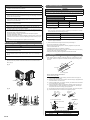
INSTALLATION MANUAL
English
AIR CONDITIONER
OUTDOOR UNIT
Tϋrkçe
Русский
Português
EλληvIkά
Italiano
Español
Français
Deutsch
For authorized personnel only.
PART NO. 9379069106-02
En-1
Contents
1. SAFETY PRECAUTIONS ……………………………………………………………… 1
• When installing and relocating the air conditioner, do not mix gases other than
the specified refrigerant (R410A) to enter the refrigerant cycle.
If air or other gas enters the refrigerant cycle, the pressure inside the cycle will
rise to an abnormally high value and cause breakage, injury, etc.
2. ABOUT THE PRODUCT
2.1. Precautions for using R410A refrigerant ………………………………………… 2
2.2. Special tools for R410A …………………………………………………………… 2
2.3. Accessories ………………………………………………………………………… 2
2.4. Optional parts ……………………………………………………………………… 2
2.5. Operating range …………………………………………………………………… 2
2.6. System configuration ……………………………………………………………… 3
• Do not remove the connection pipe while the compressor is in operation with
2-way or 3-way valve open.
This may cause abnormal pressure in the refrigeration cycle that leads to
breakage and even injury.
3. INSTALLATION WORK
3.1. Selecting an installation location ………………………………………………… 4
3.2. Drain installation …………………………………………………………………… 4
3.3. Installation dimensions …………………………………………………………… 4
3.4. Transportation of the unit ………………………………………………………… 5
3.5. Installation of the unit ……………………………………………………………… 5
• Connect the indoor unit and outdoor unit with the air conditioner piping and
cords available standards parts.
This installation manual describes the correct connections using the installation
set available from our standard parts.
4. SYSTEM CONFIGURATION
4.1. Piping limitation and Pipe size …………………………………………………… 6
5. PIPE INSTALLATION
5.1. Opening a knockout hole ………………………………………………………… 7
5.2. Separation tube connection ……………………………………………………… 7
5.3. Flare connection (pipe connection) ……………………………………………… 7
6. ELECTRICAL WIRING
6.1. The precautions of electrical wiring ……………………………………………… 8
6.2. Knockout hole ……………………………………………………………………… 9
6.3. Electrical requirement ……………………………………………………………… 9
6.4. Unit wiring …………………………………………………………………………… 9
6.5. Wiring method …………………………………………………………………… 10
6.6. Connecting of wiring …………………………………………………………… 10
7. PIPE INSTALLATION II
7.1. Sealing test ………………………………………………………………………
7.2. Vaccum process …………………………………………………………………
7.3. Additional charging ………………………………………………………………
7.4. Refrigerant recovery method ……………………………………………………
7.5. Installing insulation ………………………………………………………………
7.6. Filling with putty …………………………………………………………………
11
11
11
12
12
12
8. FIELD SETTING
8.1. Field setting switches …………………………………………………………… 12
8.2. Function settings ………………………………………………………………… 13
9. TEST OPERATION
9.1. Check run ………………………………………………………………………… 15
9.2. TEST RUN ……………………………………………………………………… 16
9.3. Confirming the operation of indoor unit………………………………………… 18
10. EXTERNAL INPUT & OUTPUT
10.1. Fitting cable (optional parts) …………………………………………………… 18
10.2. External input …………………………………………………………………… 18
10.3. External output …………………………………………………………………… 19
11. LED Display
11.1. Normal operation mode ………………………………………………………… 19
11.2. Error display mode ……………………………………………………………… 19
1. SAFETY PRECAUTIONS
• Be sure to read this Manual thoroughly before installation.
• The warnings and precautions indicated in this Manual contain important
information pertaining to your safety. Be sure to observe them.
• Hand this Manual, together with the Operating Manual, to the customer. Request
the customer to keep them on hand for future use, such as for relocating or
repairing the unit.
• After installation, explain correct operation to the customer, using the operating
manual.
WARNING
This mark indicates procedures which, if improperly
performed, might lead to the death or serious injury of the
user.
• Never touch electrical components immediately after the power supply has been
turned off. Electrical shock may occur. After turning off the power, always wait
10 minutes or more before touching electrical components.
• Request your dealer or a professional installer to install the indoor unit in
accordance with this Installation Manual. An improperly installed unit can cause
serious accidents such as water leakage, electric shock, or fire. If the indoor unit
is installed in disregard of the instructions in the Installation Manual, it will void
the manufacturer’s warranty.
• Do not turn ON the power until all work has been completed. Turning ON the
power before the work is completed can cause serious accidents such as
electric shock or fire.
• If refrigerant leaks while work is being carried out, ventilate the area. If the
refrigerant comes in contact with a flame, it produces a toxic gas.
• Installation work must be performed in accordance with national wiring
standards by authorized personnel only.
• During installation, make sure that the refrigerant pipe is attached firmly before
you run the compressor.
Do not operate the compressor under the condition of refrigerant piping not
attached properly with 2-way or 3-way valve open. This may cause abnormal
pressure in the refrigeration cycle that leads to breakage and even injury.
En-1
• For the air conditioner to operate satisfactorily, install it as outlined in this
installation manual.
• Also, do not use an extension cord.
• Do not purge the air with refrigerants but use a vacuum pump to vacuum the
installation.
• There is not extra refrigerant in the outdoor unit for air purging.
• Use a vacuum pump for R410A exclusively.
• Using the same vacuum pump for different refrigerants may damage the
vacuum pump or the unit.
• Use a clean gauge manifold and charging hose for R410A exclusively.
CAUTION
This mark indicates procedures which, if improperly
performed, might possibly result in personal harm to the
user, or damage to property.
• Read carefully all security information before use or install the air conditioner.
• Do not attempt to install the air conditioner or a part of the air conditioner by
yourself.
• This unit must be installed by qualified personnel with a capacity certificate for
handling refrigerant fluids. Refer to regulation and laws in use on installation
place.
• The installation must be carried out in compliance with regulations in force in the
place of installation and the installation instructions of the manufacturer.
• This unit is part of a set constituting an air conditioner. It must not be installed
alone or with non-authorized by the manufacturer.
• Always use a separate power supply line protected by a circuit breaker operating
on all wires with a distance between contact of 3mm for this unit.
• The unit must be correctly grounded and the supply line must be equipped with
a differential breaker in order to protect the persons.
• The units are not explosion proof and therefore should not be installed in
explosive atmosphere.
• Do not turn on the power until all installation work is complete.
• Never touch electrical components immediately after the power supply has been
turned off. Electric shock may occur. After turning off the power, always wait 5
minutes before touching electrical components.
• This unit contains no user-serviceable parts. Always consult authorized service
personnel to repairs.
• When moving, consult authorized service personnel for disconnection and
installation of the unit.
• Children should be monitored to ensure they do not play with the device.
• This product is not intended to be used by people (including children) with
physical, sensory or mental disability, or persons lacking experience or
knowledge unless they have been given by the through a person responsible for
their safety, supervision or instruction concerning the use of the device.
2. 4. Optional parts
2. ABOUT THE PRODUCT
CAUTION
2. 1. Precautions for using R410A refrigerant
The following parts are optional parts specific to R410A refrigerant.
Do not use parts other than those listed below.
WARNING
The basic installation work procedures are the same as conventional refrigerant
models.
However, pay careful attention to the following points:
1 Since the working pressure is 1.6 times higher than that of conventional
refrigerant (R22) models, some of the piping and installation and service tools
are special. (See the table below.)
Especially, when replacing a conventional refrigerant (R22) model with a new
refrigerant R410A model, always replace the conventional piping and flare nuts
with the R410A piping and flare nuts.
2 Models that use refrigerant R410A have a different charging port thread diameter
to prevent erroneous charging with conventional refrigerant (R22) and for safety.
Therefore, check beforehand. [The charging port thread diameter for R410A is
1/2 UNF 20 threads per inch.]
3 Be careful that foreign matter (oil, water, etc.) does not enter the piping than with
refrigerant models. Also, when storing the piping, securely seal the openings by
pinching, taping, etc.
Refer to the installation manual for the Branch box and the Separation tubes.
Parts name
Model name
Separation tube
UTP-SX248A
3 Branches
UTP-PY03A
2 Branches
UTP-PY02A
Branch box
External connect kit
(for External input/output)
UTY-XWZXZ3
External connect kit
(for Base heater)
UTY-XWZXZ4
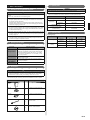
2. 5. Operating range
Operating range
4 When charging the refrigerant, take into account the slight change in the
composition of the gas and liquid phases. And always charge from the liquid
phase where refrigerant composition is stable.
Temperature
Indoor air intake
Outdoor air intake
Maximum
32 °C DB
46 °C DB
Minimum
18 °C DB
-5 °C DB
Cooling
2. 2. Special tools for R410A
Maximum
30 °C DB
24 °C DB
Minimum
16 °C DB
-15 °C DB
Heating
Tool name
Gauge manifold
Charge hose
Contents of change
Indoor humidity about 80% or less
Pressure is high and cannot be measured with a
conventional gauge. To prevent erroneous mixing of other
refrigerants, the diameter of each port has been changed.
It is recommended the gauge with seals –0.1 to 5.3 MPa
(-1 to 53 bar) for high pressure. –0.1 to 3.8 MPa (-1 to 38
bar) for low pressure.
To increase pressure resistance, the hose material and
base size were changed.
Vacuum pump
A conventional vacuum pump can be used by installing a
vacuum pump adapter.
Gas leakage
detector
Special gas leakage detector for HFC refrigerant R410A.
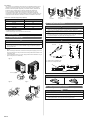
2. 3. Accessories
WARNING
• For installation purposes, be sure to use the parts supplied by the manufacturer
or other prescribed parts. The use of non-prescribed parts can cause serious
accidents such as the unit falling, water leakage, electric shock, or fire.
Do not throw away the connecting parts until the installation has been complete.
Name and shape
Q’ty
Installation
manual
Application
(This book)
1
Drain cap
For outdoor unit drain piping work
2
Drain pipe
For outdoor unit drain piping work
1
Binder
For binding power supply cable and
connection cable
3
One-touch bush
For power supply cable and
connection cable installation
2
En-2
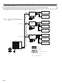
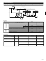
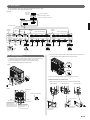
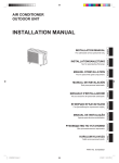
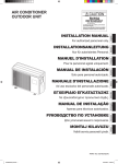
2. 6. System configuration
• 2 to 8 indoor units can be connected.
• The total capacity of the indoor units connected must be between 11.2 (kw) and 18.2 (kw). For details, refer to the DESIGN&TECHNICAL MANUAL.
• If the total capacity of the connected indoor units exceeds 18.2 (kw) or less than 11.2 (kw), an error will be displayed and the units will be not operate.
For the installation method of Branch box and indoor units, refer to the installation manuals that come with them.
Indoor unit
Branch box
(Secondary2)
Indoor unit
Breaker2
Primary unit
: Branch box that is connected to the Outdoor unit.
Secondary unit : Branch box that is connected to the Branch box
(Primary).
Breaker1
Power supply
Indoor unit
Separation tube
Branch box
(Secondary1)
Indoor unit
Breaker2
Breaker1
Power
supply
Indoor unit
Indoor unit
Separation tube
Branch box
(Primary)
Indoor unit
Breaker2
Outdoor unit
Breaker1
Power
supply
Indoor unit
Piping
Breaker2
Breaker1
Power supply
Transmission line
Power supply and Transmisson line
Power
supply
Breaker2 Circuit breaker (over current)
Breaker1 Earth leakage breaker
En-3
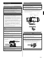
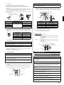
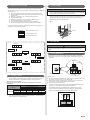
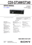
3. 2. Drain installation
3. INSTALLATION WORK
Please obtain the approval of the customer when selecting the location of installation
and installing the unit.
CAUTION
• Perform drain work in accordance with this Manual, and ensure that the drain
water is properly drained. If the drain work is not carried out correctly, water may
drip down from the unit, wetting the furniture.
3. 1. Selecting an installation location
WARNING
• Securely install the outdoor unit at a location that can withstand the weight of
the unit. Otherwise, the outdoor unit may fall and cause injury.
• Be sure to install the outdoor unit as prescribed, so that it can withstand
earthquakes and typhoons or other strong winds. Improper installation can
cause the unit to topple or fall, or other accidents.
• Do not install the outdoor unit near the edge of a balcony. Otherwise, children
may climb onto the outdoor unit and fall off of the balcony.
• When the outdoor temperature is 0 °C or less, do not use the accessory drain pipe
and drain cap. If the drain pipe and drain cap are used, the drain water in the pipe
may freeze in extremely cold weather. (Reverse cycle model only)
• As the drain water flows out of the outdoor unit during heating operation, install the
drain pipe and connect it to a commercial 16mm hose. (Reverse cycle model only)
• When installing the drain pipe, plug all the holes other than the drain pipe
mounting hole in the bottom of the outdoor unit with putty so there is no water
leakage. (Reverse cycle model only)
(Unit:mm)
Drain cap mounting hole ×2
CAUTION
227
305
Drain pipe mounting
hole ×1
341
• Do not install the outdoor unit in the following areas:
• Area with high salt content, such as at the seaside. It will deteriorate metal
parts, causing the parts to fail or the unit to leak water.
• Area filled with mineral oil or containing a large amount of splashed oil or
steam, such as a kitchen. It will deteriorate plastic parts, causing the parts to
fail or the unit to leak water.
• Area that generates substances that adversely affect the equipment, such as
sulfuric gas, chlorine gas, acid, or alkali. It will cause the copper pipes and
brazed joints to corrode, which can cause refrigerant leakage.
• Area containing equipment that generates electromagnetic interference. It will
cause the control system to malfunction, preventing the unit from operating
normally.
• Area that can cause combustible gas to leak, contains suspended carbon
fibers or flammable dust, or volatile inflammables such as paint thinner or
gasoline. If gas leaks and settles around the unit, it can cause a fire.
• Area that has heat sources, vapors, or the risk of the leakage of flammable
gas in the vicinity.
• Area where small animals may live. It may cause failure, smoke or fire if small
animals enter and touch internal electrical parts.
• Area where animals may urinate on the unit or ammonia may be generated.
50
438
622
Drain pipe mounting hole
• Please install the outdoor unit without slant.
Base
• Install the outdoor unit in a well-ventilated location away from rain or direct
sunlight.
• If the outdoor unit must be installed in an area within easy reach of the general
public, install as necessary a protective fence or the like to prevent their access.
• Install the outdoor unit in a location that would not inconvenience your
neighbors, as they could be affected by the airflow coming out from the outlet,
noise, or vibration. If it must be installed in proximity to your neighbors, be sure
to obtain their approval.
• If the outdoor unit is installed in a cold region that is affected by snow
accumulation, snow fall, or freezing, take appropriate measures to protect it
from those elements. To ensure a stable operation, install inlet and outlet ducts.
• Install the outdoor unit in a location that is away from exhaust or the vent ports
that discharge vapor, soot, dust, or debris.
• Install the indoor unit, outdoor unit, power supply cable, connection cable, and
remote control cable at least 1 m away from a television or radio receivers. The
purpose of this is to prevent TV reception interference or radio noise. (Even if
they are installed more than 1 m apart, you could still receive noise under some
signal conditions.)
1 m or more
Branch switch and
circuit breaker
1m or more
Branch switch and
circuit breaker
• If children under 10 years old may approach the unit, take preventive measures
so that they cannot reach the unit.
• Keep the length of the piping of the indoor and outdoor units within the allowable
range.
• For maintenance purposes, do not bury the piping.
Drain pipe
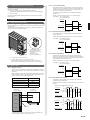
3. 3. Installation dimensions
CAUTION
• The installation space shown in the following examples is based on an ambient
temperature under cooling operation of 35 °C (DB) at the air intake of the
outdoor unit. Provide more space around the air intake than shown in the
examples if the ambient temperature exceeds 35 °C (DB) or if the thermal load
of all of the outdoor units exceeds the capacity.
• Consider the transportation route, installation space, maintenance space, and
access, and install the unit in a location with sufficient space for the refrigerant
piping.
• Observe the installation space specifications that are shown in the figures.
Provide the same space for the air intake at the rear of the outdoor unit.
If the installation is not performed according to the specifications, it could cause
a short circuit and result in a lack of operating performance. As a result, the
outdoor unit might easily be stopped by high-pressure protection.
Air intake
Rear view
• Installation methods not shown in the following examples are not recommended.
Performance may drop significantly.
En-4
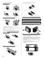
3. 3. 1. Single outdoor unit installation
3. 3. 3. Outdoor units installation in multi row (Unit: mm)
When the upward area is open (Unit: mm)
(1) Single parallel unit arrangement
(1) Obstacles at rear only
(2) Obstacles at rear and sides only
150
2000 or more
600
1000
150
200
300
(2) Multiple parallel unit arrangement
200
(3) Obstacles at front only
(4) Obstacles at front and rear only
500
3000 or more
1000 or more
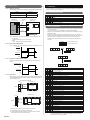
When an obstruction is present also in the upward area (Unit : mm)
(1) Obstacles at rear and above only
600
1500
150
1000 or more
3. 4. Transportation of the unit
(2) Obstacles at rear, sides, and above
only
WARNING
• Do not touch the fins. Otherwise, personal injury could result.
1500
1000
CAUTION
• When carrying the unit, hold the handles on the right and left sides and be careful.
If the outdoor unit is carried from the bottom, hands or fingers may be pinched.
300
Max. 500
500
250
Max. 500
250
• Be sure to hold the handles on the sides of the unit. Otherwise, holding the suction
grille on the sides of the unit may cause deformation.
3. 3. 2. Multiple outdoor unit installation
• Provide at least 25mm of space between the outdoor units if multiple units are
installed.
• When routing the piping from the side of an outdoor unit, provide space for the
piping.
Suction
grille
Handle
• No more than 3 units must be installed side by side.
When 3 units or more are arranged in a line, provide the space as shown in the
following example when an obstruction is present also in the upward area.
Handle
Handle
When the upward area is open (Unit: mm)
(2) Obstacles at front only
(1) Obstacles at rear only
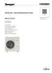
3. 5. Installation of the unit
1500 or more
300
(3) Obstacles at front and rear only
• Install 4 anchor bolts at the locations indicated with arrows in the figure.
• To reduce vibration, do not install the unit directly on the ground. Install it on a
secure base (such as concrete blocks).
• The foundation shall support the legs of the unit and have a width of 50mm or more.
• Depending on the installation conditions, the outdoor unit may spread its vibration
during operation, which may cause noise and vibration. Therefore, attach damping
materials (such as damping pads) to the outdoor unit during installation.
• Install the foundation, making sure that there is enough space for installing the
connection pipes.
• Secure the unit to a solid block using foundation bolts.(Use 4 sets of commercially
available M10 bolts, nuts, and washers.)
• The bolts should protrude 20mm. (Refer to the figure.)
• If overturning prevention is required, purchase the necessary commercially
available items.
(Unit : mm)
500
166
1500 or more
650
154
AIR
50
When an obstruction is present also in the upward area (Unit: mm)
410
16
• Obstacles at rear and above only
50
1500
20
Bolt
1500
500
Max. 300
En-5
Nut
Base
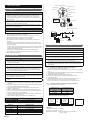
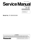
4. SYSTEM CONFIGURATION
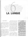
4. 1. Piping limitation and Pipe size
Outdoor
Unit
Separation Tube
a
b
c
H2
e
d
(Primary)
H1
H3
Indoor
Unit1
j
k
l
Indoor
Unit4
g
Indoor
Unit2
(Secondary2)
Branch Box
i
Branch Box
f
(Secondary1)
Branch Box
h
Indoor
Unit5
H4
Indoor
Unit6
m
Indoor
Unit7
Indoor
Unit8
Indoor
Unit3
Pipe limitation
Allowable
height
difference
Allowable pipe length
(actual pipe length)
Limitation
m
Diagram
Maximum total equivalent pipe length
115 or less
Total
Between outdoor unit and the farthest indoor unit
70 or less
a+b+c+m
Between outdoor unit and branch boxes
Between branch box and indoor unit
55 or less
a+b+c+d+e
Total
60 or less
f+g+h+i+j+k+l+m
Each unit
Between 3-15
f, g, h, i, j, k, l, m
Between outdoor unit and the first separation tube
5 or more
a
Between outdoor unit and branch box (when there is no separation tube)
5 or more
a+d
Between outdoor unit and indoor unit
30 or less
H1
Between outdoor unit and branch box
30 or less
H2
Between branch box and branch box
15 or less
H3
Between indoor unit and indoor unit
15 or less
H4
Pipe size selection
Diagram
Condition
(Model code of indoor unit)
Gas pipe
(mm (in.))
Liquid pipe
(mm (in.))
Between outdoor unit and first separation tube
a
―
Φ15.88 (5/8)
Φ9.52 (3/8)
Between first separation tube and second
separation tube
b
―
Φ15.88 (5/8)
Φ9.52 (3/8)
Between separation tube and branch box
c, d, e
―
Φ15.88 (5/8)
Φ9.52 (3/8)
7, 9, 12
Φ9.52 (3/8)
Φ6.35 (1/4)
14, 18
Φ12.70 (1/2)
Φ6.35 (1/4)
24
Φ15.88 (5/8)
Φ6.35 (1/4)
f, g, h, i,
Between branch box and indoor unit
j, k, l, m
En-6
Pipe material
It is necessary to use seamless copper pipes and it is desirable that the amount of
residual oil is less than 40mg/10m. Do not use copper pipes having a collapsed,
deformed or discolored portion (especially on the interior surface). Otherwise, the
expansion valve or capillary tube may become blocked with contaminants.
As an air conditioner using R410A incurs pressure higher than when using
conventional refrigerant (R22), it is necessary to choose adequate materials.
Thicknesses of copper pipes used with R410A are as shown in the table. Never use
copper pipes thinner than that in the table even when it is available on the market.
Thicknesses of Annealed Copper Pipes (R410A)
Pipe outside diameter (mm (in.))
Front
connection
Lateral
connection
Bottom
connection
Rear
connection
Thickness (mm)
6.35 (1/4)
0.80
9.52 (3/8)
0.80
12.70 (1/2)
0.80
15.88 (5/8)
1.00
19.05 (3/4)
1.20
5. 2. Separation tube connection
CAUTION
• Use genuine separation tubes for the refrigerant piping branches. Separation
tubes may be used for piping between the outdoor unit and branch box.
* JIS H3300 C1220T-O or equivalent
* Please select the pipe size in accordance with local rules.
• Select number of separation tubes and purchase it before starting the installation
work.
• Any vertical piping shall be in the part of the main piping. If a main pipe is bent, keep
the straight part more than 10 times the diameter of the connected pipe. A variance in
the amount of refrigerant may be caused if the straight part is short.
5. PIPE INSTALLATION
5. 1. Opening a knockout hole
• For details, refer to the Installation Manual of separation tubes.
CAUTION
CAUTION
• Be careful not to deform or scratch the panel while opening the knockout holes.
Separation tube
A
• To protect the piping insulation after opening a knockout hole, remove any burrs
from the edge of the hole. It is recommended to apply rust prevention paint to
the edge of the hole.
B
B
Horizontal
Vertical
• Pipes can be connected from 4 directions, front, lateral side, rear side and bottom.
(Fig. A)
• When connecting at the bottom, remove the service panel and piping cover on the
front of the outdoor unit, and open the knockout hole provided at the bottom corner
of the piping outlet.
or
A
• It can be installed as shown on “Fig. B” cutting out the 2 slits as indicated on “Fig. C”.
(When cutting slits, use a steel saw.)
Horizontal
line
±15°
OK
Fig. A
B
A
A : Outdoor unit or Separation tube
B : Branch box or Separation tube
NO GOOD
Service panel
Name and shape
Liquid pipe
Fig. B
Gas pipe
Fig. C
5. 3. Flare connection (pipe connection)
CAUTION
• Do not use mineral oil on a flared part. Prevent mineral oil from getting into the
system as this would reduce the lifetime of the units.
• While welding the pipes, be sure to blow dry nitrogen gas through them.
Slit
Slit
En-7
Bottom
connection
• The maximum lengths of this product are shown in the table. If the units are
further apart than this, correct operation cannot be guaranteed.
5. 3. 1. Flaring
CAUTION
• Use special pipe cutter and flare tool exclusive for R410A.
• Hold the torque wrench at its grip, keeping it in a right angle with the pipe, in order
to tighten the flare nut correctly.
(1) Cut the connection pipe to the necessary length with a pipe cutter.
(2) Hold the pipe downward so that the cuttings will not enter the pipe and remove
any burrs.
(3) Insert the flare nut (always use the flare nut attached to the indoor and outdoor
units respectively) onto the pipe and perform the flare processing with a flare tool.
Leakage of refrigerant may result if other flare nuts are used.
• Outer panel may be distorted if fastened only with a wrench. Be sure to fix the
elementary part with a holding wrench (spanner) and fasten with a torque wrench
(refer to below diagram). Do not apply force to the blank cap of the valve or hang a
wrench, etc., on the cap. If blank cap is broken, it may cause leakage of refrigerant.
Blank cap
(4) Protect the pipes by pinching them or with tape to prevent dust, dirt, or water from
entering the pipes.
Flare nut
Torque wrench
Check if [L] is flared uniformly
and is not cracked or scratched.
B
90°
Die
A
Holding
wrench
Pipe
L
Torque wrench
Pipe outside
diameter [mm (in.)]
Dimension A (mm)
Flare tool for R410A,
clutch type
6.35 (1/4)
9.52 (3/8)
12.70 (1/2)
15.88 (5/8)
0 to 0.5
Dimension B
[mm]
0
- 0.4
9.1
13.2
16.6
19.7
• When using conventional flare tools to flare R410A pipes, the dimension A should
be approximately 0.5mm more than indicated in the table (for flaring with R410A
flare tools) to achieve the specified flaring. Use a thickness gauge to measure the
dimension A.
Width across flats
Flare nut
[mm (in.)]
6.35 (1/4) dia.
9.52 (3/8) dia.
12.70 (1/2) dia.
15.88 (5/8) dia.
19.05 (3/4) dia.
Pipe outside
diameter
[mm (in.)]
Width across flats
of Flare nut
[mm]
6.35 (1/4)
9.52 (3/8)
12.70 (1/2)
15.88 (5/8)
17
22
26
29
5. 3. 2. Bending pipes
CAUTION
• To prevent breaking of the pipe, avoid sharp bends. Bend the pipe with a radius of
curvature of 100mm or more.
Tightening torque
[N·m (lgf·cm)]
16 to 18 (160 to 180)
32 to 42 (320 to 420)
49 to 61 (490 to 610)
63 to 75 (630 to 750)
90 to 110 (900 to 1100)
5. 3. 4. Handling precautions for the valves
• Mounted part of Blank cap is sealed for protection.
• Fasten blank cap tightly after opening valves.
Operating the valves
• Use a hexagon wrench (size 4mm).
• Opening
(1) Insert the hexagon wrench into the valve shaft, and turn it
counterclockwise.
(2) Stop turning when the valve shaft can no longer be turned.
(Open position)
• Closing
(1) Insert the hexagon wrench into the valve shaft, and turn it
clockwise.
(2) Stop turning when the valve shaft can no longer be turned.
(Closed position)
Opening direction
Hexagon wrench
Opening direction
Seal (blank cap
installation portion)
• If the pipe is bent repeatedly at the same place, it will break.
• If pipes are shaped by hand, be careful not to collapse them.
• Do not bend the pipes at an angle of more than 90°.
• When pipes are repeatedly bent or stretched, the material will harden, making it
difficult to bend or stretch them any more.
Liquid pipe
Gas pipe
• Do not bend or stretch the pipes more than 3 times.
5. 3. 3. Pipe connection
6. ELECTRICAL WIRING
CAUTION
• Be sure to install the pipe against the port on the indoor unit and the outdoor unit
correctly. If the centering is improper, the flare nut cannot be tightened smoothly.
If the flare nut is forced to turn, the threads will be damaged.
• Do not remove the flare nut from the outdoor unit pipe until immediately before
connecting the connection pipe.
• After installing the piping, make sure that the connection pipes do not touch the
compressor or outer panel. If the pipes touch the compressor or outer panel, they
will vibrate and produce noise.
(1) Detach the caps and plugs from the pipes.
(2) Center the pipe against the port on the outdoor unit, and then turn the flare nut
by hand.
(3) Tighten the flare nut of the connection pipe at the outdoor unit valve connector.
(4) After tightening the flare nut by hand, use a torque wrench to fully tighten it.
3-way valve (Liquid)
Flare nut
Connection pipe
(Liquid)
3-way valve (Gas)
Flare nut
Connection pipe
(Gas)
6. 1. The precautions of electrical wiring
WARNING
• Wiring connections must be performed by a qualified person in accordance with
specifications.
The rated supply of this product is 50Hz, 230V. Use a voltage within the range of
198-264V.
• Before connecting the wires, make sure the power supply is OFF.
• Be sure to install a breaker of the specified capacity. When selecting breaker,
please comply with the laws and the regulations of each country. One breaker
must be installed on the power supply of the outdoor unit. Wrong selection and
setup of the breaker will cause electric shock or fire.
• Be sure to install an earth leakage breaker. Otherwise, it will cause electric shock
or fire.
• Do not connect AC power supply to the transmission line terminal board.
Improper wiring can damage the entire system.
• Connect the connector cord securely to the terminal.
Faulty installation can cause a fire.
• Make sure to secure the insulation portion of the connector cable with the cord
clamp. A damaged insulation can cause a short circuit.
• Never install a power factor improvement condenser. Instead of improving the
power factor, the condenser may overheat.
• Before servicing the unit, turn the power supply switch OFF. Then, do not touch
electric parts for 10 minutes due to the risk of electric shock.
• Make sure to perform grounding work. Improper grounding work can cause
electric shocks.
En-8
6. 3. Electrical requirement
CAUTION
• The primary power supply capacity is for the air conditioner itself, and does not
include the concurrent use of other devices.
CAUTION
• Do not use crossover power supply wiring for the outdoor unit.
Be sure to install a breaker of the specified capacity.
• If the electrical power is inadequate, contact your electric power company.
Regulation of cables and breaker differs from each locality, refer in accordance with
local rules.
• Install a breaker in a location that is not exposed to high temperatures.
If the temperature surrounding the breaker is too high, the amperage at which the
breaker cuts out may decrease.
• Use a breaker that is capable of handling high frequencies. Because the outdoor
unit is inverter controlled, a high-frequency breaker is necessary to prevent a
malfunction of the breaker itself.
• When the electrical switchboard is installed outdoors, place it under lock and key
so that it is not easily accessible.
• Do not fasten the power supply cable and connection cable together.
• Always keep to the maximum length of the connection cable. Exceeding the
maximum length may lead to erroneous operation.
• The static electricity that is charged to the human body can damage the control
PC Board when handling the control PC Board for address setting, etc.
Please keep caution to the following points.
Provide the grounding of Indoor unit, Outdoor unit and Option equipment.
Cut off the power supply (breaker).
Touch the metal section (such as the unpainted control box section) of the indoor
or outdoor unit for more than 10 seconds. Discharge the static electricity in your
body.
Never touch the component terminal or pattern on the PC Board.
6. 2. Knockout hole
CAUTION
• Be careful not to deform or scratch the panel while opening the knockout holes.
• When cables are routed from the unit, a protection sleeve for the conduits can
be inserted at the knockout hole.
• When cables through the opened knockout hole, install the one-touch bush.
For the installation method of the one-touch bush, refer to "6.6. Connecting of
wiring".
• It is recommended to apply anti-rust paint to the edge of the knockout hole.
• Knockout holes are provided for wiring. (Fig. A)
Voltage rating
1Φ 230V (50Hz)
Operating range
198-264V
Cable size (mm2) *1)
Cable
Remarks
Power supply cable
6.0
2 cable + Ground, 1 Ø 230V
Connection cable
2.5
3 cable + Ground, 1 Ø 230V
1) Selected sample: Select the correct cable type and size according to the country
or region’s regulations.
Max. wire length: Set a length so that the voltage drop is less than 2%. Increase
the wire diameter when the wire length is long.
Breaker
Specification
Circuit breaker (over current)
*2)
Current : 32 (A)
Earth leakage breaker
Leakage current : 30mA 0.1sec or less
*3)
2) Select the appropriate breaker of the described specification according to the
national or regional standards.
3) Select the breaker that enough load current can pass through it.
• Use conformed cable with Type245 IEC57.
• Before starting work check that power is not being supplied to all poles of the
indoor unit and outdoor unit.
• Install all electrical works in accordance to standard.
• Install the disconnect device with a contact gap of at least 3mm in all poles nearby
the units. (Both indoor unit and outdoor unit)
• Wiring size must comply with the applicable local and national code.
6. 4. Unit wiring
• When stripping off the coating of a lead wire, always use a special tool such as a
wire stripper. If there is no special tool available, carefully strip the coating with a
knife etc.
• Knockout holes are provided 2 each in the same size in front, lateral and rear
sides. (Fig. B)
mm
30
Fig. A
Earth cable
mm
35
Power supply cable
How to connect wiring to the terminal
Caution when wiring cable
(1) Use crimp-type terminals with insulating sleeves as shown in the figure to
connect to the terminal block.
(2) Securely clamp the crimp-type terminals to the wires using an appropriate tool
so that the wires do not come loose.
(3) Use the specified wires, connect them securely, and fasten them so that there
is no stress placed on the terminals.
(4) Use an appropriate screwdriver to tighten the terminal screws. Do not use a
screwdriver that is too small, otherwise, the screw heads may be damaged
and prevent the screws from being properly tightened.
(5) Do not tighten the terminal screws too much, otherwise, the screws may break.
(6) See the table below for the terminal screw tightening torques.
Service panel
Fig. B
Crimp-type
terminal
Strip : 10mm
Sleeve
Screw with
special washer
Screw with special washer
Wire
Crimp-type terminal
Crimp-type
terminal
Front connection
Lateral connection
Rear connection
Terminal blocks
Wire
Tightening torque [N·m (kgf·cm)]
M4 screw
M5 screw
En-9
1.2 to 1.8 (12 to 18)
2.0 to 3.0 (20 to 30)
6. 5. Wiring method
The wiring example for Outdoor unit, indoor units and Branch box is shown in figure.
For other connections, refer to Design&Technical Manual.
[Example]
Single-phase
230V 50Hz
Max.26.5A
Power supply cable
Outdoor unit
BRANCH BOX
Breaker1
Breaker1: Earth leakage breaker
Breaker2
Breaker2: Circuit breaker (over current)
POWER
1 2 3
Connection cable
(Optional
terminal)
1 2 3
Branch
box
1 2 3
(Optional
terminal)
1 2 3
1 2 3
CENTRAL BRANCH BOX2 BRANCH BOX1 OUTDOOR UNIT
or BRANCH BOX
(OUT)
(OUT)
REMOTE
CONTROLLER
(IN)
INDOOR UNIT A INDOOR UNIT B INDOOR UNIT C POWER
1 2 3
1 2 3
1 2 3
Indoor
unit
Indoor
unit
Indoor
unit
1 2 3
1 2 3
1 2 3
1 2 3
CENTRAL BRANCH BOX2 BRANCH BOX1 OUTDOOR UNIT
REMOTE
(OUT)
(OUT)
or BRANCH BOX
CONTROLLER
(IN)
INDOOR UNIT A INDOOR UNIT B INDOOR UNIT C POWER
1 2 3
1 2 3
1 2 3
1 2 3
1 2 3
CENTRAL BRANCH BOX2 BRANCH BOX1 OUTDOOR UNIT
REMOTE
(OUT)
(OUT)
or BRANCH BOX
CONTROLLER
(IN)
INDOOR UNIT A INDOOR UNIT B INDOOR UNIT C POWER
1 2 3
1 2 3
1 2 3
1 2 3
Breaker2
Breaker2
Breaker2
Breaker1
Breaker1
Breaker1
1 2 3
BRANCH BOX
Branch box (Secondary2)
Branch box (Secondary1)
(Primary)
1 2 3
(Optional
terminal)
Indoor
unit
Indoor
unit
Indoor
unit
Single-phase
230V 50Hz
Indoor
unit
Single-phase
230V 50Hz
Indoor
unit
Single-phase
230V 50Hz
(3) Secure the cables using the binders under the terminal blocks, and then secure
the cables using the binders attached to the base of the valves.
6. 6. Connecting of wiring
(1) Remove the service covers and insulation sheet. And connect the wires to the
terminal in accordance with the terminal nameplate. (Fig. A, Fig. B)
(2) After connecting the wires, use binders to secure the wires. (Fig. B)
• Connect the wires without applying excessive tension.
Binder
(Accessory)
Fig. A
Binder
Terminal block
(4) Be sure to install the insulation sheet after the wiring is complete.
Installation method of One-touch bush
Please fix the One-touch bush (accessory) as shown in the figure below.
Front connection
Lateral connection
Rear connection
Service cover
Fig. B
Terminal block
Please remove the excess.
Binder
(Accessory)
Firmly secure the
binders so that the
wire terminals will not
receive external stress.
(Pipe cover rear)
Binder
(Accessory)
Use the specified wire
type and connect the
wires securely.
Binder
(Pipe cover front)
One-touch bush
(Accessories)
One-touch bush
(Accessories)
En-10
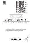
Service hose with valve core
7. PIPE INSTALLATION II
Charging port cap
Charging port
7. 1. Sealing test
Blank cap
3-way valve
WARNING
Connecting pipe
• Before operating the compressor, install the pipes and securely connect them.
Otherwise, if the pipes are not installed and if the valves are open when the
compressor operates, air could enter the refrigeration cycle. If this happens,
the pressure in the refrigeration cycle will become abnormally high and cause
damage or injury.
Gauge manifold
Hexagon wrench
Use a 4 mm
(5/32") hexagon
wrench
• After the installation, make sure there is no refrigerant leakage. If the refrigerant
leaks into the room and becomes exposed to a source of fire such as a fan
heater, stove, or burner, it produces a toxic gas.
Vacuum pump
• Do not subject the pipes to strong shocks during the sealing test. It can rupture
the pipes and cause serious injury.
Service hose
Pressure regulating valve
CAUTION
• For maintenance purposes, do not bury the piping of the outdoor unit.
Outdoor unit
Pressure gauge
• After connecting the pipes, perform a sealing test.
Nitrogen
• Make sure that the 3-way valves are closed before performing a sealing test.
• Pressurize nitrogen gas to 4.15 MPa to perform the sealing test.
• Add nitrogen gas to both the liquid pipes and the gas pipes.
Branch box
• Check all flare connections and welds. Then, check that the pressure has not
decreased.
• Compare the pressures after pressurizing and letting it stand for 24 hours, and
check that the pressure has not decreased. If the pressure has dropped, the pipe
joints may be leaking.
* When the outdoor air temperature changes 5 °C, the pressure changes 0.05 MPa
(0.5 bar). When outdoor air temperature raises/drops by 5 °C, the pressure will
raise/fall by 0.05 MPa accordingly.
• If a leak is found, immediately repair it and perform the sealing test again.
• After completing the sealing test, release the nitrogen gas from both valves.
Indoor unit
Vacuum pump
7. 3. Additional charging
CAUTION
• Do not turn on the power unless all operations are complete.
• Do not charge the system with a refrigerant other than R410A.
• Release the nitrogen gas slowly.
• Do not reuse recovered refrigerant.
7. 2. Vaccum process
• Use an electronic scale to measure the charging amount of refrigerant.
Adding more refrigerant than the specified amount will cause a malfunction.
CAUTION
• Perform a refrigerant leakage test (air tightness test) to check for leaks using
nitrogen gas while all valves in the outdoor unit are closed. (Use the pressure
indicated on the nameplate.)
• Be sure to evacuate the refrigerant system using a vacuum pump.
• The refrigerant pressure may sometimes not rise when a closed valve is opened
after the system is evacuated using a vacuum pump. This is caused by the
closure of the refrigerant system of the outdoor unit by the electronic expansion
valve. This will not affect the operation of the unit.
• If the system is not evacuated sufficiently, its performance will drop.
• Use a clean gauge manifold and charging hose that were designed specifically
for use with R410A. Using the same vacuum equipment for different refrigerants
may damage the vacuum pump or the unit.
• Do not purge the air with refrigerants, but use a vacuum pump to evacuate the
system.
1) Check that the valves are closed by removing the blank caps from the gas and
liquid pipes.
2) Remove the charging port cap, and connect the gauge manifold and the vacuum
pump to the charging valve with the service hoses.
3) Vacuum the indoor unit and the connecting pipes until the pressure gauge
indicates –0.1 MPa (-1bar).
4) When –0.1 MPa (-1bar) is reached, make sure it hold vacuum for 60 minutes.
5) Disconnect the service hoses and fit the charging port cap to the charging valve
to the specified torque. (Refer to below table)
6) Remove the blank caps, and fully open the 3-way valves with a hexagon wrench
[Torque: 6 to 7 N·m (60 to 70 kgf·cm)].
7) Tighten the blank caps of the 3-way valve to the specified torque.
• Charge refrigerant using the liquid pipe.
Adding refrigerant through the gas pipe will cause a malfunction.
• Add refrigerant by charging the system with the refrigerant in the liquid state. If
the refrigerant cylinder is equipped with a siphon, it is not necessary to place the
cylinder upright.
7. 3. 1. Procedure for charging the system with refrigerant
1) Remove the charging cap from the liquid pipe.
2) Attach a charging hose to the refrigerant cylinder, and connect it to the charging
port.
3) Add refrigerant by calculating the additional refrigerant volume in accordance with
the calculation formula indicated below.
4) Remove the charging hose and install the charging cap.
5) Remove the blank caps (gas pipe, liquid pipe), and open the valves.
6) Close the blank caps.
7) After adding refrigerant, indicate the added charging volume on the unit.
* Tighten the blank caps and charging caps to the torque values specified.
To open and close the valves, use an M4 hexagon wrench for liquid and gas pipes.
7. 3. 2. Calculating the amount of refrigerant charge to be added
• Round up the value to 2 decimal places.
10 to 12 (100 to 120)
6 to 7 (60 to 70)
Blank cap
[mm (in.)]
6.35 (1/4)
9.52 (3/8)
12.70 (1/2)
15.88 (5/8)
19.05 (3/4)
Tightening torque
[N·m (kgf·cm)]
20 to 25 (200 to 250)
20 to 25 (200 to 250)
25 to 30 (250 to 300)
30 to 35 (300 to 350)
35 to 40 (350 to 400)
Additional amount for
pipe length
(kg/m)
0.021
Φ9.52 (3/8)
0.058
Calculation of additional amount for pipe length
Tightening torque [N·m (kgf·cm)]
Charging port cap
3-way valve
Diameter of liquid
pipe
(mm (in.))
Φ6.35 (1/4)
L=
Total length
of Φ6.35mm
(Φ1/4in.)
liquid pipe
× 0.021
kg/m
m
En-11
+
Total length
of Φ9.52mm
(Φ3/8in.)
liquid pipe
× 0.058
kg/m
Total
=
m
kg
kg
<Example>
If liquid pipe piping length is the following
Φ9.52 (3/8) : 20m, Φ6.35 (1/4) : 15m
Additional charge volume L=20(m)×0.058(kg/m)+15(m)×0.021(kg/m)
=1.475kg≒1.48kg
kg
7. 6. Filling with putty
7. 4. Refrigerant recovery method
㶎㩷Please perform the refrigerant recovery according to the local law and rules.
The refrigerant recovery of this type of equipment must be performed by a refrigerant
recovery machine.
①
②
③
④
⑤
⑥
⑦
⑧
Turn on both the power supplies of the outdoor unit and the branch boxes.
Press the “MODE/EXIT” button of the outdoor unit when all units are in stop
operation state.
Match the 7 seg. display to “F3” by pushing the SELECT button.
Press the “ENTER” button.
Match the 7 seg. display to “21” by pushing the “SELECT” button.
Press the “ENTER” button for about 5 seconds.
Turn off the power supplies of all units when “P.oFF” is displayed.
Perform the refrigerant recovery with the refrigerant recovery machine.
WARNING
• Fill the piping holes and wiring holes with putty (supplied locally) to avoid any gap
(Fig A). If small animals such as insects enter the external unit, a short circuit may
be caused near electrical components in the service panel.
• If the outdoor unit is installed at a level that is higher than the indoor unit, the water
that has condensed in the 3-way valve of the outdoor unit could travel to the indoor
unit. Therefore, use putty in the space between the pipe and the insulation to
prevent the entry of water to the indoor units.
Fig. A
It cannot be operated in the “P.oFF” state. Please turn on the power supplies of all
units again in case of performing operation.
MODE/EXIT
Insulation
: Press the “MODE/EXIT” button.
SELECT
: Press the “SELECT” button.
ENTER
: Press the “ENTER” button.
Putty
8. FIELD SETTING
7 seg.display
CAUTION
Discharge the static electricity from your body before setting up the DIP switches.
Never touch the terminals or the patterns on the parts that are mounted on the
board.
MODE/EXIT
SELECT
×2
8. 1. Field setting switches
(Blinking)
(Blinking)
ENTER
Set the functions of an outdoor unit with the push buttons (SW931, SW932 and
SW933) while observing the 7 seg. display (LED961 and LED962) on the printed
circuit board.
LED lamp
(Blinking)
SELECT
×3
(Blinking)
7 seg.display
ENTER
LED981
POWER
MODE
LED961
LED982
ERROR
LED962
MODE / EXIT
SELECT
ENTER
CHECK
SW931
SW932
SW933
SW934
Outdoor unit printed circuit board
Push button
7. 5. Installing insulation
• Use an insulation on the refrigerant pipes to prevent condensation and dripping.
• Determine the thickness of the insulation material by referring to Table A.
Table A, Selection of insulation
(for using an insulation material with equal heat transmission rate or below
0.040 W/(m·k))
Relative humidity
[mm (in.)]
Pipe diameter
6.35 (1/4)
9.52 (3/8)
12.70 (1/2)
15.88 (5/8)
Insulation material
Minimum thickness [mm]
70% or more 75% or more 80% or more 85% or more
8
10
13
17
9
11
14
18
10
12
15
19
10
12
16
20
PREPARATION
1 Be sure to check that the operation of the outdoor unit has stopped (be sure to stop
the operation if it is still running), and turn off the power.
2 Remove the front panel of the outdoor unit, and remove the lid of the electrical
component box in order to expose the printed circuit board.
3 Turn on the power of the outdoor unit.
As shown in the above figure, make sure that the POWER/MODE indicator lamp
(LED981) is on and the ERROR indicator lamp (LED982) is off.
• If the ERROR indicator lamp (LED982) flashes, it indicates that an error has
occurred. Check wiring and power supply. After making sure that the ERROR
indicator lamp (LED982) has turned off, proceed to the next step.
(On)
• If the ambient temperature and relative humidity exceed 32 °C, increase the level
of heat insulation for the refrigerant pipes.
(Off)
LED981
POWER
MODE
LED961
(Off)
LED982
ERROR
LED962
When the system is normal
(Off)
En-12
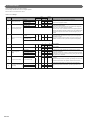
8. 2. Function settings
Various functions can be set. Set when necessary.
Perform settings after all indoor units have stopped operation.
Refer to Table A for the items that can be set.
Table. A: List of Settings
No
Setting Item
7 seg
First 2 digits Last 2 digits
Standard
11
Cooling capacity shift
0
0
0
1
High power mode2
0
2
Batch stop
0
0
0
1
0
0
0
1
High power mode1
Emergency stop
20
1
2
1
0
2
• Please set this item when cooling ability is inadequate.
• If cooling ability is inadequate due to the setting of “High power mode1”,
please set it to “High power mode2”.
z
This mode selects the pattern of the stop function to be operated by the
external input terminal (CN934).
• Batch stop: The stop of all indoor units connected to same refrigerant
system due to input signal coming from CN934.
• Emergency stop: The air conditioner returns to the original operation if
input from the CN934 is stopped. Furthermore, the air conditioner does
not accept the operation of the indoor unit when emergency stop is
actuated.
Priority given to external
Operation mode selecting
input of outdoor unit
method
28
Forbidden
Forbidden
2
8
29
Forbidden
Forbidden
2
9
30
Energy saving level
setting
0
0
0
1
0
0
0
1
Level 1 (stop)
0
0
Level 2 (Limited at 50%)
0
1
Level 3 (Limited at 75%)
3
0
0
2
Level 4 (Limited at 100%)
0
3
Off (Normal)
0
0
0
1
0
0
0
1
0
2
41
Low noise mode setting
42
Level 1 (-3dB)
Low noise mode operation
Level 2 (-6dB)
level setting
Level 3 (-9dB)
On (Low noise mode)
z
1
21
4
1
4
2
Content
z
Switching between batch
stop or emergency stop
Priority given to the frst
command
En-13
Factory
default
Select the priority setting of the operation mode.
• Priority given to the first command: Priority is given to the operation
mode which is set first.
• Priority given to external input of outdoor unit: Priority is given to the
operation mode which is set by the external input terminal (CN932).
z
Setting forbidden
z
Setting forbidden
z
The capacity limit can be selected when operating with the “Energy
Saving Peak Cut function.”
The operation selection can be done by external input terminal (CN933).
The lower the level, the more the effect of energy saving, but the cooling/
heating performance decreases.
z
When “Low noise mode ON” is selected, the operating noise will be
suppressed.
Without external input terminal: It operates by selecting Low noise mode
ON.
With external input terminal: The operation selection can be done by
external input terminal (CN931) by selecting Low noise mode OFF.
z
The noise level when operating in the low noise mode can be set.
Cooling/heating performance decreases by lowering operation noise
level.
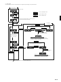
(1) Setting method
Use the MODE/EXIT, SELECT, and ENTER buttons to configure settings according to the procedures below.
1: Function Setting
First 2 digits Last 2 digits
7 seg. display
MODE/EXIT
MODE/EXIT
(Blinking)
: Press the “MODE/EXIT” button.
SELECT
: Press the “SELECT” button.
ENTER
: Press the “ENTER” button.
SELECT
(When [F3] to [F9] are displayed, continue to press the
SELECT button until [F2] is displayed.)
(Blinking)
ENTER
3: Setting the
last 2 digits
2: Setting the
first 2 digits
SELECT
(Continue to press the SELECT button until the
desired number appears at the last 2 digits.)
SELECT
SELECT
ENTER
(Blinking)
(Blinking)
(Blinking)
(Blinking)
ENTER
SELECT
(Press the ENTER button
for more than 3 seconds.)
Every press of the “SELECT”
button will change the setting
number for the first 2 digits.
Setting is complete when the lamp lights up
Press “ENTER” button to return to “2.Setting the first 2 digits”
(If there is no operation for 5 seconds after the setting, the display
will return to “2: Setting the first 2 digits”.)
SELECT
(Blinking)
(Continue to press the SELECT button until the
desired number appears at the last 2 digits.)
SELECT
SELECT
ENTER
(Blinking)
(Blinking)
(Blinking)
ENTER
MODE/EXIT
(Press the ENTER button for
more than 3 seconds.)
SELECT
Setting is complete when the lamp lights up
(If there is no operation for 5 seconds after the setting, the
display will return to “2: Setting the first 2 digits”.)
(Press the MODE/EXIT button to cancel the setting mode.)
EXIT
En-14
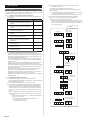
(4) Press and hold the “CHECK” button again for more than 3 seconds.
9. TEST OPERATION
•
The Check run will start.
In the Check run, the following items will be checked.
1 The wiring and piping between the indoor units and the Branch box
9. 1. Check run
2 Valve opening
After performing the repairs, inspections etc., always carry out the Check run. Normal
operation will not be possible without performing the Check run.
9. 1. 1. Things to confirm before starting the Check run.
To ensure safety, check that the following work, inspections and operations have
been completed.
Check Item
Check Column
1 Check that all work on the piping connecting the
outdoor unit, indoor units and branch box has been
completed
•
To make an enforced stop, press the “MODE/EXIT” button. You cannot
execute the stop operation using the remote control.
•
To prevent electric shock, close the service panel during the Check run.
(5) The Check run will stop automatically after all items are completed.
When an error occurs, consult the following error display items.
Correct the error, and carry out the Check run again.
*
When the error display appears even though the measures for error are
taken, switch on the power again after turning off the power. When the
power is turned on again after turned off, wait approx. 10 minutes and
turn on the power again.
2 Check that all work on the wiring connecting the
outdoor unit, indoor units and branch box has been
completed
●
( : On,
3 Is there a gas leakage? (At pipe connections {flange
connections and brazed areas})
4 Is the system charged with the specified volume of
refrigerant?
7 seg.display
: Blinking,
○: Off)
POWER
MODE ERROR
(LED981) (LED982)
5 Is a breaker installed at the power supply cable of
outdoor unit and every Branch boxes?
6 Are the wires connected to the terminals
without looseness, and in accordance with the
specifications?
7 Is the 3-way valve of the outdoor unit open? (Gas
pipe and liquid pipe)
8 Is power supplied to the crank case heater for
more than 12 hours?
CHECK
(Press and hold for
more than 3 seconds.)
9 Has the power supply of the all indoor units turned
off? (Remote controller)
9. 1. 2. Restrictions applicable when performing the Check run
• When the Check run starts, all indoor units connected to the outdoor unit will
start to run automatically. During the Check run, you cannot check the operation
of the indoor units separately. After the Check run, check the operation of the
indoor units separately in normal operation.
[Example of 7 seg. display]
• The operable temperature ranges for the Check run are: external temperature
-15 to 46 ºC; room temperature for cooling 18 to 46 ºC; room temperature for
heating -15 to 37 ºC.
• In the check run, the conditioner will automatically switch between cooling and
heating depending on the external temperature and internal temperature.
If the external temperature or internal temperature is outside the above operable
temperature range, wait until the temperature is within the operable range and
then perform the Check run.
Number of
indoor units
Number of
branch boxes
CHECK
(Press and hold for
more than 3 seconds.)
• The Check run can be completed within 1 hour, but may take several hours
depending on the external and internal temperature conditions etc.
• Please do not conduct the Check run with all the windows in the room closed.
Otherwise the room temperature could get too low or too high.
• Depending on the difference of the room temperature of each room, a judgment
may be impossible.
(currently
operating)
Ex) Mode:Heat
8 Indoor units
9. 1. 3. Operating procedure for Check run
(1) Turn power on the outdoor unit, indoor units and branch boxes.
H:Heat
C:Cool
After the displayed number of “8888.” has been turned off, press the “CHECK”
button. (approximately 2 minutes)
(2) Press and hold the “CHECK” button for more than 3 seconds.
(3) The number of connected branch boxes and indoor units will be displayed
on the 7 seg. display. Check that the displayed number matches the actual
number of connected units. Do not perform the Check run if the displayed
number of units is in error. If the Check run was performed with the number
of units in error, check the state of the units and then perform the Check run
again.
1 If the displayed number of units matches the installed number, go to (4)
2 If the displayed number does not match the installed number, check the
following.
En-15
•
Are all the Branch boxes turned on? → Check that the Branch boxes
are turned on, and go to (4).
•
Are connection cables connected to all of the indoor units?
→ Turn of the power, connect the
Connection cable and go to (1).
(operation has finished
normally (without error))
MODE/EXIT
(Press the MODE/EXIT button.
“END” has been turned off.)
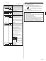
9. 1. 4. Error display
●: On,
(
Error display
7 seg. display
(blinking)
LED lamp
: Blinking,
○: Off)
Contents
[Indeterminable]
The external or room temperature is outside
the operable range. The air conditioner will
temporarily permit normal operation, but the
Check run should be carried out again at a
later date when the temperatures are within
the operable ranges.
[Wiring number error]
The number of wirings between indoor unit
and branch box is not correct. Turn off all
the units, and check number of connected
wires. After correcting the error, turn on the
power and carry out the Check run again.
[Pipe number error]
The number of wirings between indoor unit
and branch box is not correct. Turn off all
the units, and check number of connected
pipes. After correcting the error, turn on the
power and carry out the Check run again.
If the number of pipes is correct, the
internal heat-exchanger thermistor or branch
box piping thermistor may have come out of
its holder, or a coil may have come out of an
expansion valve. In this case, please contact
Service personnel.
(example)
9. 2. TEST RUN
9. 2. 1.
Pre-test run check items
Before the test run, refer to the figure and check the following items.
1 Is check run performed? Test run doesn't operate if check run is not performed.
(“FAIL” is displayed when operating the unit before the check run is done.)
After checking that the above items are all in order, refer to
“9.2.2. Test run method” to test run the unit.
If there are problems, adjust immediately and recheck.
9. 2. 2. Test run method
Be sure to configure test run settings only when the outdoor unit has stopped
operating.
• Depending on the communication status between the indoor and outdoor units,
it may take several minutes for the system to start operating after settings for
the test run are complete.
• After the test run settings are complete, all the outdoor units and the connected
indoor units will start operating. Room temperature control will not activate
during test run (continuous operation).
• Test run set with the outdoor unit doesn't stop automatically. Be sure to stop the
operation according to the operation method.
• All indoor units will operate when test run is performed from the outdoor unit. At
this time, the remote controller of the indoor unit is unavailable.
• Operation mode cannot be changed during the test run. To change the
operation mode, please stop the test run first, and then perform the test run
again. At this time, the compressor cannot be restarted for 3 minutes after it
stops in order to protect the indoor unit. Please restart it after 3 minutes.
[Wiring error]
A wiring error has occurred.
The location at which the wiring error has
been determined will be displayed on the 7
seg. display. If there are multiple wiring error
locations, the display will cycle through the
locations, switching every 2 seconds. After
performing the following operation, turn off
the power and correct the wiring.
• Note down the content of the wiring error.
• Note down the number of blinks of the
green LED on the PCB of the branch box.
(The number of blinks indicates the device
number of the Branch box)
After correcting the wiring, turn on the power
and carry out the Check run again.
(In the case of the diagram)
Connect the Connection cable which is
connected to the terminal A on Branch box
(Primary) to the terminal B on Branch box
(Secondary2).
1: Branch box-Primary
2: Branch box-Secondary 1
3: Branch box-Secondary 2
A: Branch box-Terminal A
b: Branch box-Terminal B
C: Branch box-Terminal C
[unit error]
This is a unit error.
* For error content, please refer to “11.2.
Error display mode”.
En-16
Perform test run for refrigerant system.
You can set “cooling test run” or “heating test run” with the push-button switch on the outdoor unit print circuit board.
Test run setting method
Function settings
First 2 digits Last 2 digits
MODE/EXIT
: Press the “MODE/EXIT” button.
MODE/EXIT
SELECT
: Press the “SELECT” button.
ENTER
: Press the “ENTER” button.
(Blinking)
SELECT
(Blinking)
SELECT
(When [F4] to [F9] are displayed, continue to press the
SELECT button until [F3] is displayed.)
ENTER
Settings for starting
test run operation
(Blinking)
SELECT
SELECT
For heating operation, press the SELECT
button until “01” is displayed.
For cooling operation, press the SELECT
button until “00” is displayed.
(Blinking)
ENTER
Press the ENTER button for more
than 3 seconds.
(Blinking)
ENTER
Press the ENTER button for more
than 3 seconds.
This will be displayed when the
cooling test run starts.
(It takes approximately 30 seconds for
the outdoor unit to start its operation.)
This will be displayed when the
heating test run starts.
(It takes approximately 30 seconds for
the outdoor unit to start its operation.)
This will be displayed
after 5 seconds.
This will be displayed
after 5 seconds.
(Blinking)
(Blinking)
SELECT
SELECT
Settings for stopping
test run operation
(Blinking)
(Blinking)
ENTER
ENTER
Press the ENTER button for more
than 3 seconds.
Press the ENTER button for more
than 3 seconds.
This will be displayed when the heating
operation mode is canceled.
This will be displayed when the cooling
operation mode is canceled.
(It takes approximately 30 seconds for
the outdoor unit to stop its operation.)
(It takes approximately 30 seconds for
the outdoor unit to stop its operation.)
This will be displayed
after 5 seconds.
This will be displayed
after 5 seconds.
(Blinking)
(Blinking)
MODE/EXIT
EXIT
After the test run is complete, turn off the power. Attach the cover of the electrical component box and the front panel of the outdoor unit.
En-17
9. 3. Confirming the operation of indoor unit
Run the unit in a normal way, and confirm its operation. (Please end the check run
first before confirmation)
① Cold air (or warm air) must be discharged from the indoor unit.
② The indoor unit operates normally when air direction or air volume adjustment
button is pressed.
Error code is displayed when operating the indoor unit with the remote controller
before check run.
10. 2. 2. Low noise mode (CN931)
• This features reduces the operating sound of the outdoor unit from the
normal sound. The air conditioner is set to the “Low noise mode” when
closing the contact input of a commercial timer or ON/OFF switch to a
connector on the outdoor control PC board.
* Performance may drop depending on the outside air temperature
condition, etc.
* Set the “Low noise mode” level, refer to “8.2. Function settings”.
Input Signal ···ON : Low noise mode
···OFF : Normal operation
10. EXTERNAL INPUT & OUTPUT
Input Signal
ON
10. 1. Fitting cable (optional parts)
OFF
The cable (including connector) that connects to the external input & output terminal is
an optional part.
This cable should not be laid parallel to the connection cable or power supply cable.
Doing so could result in erroneous operation.
Low noise mode
ON
OFF
10. 2. 3. External input priority mode (CN932)
• It is possible to switch to cooling operation and heating operation by
using external input.
* Set the “External input priority mode”, refer to “8.2. Function settings”.
Input Signal ···ON : Heating operation
···OFF : Cooling operation
Input Signal
ON
OFF
Priority mode
①
2
cable
When fitting the service cover,
pull the cable as shown in
the diagram to prevent it from
being trapped.
And fix the 2 binders
(accessory (optional parts)).
3
②
Fix the Binder (accessory (outdoor unit)).
③
Pass the cable through the as yet unused knockout hole.
(Please protect the cable with the edge of knockout hole to avoid damage.)
Seal the knockout hole that passes the cable with putty, so that there is no gap.
Heating
Cooling
10. 2. 4. Peak cut mode (CN933)
• Operation that suppressed the current value can be performed by
means of the connected unit. The air conditioner is set to the Peak cut
mode by applying the contact input of a commercial ON/OFF switch to a
connector on the outdoor control PC board.
* Set the “Peak cut mode” level, refer to “8.2. Function settings”.
Input Signal ···ON : Peak cut mode
···OFF : Normal operation
10. 2. External input
Input Signal
ON
10. 2. 1. Wiring of connector
ON/OFF of the “Low noise mode”, “External input priority mode”, “Peak cut
mode”, and “Stop operation mode” functions can be enabled with an external
field device.
When installing connection cable, specified part (optional parts) must be used.
Refer to section 8.2, Table. A: List of setting, for the required function. The
function must be set for the external input to work.
Input
Connector
Low noise mode
CN931
External input priority mode
CN932
Peak cut mode
CN933
Stop operation mode
CN934
Circuit diagram example
Peak cut mode
ON
OFF
10. 2. 5. Stop operation mode (CN934)
• It is possible to switch to Batch stop or Emergency stop and Normal
operation by using external input.
* Set the “Batch stop” or “Emergency stop” pattern, refer to “8.2. Function
settings”.
• When function setting is “Batch stop” mode
On
Input signal
Connected unit
(Field supply)
Outdoor unit
control PC board
OFF
Ex.) Switch
Off
Operation
Indoor unit
Stop
1
On
Remote controller
CN931
2
1
CN932
2
Connection cable (option)
• When function setting is “Emergency stop” mode
On
*10 m
1
Input signal
Indoor unit
2
1
CN934
Off
Operation
Signal
CN933
On
Connector
2
Remote controller
Stop
On
On
On
* Make the distance from the PC board to the connected unit within 10m.
• Contact capacity : 24VDC or more, 10mA or more.
En-18
10. 3. External output
11. LED Display
10. 3. 1. Wiring of connector
You can determine the operating status by the lighting up and blinking of the LED lamp.
Check the status using the table below.
When installing connection cable, specified part (optional parts) must be used.
Output
Connector
Error status
CN951
Compressor status
CN952
11. 1. Normal operation mode
C
H
Circuit diagram example
Outdoor unit
control PC board
Connection
cable
Connected unit
(Field supply)
Connector
1
Vcc
+
Vcc
Power
supply
CN951
2
+
Load
1
-
CN952
*10 m
2
Signal
* Make the distance from the PC board to the connected unit within 10m.
CODE
L
t
o
d
P
L
DESCRIPTION
Cooling
Heating
r During oil recovery operation
F During defrosting operation
C During power saving operation
n During low noise operation
11. 2. Error display mode
• When error occurs, “Err” and “Number of errors occurred” are alternately displayed
on the 7 seg. display.
• The latest error code can be confirmed by pressing the ENTER button.
• When error codes are displayed, all the error codes can be confirmed by pressing
the SELECT button.
• When the error display appears even though the measures for error are taken,
switch on the power again after turning off the power. When the power is turned on
again after turned off, wait approx. 10 minutes and turn on the power again.
1) Power supply
• Voltage (Chart sign=Vcc) : DC 24V or less
2) Load
• Load : DC 500mA or less is recommended
Example: When “Discharge thermistor error” and “Compressor thermistor error”
occurred
10. 3. 2. Error status output (CN951)
SELECT
: Press the “SELECT” button.
ENTER
: Press the “ENTER” button.
An air conditioner error status signal is produced when a malfunction occurs.
Error status
Error
Normal
ENTER
Output signal
ON
OFF
10. 3. 3. Compressor status output (CN952)
SELECT
Compressor operation status signal is produced when the compressor is
running.
Compressor status
Operation
Stop
Output signal
ON
OFF
10. 3. 4. Base heater
When installing connection cable, specified part (optional parts) must be used.
This output signal is produced when the outdoor temperature drop down to
2°C, and releases at 4°C.
Circuit diagram example
connected unit
P.C.B
1
2
CN206
AC240V
Base heater
*2
3
4
Connector
*1
connected unit
P.C.B
1
CN206
2
AC240V
Base heater
*3
3
4
Connector
*1
*1: Connect to pin 1 and pin 3. No connection pin2 and pin4.
*2: The allowable power consumption is 25W or less.
*3: If a load greater than 25W is applied, a contactor or relay should be
used to operate and control the base heater.
En-19
E
E
E
E
E
E
E
E
E
E
E
E
E
E
E
E
E
E
E
E
E
E
E
E
E
E
E
E
E
E
E
E
E
E
CODE
1 1
1 1
1 5
2 1
2 2
2 4
2 4
5 U
6 2
6 3
6 4
6 5
6 A
7 1
7 2
7 3
7 4
7 5
7 7
8 2
8 2
8 3
8 4
8 6
8 6
8 6
9 4
9 5
9 7
9 9
A 1
A 3
A 5
J 2
DESCRIPTION
3
4
6
2
1
2
3
1
1
1
1
3
1
1
1
3
1
1
1
1
2
1
1
1
3
4
1
1
3
1
1
1
1
U
Serial communication error
Check run unfinished
Wiring mistake
Indoor unit capacity error
Connection unit number error (indoor unit)
Connection unit number error (branch unit)
Indoor unit error
Outdoor unit P.C.B. model information error
Inverter error
Active filter error, P.F.C. circuit error
Trip terminal L error
Display P.C.B. communication error
Discharge temp. sensor error
Compressor temp. sensor error
Outdoor unit Heat Ex. liquid temp. sensor error
Outdoor temp. sensor error
Suction gas temp. sensor error
Heat sink temp. sensor error
Sub-cool Heat Ex. gas inlet temp. sensor error
Sub-cool Heat Ex. gas outlet temp. sensor error
Liquid pipe temp. sensor error
Current sensor error
Discharge pressure sensor error
Suction pressure sensor error
High pressure switch error
Trip detection
Compressor rotor position detection error
Outdoor unit fan motor error
4-way valve error
Discharge temperature error
Compressor temperature error
Low pressure error
Branch boxes error
Note : Even if error is solved while displaying error codes, the 7 seg. display
continues to display the error codes. Please confirm the error has been
recovered by checking normal display.
7 seg. display:
㪈㪑
㪎㪑
㪃
㪃
㪉㪑
㪃
㪊㪑
㪏㪑
㪃
㪐㪑
㪃
㪝㪑
㪻㪑
㪃
㪜㪑
㫅㪑
㪃
㫆㪑
㪬㪑
㪃㪃
㪃
㫉㪑
㪋㪑
㪃
㪃
㪘㪑
㪃
㪃
㪟㪑
㪃
㪃
㪃
㫋㪑
㪃
㪌㪑
㪃
㪍㪑
㪙㪑
㪃
㪚㪑
㪡㪑
㪃
㪣㪑
㪪㪑
㪃
㪧㪑
En-20