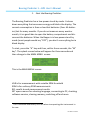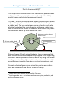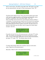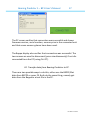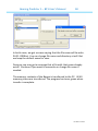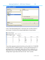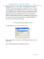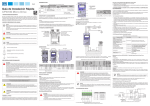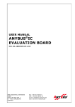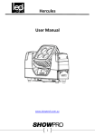
1
Bearing Predictor 1 – BP1 User’s Manual
1
Contents
Safety
What is it?
How is it done?
Getting started
EDM limits – GO/NO GO?
Rules of thumb – do they work?
KARMA AB, VÄLLINGBY, SWEDEN
Rev UK2 June 2014
Bearing Predictor 1 – BP1 User’s Manual
2
Welcome to a revolutionary new method to prevent
premature bearing damages – but do read this first!
Please..
Safety First!
You will be using the Bearing Predictor on rotating machinery and in
places where it is sometimes hot, cold, slippery, bad light conditions,
fumes, high noise levels and other safety hazards.
You will be using it in mines, on ships, in process industry, in workshops, in commercial and domestic buildings. In short: Everywhere!
There will be situations that we, that wrote this manual, cannot
always foresee. But we can foresee that ignorance, stress, “I shall
only..” and plain carelessness will cause accidents.
While the Bearing Predictor hardly can cause other accidents than
dropping it on your feet, the machinery you work on and the environment you work in can do so. So, please, make sure that you have
the proper safety training before attempting to do any measurements in field or in the lab. Many organizations have their “Safe
Employee” or similar training sessions. Do not try any measurements before you have had that training!
Rev UK2 June 2014
Bearing Predictor 1 – BP1 User’s Manual
3
Now – What is it?
The Bearing Predictor (short name: Beppe) is an instrument that
allows you to detect electric activity in bearings so you can apply
countermeasures to avoid premature bearing damage caused by
electric stray currents.
It does so from the very first minute after you have started that
pump, fan, machine-tool, elevator, printing press, ship propulsion,
paper machine or whatever the motor is used for. So, you do not
wait until vibration analysis – or worse, your ear – tells you that the
bearing is bad. You use the Beppe to PREDICT bearing failures.
That’s why it is called a Bearing Predictor.
Any bearing where Beppe says that you have excessive shaft peak
voltage or where Beppe detects oil film break-down is at risk. And by
employing standard mitigation techniques, you can avoid costly
future bearing failures.
Beppe can then be used in routine maintenance to make sure that
your grounding brushes, bonding straps or filters continue to do
their job. That is vital for the machinery’s availability – a failing shaft
grounding device or cracked ferrite ring is like having a small hole in
the ceiling; the damage can go on for years and cause big problems
if not detected and taken care of in time. Include regular shaft voltage and EDM measurements in your maintenance schedule for better availability of your machinery.
Rev UK2 June 2014
Bearing Predictor 1 – BP1 User’s Manual
4
How is it done?
In short: By detecting and counting shaft voltage break-downs. Every
break-down causes an electric discharge in the bearing and every
discharge creates a tiny crater in the ball and in the races. When
enough craters have formed, the bearing does not work any more.
There is a lot more to be said about this. Go to www.gke.org and
click Downloads. The downloads page is being updated continuously
– visit regularly for new documents and reports.
The discharging is very similar to Electric Discharge Machining and
the Beppe detects these discharges, the EDM events. It classifies
them in energy levels and accumulates them in counters. Too many
EDM events in one second mean that the bearing is at risk. And
more so when the EDM events occur at higher energy levels.
Beppe also detects potentially damaging voltage peaks that do not
result in EDM events, but can do so if the grease (or oil) gets hotter,
or if the shaft radial or axial load increases, or if speed changes. All
these changes influence the oil film thickness so that a voltage peak,
that does not damage the bearing today, may do so tomorrow.
For the curious: EDM events are detected by checking for fast voltage changes. A typical breakdown is from ±7 – 15 volts and is over in less than 100 nano-seconds, usually in no more than
30 ns. Light, fastest “animal” in the Universe, moves no more than about ten yards in 30
nanoseconds. That is why a coaxial cable and a termination device are used. Standard cables
do not work very well at these speeds. If you need to use longer cables, please contact GKE at
[email protected] for directions and tips. There is also the home-page www.gke.org where more
documents can be found. It is being updated continuously – visit regularly to stay informed!
Rev UK2 June 2014
Bearing Predictor 1 – BP1 User’s Manual
5
Getting started
This section describes how to:
1. Start the Bearing Predictor.
2. Connect to machine ground.
3. Connect to the motor or machine shaft.
4. Make EDM measurement.
5. Store results.
6. Recall results.
7. Switch Bearing Predictor off.
Results can be transferred to your PC.
To do so, please read the following sections:
8. Install USB driver and Beppe Manager program on your PC.
9. Start Beppe Manager program, connect PC to Beppe.
10. Transfer data from Bearing Predictor to PC.
11. Disconnect Bearing Predictor from PC.
The Bearing Predictor is self-explanatory with operator being guided
by cue texts on the display. But, to get the most out of the instrument and understand all aspect of its use, it is wise to study the
following pages and try out the operations. Do that – and you can
leave the operator’s manual behind when you go to do the measurements.
Rev UK2 June 2014
Bearing Predictor 1 – BP1 User’s Manual
6
1. Start the Bearing Predictor.
The Bearing Predictor has a low-power stand-by mode. It closes
down everything that consumes energy and blanks the display. The
current consumption is then so low that batteries ( four AA batteries) last for many months. If you do not measure every week or
month, it is a good idea to open the battery compartment and disconnect the batteries. When the Beppe is in low-power stand-by
mode (most people would say “OFF”), you don’t see anything but a
blank display.
To start, press the “A” key and then, within three seconds, the “M”
key1. The splash screen below will appear for three seconds and
then change to the MAIN MENU screen.
This is the MAIN MENU screen:
VAR is for measurement with variable EDM threshold
EDM is for ordinary EDM measurements
RCL recalls stored measurement results
SET opens menus for selecting language, connecting to PC, checking
software version, clearing memory, switching off and more.
1
This is to avoid involuntary turn on when transporting the instrument in
its case.
Rev UK2 June 2014
Bearing Predictor 1 – BP1 User’s Manual
7
That’s all there is to it. The Beppe is up and running. Waiting for
your commands.
2. Connect to machine ground.
The Bearing Predictor measures shaft voltage. Shaft voltage is the
voltage across the bearing. So, you need to connect to motor (or
machinery) frame and shaft. And, it is important that the connection
is made to the frame – not to just any ground that happens to be
convenient. This is because of the very fast voltage edges. You will
get all sorts of errors if you connect to a ground bus-bar or (don’t
even think about it) to mains ground.
Motors are painted. And that paint is very tough. So, it is usually not
possible to clip an alligator clip to the motor frame and get a good
ground connection. The ground connectors are usually placed either
inside the “pecker box” or centrally on the motor – which means far
away from the shaft. Actually, there is usually no convenient ground
connection on motors bigger than about 30 – 40 kW.
This is where the black accumulator clip shall be used. It grips almost
any mounting bolt’s head and it has a little “eye” where the black
alligator clip can be connected.
An alternative is to use one of the tiny magnets with an M3 screw
on. Rub the magnet against a paint-free surface and connect the
black alligator clip to the screw. It is good practice to measure that
there is a low ohm contact between M3 screw and motor frame
before proceeding with any measurement.
Rev UK2 June 2014
Bearing Predictor 1 – BP1 User’s Manual
8
3. Connect to the motor or machine shaft.
Danger! Rotating parts!
Possible high voltage!
Most electric motors are horizontally mounted with a shaft and
coupling that connects to the driven machinery. And then, there is a
protective cover that makes any contact with the shaft almost impossible. Stopping the machine for removal of cover is not always an
option. So, other ways have to be found.
One way is to use the non-drive end and locate the center bore in
the shaft. This center bore can usually be contacted using an insulated copper wire with insulation removed the last few millimeters.
This is usually a safe and good way of contacting the rotating shaft.
But, sometimes, there is an encoder or other transducer attached to
the NDE shaft. And sometimes, there is no center hole in the fan
guard grid. So, the shaft is not possible to contact.
One very good solution to most of these problems is to use a socalled KC Attachment (KCA). It is simple, easy, risk-free and reliable.
See description on next side.
There is also a risk that the motor shaft has a high voltage coupled
to it. This risk is very real on motors with insulated bearings and
when the shaft is connected via an insulated coupling or pulley and
belt. Measure with volt-meter or test with lamp before approaching an unknown motor where high shaft voltage can be expected!
Rev UK2 June 2014
Bearing Predictor 1 – BP1 User’s Manual
9
The KC Attachment (KCA)2
This simple and brilliant solution to the shaft contact problem needs
nothing more than an uninsulated wire and a rubber band. But,
mostly, a more sophisticated arrangement is used.
The idea is to let an uninsulated wire contact the shaft over a certain
angle and keeping the contact force stable with the aid of a spring or
a rubber band. The long contact area assures a low-ohm and stable
electrical contact and the small dimension of the wire makes it possible to use the KCA in almost all situations – even where the protective cover runs almost up to the motor end shield.
Make sure rotation doesn’t
stretch spring!
Spring or rubber band
Uninsulated wire
Picture showing KCA with uninsulated wire. Hooks are magnet feet
with insulated hooks or simple plastic clips clipped to the supporting
structure – ordinary insulated hook-up wire or any string can also be
used. If wire is insulated, then any tie-point can be used – insulated
or not. Remove insulation from wire on section that contacts shaft.
Connect red wire alligator clip to uninsolated part of wire and connect BNC connector to the Bearing Predictor. Ready3!
2
Named after Kjell Carlsson at Pharmadule Emtunga
Anything can be used – a simple screwdriver or anything conducting and
with an insulated handle.
3
Rev UK2 June 2014
Bearing Predictor 1 – BP1 User’s Manual
10
4. Make EDM measurement and 5. Store results.
Now, start the motor and run at the speed that you want to measure EDM at4.
Press the “B” button, under the EDM text. That will start an automatic measurement of EDM activity. The display looks like this when
measurements start:
Everything is OK, probe contacts the shaft, so press “OK”. The display changes to:
Measurement starts with PPS (Pulses Per Second) and since this is
the first measurement after start, the measurement number is 1.
As measurements proceed, the display shows the result:
In this case, there was no EDM activity in the bearing, so all energy
levels (High, Middle, Low5) show 0 PPS. That is excellent and seldom
4
Not always possible. Most motors run at process speed – then measure at
that speed.
5
H: 20 V, M: 10 V, L: 5 V. The discharge energy is proportional to voltage
squared. H produces four times more damages than M and sixteen times
more than L.
Rev UK2 June 2014
Bearing Predictor 1 – BP1 User’s Manual
11
seen in real motors. The little arrow above the “M” button says that
you can proceed with next part of the measurement. Press “M”!
The Peak Value display shows. Here, the positive peaks were small
(+1V) and the negative peaks are still being measured. After measurement is complete, the arrow shows again. Press “M”!
Now, the EDM measurements for measurement position number 1
is complete. The measurement results are still stored in the working
memory of the Bearing Predictor, but you may want to store them
more permanently for later transfer to your PC. So next screen is a
question that allows you to either store or ignore the latest measurement. Like this:
If you do not want to store this measurement, just press “B” under
“NO”. The display acknowledges your choice and returns to main
menu. If you, on the other hand, wants to store the measurements,
you press “A” under “OK”. The display shows shortly:
To verify that storage takes place and then returns to the main
menu. Ready for next measurement.
About the “DELAY” item in the measurement menu
Rev UK2 June 2014
Bearing Predictor 1 – BP1 User’s Manual
12
More often than not, you need three hands. One to keep the probe
in place, one to cling to whatever scaffolding or ladder there is and
one hand to press the “OK” button.
Beppe supplies that third hand for you!
Simply press “DELAY” and the measurement starts in ten seconds –
you will have plenty of time to put the probe in place while the display counts down and then starts the measurement. It looks like
this:
Measurement starts when 0 seconds have been reached.
There are two options under the SET/EDM menu; Stop or Continue.
Select “Stop” if you need to read PPS values before Peak values are
read. Select “Continue” if you do not want to press the “M” button
to continue with Peak measurements after PPS measurements.
6. Recall results.
When all measurements have been taken in that hot, humid, noisy,
dirty factory, it is nice to be able to sit down in your quiet, cool and
clean office to analyze the results.
You do this by recalling the memory contents in a few easy steps:
Press “A” and then “M” to start the Bearing Predictor
After splash screen and in MAIN MENU, press “C” button (under RCL
– RCL means Recall, of course).
The Recall screen shows, like this:
Rev UK2 June 2014
Bearing Predictor 1 – BP1 User’s Manual
13
First row says that this is memory number 1.
Second row says that these are peak values, zero volts, both positive
and negative.
Third row allows you to step up and down in memory and also to
change display between Peak and PPS results.
The arrow above “M” takes you back to the MAIN MENU (yes, “M”
usually stands for “Menu” or “More”).
Pressing “B” changes the display to the PPS display:
First row says that these are PPS values in Memory number 1. It also
shows that the High Energy Pulses Per Second (PPS) were zero.
Second row shows PPS for Medium and Low Energy. Both are zero.
Third row as usual – only that it switches to Peak.
There are 40 memory places available. It sounds like a limitation, but
you can rest assured that no one has, so far, been able to do more
than half so many measurements in one day. So it should be ample.
Transferring data to your PC after each day’s work further reduces
the need for many memory places.
7. Switch Bearing Predictor off.
There is no “OFF” switch on the front or top/bottom panels. This is
for one reason: Switches get damaged when hitting steel grating,
shafts or just about anything that it can hit in an industrial environment. So, no OFF switch.
Rev UK2 June 2014
Bearing Predictor 1 – BP1 User’s Manual
14
You switch off from the front panel. If you are in the Main Menu, it
is easy: Just press “M” (under SET) and get the first SETUP MENU.
There, above “A” is the OFF text. Press “A” and the display goes
blank.
What if you are in any other menu? Easy! Just press “M” (for Menu)
and you are there. Then press SET to reach the OFF function.
About OFF, current consumption, battery low and battery change.
Current consumption is extremely low when the instrument has
been switched off. It is also quite low when active and waiting for a
key to be pressed – something like 250 µA. It is only in some measurement situations that current consumption increases to about 25
mA. And then only for the duration of the measurement – like when
doing EDM and Peak measurements. So batteries should last several
years in normal use.
There are two situations where current consumption is continuous
and that will empty the batteries in a few days. That is when using
the Variable Level EDM check and when communicating with the PC.
The VarLevel operation is not described in this “Get Started” section
and is only used in certain cases. The VarLevel mode is used to check
actual EDM levels and is useful for detailed measurements. But
don’t leave the instrument in VarLevel mode when you are done
with the measurements.
When you have connected the Bearing Predictor, make sure that
you also disconnect (Section 11 of this manual) so that you do not
drain the batteries.
Rev UK2 June 2014
Bearing Predictor 1 – BP1 User’s Manual
15
When batteries go low, the display gets dimmer and dimmer. But
memory and measurement functions are intact also when the display cannot be read any more. That is because the display needs
about 5 volts to work while the processors (yes, there are two of
them) work happily with 3.3 volts supply.
But, you cannot use the instrument when the display can’t be read.
So, change batteries before it goes completely blank.
8. Install USB driver and Beppe Manager program on your PC.
Warning! Do not connect the USB cable to your PC
before you have installed the USB driver!
Locate these two files on the CD:
Run the USB driver CDM 2.02.04 (later versions may exist on your
CD).
Run setup.exe. It installs the Beppe Manager in a library of your
choice. The program icon looks like this:
9. Start Beppe Manager program.
Double-click the bepman icon.
Rev UK2 June 2014
Bearing Predictor 1 – BP1 User’s Manual
16
Now, connect the USB cable delivered together with the Bearing
Predictor. Make sure that both connectors are firmly seated.
Prepare the Bearing Predictor for PC communication by selecting
SET/PC. The display shows “CONNECTING” and waits for the PC to
connect. You can abort this mode by pressing any key. The Beppe
also aborts automatically if no connection was made in thirty seconds.
Select BEPPE/Connect.
Or press F7.
The PC connects to Beppe. PC screen and Beppe display then look
like this:
Rev UK2 June 2014
Bearing Predictor 1 – BP1 User’s Manual
17
The PC screen verifies that connection was successful and shows
firmware version, serial number, memory size in the connected unit
and that seven memory places have been used.
The Beppe display also verifies that connection was successful. The
two arrows are used to disconnect (press simultaneously) if not disconnected from the PC (using Ctrl-F7).
10. Transfer data from Bearing Predictor to PC.
There are two possible ways to do this, either use the BEPPE/Get
data from BEPPE or press F9. Both do the same thing, namely get
data from the Beppe to a text file in the PC.
Rev UK2 June 2014
Bearing Predictor 1 – BP1 User’s Manual
18
In both cases, we get a screen saying that the file name will be edm04-21-2008.txt. You can change file name and directory at will. But
we keep the default name for now.
Doing so, we may get a message that a file with that name already
exists. Continue if you want to overwrite or change file name if
needed.
The memory contents of the Beppe is transferred to the PC. All 40
memory places are transferred. The progress bar turns green when
transfer is complete.
Rev UK2 June 2014
Bearing Predictor 1 – BP1 User’s Manual
19
If the “View downloaded data” is checked, the transferred data is
also shown. A section of the downloaded data is shown below.
These data represent electrical activity on the shaft of a 2.2 kW 400
V motor fed from a PWM frequency inverter. Measurements # 1, 2
and 6 are taken at low speeds, where the oil film is rather thin, so
that EDM occurs at low voltages. Sometimes so low that the peak
voltage doesn’t get above the limit for the “Low” counter.
Rev UK2 June 2014
Bearing Predictor 1 – BP1 User’s Manual
20
Measurements # 3 – 5 are at 1000 – 1450 RPM and # 7 is taken at
650 RPM. These data are typical for a small 400 V motor. They are
not alarming, but it would definitely be better to see zeros, at least
in the “Middle” column. The data in the “Low” column are usually
not critical and there are motors running for years with many thousands PPS at 50 V, which is the level that “Low” is measured at.
Read more about typical EDM values in appendix “Are these data
OK?” It is also about time to have a look at the glossary at the end of
this manual. It contains many terms that are special to EDM, frequency inverters, motors and bearings.
11. Disconnect Bearing Predictor from PC.
Use BEPPE/Disconnect or Ctrl-F7 to disconnect.
USB communication is shut down and the Beppe display returns to
Main Menu.
Remove USB cable from PC and Bearing Predictor.
Rev UK2 June 2014
Bearing Predictor 1 – BP1 User’s Manual
21
EDM limits – GO/NO GO?
The Bearing Predictor’s main use is to find out if the
EDM level in a bearing is too high – or if it is safe. This
section of the manual is about evaluation of the PPS
and Peak Voltage measurements.
Since EDM activity depends on many factors, it is not
always possible to draw valid conclusions from one
single measurement. Some of the factors that influence the EDM readings are:
1. Rotational speed
2. Radial and axial bearing load
3. Bearing temperature
4. Grease presence and quality
Speed is important. It is generally not possible to get
any valid readings at speeds below 20 – 30 % of rated
speed. The reason is that the oil film has not yet developed, so that steel/steel contacts still exist in the
bearings. There can be no voltage and hence no discharge and no peak voltages to detect.
Operation at very high speed makes the oil film thicker
and therefore usually reduces discharge frequency so
that false ‘safe’ readings are obtained.
Always measure at representative operation speed.
Rev UK2 June 2014
Bearing Predictor 1 – BP1 User’s Manual
22
Forces on the bearing are important. Too much radial
or axial force reduces the oil film thickness. Measuring
an uncoupled motor (where no forces act on the bearing) can produce false ‘safe’ readings.
For reliable EDM measurements: Always measure with
motor coupled and with typical load.
Bearing temperature has a large influence on oil film
thickness and EDM voltage. A pump that handles fluids
ranging in temperature from a few °C to 80 °C will
show typical oil film break-down voltages between 40
– 50 V and a few volts. This does, of course, also influence the EDM measurements.
Therefore: Always measure when bearing has reached
normal operating temperature6.
Grease has much to say when it comes to EDM measurement. Lack of grease, or bad grease, makes
steel/steel more likely. It does not only reduce L10 life
– it also reduces EDM activity. A bearing that shows
safe EDM levels when measured can, after regreasing,
show high EDM levels.
Therefore: Always make sure that greasing is adequate before taking an EDM measurement.
When all these precautions have been taken, EDM
measurements are a reliable method to detect electrical activity in bearings and also makes a fairly accurate prediction of the individual bearing’s life time possible.
6
Bearings that operate under varying conditions need to be checked over
their entire temperature range.
Rev UK2 June 2014
Bearing Predictor 1 – BP1 User’s Manual
23
Rules of thumb – do they work?
Yes, mostly. Over the years, we have collected empirical data from many different installations and we now
know that bearings with more than 10 PPS at 20 V are
at risk. We also know that bearings with a few PPS at
20 and 10 V are safe and that several thousand PPS at
50 V can be tolerated. In tabular format:
20 V
10 V
5V
PREDICTION
<10 PPS
<10 PPS
<10 PPS
100+ PPS
1000+ PPS
<10 PPS
<100 PPS
<1000 PPS
ANY
ANY
ANY
ANY
ANY
ANY
ANY
RATED L10 LIFE
MANY YEARS
YEARS
1 – 2 YEARS
MONTHS
The prediction is valid for four-pole (1500/1800 RPM) induction
motors in the 11 – 1000+ kW range. For higher speeds, life is generally shorter.
Simple rule: Less than 10 PPS(H) and less than 100 PPS(M) is OK.
A typical measurement on pump motors in the 100 – 250 kW range
and running at around 1500 RPM is shown in the table on next page
(communication with customer in the Netherlands). There, the
number of PPS was quite high and bearing life very short. Fitting
common mode filters (Vacuumschmelze 250 F toroids) reduced
number of PPS to non-critical values.
Rev UK2 June 2014
Bearing Predictor 1 – BP1 User’s Manual
24
In this case, there were four motors with very short bearing life.
Under “Without Common-mode Filters”, the EDM measurements
were done before fitting common mode filters. No measurement
taken on motor number 1.
Under “With Common-mode Filters”, the EDM activity was measured after the common mode filters had been fitted. The filters reduce EDM effectively and it is only motor number 4 that still has a
somewhat high PPS number at 10 V.
It is expected that all these motors, except motor number 4, will
have bearing life corresponding to their nominal L10 life. If motor
number four fails after “MANY YEARS” (as the table says), one will
probably have to add another 250 F toroid to get below 100 PPS.
Adding a shaft grounding device (shorting brush) will also help.
A historical note
The original Bearing Predictor worked on analogue principles, where the
fast discharge was measured in volts per microsecond [V/µs]. The device
has been re-designed and now works along fully digital principles, which –
in short – means that the voltage change over 100 nanoseconds (0,1 µs) is
measured and counted. The rate-of-change is then 200 V/ µs from 20 V,
100 V/ µs from 10 V etcetera. There are some papers where the rate-ofchange is used instead of the now common voltage level. Translate 200 V/
µs to 20 V etcetera for comparison.
Rev UK2 June 2014
Bearing Predictor 1 – BP1 User’s Manual
25
NOTES
Rev UK2 June 2014