1
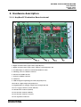
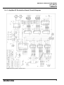
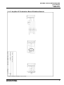
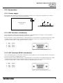
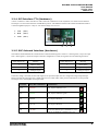
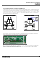
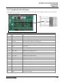
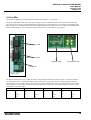
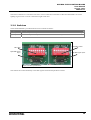
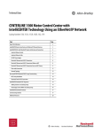
USER MANUAL
ANYBUS®IC
EVALUATION BOARD
DOC. NO. ABSICEVB-UM-1.01E
HMS INDUSTRIAL NETWORKS
GMBH
HAID-UND-NEU STR. 7
D – 76316 KARLSRUHE
GERMANY
TEL: +49 721 96472 0
FAX: +49 721 96472 10
e-mail: [email protected]
web: www.hms-networks.de
®
ANYBUS-IC EVALUATION BOARD
User Manual
Version 1.01e
2004-05-11
Revision Notes
Index
Date
Chapter
Autor
Revision
Revision note
1
2
2003-05-01
2003-10-21
All
5.2
Mat
Mat
1.0
1.01
Build
Tolerance for power supply updated
Preface
This document describes the technical features and usage of the AnyBus-IC Evaluation Board. The Evaluation Board
allows you to set up a complete development environment for creating applications which use the AnyBus-IC Module
with serial interface.
!
Please refer to the appendix for a list of supported AnyBus-IC modules.
The information and illustrations in this document are not binding. HMS reserves the right to make modifications and
changes if necessary.
HMS is not responsible for errors which are caused by incorrect information in this document.
AnyBus® is a registered trademark of HMS Industrial Networks AB.
Proprietary names and trademarks in this document are protected by law and belong to the respective owners.
HMS INDUSTRIAL
NETWORKS GMBH
2
ANYBUS-IC EVALUATION BOARD
User Manual
Version 1.01e
2004-05-11
Table of contents
Revision Notes ...................................................................................................................................................................2
Preface................................................................................................................................................................................2
Table of contents ...............................................................................................................................................................3
1. Introduction...............................................................................................................................................................4
1.1
Scope of delivery ................................................................................................................................................4
1.2
System requirements ...........................................................................................................................................4
1.3
Related documents ..............................................................................................................................................4
2. Hardware description ...............................................................................................................................................5
2.1.1
AnyBus-IC Evaluation Board external........................................................................................................5
2.1.2
AnyBus-IC Evaluation Board Circuit Diagram ..........................................................................................6
2.1.3
AnyBus-IC Evaluation Board Fieldbus Boards...........................................................................................7
2.2
Connectors ..........................................................................................................................................................8
2.2.1
Power supply...............................................................................................................................................8
2.2.2
MIF Interface (Hardware) ...........................................................................................................................8
2.2.3
SCI Interface RS232 (Hardware) ................................................................................................................8
2.2.4
SCI Interface TTL (Hardware)....................................................................................................................9
2.2.5
SSC Onboard Interface (Hardware) ............................................................................................................9
2.2.6
SSC expansion Interface (Hardware) ........................................................................................................10
2.2.7
AnyBus-IC DIL 32 Socket........................................................................................................................11
2.2.8
LEDs .........................................................................................................................................................12
2.2.9
Switches ....................................................................................................................................................13
2.2.10 Potentiometer ............................................................................................................................................14
2.2.11 Display ......................................................................................................................................................14
2.2.12 Reset Switch / SCI DE Jumper..................................................................................................................15
3. Simple StartUp ........................................................................................................................................................16
4. Master for fieldbus systems....................................................................................................................................17
5. Appendices...............................................................................................................................................................18
5.1
Sample Code .....................................................................................................................................................18
5.2
Technical Data ..................................................................................................................................................18
5.3
Abbreviations ....................................................................................................................................................19
5.4
Supported AnyBus-IC module types.................................................................................................................20
5.5
Recommended connector & accessory manufactures .......................................................................................21
Shift Registers...........................................................................................................................................................21
Power supply connector ............................................................................................................................................21
Power Supply ............................................................................................................................................................21
HMS INDUSTRIAL
NETWORKS GMBH
3
ANYBUS-IC EVALUATION BOARD
User Manual
Version 1.01e
2004-05-11
1. Introduction
This document will show the technical background of the connection between AnyBus IC and AnyBus IC Evaluation
Board. It’s strongly recommended to read chapter 3 “Simple StartUp” before using the AnyBus IC Evaluation Board.
Please contact our technical support department if you have any technical questions. Please refer to the end of the
appendix of this document for the address. The appendix also contains a feedback form which you should use if you
have any suggestions for improving this product.
1.1 Scope of delivery
Designation
Description
AnyBus-IC Evaluation Board
Development board for inserting an AnyBus-IC module. The board contains
all needed parts to communicate between a fieldbus system like Profibus,
DeviceNet or Industrial Ethernet and a serial connection with RS232 or direct
communication to I/O signal lines with shift registers.
1 Serial 1:1 cable
D-SUB9 socket <–> D-SUB9 plug
3 Fieldbus Adapter Boards
Adapter Boards with typical fieldbus connectors for connection to Profibus,
Devicenet and Ethernet
AnyBus-IC Tools CD-ROM
Contains:
AnyBus-IC User Manual
Example software
AnyBus-IC Design Guides, Fieldbus Appendix, technical drawings
Freeware Modbus/TCP Server
1.2 System requirements
Part
Requirement
IBM Compatible PC
min. Pentium I
Operating System
Windows 9X,ME,NT,2K, DOS, LINUX
Programm
Standard Terminal Programm (Hyperterm…)
Power Supply
5V DC, 800mA
AnyBus Fieldbus Module
AnyBus-IC for Profibus, DeviceNet or Industrial Ethernet
100 MHz, 32MB RAM, free RS232 Port with D-SUB9
1.3 Related documents
Name
Description
Document Number
AnyBus-IC Design Guide
General Engineering information for In-Design
of AnyBus-IC
ABS-DESIGN-SER
AnyBus-IC Appendix - Profibus
Data sheet for AnyBus-S Profibus-DP
ABS-APPENDIX-PDP
AnyBus-IC Appendix - DeviceNet
Data sheet for AnyBus-S DeviceNet
ABS-APPENDIX-DEV
AnyBus-IC Appendix - Ethernet
Data sheet for AnyBus-S Ethernet
ABS-APPENDIX-ETN
HMS INDUSTRIAL
NETWORKS GMBH
4
ANYBUS-IC EVALUATION BOARD
User Manual
Version 1.01e
2004-05-11
2. Hardware description
2.1.1 AnyBus-IC Evaluation Board external
14 15 16 1
2
3
4
5
6
13
7
8
Figure 1: AnyBus-IC Evaluation Board
12
11
10
9
1. Potentiometer for Analogue value (Input Byte #2)
2. Digital switch for binary input values (Input Byte #1)
3. Digital switch for binary input values/ Address switch (Input Byte #0)
4. SCI DE Jumper to enable SCI communication/Reset switch
5. Mounting screws for fieldbus connector
6. Interface for fieldbus boards
7. Socket for Fieldbus connector
8. AnyBus IC
9. LEDs for digital output/Diagnosis LED (Output Byte #0)
10. LEDs for digital output (Output Byte #1)
11. Digital display for analogue output values (Output Byte #2)
12. Power supply connector (5V DC, 800 mA)
13. MIF interface connector (RS232)
14. SCI interface connector (RS232)
15. SCI interface connector (5V TTL)
16. SSC Expansion connectors
HMS INDUSTRIAL
NETWORKS GMBH
5
ANYBUS-IC EVALUATION BOARD
User Manual
Version 1.01e
2004-05-11
2.1.2 AnyBus-IC Evaluation Board Circuit Diagram
Figure 2: Schematic of AnyBus IC Evauation Board
HMS INDUSTRIAL
NETWORKS GMBH
6
ANYBUS-IC EVALUATION BOARD
User Manual
Version 1.01e
2004-05-11
2.1.3 AnyBus-IC Evaluation Board Fieldbus Boards
Figure 3: Schematic of Fieldbus connector boards
HMS INDUSTRIAL
NETWORKS GMBH
7
ANYBUS-IC EVALUATION BOARD
User Manual
Version 1.01e
2004-05-11
2.2 Connectors
2.2.1 Power supply
The Evaluation Board must be connected to an external 5V/800mA power supply using a plugable screw connector.
Note that there is no over voltage protection implemented.
|
+
GND
+5V
Evaluation Board
Top View
Figure 4: Power supply connector front view
Figure 5: Position of power supply connector
2.2.2 MIF Interface (Hardware)
A PC is required to monitor and configure the AnyBus IC over the MIF Interface. See chapter 4 in the AnyBus-IC
Design Guide for more information regarding the terminal program.
The serial interface of the Evaluation Board is connected directly to a serial interface of an IBM compatible PC (COM1
– COMX) using the supplied cable. The RS232 interface already has crossed over Tx and Rx lines and thus the
connection is made with a 1:1 cable. The following pins are used:
1.
RxD
(Pin 2)
2.
TxD
(Pin 3)
3.
GND
(Pin 5)
Figure 6: Front view of D-SUB 9 female PC connector
2.2.3 SCI Interface RS232 (Hardware)
A PC or other RS232 Device is required to communicate to the AnyBus IC over the SCI RS232 Interface. See chapter 3
to learn more about the used ModbusRTU protocol.
The serial interface of the Evaluation Board is connected directly to a serial interface of an IBM compatible PC (COM1
– COMX) using the supplied cable. The RS232 interface already has crossed over Tx and Rx lines and thus the
connection is made with a 1:1 cable to the PC’s COM-port. The following pins are used:
1.
RxD
(Pin 2)
2.
TxD
(Pin 3)
3.
GND
(Pin 5)
Figure 7: Frontview of D-SUB 9 female PC connector
HMS INDUSTRIAL
NETWORKS GMBH
8
ANYBUS-IC EVALUATION BOARD
User Manual
Version 1.01e
2004-05-11
2.2.4 SCI Interface TTL (Hardware)
A micro controller or other serial device with UART can communicate to the AnyBus IC over the SCI-TTL Interface.
See chapter 3 to learn more about the used Modbus protocol. The difference between this and the SCI RS232 interface
is the missing RS232 physics. Only 5V TTL based voltage level is used.
1.
TxD
(Pin 1)
2.
RxD
(Pin 2)
3.
GND
(Pin 3)
Figure 8: SCI TTL based connector
1
2
3
2.2.5 SSC Onboard Interface (Hardware)
The ABIC Evaluation Board has a fixed amount of mounted shift registers. These are 3 shift registers (3 byte) for Input
and 3 shift registers (3 byte) for Output. If the auto configuration is used, the registers have the following functions:
Input Register Nr.
Meaning
Output Register Nr.
Meaning
1
Address setting
1
Status LEDs
2
Digital Input
2
Digital Output
3
Analogue Input
3
Analogue Output
If the auto config is not used, the first shift registers for input and output can also configured as digital Input/Output.
Please note that the output byte one is made with revers bi-colour LEDs. Thus pair bit combinations are not possible.
See chapter 2-6 in the AnyBus-IC Design Guide.
Hex-Value
Binary-Bit combination
Visualisation
0xAA
10101010
Yes, all pairs different: red
0x55
01010101
Yes, all pairs different: green
0x33
00110011
No, all pairs identical
0xFF
11111111
No, all pairs identical
0x78
01111000
No for the identical pair combination L1+L3,
Yes for the different combination L2+L4
HMS INDUSTRIAL
NETWORKS GMBH
9
ANYBUS-IC EVALUATION BOARD
User Manual
Version 1.01e
2004-05-11
2.2.6 SSC expansion Interface (Hardware)
Additional shift registers can be used to expand the amount of I/O data over SSC interface. The additional shift registers
can be mounted on a separate PCB connect to the SSC expansion interface. Please note that air wires may cause EMC
problems and act as antenna. JP6 is connected to all shift registers for load, reset and clock signal. JP 5 and JP 6 should
be short circuit by jumper if no external shift registers are connected. JP 5 is the serial connection for expanded input
shift registers. Same for JP 4 as output expansion.
No Additional Shift Registers
JP4
Additional Shift Registers
JP5
JP4
Input
Output
Input
Shiftregister
Output
Shiftregister
AB IC
Output Output
Shiftregister
SSC DI 1
Output
Output
Shiftregister
SSC DI 1
Input
Additional
Input
Shiftregiste
Input
Input
Shiftregister
AB IC
Input
Input
Shiftregister
Figure 10: No additional shift registers
Output Output
Shiftregister
Input
Input
Shiftregister
Figure 9: Additional Input shift registers
The SSC Interface connectors are used to expand the onboard mounted shift registers with additional external shift
registers. Please note that air wires may cause EMC problems and act as an antenna.
Figure 11: Position of SSC external connection
JP6 will extend the LD, CLK and RST lines. See chapter 226 for more information. JP4 and JP5 will extend the shift
register line for Input (JP4) and Output(JP5). Open the short circuit jumper and insert up to 14 8 Bit shift register
devices to extend to the maximum size of 128 Bit I/O data.
HMS INDUSTRIAL
NETWORKS GMBH
10
ANYBUS-IC EVALUATION BOARD
User Manual
Version 1.01e
2004-05-11
2.2.7 AnyBus-IC DIL 32 Socket
The AnyBus-IC DIL 32 Socket at the Evaluation Board is used to plug in the AnyBus-IC module. The pin assignments
are shown in following table:
Figure 12: Position of AnyBus-IC DIL Socket
Pin
Name
Description
1
Vcc
+5V Power Supply
2
SSC Reset Out
SSC Reset signal to shift registers
3
SSC LD
SSC Load signal to shift registers
4
SSC DO
SSC Data output signal to shift registers
5
SSC DI2
SSC Data input 2 signal from shift registers
6
SSC DI1
SSC Data input 1 signal from shift registers
7
SSC CLK
SSC Clock signal for shift registers
8
Reset
Reset signal
9
Vcc
+5V Power Supply
10 - 12
NC
Not connected
13 - 16
FB1 – FB4
Fieldbus specific signals line 1-4
17
PE
Protective earth
18
Shield
Fieldbus shield
19 - 20
FB5 – FB6
Fieldbus specific signals line 5-6
21 - 23
NC
Not connected
24
GND
Ground Power Supply
25
NC
Not connected
26
INT/BLE
Interrupt / Bootloader enable
27
MIF Tx
MIF transmit signal
28
MIF Rx
MIF receive signal
29
SCI DE
SCI DE signal
30
SCI Tx
SCI transmit signal
31
SCI Rx
SCI receive signal
32
GND
Ground Power Supply
HMS INDUSTRIAL
NETWORKS GMBH
11
ANYBUS-IC EVALUATION BOARD
User Manual
Version 1.01e
2004-05-11
2.2.8 LEDs
The Evaluation Board is provided with the following status diagnostic or data LEDs:
The power LED indicates that the 5V DC power supply is present. The MIF communication LED TxD flashes when
data is being sent to the PC. The LED RxD flashes when data is received from the PC. The LED SCI TxD flashes when
data is being sent to the ModbusRTU Master. The LED RxD flashes when data is being received from the ModbusRTU
Master. These LEDs are only for diagnostic purposes and cannot be controlled by your program.
SCI communication LEDs
Figure 14: Position of communication LEDs
MIF communication LEDs
Digital Data LEDs
Diagnostics/Data LEDs
Power LED
Figure 13: Position of
Diagnosis LEDs
The Digital Output Byte0, Byte 1 LEDs are used to show the digital status of the first two bytes, sent from the ABIC to
the shift registers. Byte 1 is made with 8 green LEDs. Each byte is representing one bit in the first data byte. Byte0 is
made with four bi-color LEDs. Because of the Bi-Color LEDs at Output Byte 0 and its pre-defined function as Fieldbus
Status diagnosis its not possible to transmit all possible data states to this LEDs. Only different binary values for bit-pair
combinations will show a light:
L4
00
11
01
10
nv
nv
green
red
L3
00
11
01
10
nv
nv
green
red
L2
00
11
01
10
nv
nv
green
red
L1
00
11
01
10
nv
nv
green
red
*nv=no visualisation
HMS INDUSTRIAL
NETWORKS GMBH
12
ANYBUS-IC EVALUATION BOARD
User Manual
Version 1.01e
2004-05-11
The reason is that 00 or 11 will cause a 0V-0V or 5V-5V connection to the LED. A Bi-Color LED needs a 0V-5V for
lighting in green color or 5V-0V connection to light in red color.
2.2.9 Switches
The Evaluation Board is provided with two micro switches as follows:
Designation
Description
Input Byte 0
First data Byte. In “Only SSC Mode” this is used as address or address/baudrate switch. LSB is right
Input Byte 1
Second data byte. In “Only SSC Mode” this is used as first data byte
Data/Address switch
Data switch
Input Shift register
byte 1
Input Shift register byte 0
Figure 15: Position of switch buttons
The switches are connected directly to the shift registers with internal pull down resistors.
HMS INDUSTRIAL
NETWORKS GMBH
13
ANYBUS-IC EVALUATION BOARD
User Manual
Version 1.01e
2004-05-11
2.2.10 Potentiometer
The potentiometer on the Evaluation Board is used to provide an analog signal for generating user data for data
transmission. The value set by the axis will demonstrate the incoming analog value that is converted by the A/D
converter and moved with the shift register into byte 2.
8 Bit A/D Converter
Input Shift register
byte 2
Data Potentiometer
Figure 16: Analog Input
2.2.11 Display
The Display is used to show the byte 2 value as analog data. The data from ABIC transmitted to the shift register in
output byte 2 is converted with the D/A converter into an 0-5V analog value. This value is connected to the display that
will show its voltage value.
8 Bit Shift register
byte 2
8 Bit D/A Converter
Data Display
Figure 17: Analog Output
!
If necessary, you can remove the LCD from the Evaluation Board and connect it using a cable of length < 10cm.
However, you will lose the manufacturer's guarantee if you do this.
HMS INDUSTRIAL
NETWORKS GMBH
14
ANYBUS-IC EVALUATION BOARD
User Manual
Version 1.01e
2004-05-11
2.2.12 Reset Switch / SCI DE Jumper (Only SSC Mode)
The Evaluation Board is provided with a hardware reset switch. Using this switch will cause a hardware reset on the
ABIC.
Near the switch is the location for BL/SCI DE switch. BL- (BootLoader) switch is only used for Bootloader enabling
function. Please see chapter 8-2 in AnyBus IC Design Guide. The BootLoader switch can be closed by using a jumper.
Same pin pair (1-3) is also used for detecting Interrupt requests. Pin 1 is GND and Pin 3 is the IRQ line.
The SCI DE switch is used for enabling the SCI communication interface. To enable the SCI-Interface the Jumper JP7
2-4 has to be removed. With short 2-4 pin the IC will detect the amount of shift registers and start automatically.
Reset Switch
Figure 18: Reset Switch/ Bootloader / Interrupt
Boot loader Enable/
Interrupt Request
HMS INDUSTRIAL
NETWORKS GMBH
SCI Data Enable
15
ANYBUS-IC EVALUATION BOARD
User Manual
Version 1.01e
2004-05-11
3. Simple StartUp
•
For a simple start up connection of the AnyBus IC it’s necessary to prepare the hardware and software
configuration. Please follow the steps to achieve the first communication:
•
check the jumpers
In a simple Startup 3 jumpers are needed: JP4;JP5 and JP7. JP4 and JP5 are used for closing the extended SSC
connection. JP7 will disable the SCI interface. All other jumpers must left open.
(see figure 11 and figure 18)
•
check the correct AnyBus IC connection
Don’t connect the AnyBus-IC reversed to the socket. The HMS logo must be close to middle of the Evaluation
Board (close to the capacitor C10, see figure 12)
•
Use the correct fieldbus connector
Use the fieldbus connector that match to the fieldbus system:
- 9 Pin SUB-D fieldbus connector together with AnyBus IC PDP
- Grey plugable Screw fieldbus connector together with AnyBus IC DEV
- RJ45 fieldbus connector together with AnyBus IC EIT/EIP
Other combinations can harm the AnyBus IC! Worst combination is PDP or EIT/EIP IC together with
Devicenet connector and connected 24V supply! This will destroy the AnyBus-IC!
•
Connect a PC to MIF
Use the serial 1:1 cable to connect the EVB’s monitor interface (MIF) to a PC’s COM port. Start a terminal
program like Microsoft’s Hyperterm with this settings:
- 38400 kBaud
- 8 databits
- 1 stopbit
- no parity
- no flowcontrol
•
Connect power to the Evaluation Board
We recommend to use a stabilized power supply with constant 5V±10% and a min. current of 800 mA .
Connect the Plus polarity cable to the pin close to the SUB-D connector for MIF. Connect the ground polarity
cable to the pin close to the lowest left corner. Please note that there is no over voltage protection
implemented. Wrong voltage level or reversed power supply can harm the Evaluation board and the AnyBus
IC.
The board is powered if the power LED is lighting. The menu for the configuration will be generated an transferred
to the terminal program. Depending on the fieldbus system the dual-LEDs at the first output byte will light. Also
the first input byte delivered by the first DIP-switches is used as address setting. See chapter 2 at the ABIC fieldbus
appendix.
You can use now the ABIC-Evalboard as a fieldbus slave with two byte input and two byte output data. The first
digital input data is “INPUT Byte 1” with DIP-switch and the first byte output is “OUTPUT Byte 1” with 8 green
LEDs. The data for the second byte input is delivered by the potentiometer in “Input Byte 2” and the second byte
output is shown at analogue values by the Display at “OUTPUT Byte 2”.
You can use a master system or a master simulator to transmit data from/to the AnyBus IC Evaluationboard.
Master simulators are available for Profibus-DP, Devicenet and ModbusTCP.
HMS INDUSTRIAL
NETWORKS GMBH
16
ANYBUS-IC EVALUATION BOARD
User Manual
Version 1.0e
2004-05-11
4. Master for fieldbus systems
When developing and testing programs for AnyBus-S modules, a master is required for the respective bus system. In
addition to standard SPS masters, HMS recommends the use of so-called master simulators. These are simple fieldbus
master systems with small limitations which simulate bus communication with the respective fieldbus system and allow
the exchange of data between master and slave. Master simulators are currently available for Profibus DP, Profibus
DPV1, DeviceNet and Interbus- S.
Figure 19: Profibus DP Master simulator
The supplied HMS CD-ROM also includes a simple freeware Modbus/TCP Server which can be used to test
communication between an AnyBus-S Ethernet module / AnyBus IC on the Evaluation Board and a PC. Please observe
the installation instructions!
Figure 24: Freeware Modbus/TCP Server
!
The supplied Modbus/TCP Server Software is demonstration software which is freely available in the Internet.
HMS cannot provide support for installation and commissioning.
HMS INDUSTRIAL
NETWORKS GMBH
17
ANYBUS-IC EVALUATION BOARD
User Manual
Version 1.0e
2004-05-11
5. Appendices
5.1 Sample Code
The sample code is included at the AnyBus-Tools CD-Rom.
Each program is prepared to run at the Keil C51 compiler environment and the AnyBus Evaluation Board. It is
downloadable with the monitor functionality described in chapter 4.4 at the Evaluation Board user manual.
For further questions and inspirations we have in the Club AnyBus an open ear for you any time .
http://www.hms-networks.com/club_anybus/club_area.asp
5.2 Technical Data
Measurement
PCB
Standard Euro Format: 160 mm x 100 mm
Possible Case
Phoenix Case UM100 125 mm x 162 mm
Complete height with connected AnyBus IC
app. 50 mm (depending from fieldbus type)
Recommended Power Supply
5V regulated ±10% Tolerance
ANYBUS-IC EVALUATION BOARD
User Manual
Version 1.0e
2004-05-11
5.3 Abbreviations
Important abbreviations used in this manual:
ABC
ABS
ACK
DPRAM
EVB;
EvalBoard
µC
LED
LSB
MSB
NAK
NC
PAR
RO
R/W
SER
TBD
AnyBus ComAdapter
AnyBus-S
Acknowledge
Dual-Port RAM
AnyBus-S Evaluation Board
Microcontroller (80XXX)
Light Emitting Diode
Least Significant Bit
Most Significant Bit
Negative Acknowledge
Not Connected
Parallel Interface
Read Only
Read / Write
Serial Interface
To Be Defined
ANYBUS-IC EVALUATION BOARD
User Manual
Version 1.0e
2004-05-11
5.4 Supported AnyBus-IC module types
The following AnyBus-S module types are suitable for use with the Evaluation Board. Special AnyBus-S module types
are also supported (but see note below the table).
Description
Order Nr.
Fieldbus Type
ABIC-PDP
AB6000
Profibus- DP
ABIC-DEV
AB6001
DeviceNET
ABIC-EIT
AB6002
10/100 Mbit/s ModbusTCP+IT Funct.
ABIC-EIP
AB6003
10/100 Mbit/s ModbusTCP+EthernetIP+IT Funct.
ABIC-COP
*
* in preparation
ANYBUS-IC EVALUATION BOARD
User Manual
Version 1.0e
2004-05-11
5.5 Recommended connector & accessory manufactures
Shift Registers
• 74AHCT594
• 74HCT165M
Europe
EBV EUROPEAN SERVICE
Im Technologiepark 2-8
D-85586 Poing, Germany
Tel.: +49 - 8121 - 774 - 0
Fax : +49 - 8121 - 774 - 422
Schweden
EBV EUROPEAN SERVICE
Derbyvägen 20
S-21235 Malmö, Sweden
Tel.: +46 - 40 – 59 21 00
Fax : +46 - 40 – 59 21 01
Headquarter
EBV EUROPEAN SERVICE
Im Technologiepark 2-8
D-85586 Poing, Germany
Tel.: +49 - 8121 - 774 - 0
Fax : +49 - 8121 - 774 - 422
Power supply connector
.
• 2 pins
Europe
Phoenix Contact GmbH & C0.
Flachsmarktstraße 8
32825 Blomberg
Tel.: +49 – 5235 – 300
Fax: +49 – 5235 – 341200
WEB: www.phoenixcontact.com
• 2,54 mm grid
Schweden
Headquarter
Phoenix Contact GmbH & C0.
Flachsmarktstraße 8
32825 Blomberg
Tel.: +49 – 5235 – 300
Fax: +49 – 5235 – 341200
WEB: www.phoenixcontact.com
Power Supply
.
• Wide range power supply
• 100 V-250 V Primary
• 5V Secondary
• Changeable connector for US,EU,JP...
Europe
RS Components GmbH
Hessenring 13b
64546 Mörfelden-Walldorf
Tel.: ++49 – 6105 – 401 – 234
Fax.: ++49 – 6105 – 401 – 100
WEB: www.rs-components.de
Schweden
RS Components AB
Box 15
162 11 Vällingby
Tel.: ++46 – 8 - 445 – 8900
Fax.: ++46 – 8 – 687 – 1152
WEB: www.rs-components.com
Headquarter
RS Components International
PO Box 99, Corby, Northants
NN17 9RS, United Kingdom
Tel.: ++44 – 1536 – 201234
Fax.: ++44 – 1536 – 204237
WEB: www.rs-components.com
ANYBUS-S EVALUATION BOARD
User Manual
Version 1.1
2004-05-11
If you have any comments about this documentation, please take a few minutes to fill out this form, and
let us know about your opinions. These comments will help us improve our work, and make us aware of
what customers of our products may find good, faulty or even missing.
Document title:_____
ABSICEVB-UM
1.01E
___________
Revision:
_____________________
_______________
Your name:
_____________________________________________________
Company:
_____________________________________________________
Phone:
_____________________________________________________
E-mail:
_____________________________________________________
Comments:____________________________________________________________________________
______________________________________________________________________________________
______________________________________________________________________________________
______________________________________________________________________________________
______________________________________________________________________________________
______________________________________________________________________________________
______________________________________________________________________________________
______________________________________________________________________________________
______________________________________________________________________________________
______________________________________________________________________________________
Send your comments to: HMS Industrial Networks GMBH
Haid-und-Neu Str.7
76131 Karlsruhe
Germany
You may also mail or fax your comments:
E-mail: [email protected]
Fax: +49 (0)271 96472 10