1
Installation
IGEMS Release 8
CAD/CAM/NEST
User Manual
2008-10-09
Page 1
Installation
Chapter 1. Installation ................................................................................... 7
Requirements ................................................................................................ 7
Step 1: Install the IGEMS-software ................................................................. 7
Step 2: Install Hardware lock driver ................................................................ 7
Step 3: Start IGEMS ....................................................................................... 8
Step 4: Restart IGEMS ................................................................................... 9
Floating License Manager ............................................................................... 9
Updates ...................................................................................................... 10
Chapter 2. General CAD functionality ............................................................ 11
Language and units ..................................................................................... 11
Zoom and Pan ............................................................................................. 11
Command line ............................................................................................. 12
Short keys ................................................................................................... 12
Coordinate input .......................................................................................... 12
Object snap ................................................................................................. 13
Distance input ............................................................................................. 14
Grid, Ortho and Snap mode .......................................................................... 15
Select objects .............................................................................................. 15
Automatic base point ................................................................................... 16
Undo and Redo ............................................................................................ 16
Chapter 3. Object creation ........................................................................... 17
Line (L) ....................................................................................................... 17
Point (Shift P) .............................................................................................. 17
Circle (C) ..................................................................................................... 18
Circle by 2 points ......................................................................................... 18
Circle by 3 points ......................................................................................... 18
Circle by 2 points and a Radius ..................................................................... 18
Ellipse ......................................................................................................... 19
Ellipse by center .......................................................................................... 19
Arc (A) ........................................................................................................ 19
Rectangle .................................................................................................... 19
Polyline ....................................................................................................... 20
Rectangle by X, Y and center ........................................................................ 20
Bounding box .............................................................................................. 20
N-Gon (Polygon) .......................................................................................... 21
Polyspline .................................................................................................... 21
Obround...................................................................................................... 21
Swell ........................................................................................................... 22
Text (Shift T) ............................................................................................... 22
Centroid ...................................................................................................... 22
Chapter 4. Object position ............................................................................ 23
Move (M) .................................................................................................... 23
Copy (Shift C) .............................................................................................. 23
Scale (S) ..................................................................................................... 23
Rotate (R) ................................................................................................... 24
Page 2
Installation
Mirror (Shift M) ............................................................................................ 24
Erase (E) ..................................................................................................... 25
Polar Array .................................................................................................. 25
Rectangular Array ........................................................................................ 25
Chapter 5. Modify objects ............................................................................ 27
Offset (O).................................................................................................... 27
Explode (X) ................................................................................................. 27
Trim (T) ...................................................................................................... 27
Extend ........................................................................................................ 28
Lengthen ..................................................................................................... 28
Fillet (F) ...................................................................................................... 28
Fillet zero .................................................................................................... 28
Chamfer ...................................................................................................... 29
Join (J)........................................................................................................ 29
Extended Join .............................................................................................. 29
Polyline editor .............................................................................................. 29
Edit text ...................................................................................................... 30
Create Region.............................................................................................. 30
Paste clipboard text ..................................................................................... 30
Delete (Del)................................................................................................. 31
Break .......................................................................................................... 31
Subtract ...................................................................................................... 31
Union .......................................................................................................... 32
Boundary trim ............................................................................................. 32
Chapter 6. Dimension command ................................................................... 33
Linear dimension ......................................................................................... 34
Radius dimension......................................................................................... 34
Diameter dimension ..................................................................................... 35
Angular dimension ....................................................................................... 35
Automatic dimension .................................................................................... 35
Chapter 7. Various commands ...................................................................... 36
Distance ...................................................................................................... 36
Info (I)........................................................................................................ 36
Parametric parts .......................................................................................... 36
Shape library ............................................................................................... 38
Chapter 8. Layers, colors and plotting ........................................................... 40
Layer (Y) ..................................................................................................... 40
Color ........................................................................................................... 41
Plot (Ctrl+P) ................................................................................................ 41
Plot limits .................................................................................................... 42
Chapter 9. File and Block handling ................................................................ 43
Open........................................................................................................... 43
Import drawing............................................................................................ 43
Paste from AutoCAD .................................................................................... 44
Save ........................................................................................................... 45
Export ......................................................................................................... 45
Page 3
Installation
Block ........................................................................................................... 45
Insert .......................................................................................................... 46
Save as template ......................................................................................... 47
Select a template ......................................................................................... 47
Purge .......................................................................................................... 48
Cut and Paste .............................................................................................. 48
Chapter 10. SignMaker option ........................................................................ 49
Font tracer .................................................................................................. 49
Image Tracer .............................................................................................. 50
Skew........................................................................................................... 51
Image ......................................................................................................... 52
Chapter 11. CAM-Tools option ........................................................................ 53
Clean Up ..................................................................................................... 53
Curve fit ...................................................................................................... 53
Vectorize ..................................................................................................... 54
Replace ....................................................................................................... 54
Edge fix ...................................................................................................... 54
Poly joint ..................................................................................................... 55
Contour analyzer ......................................................................................... 55
Boundary polygon ........................................................................................ 56
Chapter 12. The workflow in 2D-CAM ............................................................. 57
Step 1: Create the geometry ........................................................................ 57
Step 2: Create a part ................................................................................... 57
Step 3: Add toolpath .................................................................................... 58
Step 4: Add the cut-order ............................................................................. 59
Step 5: Postprocessing ................................................................................. 61
Chapter 13. Create toolpath ........................................................................... 62
The Auto command ..................................................................................... 62
The Single command ................................................................................... 64
The Quick command .................................................................................... 66
Manual ........................................................................................................ 67
Marking ....................................................................................................... 68
Chapter 14. Disconnected toolpath ................................................................. 70
Common cut line.......................................................................................... 70
Bridge ......................................................................................................... 71
Chain cutting ............................................................................................... 72
Scrap cut..................................................................................................... 73
Chapter 15. Various command ....................................................................... 74
The Hole command ...................................................................................... 74
HQCH High Quality Circular Hole ................................................................... 75
Disconnect toolpath ..................................................................................... 76
Break toolpath ............................................................................................. 76
Connect toolpath ......................................................................................... 77
Join Parts .................................................................................................... 77
Split part ..................................................................................................... 77
Lead settings ............................................................................................... 78
Page 4
Installation
Cutting Quality ............................................................................................ 80
Clone .......................................................................................................... 81
Restore geometry ........................................................................................ 82
Part text ...................................................................................................... 82
Part distance ............................................................................................... 83
Contour smoothing ...................................................................................... 83
Tool setup ................................................................................................... 84
Edit part ...................................................................................................... 85
Chapter 16. Cut order and Postprocessing ...................................................... 87
Sheet prepare (Cut order) ............................................................................ 87
Postprocessing ............................................................................................ 89
Chapter 17. Simulation and cost calculation .................................................... 91
Simulation ................................................................................................... 91
NC-Reader................................................................................................... 91
Estimate cost ............................................................................................... 92
Chapter 18. Sheet commands ........................................................................ 93
Create sheet ................................................................................................ 93
Part browser................................................................................................ 94
Lock sheet ................................................................................................... 95
Unlock sheet ............................................................................................... 95
Cavity sheet ................................................................................................ 96
Divide sheet ................................................................................................ 96
Analyze sheet .............................................................................................. 97
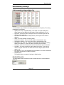
Chapter 19. Machine settings ......................................................................... 98
Common settings ......................................................................................... 99
Tools and Sheet setting ............................................................................... 101
Collision settings ......................................................................................... 102
Advance WaterJet Settings .......................................................................... 102
Cost setting ................................................................................................ 104
Chapter 20. Material setting .......................................................................... 105
Machinability settings .................................................................................. 107
Advance Water Jet Settings ......................................................................... 108
Laser Settings ............................................................................................. 109
Water, Gas and Plasma settings ................................................................... 110
Chapter 21. Shared folder and CAM-Settings .................................................. 111
Chapter 22. Nesting Level 1 .......................................................................... 112
Single nest ................................................................................................. 112
Quick nest .................................................................................................. 113
Rectangle nest ............................................................................................ 114
Chapter 23. Nesting Level 2 .......................................................................... 116
Chapter 24. Bevel cutting on standard parts................................................... 119
Bevel cut .................................................................................................... 119
Chapter 25. Bevel cutting on advance geometry ............................................. 121
Define Bevel part ........................................................................................ 121
Cut bevel part............................................................................................. 122
Process Bevel part ...................................................................................... 122
Page 5
Installation
Chapter 26. Tile Maker option ....................................................................... 124
Step 1: Generate the drawing ...................................................................... 124
Step 2: Tile nest ......................................................................................... 125
Step 3: Tile cut ........................................................................................... 127
Chapter 27. The Report system ..................................................................... 130
Chapter 28. New Report system .................................................................... 131
Dynamic document .....................................................................................131
Save and export ......................................................................................... 132
Design mode .............................................................................................. 132
Creating reports outside IGEMS ................................................................... 136
Chapter 29. Organizer module....................................................................... 137
Register ..................................................................................................... 137
Register a rest sheet ................................................................................... 138
View information......................................................................................... 139
Properties................................................................................................... 140
Profiles ....................................................................................................... 141
Insert parts and sheets ............................................................................... 142
The Organizer directory ............................................................................... 142
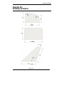
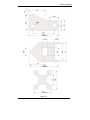
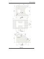
Chapter 30. Drawing examples ...................................................................... 143
Page 6
Installation
Chapter 1.
Installation
Requirements
Before you start the installation, be sure that you have a wheel mouse and a
computer with Windows 2000, Windows XP or Windows Vista. (Windows 98 and
Millennium is NOT supported). We recommend a processor with at least 500 MHz
and 512 MB of available system RAM. The software needs a hard disk space of
about 50MB. The faster computer you have, the more you will like to work with
IGEMS.
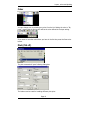
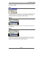
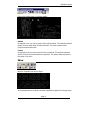
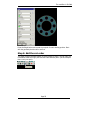
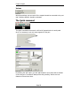
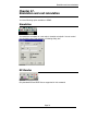
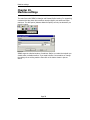
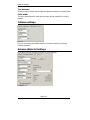
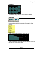
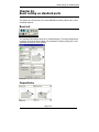
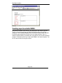
Step 1: Install the IGEMS-software
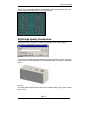
Extract all files in the installation if downloaded from our website or insert the
IGEMS CD-disk if available. Run the Install.exe file.
Picture 1
Install the IGEMS Software and follow the information on the screen.
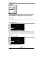
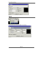
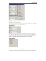
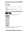
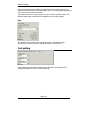
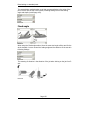
Step 2: Install Hardware lock driver
If you don’t have a Dongle (Hardware lock) or if you already have installed the
driver, then go to next step. Before you start the driver installation, remove any
USB-dongle from the computer. Follow the instructions on the screen. Insert the
USB dongle after installation of driver is completed.
Page 7
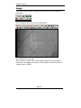
Installation
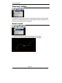
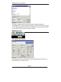
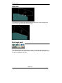
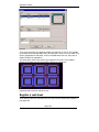
Picture 2
If everything is OK you should have a message like above image.
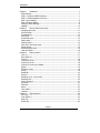
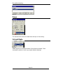
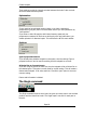
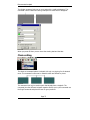
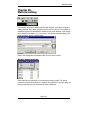
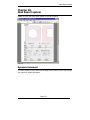
Step 3: Start IGEMS
Trial version
The only difference between the trial and the industrial version of IGEMS is that it
is not possible to save anything in the trial version. If you do not have any
password then IGEMS automatically will be running in trial mode.
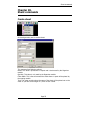
Trial or industrial version
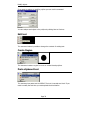
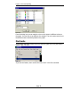
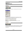
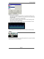
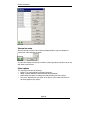
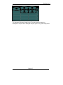
Picture 3
Start the password command.
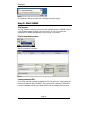
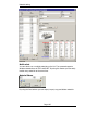
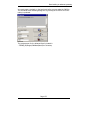
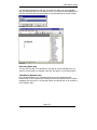
Picture 4
Load a password file.
If you have received a permanent password file, then press the “Load passwords”
button and select the file ( xxx.PWD). The password file is based on information
from the Hardware lock ID or the Hard Disk ID and the modules that you have.
Page 8
Installation
Trial code
If you want to test IGEMS for a limited time you will need a temporary code. Send
the Trial code to IGEMS Software AB and a temporary code will be returned to
you. Activate the password file by pressing “Extend trial time” and enter the code.
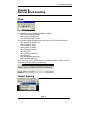
Step 4: Restart IGEMS
Restart IGEMS to complete the installation.
Floating License Manager
Floating license is an extra option to IGEMS that makes it possible to handle all
licenses from one computer used as server. Example: If you have one license of
IGEMS and you have installed IGEMS on several computers then it’s possible to run
IGEMS from any computer, but only on one computer at a time.
Step 1: (On server)
Install IGEMS floating license in a computer that are connected to a network. You
do not have to install the IGEMS Software.
Step 2:
Install the Hardware lock.
Step 3:
Start the Floating License Manager.
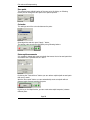
Write down the IP and the Port number of the server. Finally activate the toggle
Auto start.
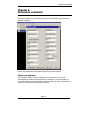
Step 4:
Load your password file for the Floating License Manager. (It’s a button where this
command can be started).
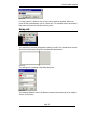
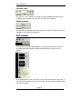
Step 5: (On clients)
Repeat the following procedure on all computers that should be connected:
1. Install IGEMS Software.
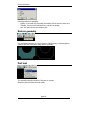
2. Start the Password program. Enter the IP and the Port number
Picture 5
Page 9
Installation
Updates
To be sure that you have the very latest version, please check for a new versions.
This can be done from our service center. You need to be connected with Internet
for using this service.
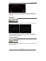
Picture 6
When you update just follow the instructions on the screen. Always install minor
updates in same directory as the previous version. No information changed by the
user is overwritten when making an minor update. If you install a new release (R6,
R7, R8) then use a new folder. The old version is not uninstalled, you can run the
old and new Releases at the same time.
Page 10
General CAD functionality
Chapter 2.
General CAD functionality
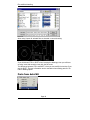
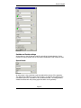
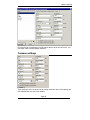
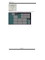
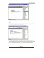
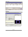
Language and units
Picture 7
From this command you can make the general settings for the CAD/CAM system
like Language and Units. IGEMS currently support 12 different languages: Czech,
Dutch, English, Finnish, French, German, Greek, Italian, Polish, Russian, Spanish
and Swedish.
Picture 8
The file locking can be activated and it handle only the IGEMS drawing files (ACD).
Zoom and Pan
You need a wheel mouse to work properly with IGEMS.
• Zoom: You will zoom in and out by rotating the mouse wheel.
• Pan: Press and hold the mouse wheel down to pan.
• Zoom extents: If you double click with the mouse wheel, then IGEMS will zoom
up the drawing in full screen.
If the mouse wheel is not working in this way then check the mouse settings in the
control panel. The mouse wheel button should be configured as Mid button.
Page 11
General CAD functionality
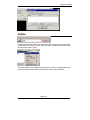
Command line
There is no command line in IGEMS but sometimes the program asks for additional
information. Be sure to always read the information at the line.
Picture 9
When something is inside brackets [Example] then this is the default value. This
can be accepted by using the Space or the Enter keys.
Short keys
By holding the mouse pointer over a command, you can see the short key for this
command.
Picture 10
If you want to repeat the same command, the space or Enter keys can be used as
a short key for last used command.
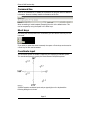
Coordinate input
The coordinate system in IGEMS is supporting the Cartesian coordinate system.
This coordinate system is used by the most common CAD/CAM-systems.
Picture 11
If IGEMS expects coordinate input and you type digits on the keyboard the
following dialog box is shown.
Page 12
General CAD functionality
Picture 12
Absolute coordinates
Always refer to IGEMS fixed zero point. It is typed X,Y as in following example:
110.5, 220.18
Relative coordinates
This always refers to the last used point, so it is rather a distance then a
coordinate. It is typed @X, Y as in following example:
@110, 218.9
Absolute polar coordinate
Always refer to IGEMS fixed zero point. It is typed DIST>ANGLE as in following
example:
150<45
Relative polar coordinate
Always refer to the last used point. It is typed @DIST>ANGLE as in following
example:
@180<225
Direction coordinate
This is the fastest way of enter coordinates. This is used if you just type one value
@DIST or DIST. This method takes the pointing direction and it is often used
together with Ortho mode. Example:
@200 or 200.
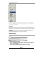
Object snap
If you have a command active that need coordinates input, then you can click on
the right mouse button. This will show you the list of object snaps that can be
used in IGEMS.
Page 13
General CAD functionality
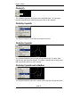
Picture 13
The different options finds coordinates on the drawing. It is also possible to use
short key for object snap. This is done by typing E, M, C, N, P, Q or T instead of
using the right mouse button.
Point filter
By using the point filter option (short key X) you can extract individual X and Y
coordinates from different points on the drawing to create a new composite point.
Snap from
The Snap from option asks for a point that will be used as the last point. This
option should be used together with relative coordinates.
Distance input
Several commands in IGEMS ask for a distance value.
Example:
Picture 14
In
•
•
•
this example you have 3 choices.
You can accept the value inside brackets [12.0000] by using the space key.
You can enter a new value.
You can pick two points by measuring a distance on the screen.
Page 14
General CAD functionality
Grid, Ortho and Snap mode
These modes can be activated or deactivated from following buttons or with the
short keys F7, F8 and F9.
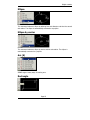
Picture 15
Grid mode
This mode shows a grid on the screen. The size and distance between the grid
points can be modified from the grid settings command.
Picture 16
Ortho mode
Sometimes it helps a lot having the possibility to pick points that are located in
vertical or horizontal direction. This can be done by activating the Ortho mode.
Snap mode
Whit this mode activated, the cursor will only snap to the grid points.
Select objects
Many commands need objects as input. For example: Erase, Move, Copy and
others. The select object function IGEMS works as follows:
Select
•
•
•
Select by picking: Pick on an object.
Select by window: Needs two points. Click where there is no object, next point
must be to the right side. The objects must be completely inside the window to
be selected.
Select by crossing: Needs two points. Click where there is no object, next point
must be to the left side. It is enough if just a small part of the object is inside
the window to be selected.
Deselect
This is done in the same way as Select except from that the SHIFT key must be
activated at the same time.
You can mix select and deselect, when your selection is done then press space.
Page 15
General CAD functionality
Automatic base point
Many commands has an automatic base point selection:
Specify base point [auto]
You have then two choice. You can pick a point as base point or you can except
the auto option by pressing space or enter. The new option take the center of the
extends of all selected objects.
Undo and Redo
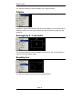
Picture 17
IGEMS has an Undo and Redo system that make it possible to Undo and Redo up
to 10 steps backward.
Page 16
Object creation
Chapter 3.
Object creation
Line (L)
Picture 18
This command asks for a start point and then next point. The command must be
interrupted by space, enter or escape. Backspace can be used for undo the last
line segment there is also a special Polar option (Short Key A).
Picture 19
With this option you can enter a relative angle and a distance.
Point (Shift P)
Picture 20
Ask for input of point positions. The point command must be interrupted by space
or escape.
Picture 21
This visual presentation of the point can be modified from the Point style command
on the Format menu.
Page 17
Object creation
Circle (C)
Picture 22
This command requires a center point and a radius/diameter. You can toggle
between radius/diameter modes by using the D key on the keyboard.
Circle by 2 points
Picture 23
This command makes a Circle that goes through two points.
Circle by 3 points
Picture 24
This command makes a circle that goes through three points. It is often used
together with the snap mode tangent. This makes it possible to find center points
that are difficult to define by other methods.
Circle by 2 points and a Radius
Picture 25
This command makes a circle with a specific radius that goes through two points.
Page 18
Object creation
Ellipse
Picture 26
This command makes an ellipse by defining first axis diameter and then the second
axis radius. The ellipse is automatically converted to a polyline.
Ellipse by center
Picture 27
This command makes an ellipse by center and two axis radius. The ellipse is
automatically converted to a polyline.
Arc (A)
Picture 28
IGEMS support many ways of creating arcs.
Rectangle
Picture 29
Page 19
Object creation
This command makes a polyline rectangle from 2 opposite points.
Polyline
Picture 30
A polyline is chain of lines and arcs that are joined together into one object. When
drawing a polyline you can toggle between line and arc mode by typing A on the
keyboard.
Rectangle by X, Y and center
Picture 31
This command makes a polyline rectangle by asking for X-size, Y-size and then a
insertion point and rotation angle.
Bounding box
Picture 32
This command makes a rectangle around selected objects.
Page 20
Object creation
N-Gon (Polygon)
Picture 33
This command make a polygon by asking for number of sides, radius and rotation
angle. You can toggle for outside or inside radius type by typing O on the
keyboard.
Polyspline
Picture 34
This command makes a spline that goes through a set of points. When the
command is ended the spline is converted to a polyline.
Obround
Picture 35
This command makes an obround by asking for two points and a radius.
Page 21
Object creation
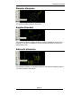
Swell
Picture 36
The Swell command makes a trimmed offset around a selected object. The
command asks for objects and a radius.
Text (Shift T)
Picture 37
Before you enter the text, the command asks for insertion point and text size. By
clicking right mouse button you can change rotation angle and size.
Picture 38
Centroid
Picture 39
This command inserts a point in the centroid of a closed object.
Page 22
Object position
Chapter 4.
Object position
The commands described in this chapter are using functions described in Chapter
2. (Select object, Coordinate input, Object snaps and so on).
Move (M)
Picture 40
This command asks for objects to move, then a base point and finally a new
position. The selected object will be moved to the new position.
Copy (Shift C)
Picture 41
This command will ask for objects to copy, then a base point and finally a new
position. The command must be interrupted by the ESC-key.
Scale (S)
Picture 42
This command asks for object to scale, then a base point and a scale factor. If you
click right mouse button instead of entering the scale factor you will have following
options.
Picture 43
Page 23
Object position
•
•
•
•
•
•
Reference by X length:
This option automatically calculates the scale factor. Enter the outermost size
in X.
Reference by Y length:
This option automatically calculates the scale factor. Enter the outermost size
in Y.
Stretch scale:
With this option you can enter different scale factors in X and Y.
Box scale:
This option allows you to enter different outermost size in X and Y. In this
option it is best to have the zero point at the lower Left corner of the selected
objects.
Reference:
Asks for a reference length, and then a new length. All objects will be scaled
by reference to this two length.
Value:
Enter a scale factor (2=double size, 0.5 will scale to half size).
Rotate (R)
Picture 44
This command rotates an object around a specified point. Instead of entering the
new rotation angle you can use the Reference option.
Picture 45
With this option you can make a relative rotation from a Reference angle and a
new angle. As standard the rotate command is in copy mode. It is possible to turn
if the copy mode from the environment settings (se Picture 8).
Mirror (Shift M)
Picture 46
This command asks for object and then a mirror line. The selected objects are still
selected after the mirroring, if you want to delete the original then use the Delete
key.
Page 24
Object position
Erase (E)
Picture 47
This command erases the selected objects from the drawing.
Polar Array
Picture 48
This command copies the selected objects in a polar array. Following dialog box is
shown. The settings in the dialog box are self explained.
Picture 49
Rectangular Array
Picture 50
Page 25
Object position
This command copies selected object in a Rectangular Array. Following dialog box
is shown.
Picture 51
The settings in the dialog box are self explained, but here are some remarks.
Delta X and Y
The default distance is the size of the selected object in X and Y. By clicking on
some of the buttons shown in the picture you can point out a distance on the
drawing.
Page 26
Modify objects
Chapter 5.
Modify objects
Offset (O)
Picture 52
This command makes an offset of the selected object to a specified distance. The
command asks for a distance, object and a side. If you hold down the CTRL or/and
SHIFT key when picking the side you can make a non trimmed offset or offset with
outside arcs.
Explode (X)
Picture 53
This command explodes a block or a polyline to separate objects. The opposite
command to Explode is Join.
Trim (T)
Picture 54
The Trim command deletes the portions of an object that intersects with other
objects.
Picture 55
You can now click on that portion of the object that you want to delete. If you hold
down the Shift key the trim function is inverted, the complete object except the
portion that you click on will then be deleted.
Page 27
Modify objects
Extend
Picture 56
The Extend command extends objects to it intersect with other boundary’s.
Picture 57
When selecting the bounding edges, you can select the objects to extend.
Lengthen
Picture 58
This command lengthen selected object.
Fillet (F)
Picture 59
This command makes a tangential arc between two objects. If the object is a
polyline and you hold down the CTRL-key then all corners will be selected.
Fillet zero
Picture 60
This command does the same as Fillet except that the radius is always set to 0.
Page 28
Modify objects
Chamfer
Picture 61
This command asks for two distances (A and B) and two objects. A chamfer line is
inserted between the two objects.
Join (J)
Picture 62
This command joins objects to a polyline. Only objects that has no gap or overlap
are joined together.
Picture 63
The result of the Join command can be found on the information line. The opposite
command to Join is Explode.
Extended Join
Picture 64
Extended join is similar to join but has also a variable tolerance. If there is a gap or
an overlap shorter then the tolerance then the command will make a line between
the objects.
Polyline editor
Picture 65
Page 29
Modify objects
If you want to analyze or modify a polyline you can use this command.
Picture 66
You can analyze each object in the polyline by clicking Next or Previous.
Edit text
Picture 67
This command makes it possible to change the contents of existing text.
Create Region
Picture 68
This command creates a region from one or several closed polylines.
Paste clipboard text
Picture 69
This command can paste text into IGEMS. The text is inserted as a block. If you
need to modify the text then you must explode the block before.
Page 30
Modify objects
Picture 70
Delete (Del)
Delete can only be used on selected objects when no other command is used.
Break
Picture 71
This command breaks up objects in several portions. The command asks for an
object and a break point.
Subtract
Picture 72
This command removes the area from a closed object by subtracting the area from
other closed objects.
Picture 73
The above image shows the result of the Subtract command.
Page 31
Modify objects
Union
Picture 74
The Union command creates a new closed object by union all selected closed
object.
Picture 75
Boundary trim
Picture 76
This command trims and erases all parts that are inside or outside a closed object.
Page 32
Dimension command
Chapter 6.
Dimension command
The general settings for all Dimension command are handled by the Dimension
Settings command.
Picture 77
Most of the settings are self explained but here are some remarks.
Object color and layer
It is possible to define a color for Dimension lines and text. This color will
automatically be used when using dimension command. You can also define a
Layer that always will be used for the dimension object. By using a special layer it
is easy to turn dimension information on and off.
Page 33
Dimension command
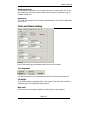
Auto scale
Picture 78
If you set the Auto Scale to a specific paper size, the Dimension scaling will be
automatically calculated. The calculations are done when you use the first
dimension command. If you press the button shown in previous picture the
dimension scaling will be recalculated.
Value scaling
By using the new variable “Value scaling” you can force IGEMS to suggest a scaled
value of the dimension text.
Linear dimension
Picture 79
This command makes Horizontal, Vertical or Aligned dimensions. If you want to
measure an existing object, you can just pick on that object. If you for example
want to measure the distance between two objects, then press space and enter
two points.
Radius dimension
Picture 80
This command makes Radius dimensions.
Page 34
Dimension command
Diameter dimension
Picture 81
This command makes Diameter dimensions.
Angular dimension
Picture 82
This command makes an Angular dimension from the information of two lines or
polylines. If you have no object you can press space and define the vectors by
picking three points
Automatic dimension
Picture 83
This command makes a non standard dimension information by adding position in
X,Y and the radius of the objects.
Page 35
Various commands
Chapter 7.
Various commands
Distance
Picture 84
This command asks for two points and present information at the information line.
Picture 85
Info (I)
Picture 86
This command shows information about selected objects.
Picture 87
Parametric parts
Picture 88
Page 36
Various commands
With this command you can create parametric geometries. It is possible to make
new parametric parts templates. Contact IGEMS if you need more information on
how to make your own shapes.
Picture 89
Click on a symbol
Picture 90
The geometry can be inserted as a block or as separate objects. It is also possible
to insert the geometry with an optional rotation angle.
Page 37
Various commands
Shape library
If you are frequently inserting the same shape of geometry it is now possible to
store the shape in the Shape library.
Add shapes to the library
This is the workflow to add new shapes:
Step 1:
Create the geometry.
The position of the geometry is important since the absolute 0,0 will become the
base point for the shape. In this example we have moved the geometry so
absolute 0,0 is at point A-
Picture 91
Step 2:
Start the Parametric part command
Picture 92
Press the Parametric part button
Picture 93
Press the Add button and enter a name for the new shape.
Page 38
Various commands
Picture 94
Finally select the geometry.
Select objects (Select the geometries)
The Shape is now stored in the library and can be reused at any time.
Picture 95
Insert shapes from the library
Start the Parametric parts command. Select the shape you want to insert.
Picture 96
If you want to insert only one shape, then use the Singe button. If you want to
insert multiple shapes then use the Multi button. From this window you can also
control if you want to modify the angle of the inserted shape or if the shape should
be represented as a block.
Page 39
Layers, colors and plotting
Chapter 8.
Layers, colors and plotting
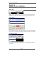
Layer (Y)
Picture 97
IGEMS supports unlimited number of layers. If you should create DXF-files that
should be used in other CAD systems, be sure not tu use space in layer names.
Layer options
Picture 98
From this dialog box you can create new layers, delete layers and change default
color of a layer. If you delete a layer then all objects on that layer will be deleted.
Change active layer
Picture 99
You can change active layer from the layer list. All new objects will be placed in
the new layer.
Page 40
Layers, colors and plotting
Color
Picture 100
You can change color by selecting any color from the list. Setting the color to “By
Layer”, means that the active color will be the color defined in the layer setting.
Picture 101
If you want to use other colors than you have in the list then press the Draw color
button.
Plot (Ctrl+P)
Picture 102
The plot command will open following dialog box.
Picture 103
The buttons can be used for handling different plot styles.
Page 41
Layers, colors and plotting
Picture 104
From this dialog box you can map the colors on the screen to different colors on
the paper. You can also set up different line weights. The color mode controls how
the different colors should be plotted on the paper.
Plot limits
If you always use same plotting area over and over again then it’s a good idea to
specify a plot limit area.
Picture 105
If you use this feature, then use the Plot area “Limit” in the Plot command.
Page 42
File and Block handling
Chapter 9.
File and Block handling
Open
Picture 106
Following files can be opened as standard in IGEMS:
• ACD (Files created by IGEMS),
• DWG (AutoCAD drawing file).
• DXF (Draing Exhange Format)
If you have the Data Exchange option then you can also open following files:
• CBF (Created by CAMbAL cut)
• GEO (Created by Tops)
• TAG (Created by Taglio)
• ORD (Created ny Omax)
• MEC (Created by Lantek)
• IGS (IGES files)
• PRT (Created by Admicut)
• PS (Postscript)
• EPS (Encapsulated postscript)
• WMF (Windows Meta File)
When you open a file, it will be opened in a separate drawing window. You can
have many drawings open at the same time.
Picture 107
Import drawing
Picture 108
Page 43
File and Block handling
Picture 109
When using Import all selected files are inserted in current drawing.
Picture 110
If you hold down CTRL or SHIFT when inserting the drawings, then you will have
an extra insert that contains a text with the file name.
The difference between CTRL and SHIFT is that you can modify the text size if you
use the SHIFT. The text information can be used later when making parts for 2DCAM or Nesting Option.
Paste from AutoCAD
Picture 111
Page 44
File and Block handling
If you want to Copy/Paste from AutoCAD then you can use this function to paste
the drawing into IGEMS.
Save
Picture 112
This command saves the entire drawing. The default format for IGEMS is ACD and
all information saved in this format can be reused by IGEMS. The DXF-format
should only be used for communication with other software.
Export
Picture 113
This command asks for objects to be saved. The information can be saved as an
ACD or DXF-file.
Block
Picture 114
The block description is saved in current drawing instead of a file. If you need a
set of block, it is a good idea to make the blocks and then save the drawing as a
template. The Block command shows following dialog box.
Page 45
File and Block handling
Picture 115
Insert
Picture 116
The command shows all blocks available in the drawing.
Picture 117
Page 46
File and Block handling
Save as template
Picture 118
A template is a drawing that will be used every time you create a new drawing. If
you should make a template do as follows:
• Start a new drawing
• Define layers and colors.
• Define blocks.
• Draw objects.
• Save as template, and enter a name for the template.
Picture 119
Select a template
Picture 120
Select a template and press “Set default” button.
Page 47
File and Block handling
Picture 121
Purge
Picture 122
This command will remove all unused block and layer on the drawing.
Cut and Paste
Picture 123
IGEMS Supports the standard Windows Cut and Paste commands. These
commands is perfect to use for copy objects between drawings.
Page 48
SignMaker option
Chapter 10.
SignMaker option
Font tracer
Picture 124
The Font tracer command can import TrueType fonts and convert the information
into CAD-geometry.
Picture 125
If you want to add more fonts, you can add fonts to the standard windows font
directory or to the …”IGEMS_R8/Plugins/Signmaker/FonTracer/Fonts” directory.
Page 49
SignMaker option
Picture 126
The result is a polyline with lines and arcs.
Image Tracer
Picture 127
This command converts bitmap files to CAD vectors.
Picture 128
The command has several options that can be used for optimizing of the result.
Page 50
SignMaker option
Picture 129
Click on the button shown in previous picture.
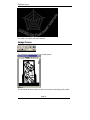
Picture 130
Outline
In example A you, can see the result of the outline method. This method should be
used if you have solids areas of black and white. This option creates closed
polylines around black areas.
Curves
In example B you can se the result of the curve method. This method should be
used if you have lines that describe the geometry. This option makes a polyline in
the center of the lines.
Skew
Picture 131
With this command you can tilt object.
Picture 132
In the example above the Skew command is applied on objects from Image tracer.
Page 51
SignMaker option
Image
The Image command makes it possible to insert and use a bit map image as a
background.
Picture 133
The command starts by clicking on the Image button.
Picture 134
JPG and BMP files can be used.
After insertion it’s a good idea to use the Scale command to get the image in
correct size. The Image can be copied, scaled, rotated or mirrored like all other
drawing objects in IGEMS.
Page 52
CAM-Tools option
Chapter 11.
CAM-Tools option
Clean Up
Picture 135
This command removes double objects, overlapping geometry and joins gaps in
the geometry.
Picture 136
All objects that should be cleaned must be lines, arcs and circles. If you have
polylines then you can click the explode button. The Delete buttons is not very
often used. The Clean button executes the command.
Picture 137
On the information line you can se the result of the Clean up command.
Curve fit
Picture 138
All objects that should be used by this command must be polylines. This command
optimizes the polyline. Short line segment will be converted to longer lines or arcs.
The command asks for a tolerance, the result of Curve fit can be found on the
information line.
Page 53
CAM-Tools option
Picture 139
Vectorize
Picture 140
This command works the opposite as the Curve Fit command. It converts all arcs
to short linear vectors. If you need this feature you must add this button to a
toolbar.
Replace
Picture 141
This command asks for a replacement object, then object to replace. The selected
object will be replaced by the replacement object.
Picture 142
A is before and B is after the command. The R object is the replacement object
and the rectangles are the object to replace.
Edge fix
Picture 143
Edge fix can replace a portion of a polyline with an arc or a line.
Page 54
CAM-Tools option
Picture 144
Edgefix ask for a start point (A) and an end point (B). The portion between the
points will be replaced by an arc if you pick a point or with a line if you press the
space button.
Poly joint
Picture 145
This command joins two closed polylines to one, or divide one closed polyline into
two.
Picture 146
If you click on two points that are outside the closed object (A and B) then the
object will be divided. If you pick two points that are inside closed objects (C and
D) then the objects will be joined.
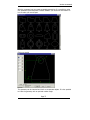
Contour analyzer
Picture 147
This command makes red circles on gaps between objects and yellow circles if the
objects are overlapped.
Page 55
CAM-Tools option
Picture 148
Boundary polygon
Picture 149
This command can create closed polylines from enclosed areas.
Picture 150
Click inside where you want the new polyline, press space to move the polyline,
press space again to end the command.
Page 56
The workflow in 2D-CAM
Chapter 12.
The workflow in 2D-CAM
The workflow for creating a CNC-file in IGEMS can be described in 5 steps.
Step 1: Create the geometry
A part must be created from existing geometry. This geometry can be created in 3
different ways.
1. It can be drawn using the different CAD-command in IGEMS
2. It can be imported from other CAD systems.
3. It can be automatically created from our parametric parts library.
The geometry that describes the outside and inside contour must be free from
gaps and overlapping objects.
Step 2: Create a part
Picture 151
Picture 152
By clicking on the button “Contours” you can select the objects describing the
boundary geometry. By clicking on “Other objects” you can select objects that
should be used for other purposes like marking for example.
Page 57
The workflow in 2D-CAM
Non geometrical information
Picture 153
This information can be used by the Organizer module. It can also be printed on
reports.
1. Name: Is used for identification of the part. The letter “#” can be used as a
count up number.
2. Quantity: Number of parts that should be produced.
3. Date: The date can be printed out on reports.
4. Customer.
Geometry optimization
Picture 154
We recommend that you always use the geometry optimization. The value of the
geometry optimization must always be larger than the maximum tool radius
compensation that should be used in the machine.
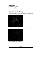
Step 3: Add toolpath
There are different commands to apply a toolpath. One of them is the Single
command.
Picture 155
Page 58
The workflow in 2D-CAM
Picture 156
Press the Single button and create the toolpath for each starting position. Start
with the geometry that should be cut first.
Step 4: Add the cut-order
The Sheet prepare command makes an object called Cut order. The cut order has
information about the origin point and the order between parts. (On this example
there is only one part).
Picture 157
Page 59
The workflow in 2D-CAM
Picture 158
Set the zero point
You can set the “Zero point” to an optional position on a part.
Picture 159
Page 60
The workflow in 2D-CAM
Other options in this command will be described later in this manual.
It’s also possible to go direct to Step 5. In that case the step 5 will use the default
values from Sheet prepare.
Step 5: Postprocessing
Last step is to create the CNC-file.
Picture 160
If you are using IGEMS tool radius compensation, then the command ask for a tool
diameter.
Picture 161
If you have not made Step 4 (Sheet prepare), then the command will ask for parts
to post process.
Picture 162
The Post processing is executed by clicking on the button start. The result will be a
CNC-file and a report file. These files can be viewed by clicking on the Report or
the View NC-file.
Page 61
Create toolpath
Chapter 13.
Create toolpath
There are different commands that can create toolpaths. The commands has a
different level of automation.
The Auto command
Picture 163
This command automatically creates a toolpath for one ore several parts at the
same time. This command is perfect to use on parts that have been nested without
any toolpath on them.
Picture 164
Page 62
Create toolpath
Picture 165
Outside and Inside settings
All the values on the left side are used for controlling the leadin/out, piercing type,
cutting quality and the tool radius compensation.
Special leads
Picture 166
In many cases it is a good idea to put the leads at the corners of the geometry.
This lead can be defined as corner lead. If there is no place for the lead then the
command will test if it is possible to use an alternative lead. This lead geometry
should be defined with the piercing type that starts on the geometry.
Leads position
Picture 167
Page 63
Create toolpath
These settings control the internal cut order between the holes. It also controls
where the leads should be placed.
Optimization
Picture 168
If your machine has unlimited memory space or you have a sequential
postprocessor (long file) then it will be a better result if you use optimization by
“Lead position”.
If you have an older NC-machine with limited memory space and your
postprocessor creates a NC-file that are built up by main and subroutines, you
should optimize it for identical copies. This will make the NC-file much smaller.
Settings
Picture 169
Ignore prepared contours
If you already have added a toolpath on some parts, then the settings “Ignore
prepared contours” can be used for avoiding that the toolpath are re-done.
All holes first or Connect to part
If you are using the option All holes first, then the toolpath will do all holes first on
the selected parts. This option is mostly used for oxyfuel cutting. This will create a
disconnected toolpath. In all other cases the “Connect to part” option is the most
common setting.
Picture and information is deleted
The Single command
Picture 170
The Single command requires more input, but gives you more control over the lead
positions and the internal cut order. The single require one click for each part on
the part.
Page 64
Create toolpath
Picture 171
Outside and Inside settings
All the values on the left side are used for controlling the lead selection. It also
controls the cutting quality and the tool radius compensation that should be used.
Special leads
Picture 172
In many cases it is a good idea to put the leads at the corners of the geometry.
This lead can be defined as corner lead. If there is no place for the lead then the
command will test if it is possible to use an alternative lead. This lead geometry
should be defined with the piercing type that starts on the geometry.
Page 65
Create toolpath
Various
Picture 173
With these settings you can control if the toolpath should be connected to the part
and if collision detection should be activated.
The Quick command
Picture 174
The Quick command can be used on all kind of geometries but is mostly used
when it is necessary to cut only some segments of the part.
Picture 175
Picture 176
By selecting the “Slit” option, you can add toolpath to open parts that are located
on the solid part. The lead will always follow the geometry, and the over cut
distance will be cut two times.
Page 66
Create toolpath
Picture 177
By selecting the “Contour” option, you can add toolpath to the inside and outside
geometry.
Lead angle
This option can be used only together with the contour option. When activated the
command also asks for the lead in and lead out angels.
Manual
Picture 178
This is the most flexible command for creating a toolpath, but it is also the
command that require more input from the user.
Picture 179
By using this function you can create a toolpath step by step. All movements in the
machine will be in the same order as you enter the sub-commands.
Following sub-commands are available:
Page 67
Create toolpath
1.
2.
3.
4.
5.
6.
7.
8.
9.
10.
11.
Rapid:
Turns the cutting off and add a rapid transport.
Start:
Start the cutting process.
Line:
The cutting will continuo linear to a selected point.
Next:
The cutting will proceed to next object.
Follow to: The cutting will proceed all the way to it reach selected position.
Quality: The cutting quality can be changed between different objects.
Event:
It is possible to add different event that can control the
Postprocessing process. The postprocessor must be adapted for this function.
Undo:
Undo the previous command.
Loops:
Can activate or deactivate corner loops.
Done:
Finish the manual command.
Cancel: Do not save the manual toolpath.
The command line
A good idea is to look at the command line. In many cases you can use the
defaults. The defaults input are inside brackets [example] and are activated by the
space bar on the keyboard.
Marking
Picture 180
The marking command activates functions on the machine that mark the surface of
the material. In a Waterjet machine it is possible to use pure water without
abrasive for marking materials.
Picture 181
If you have markings that should be connected to a part, then the marking object
must be selected with the “Other object” button in the Create part command.
Page 68
Create toolpath
Picture 182
The marking command can be used on all normal objects as polylines, arcs, and
lines. But it can also be used for points and texts objects.
Attribute
The attribute is optional text information that can be used for machines with more
than one marking method. The attribute will then inform the postprocessor about
equipment to be used.
Multi or Singe
If you select the Multi button, then you can select multiple objects at the same
time. If you select the Single button then you must click on each object. The start
point is at that endpoint closest to you click point.
Page 69
Disconnected toolpath
Chapter 14.
Disconnected toolpath
A toolpath that is connected to the part are very simple to handle. If you move a
part then you also move the toolpath or opposite. But sometimes it is necessary to
create toolpath that are disconnected from parts. Following commands creates
disconnected toolpaths.
Common cut line
Picture 183
Depending on the geometry of the parts you can sometimes save a lot of
machining time by using common cut line.
Picture 184
The common cut line can be started by clicking on this button.
Picture 185
Page 70
Disconnected toolpath
This dialog box shows the option “Sheetwise”. This method is cutting in as long
straight lines as possible. The Part distance must be the same as the diameter of
the jet. If not, the parts will have incorrect dimensions or may not be machined.
Picture 186
The option “Partwise” is completing each part before starting to cut next part.
Picture 187
The option “Create lines” creates only drawing objects. These objects can be used
with the quick or manual command for creating the toolpath.
Bridge
Picture 188
Page 71
Disconnected toolpath
The Bridges command joins two or more parts with a small tab between. This
command is often used when cutting small parts to avoid them to disappear.
Picture 189
Picture 190
When you press OK then you can insert the starting lead and the tabs.
Chain cutting
Picture 191
The chain cut command makes a toolpath with only one piercing for all selected
parts. This command is often use in materials which are difficult to pierce.
Picture 192
This command can only be used on parts that already have a toolpath. The
command joins the different toolpaths together. Before you try this command use
the Single command and place the lead on good positions.
Page 72
Disconnected toolpath
Picture 193
For saving time it is better to use as high cutting speed as possible. When you
press OK the command asks you for a fence line. The toolpath will be connected in
that order the fence line intersect with the parts.
Scrap cut
Picture 194
This command is specially designed for making cut offs. The command can control
where the height sensor should be activated and deactivated.
Picture 195
The settings are controlled in following dialog box.
Picture 196
The measure distance control the distance between the measuring points (height
sensor on/off points).
Page 73
Various command
Chapter 15.
Various command
The Hole command
Picture 197
This command can be used for various things. The result from using this command
is controlled by the postprocessor.
Picture 198
Some example:
1. Can be used for cutting small holes.
2. For controlling drilling units.
3. For controlling multi operation macros like drilling and the tapping.
4. Can execute machine macros defined by the machine.
Picture 199
The command first asks for a filter object. By using the filter, you can easily select
circles with a specific radius or a block with a specific attribute.
The command then takes following information to the postprocessor:
1. X and Y position of block, circles and points.
2. The attribute.
3. The radius if you select a circle.
4. The angle of the block.
Page 74
Various command
Again! This is a command made for customization, what should happen when you
use this command is depending on the postprocessor.
Picture 200
HQCH High Quality Circular Hole
The feature HQCH is a feature to make High Quality Circular Holes (HQCH)
This option is activated by the Hole command.
Picture 201
The name of the fixed attribute is HQCH. By using this attribute you can cut small
circular holes with very high quality. Valid diameter starts at 1.2*Max tool diameter
and up.
Picture 202
The HQCH feature takes longer time than the standard cutting, but it gives a much
better result.
Page 75
Various command
Disconnect toolpath
Picture 203
This command can be used to convert a connected toolpath into a disconnected
toolpath. The command asks for one ore several parts that have a toolpath. The
result will be separated parts and toolpaths.
Break toolpath
Picture 204
This command breaks up a disconnected toolpath into two parts.
By clicking on the rapid transport (A) the toolpath will be divided.
Picture 205
Page 76
Various command
Connect toolpath
Picture 206
This command connects an optional toolpath to a part.
Select the part, then the toolpath.
Join Parts
Picture 207
With this command you can join several parts to one part.
Select first the main part, then the other parts to join. The name quantity, date
and customer information will be taken from the main part. This command can
create a part from several external geometries.
Split part
Picture 208
This command can only be used on joined parts.
If the part has a toolpath then the toolpath will be removed before the parts are
split.
Page 77
Various command
Lead settings
Picture 209
Picture 210
The lead settings command can also be activated in the Single and Auto command
by clicking on one of the rectangular buttons.
Picture 211
Overcut
The geometry of the leads can be adjusted by changing the values shown in last
picture. The overcut value can also be negative.
Page 78
Various command
Linear piercing value
Picture 212
When using piercing type 0 it’s possible to use the Linear piercing distance from
the material database as a over cut value.
Piercing
Picture 213
The different piercing is following:
o On geometry, means that the start of cutting will be activated after the lead in.
This will result in an invisible lead. This means that the lead it self does not
have to be collision detected. This piercing is perfect to use on small holes or
when other leads do not fit.
o Direct piercing, do not use any delay, the piercing will be linear during the
lead.
o Stationary piercing is not often used. The time for the piercing is controlled by
each material.
o Circular piercing, means that the jet will make circular movements during the
piercing. The piercing diameter and number laps is controlled by each material.
o Stationary low is not often used. The method makes a pre-piercing of all holes
on the sheet, before start cutting.
o Circular piercing in low pressure, is pre-pierceing all holes before start cutting.
The piercing diameter and number of laps is controlled by each material.
Save and delete
Picture 214
These buttons are used for saving and deleting leads from the lead library.
Page 79
Various command
Connect lead and material
Picture 215
If you activate these toggles, this lead will always become standard for the active
material. This is an important function if you must have a special designed lead for
a special material.
Picture 216
Insert, Replace and Delete
These buttons can not be activated if you have started the lead library from Auto
or Single. By using this command you can Insert, Replace or delete leads on the
part of the drawing.
Picture 217
Cutting Quality
Picture 218
On most command it is possible to set the cutting quality while creating the
toolpath. By using the Quality command you can also set the quality afterwards.
Press the Quality button and select the part you want to change.
Page 80
Various command
Picture 219
Following options are available:
o Paint, makes it possible to change portions of a geometry by clicking on two
points and a side. If you double click on the geometry the entire geometry get
the same quality.
o On part, the entire part gets the selected quality.
o Fence, makes it possible to make a fence around an area. Everything inside
that area will have the selected quality.
o Other parts, makes it possible to select other part on the drawing. The part
you select will get the selected quality.
Picture 220
In the example above everything inside the fence will have the selected quality.
Clone
Picture 221
By using the Clone command you can transfer properties from one part to another.
Select the part with correct information.
Page 81
Various command
Picture 222
Following options are available:
o Quality, in this case only the quality information will be cloned to other part.
o Toolpath, this clones the lead positions, and also the quality.
o Part, this option clones the complete part.
Restore geometry
Picture 223
It is sometimes necessary to convert a part to CAD-geometry. Following picture
shows a part before and after using Restore geometry.
Picture 224
Part text
Picture 225
This command display the name of the part on the part.
Select the parts and enter the text height.
Page 82
Various command
Picture 226
If you set the text height to zero, then you can remove the text.
Part distance
Picture 227
This command shows the closest distance between two parts. Start the command
and select two parts. The distance is shown on the information line.
Contour smoothing
Picture 228
This command was developed for laser cutting in thick material. The command
creates fillet radius in all corners on a closed polyline.
If you hold down the Shift key, all corners will be rounded except the closest.
Page 83
Various command
Picture 229
Tool setup
Picture 230
Many machines are equipped with more than one cutting tool. The tool settings
can be controlled with the tool setup command.
The command shows following dialog box.
Picture 231
Set active tools
By activating different tools 1-8 and then press the Apply button and select parts,
you can make master and slave parts. The distance between all tools will be the
tool distance value.
Page 84
Various command
Picture 232
The master and the slave parts have different colors.
Minimal distance
By using this option the tool distance will be calculated automatically.
Picture 233
Equal distance
This option asks for a sheet. The sheet will be divided in as many areas as you
have active tools.
Edit part
Picture 234
With the Edit part command you can change parameters related to the toolpath of
the part.
Page 85
Various command
Picture 235
Internal cut order
With the Manual, Closest, Left to Right and Spread option you can change the
internal cut order between the parts.
Picture 236
You can also change the internal cut order by select geometry and then use the up
and down arrow buttons.
Other options
This command can also do following:
• Delete: This option delete the selected geometry.
• Rapid: Creates additional rapids between two geometries.
• Lead: Makes it possible to change the lead geometry and the piercing.
• Zero point: Normally the zero point of the part is to the lower left corner. It
can be changed by this option.
Page 86
Cut order and Postprocessing
Chapter 16.
Cut order and Postprocessing
Sheet prepare (Cut order)
Picture 237
You must have a toolpath before you can use this command. Select all parts that
should be included in the cut order. Following dialog box is shown:
Picture 238
By clicking on following pictures you can remove or add parts that should be
included in the cut order.
Picture 239
Page 87
Cut order and Postprocessing
Zero point
The program has a default location of the zero point. By clicking on following
button you can change the zero point to an optional position.
Picture 240
Cut order
This settings control the cut order between the parts.
Picture 241
Select algorithm and then press “Apply..” button.
The cutting order can also be changed by using following buttons.
Picture 242
Extra rapid movements
It is possible to detect and create a toolpath that moves the tool around parts that
are smaller than a specified size in X and Y.
Picture 243
By clicking the “Find collisions” button you can make a rapid toolpath around parts
that are too small.
With the “Box rapids” button you can automatically create a toolpath without
diagonal rapid transport between the parts.
Picture 244
By clicking on the Rapid button, you can create extra rapid transports, between
different parts.
Page 88
Cut order and Postprocessing
Final point
It is sometimes important to make a final transport of the jet. This can be done by
clicking on following button.
Picture 245
Enumerate
This function inserts number on all parts. The number sequence is the same as the
cutting order.
Picture 246
Stop
By clicking on following button you can add a stop before the part is cut.
Picture 247
Postprocessing
The command is started by clicking on following button. If you don’t have a cut
order, then the command ask for parts to cut and then create cut order.
Picture 248
If you have more than one cut order you must select which cut order that should
be used. In the CAM-Settings described on page 111 you can activate an
automatic interference check before the posting is started.
Page 89
Cut order and Postprocessing
Picture 249
You can start post processing, view CNC-file or report file by clicking on the
buttons on the right side of the dialog box.
Picture 250
Other settings
If you temporary want to change machine or material, you can click on the change
button. If you have a very long CNC-file, then the post processing will go faster if
you activate the Silent console.
Page 90
Simulation and cost calculation
Chapter 17.
Simulation and cost calculation
You have following option available in IGEMS.
Simulation
Picture 251
You must have a toolpath or a cut order to simulate a toolpath. You can control
the simulation speed and positions in following dialog box.
Picture 252
NC-Reader
Picture 253
Only standard ISO and ESSI files are supported in this command.
Page 91
Simulation and cost calculation
Picture 254
If you get a strange result, then you may need to change the settings of
“Incremental arcs”. You can change the zero point. You have an option if you want
to view rapid transport and you can also use Step mode. If you use the step mode
you can step forward by clicking on space or escape.
Estimate cost
Picture 255
Select parts for cost calculation.
Picture 256
In this dialog box you can find the cost for the selected parts. By clicking on the
report button you can make a report.
Page 92
Sheet commands
Chapter 18.
Sheet commands
Create sheet
Picture 257
All closed geometry can be used as sheet.
Picture 258
This command has following options:
Name: This value is printed out on reports and it is also used by the Organizer
module.
Quantity: This value is only used by the Organizer module.
Collar width: This is the area around the sheet where no parts will be placed by
the nesting module.
Text: This value controls where the name of the sheet will be printed out on the
sheet. If you have a text height of 0, then no text is used.
Page 93
Sheet commands
Predefine sizes
Picture 259
By using the + and – button you can add or remove predefined sheet sizes. By
pressing the Insert button you can insert the sheet on the drawing.
Define geometry
Picture 260
You can define the geometry when you start the command. You can also define a
rectangle or use a polyline as geometry.
Part browser
Picture 261
All parts have a property called Quantity. By using the part browser you can se
how many parts that have been placed and the quantity of all parts on the
drawing.
Picture 262
In the picture above, 4 out of 10 and 5 out of 10 has been placed on the sheet. If
you hold down the right mouse button on a part you can se more information that
is stored on the part.
Page 94
Sheet commands
Lock sheet
Picture 263
When you lock the sheet, all parts are converted to holes on the sheet. On the
picture below you can see the result of locked sheet.
Picture 264
Unlock sheet
Picture 265
It is sometimes important to change the geometry on an existing sheet. By using
the unlock command you can explode the sheet, and then move or delete the
geometry on the sheet. As long as you do not change the external geometry of the
sheet, all properties (name and quantity) are left unchanged.
Page 95
Sheet commands
Cavity sheet
Picture 266
If you have parts with large internal geometries, it is then often a good idea to
keep the internal areas as rest sheets. With this command you can do this. The
new sheets will inhibit all the properties from the original sheet.
Picture 267
Divide sheet
Picture 268
With this command you can divide a locked sheet in two or more sheets. You must
have a toolpath (scrap cut) or a polyline that describe where the sheet should be
divided.
Page 96
Sheet commands
Picture 269
Analyze sheet
Picture 270
This command is for automatically making inventories of sheets. The information
will be used by the Organizer module.
Picture 271
In the CAM-Settings command on page 111 you can change the definition of
Large, Medium and Small area.
Page 97
Machine settings
Chapter 19.
Machine settings
The main focus with IGEMS is Waterjet and Plasma/Oxyfuel cutting. For supporting
customers that also have other machines we also support pure water and Laser
machines. The AWJ option (Advance WaterJet Option) can only be selected if you
have this option.
Picture 272
Picture 273
IGEMS supports unlimited number of machines. Before you make the toolpath you
should select a suitable machine. If you need to define a new machine or change
the settings of an existing machine then click on the button shown in picture
above.
Page 98
Machine settings
Picture 274
By using the list of machines to the left and the button at the end of the list, you
can select, make new and delete machines.
Common settings
Picture 275
These settings are for the same kind of cutting machines. Most of the settings are
self explained but here are some remarks.
Page 99
Machine settings
Postprocessor
Be sure that you are using a postprocessor that is made for your cutting machine.
If you want to add or copy a postprocessor you can use the left mouse button and
click on the postprocessor list.
Picture 276
Default corner
This setting controls the position of the zero point on the Sheet prepare command.
Use IGEMS tool radius compensation
If you are using this option, the toolpath is internally offset by IGEMS. The size of
the compensation is the same as the tool diameter. If you are not using this option
then the toolpath will be offset by the machine (using G41/G42 codes).
Use IGEMS internal bevel calculations
This is a settings that is only used by IGEMS 5X-axis option. The settings are
depending on machine and postprocessor. When using IGEMS internal bevel
calculations then the tool compensation are calculated by IGEMS.
Project mode
If you activate the Project mode, then the NC-path and the Report path will
change to the same path as used for the drawing file. If you try to post process
and you have an unsaved drawing then IGEMS first ask you to save the drawing
file.
Tool diameter
This setting is used by IGEMS internal tool radius compensation. It is also used as
a default value for the nesting system and for the Lock sheet command.
Max tool diameter
Important! This value must be larger than the maximum tool diameter (size of
jet) that will be used on the machine.
Rapid feed Z
This information is used for calculation of the time it takes for moving the cutting
tool up and down. The tool up/down distance is still controlled by the Lift height
value.
Page 100
Machine settings
Rapid acceleration
The acceleration parameter is for the rapid transport in XY-plan and Z-axis. If you
have a part with many holes (many rapids) then this value is important to get an
accurate cutting time.
Rapid delay
The value is only used for fine tuning the time calculation. This value is added after
every cut off.
Tools and Sheet setting
Picture 277
Most of the settings are self explained but here are some remarks.
Tool alignment
Picture 278
This setting controls the tool alignments and which tool will be the master tool.
Lift height
If you have a machine equipped with a Z-axis control. Then this value is used for
controlling the Z-axis rapid plane between parts.
Max tools
Set this value to the maximum number of cutting tools on your machine.
Page 101
Machine settings
Tool distances
Set the minimum, default and the maximum distances between the cutting head.
Collar width
This is the area around the sheet where no parts will be placed by the nesting
module.
Collision settings
Picture 279
Here you can change the default value for the collision settings in the Sheet
prepare command.
Advance WaterJet Settings
Most settings are self explained but here are some remarks.
Picture 280
Page 102
Machine settings
Pump capacity
This value does not affect the cutting speed that is used in the program. It is only
used for calculating the pump usage. You can add other pump capacity by clicking
on the add button.
Abrasive parameters
Picture 281
All values above affects the cutting speeds. Be sure to set them to correct value.
Hint
Picture 282
By clicking on this button you can se recommended mixed of Orifice, Nozzles and
Abrasive flow.
Picture 283
Cutting speed control
Picture 284
Page 103
Machine settings
Some controllers has the possibility to interpolate with the cutting speed. (For
example the FLIN function in Siemens 840D). Use the “Cutting speed interpolation”
only if you have this kind of controller.
Taper angle control can only be used if you have a 5-axis cutting machine. This
activates taper angle controls that are depending on the cutting speed.
Info
Picture 285
This area shows the result of the cutting parameters. Information inside
parentheses () are the values for maximum number of cutting tools.
Cost setting
Picture 286
These settings are the default settings for the Estimate cost command. The
settings also affects the info in the AWJ Settings.
Page 104
Material setting
Chapter 20.
Material setting
Picture 287
The toolpath must have a default machine and material. If you want to select or
change material, then select material and thickness from the list. It is possible to
activate an option that automatically creates a new empty drawing if you change
active material (see page 111). If you want to change the material settings, then
press the button shown in below image.
Picture 288
Most of the settings are self explained but here are some remarks
Machine bound materials
Picture 289
Some materials are impossible to cut with some machine types. This setting
controls the connection between the machine and materials. If you only have one
machine type then you can deactivate all other checkboxes.
Page 105
Material setting
Picture 290
Multi select
You can select one or multiple materials on the list. The command supports
Windows standard use of CRTL and SHIFT. By using this feature you can easily
handle many materials at the same time.
Material library
Picture 291
By using this four buttons you can export, import, copy and delete materials.
Page 106
Material setting
Machinability settings
Cutting speed for Advance Water Jet
Picture 292
In this database you can define the cutting parameters for all quality. The cutting
parameters are as follows:
• Quality level: This is a global setting, a low value is a rough quality and a
higher value is a fine quality. Normal values of these settings are 1.5 to 5.
• High feed: This feed is used by straight lines and arc radius larger than the
thickness of the material.
• Low feed: This feed is used in sharp corners, if the angle is more than 90
degrees.
• Steps: This is the number of ramping steps.
• Acceleration distance: This is the total length of all acceleration step.
• Deceleration distance: This is the total length of all deceleration step.
• High factor: This value is in a relation to a formula that calculates the cutting
speed. If the value is 1.0 then the value is according to the formula.
• Low factor: This controls the relation between the formula and the low feed.
• Arc factor: This value controls the cutting speed in the arcs. If you set this
value to a higher value then the small arcs will use a higher speed. Normal
value is 1.0.
• Kerf deviation: This is only supported by some machines. You can use different
tool radius compensation on different quality.
• Default button:
The Default button corrugate all settings to default values
Machinability value
The Machinability value indicates how fast the material can be cut with abrasive
water jet.
Picture 293
Page 107
Material setting
If you change the Machinability for a material then the cutting speeds in the
database is recalculated. If you click on the “book” button you will have a list of
different materials and Machinabilitys. If you click on the Calculate button following
dialog box is shown.
Picture 294
By making a test cut and measure the cutting depth you can calculate the
machinability factor for a specific material.
Advance Water Jet Settings
Most settings are self explained but here are some remarks
Picture 295
The piercing values are individual for all materials and thicknesses.
Page 108
Material setting
Abrasive Flow
In IGEMS R8 you can have different amount of abrasive for Marking, Piercing and
Cutting. If you want to use the setting specified from the machine setting then set
the value to “By machine”.
Linear piercing
The Linear piercing value is the length needed for cutting through the material in
low speed medium cutting quality. This kind of piercing is used by the piercing
type 0 (Start on geometry) and 1 (Direct start).
Picture 296
Linear piercing is the most time saving method to pierce through the material.
Part distance
The Part distance is used as default value by the nesting commands.
Laser Settings
Picture 297
Page 109
Material setting
Most settings are self explained but here are some remarks.
• The technology and options information can be used for various things. The
value can be used by the postprocessor.
• The Cost values are for consumption of gas and other cost that are related to
cutting length and piercing.
• The cutting feed is related to the cutting quality.
Water, Gas and Plasma settings
Picture 298
The settings for these three machines are identical. Most of the settings are self
explained but here are some remarks.
• The technology and options information can be used for various things. The
values can be used by the postprocessor.
• The Cost values are for costs that are related to cutting length and piercing.
• If you have different Max and Min cutting speed, then these values are used
by the quality command for calculating different speeds.
Page 110
Shared folder and CAM-Settings
Chapter 21.
Shared folder and CAM-Settings
If IGEMS are installed on several computers at the same company, then it is a very
good idea to share the same materials, leads and other settings. If you want to
use a shared folder then follow these steps.
Step 1:
Set up all machines, materials, and leads as you want them to be in the first
computer.
Step 2:
Make a new folder on the network, be sure that you have rights to read and write
in this folder.
Step 3:
Picture 299
Start the CAM Settings command.
Picture 300
Select the empty folder from Step 2:
All files will now be copied to the empty folder.
Step 4:
Change the Shared folder on all other computers that will be used by IGEMS.
Page 111
Nesting Level 1
Chapter 22.
Nesting Level 1
Nesting level 1 have three different nesting commands.
Single nest
Picture 301
This nesting command can nest parts and closed objects. It runs in two different
modes depending of the geometry to nest.
Picture 302
When you press OK, you should define a rectangular nest area.
Shape mode
Picture 303
This mode makes a rectangular grid.
Page 112
Nesting Level 1
Circle mode
Picture 304
This mode do not nest in a grid, it uses an optimal method for finding the
maximum number of single parts in an area.
Quick nest
Picture 305
This command positions individual parts/geometry with a pre specified distance in
relation to other parts/geometries. Quick nest can work with parts or closed
geometries.
Picture 306
You can use following sub commands while using the Quick nest.
Picture 307
The idea is to position one part overlapping another part. When you place the part
it will bump out to the specified Part distance.
Page 113
Nesting Level 1
Align parts
Picture 308
If you hold the part and two midpoints close to each other, use the Align option,
then the part edges will align with each other.
Picture 309
Rectangle nest
Picture 310
This command works only with parts, but it can use multiple parts at the same
time. Select the parts and enter the Part distance. The command nests dynamically
as many as needed of each part.
Page 114
Nesting Level 1
Picture 311
This command is fast and simple to use. The nest algorithm is based on
rectangles. If the part has a rectangular shape it gives a very good nesting result.
Page 115
Nesting Level 2
Chapter 23.
Nesting Level 2
Picture 312
This command automatically nests parts on sheets.
Picture 313
Some of these settings need to be explained.
Advance tool selection
Picture 314
Page 116
Nesting Level 2
These settings controls how many tools that should be used for the nesting. If you
set the value to “Variable” then the nesting nests as many parts as possible with as
many tools as possible. If it is not possible to use all tools then the nesting will try
to use less tools and finally use only one tool.
Picture 315
If the Distance type is Value then the nesting will use the specified value. If it is
Variable then it will use variable distances defined in the machine settings. If it is
set to Equal then the Sheet will be divided in selected number of tools.
Add parts and groups is deleted
Execute nest
When you press the Nest button the calculations start and you will se following
dialog.
Picture 316
The nest will calculate until you press the stop nest.
Page 117
Nesting Level 2
Picture 317
This can be the result of an Automatic nesting with variable number of tools.
Picture 318
Page 118
Bevel cutting on standard parts
Chapter 24.
Bevel cutting on standard parts
This option can only be used if you have IGEMS Bevel cutting option and a 5-axis
controlled machine.
Bevel cut
Picture 319
This command will make a bevel cut on a standard parts. The same postprocessor
is used for this type of Bevel cutting. The command in following dialog box is self
explained but here are some remarks.
Picture 320
Perpendicular
Picture 321
Page 119
Bevel cutting on standard parts
The perpendicular method makes a cut that are perpendicular to the edge of the
part. You can cut the top or the bottom, following settings control the cutting
angle and depth (se also page 100).
Picture 322
Fixed angle
Picture 323
When using the Fixed angle method, then the same tool angle will be used for the
whole toolpath. You can control the cutting angle and the direction of the cut with
following settings.
Picture 324
The meaning of direction is the direction of the jet when looking on the jet from Zaxis.
Picture 325
Page 120
Bevel cutting on advance geometry
Chapter 25.
Bevel cutting on advance geometry
In IGEMS it is also possible to create more complicated geometry for 5-axis
cutting. This option creates a special part. The part can not be used for nesting.
Define Bevel part
Picture 326
The Bevel part must be defined by closed objects for the top side and the bottom
side. Each pair of top/bottom definitions is called Edges. When you start this
command you must start with select the top of the external geometry then the
bottom of the external geometry.
Select top contour:
Select bottom contour:
Picture 327
Each edge must have correct connections between the top and bottom definition.
Use different sub command for defining the correct connections.
To check the connection it is possible to use the 3D-viewer.
Page 121
Bevel cutting on advance geometry
Picture 328
Cut bevel part
Picture 329
You must define the Bevel part before you can use this command. The method for
this command is similar to the manual command, but the toolpath should be done
between the connections.
Picture 330
Process Bevel part
Picture 331
Page 122
Bevel cutting on advance geometry
You must create a toolpath on the bevel part before you can make the CNC-file.
The command shows following dialog box. By pressing OK a CNC-file for 5-axis
cutting is produced.
Picture 332
The postprocessor for the Advance Bevel is located in
…”IGEMS_R8/Plugins/CAMNest/Bevel/Proc” directory
Page 123
Tile Maker option
Chapter 26.
Tile Maker option
This is an option in IGEMS that makes it possible to easy produce tiles. This is the
workflow:
Step 1: Generate the drawing
The first step is to create the drawing. In this example we used Font Tracer and
geometry from the web dings true type font. Use the Join command to create
closed poly lines of all objects.
Picture 333
Next step is to set the colors. The color does not have to be the same as on the
final tiles. The colors are used to separate the tiles into different bundles.
Picture 334
Insert the Tiles by using the Tile command.
Page 124
Tile Maker option
Picture 335
The tile command asks for first and second corner of the area that should be
covered by tiles.
Picture 336
Specify the Tile data.
The Tile X length and Tile Y length is the size of the tiles.
The Joint size is the distance between each tile.
Picture 337
Step 2: Tile nest
The Tile will automatically nest geometry on tiles. Start the command by clicking
on following button.
Picture 338
The Tile nest has following settings.
Page 125
Tile Maker option
Picture 339
Border
Picture 340
Tiles have sometimes a chamfer around the outer contour. This chamfer will be
treated like a border and the nest will not place any center part on the border.
Part distance
This setting controls how close parts can be nested on the same tile.
Rotation
Picture 341
The rotation can be either No rotation, 90 or 180 degrees.
• None: If the part should be placed only in the same angle as it is on the
drawing. This setting requires probably more tiles than other options.
• 180 degrees: If it’s OK that D also can be placed on position B.
• 90 degrees: If the tiles are symmetric in geometry, color and in structure then
the best option is 90 degree. This means that the part can be placed on
optional edge of the tile (A, B, C or D).
When you press OK the command asks for following:
Page 126
Tile Maker option
Select filter object: (Pick on one tile)
This command will put a number on all tiles.
Select polys: (Select the tiles and all inside geometry)
Picture 342
The Tile nest will only nest parts that need to be cut.
Step 3: Tile cut
This command automatically adds the tool path and the cutting order between the
parts.
The Tile cut command starts by clicking on following button:
Picture 343
The command has following options
Picture 344
Page 127
Tile Maker option
Cutting parameters
You can control the cutting parameters like quality, piercing and lead in length
normal way.
Fixture parameters
This command needs a fixture in the machine.
Picture 345
The value Rows, Columns, Delta Y and Delta X is related to the measurements and
design of the fixture. The base point for the CNC-is automatically set to the Lower
Left corner.
Stop
After cutting the first 8 tiles (in this example) tiles, the machine will go to a parking
position. This can be defined by the Stop X and Stop Y values.
Compensation
Picture 346
If you cut with tool compensation (Example A) then you can make tiles without
getting any grout. To cut without a grout size means that you will needs manual
modification of the machined tiles. The reason is because all inside corners will
have the same radius as the jet, but the outside corners become sharp.
The most common way is to cut tiles without tool compensation (Example B).
When you cut without tool compensation then the grout size between the tiles will
be the same as the Jet diameter. This way of cutting tiles does not need any
manual modification to fit.
Page 128
Tile Maker option
Labels
The command creates a text file that indicate the number position of each the tile
on the layout.
Picture 347
This file may be used in excel or similar and be used to print out labels on each
part of the tiles.
Tool path and cut order
Picture 348
When you press the OK button the command will ask following:
Select parts (Select all parts)
The command will now add tool path and cut orders automatically. You can
generate the CNC-file by clicking on the post process button as usual.
Page 129
The Report system
Chapter 27.
The Report system
Page 130
New Report system
Chapter 28.
New Report system
IGEMS are using the same report system in all kind of reports.
Picture 349
Dynamic document
The report system is at the same time a simple word processor where you can add
your own text, pictures and tables.
Page 131
New Report system
Picture 350
Save and export
If you save the document it will be saved as a RTF file. The RTF file is supported
by the windows operating system and can also be imported to other program. Of
this reason you do not need a special application for read and viewing reports
made in IGEMS.
Picture 351
By the Export function you can save the reports in optional format like DOC, PDF
and other.
Design mode
By pressing the F5-key you can switch between Normal mode and Design mode.
When using design mode you will design template files that are used in the normal
mode when viewing the information.
Page 132
New Report system
The standard templates are read only. If you want to make your own templates
then you must save the files in a different name. If you have several templates you
will have a question about wish template to use when starting the report window.
Picture 352
Picture 353
Plain text (Static text)
You can write any text in the document. This text will not be changed when you
switch to normal mode. An example is the text “My Report” on the picture above.
Translations (Dynamic text)
Only variables defined in the Translation field can be used as dynamic text.
Dynamic text is only required when making reports that should be used in multiple
languages. Put the cursor on an optional position and double click on an variable in
the Translation field.
Page 133
New Report system
Picture 354
The variable inside the {curly braces} will be replace with the translation of the
word in that language currently used by IGEMS.
Picture 355
Above the Data and Translation field you can se the value of the selected variable.
Data variables
The variable inside the double << and >> will be replaced with the values of the
variable. You can insert the variable at the same way as the Translation. The tags
can (if you like) be formatted with different text styles.
Page 134
New Report system
Picture 356
By pressing the F5 key you can switch back to normal mode and se the result.
Lists
The variable name that include a dot is used for multiple parts. By using a list you
can view separate information on multiple parts.
Picture 357
The number of lines in the list should always be one. It will be expand to the
number of parts handled by the report. When using an image the size of the image
must be included as extra argument. This is the result of the template above.
Page 135
New Report system
Picture 358
Creating reports outside IGEMS
Every time you create a new CNC-file, the postprocessor also create a data file.
The file is saved in the directory specified by the Report path in the machine
settings (or in the drawing directory if you are using the Project mode). The Data
file has the same name as the CNC-file, but wit an extra extension “.RIG”. It
stands for (Report IGems). By double click on the RIG file you can start the Report
program. To be able to do this you must install IGEMS in the actual computer. You
do not need a license for using the reports.
Page 136
Organizer module
Chapter 29.
Organizer module
The Organizer module is an IGEMS option module. When you use the Organizer
you never have to manually save parts and sheets, this will be done automatically
by the software.
Register
Picture 359
When using register, all files will be saved for each new part and sheet. The files
are saved in the Shared folder. At the same time information about the part
(customer, quantity and so on) will be saved in a database.
Picture 360
In previous picture you can se 12 parts and a sheet. When register you will see
following information.
Page 137
Organizer module
Picture 361
There a two new parts, the quantity remain to produce is 12 and 44. The quantity
to produce will be counted down with 6 for each part. There is one new sheet, this
will be registered as a new sheet, it will be counted down with one, there are no
sheets left after the registration.
The count down value is only used if you register a Cut order. If you register
without a Cut order then the parts and the sheets are saved only.
Picture 362
Registered parts are blue instead of grey.
Register a rest sheet
If you want to save the rest sheet then you must lock the sheet before register it
(see page 95).
Page 138
Organizer module
Picture 363
If you register the Rest sheet you can se following information.
Picture 364
The rest sheet will be defined as a new sheet in the database. This sheet can be
found in the database and re-used later.
View information
Picture 365
From the Organizer window you can se all you parts and sheets. You can make
filter, insert parts and add information.
Page 139
Organizer module
Picture 366
Properties
By double clicking on a line you can save more information about each part or
sheet. Following dialog box is shown if you double click on a part.
Picture 367
User variables can be defined from the advance button in the main window.
Page 140
Organizer module
Picture 368
Profiles
Picture 369
A Profile is contents of a filter, sort order and visible columns. By using the right
mouse button on a column you get several choices to setup your own profile that
can be saved for later re-use.
Picture 370
There are already some standard filters that can be used. The Insert filter shows
you parts with the same material and thickness that is active in IGEMS.
Page 141
Organizer module
Insert parts and sheets
Picture 371
By selecting objects in the list and then press Insert you can insert parts and
sheets to IGEMS.
The Organizer directory
Picture 372
All information is saved in different sub-directories of the Organizer directory.
A new database
The Organizer is pre installed with a sample database with parts and sheets. If you
want to start with a new empty database, then delete the complete Organizer
directory. A new empty database will then be created automatically.
Backup
If you want to make a backup of your information, take a copy of the complete
shared folder.
Page 142
Drawing examples
Chapter 30.
Drawing examples
Drawing 1
Drawing 2
Drawing 3
Page 143
Drawing examples
Drawing 4
Drawing 5
Drawing 6
Page 144
Drawing examples
Drawing 7
Drawing 8
Drawing 9
Page 145
Drawing examples
Drawing 10
Drawing 11
Page 146
Drawing examples
Drawing 12
Drawing 13
Drawing 14
Page 147
Drawing examples
Drawing 15
Drawing 16
Page 148
Drawing examples
Drawing 17
Drawing 18
Drawing 19
Page 149
Drawing examples
Drawing 20
Drawing 21
Page 150
Drawing examples
Drawing 22
Drawing 23
Drawing 24
Page 151
Drawing examples
Drawing 25
Drawing 26
October 9, 2008
Copyright IGEMS Software AB
Sweden
Page 152