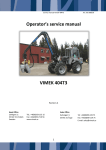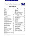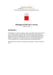
1
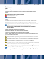
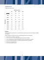
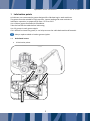
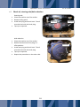
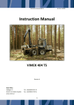
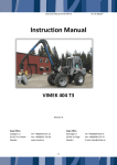
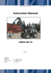
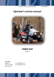
Operator’s service manual 404 T5 Operator's service manual VIMEK 404T5 Revision A Head Office Lidvägen 11 SE-922 31 Vindeln, Sweden www.vimek.se Tel: +46 (0)933-135 15 Fax: +46 (0)933-710 56 1 Art. No. 911291 Operator’s service manual 404 T5 Art. No. 911291 Service and maintenance 6.2 6.3 6.4 6.5 6.6 6.7 6.8 Maintenance .......................................... 3 Safety ...................................................................... 3 General ..................................................................... 3 Tightening torque..................................................... 4 Welding .................................................................... 4 1 1.1 1.2 1.3 1.4 1.5 1.6 1.7 1.8 1.9 2 2.1 2.2 2.3 2.4 2.5 2.6 2.7 2.8 2.9 2.10 2.11 3 3.1 3.2 3.3 4 4.1 4.2 5 5.1 5.2 6 6.1 Lubrication points ............................ 5 Articulated centre ......................................... 5 Stabilisation cylinder ..................................... 6 Steering cylinder ........................................... 6 K shaft ........................................................... 6 Bearing housing ............................................ 7 Lubrication points, steering axle ................... 7 Crane lubrication points................................ 7 Brake linkage ................................................. 8 Unit ............................................................... 8 7 7.1 7.2 7.3 7.4 7.5 7.6 7.7 7.8 7.9 7.10 7.11 Bolted joint ...................................... 9 Wheels, cab section ...................................... 9 Wheels, front section .................................... 9 Crane foot ................................................... 10 Clamp mounting ......................................... 10 Crane plate .................................................. 11 Clamp, front shaft ....................................... 11 Centre link ................................................... 12 Rear section gearbox .................................. 12 Drive shaft ................................................... 13 Crane's bolt joint ......................................... 13 Tool service points ...................................... 13 8 8.1 8.2 9 9.1 9.2 9.3 Battery .......................................... 14 Change the engine oil ................................. 16 Hydraulic oil check/change ........................ 16 Check the hydraulic oil level ....................... 16 Gearbox oil check ....................................... 17 Gearbox oil change ..................................... 17 Check oil, steering axle/hub reduction ....... 18 Change oil, steering axle/hub reduction .... 19 Filter .............................................. 21 Engine oil filter ........................................... 21 Filter, hydraulic oil cooler. .......................... 21 Filter hub sides ........................................... 21 Hydraulic oil return filter check .................. 22 Breather filter check ................................... 22 Fine filter circuit check. .............................. 22 Filter, fine filter circuit, change. ................. 22 Diesel filter change ..................................... 23 Checking and cleaning the engine cooler ... 23 Check air filter and coarse filter air can. ..... 24 Cab filter ..................................................... 24 Hydraulics ...................................... 25 General ....................................................... 25 Venting/pressure adjustment of LS line and main pressure ............................................. 25 Brake system .................................. 26 Back-up/parking brake ............................... 26 Bleeding/changing brake oil ....................... 26 Releasing brakes, front axle ....................... 27 10 Tyres .............................................. 28 General ....................................................... 14 Charging ...................................................... 14 Battery change ............................................ 14 10.1 10.2 Damage ...................................................... 28 Air pressure ................................................ 28 11 Safety equipment ........................... 28 Engine............................................ 14 11.1 11.2 11.3 Follow the service instructions and intervals in the engine instruction manual. ............... 14 Adjusting the valves .................................... 14 Fire extinguisher ......................................... 28 Sprinkler equipment ................................... 28 Safety belt .................................................. 28 12 Diesel heater .................................. 28 Fluids ............................................. 15 12.1 12.2 General ....................................................... 15 Coolant ........................................................ 15 General ....................................................... 28 Tool service points...................................... 28 13 Maintenance routines .................... 29 Oils ................................................ 16 13.1 13.2 Check the engine oil .................................... 16 2 Daily inspection .......................................... 29 Maintenance schedule ............................... 30 Operator’s service manual 404 T5 Art. No. 911291 Maintenance Safety Observe all safety provisions in the machine's instruction manual. Particularly important information in this service manual is marked with the following symbols: Risk of personal injury or damage to property Immediately stop any work. Important information General In order for the machine to function problem-free over a long lifespan, the service and maintenance must be carried out according to the instructions in this service manual. The machine must be regularly lubricated according to the chapter "Maintenance Schedule". Difficult circumstances can necessitate a shorter service interval. Be observant for any wear and tear, and for any situations that could lead to machine damage. Hydraulic components are sensitive to contamination. Observe strict cleanliness when servicing hydraulic components. Clean any leaks immediately, to avoid damage to the surroundings. Spent oil, coolant, battery fluid, etc. must be taken to the nearest recycling/deposit centre. Use environmentally-friendly diesel. Always turn off the engine during all service and maintenance work on the machine. Ensure that the motor cannot, in any circumstances, be accidentally turned on again. Secure machine parts during maintenance - risk of serious crushing injury Ensure that the crane and the machine are situated in a position where no parts of the crane or machine can move - risk of serious personal injury. Faults that are discovered must be resolved before continued driving, if there is a risk of personal injury or damage to property! If in doubt of the appropriate action for daily inspection, damage or larger repairs, contact your VIMEK dealer or service organisation. 3 Operator’s service manual 404 T5 Art. No. 911291 Tightening torque Tightening torque in Nm Dimensions Resistance class 4.6 8.8 10.9 12.9 M6 3.7 9.8 14 17 M8 8.9 24 33 40 M10 17 47 65 79 M12 30 81 114 136 M14 48 128 181 217 M16 74 197 277 333 M18 103 275 386 463 M20 144 385 541 649 M24 249 665 935 1120 Welding Welding work on machines that are under warranty shall be carried out according to VIMEK's instructions. When welding the machine or crane, the following measures must be taken: Disconnect the battery's + terminal. Ensure that there is functioning fire fighting equipment available. Clean sufficiently around the welding area so as to eliminate the risk of fire. Connect the earthing cable as close to the welding location as possible. Disconnect steering system Disconnect sprinkler system 4 Operator’s service manual 404 T5 Art. No. 911291 1 Lubrication points As lubricant, we recommend a grease designed for slide bearings in work machines. The grease must be suitable for high pressure, impact loading and must maintain its lubrication capacities in temperatures from -25°C to +50°C. Use a lithium grease fortified with EP additive. Take the load off the cables before lubricating. Use 2-3 pumps in each grease nipple. If it is difficult to insert the grease, it can help to move the cable backwards and forwards. Always replace sealed or broken grease nipples. 1.1 Articulated centre 4 lubrication points 5 Operator’s service manual 404 T5 1.2 Stabilisation cylinder 2+2 lubrication points … 1.3 Steering cylinder 1.4 2+2 lubrication points K shaft 2 lubrication points 6 Art. No. 911291 Operator’s service manual 404 T5 1.5 Bearing housing 1.6 1 lubrication point Lubrication points, steering axle 2 + 2 lubrication points … 1.7 Crane lubrication points 7 Art. No. 911291 Operator’s service manual 404 T5 1.8 Brake linkage 1.9 Art. No. 911291 2 lubrication points Unit A separate lubrication schedule applies to the harvester unit, see accompanying manual 8 Operator’s service manual 404 T5 Art. No. 911291 2 Bolted joint See section "Tightening torque" for the correct torque. When checking the bolted joint, to prevent stretching the bolts, do not apply the full tightening torque. 2.1 Wheels, cab section 2.2 Check: 4 pcs. Wheel bolts (2x). Wheels, front section Check: 4 pcs. Wheel bolts (2x). 9 Operator’s service manual 404 T5 2.3 Crane foot 2.4 Check 8 pcs. M20 Clamp mounting Check 4+4 pcs. M20 10 Art. No. 911291 Operator’s service manual 404 T5 2.5 Crane plate 2.6 Check 7 pcs. M18 Clamp, front shaft Check 2 pcs. M20 1 pc. M18 … 11 Art. No. 911291 Operator’s service manual 404 T5 2.7 Centre link 2.8 Check 1 pc. M20 4 pcs. M18 2 pcs. M12 Rear section gearbox Check 8 pcs. M14 12 Art. No. 911291 Operator’s service manual 404 T5 2.9 Drive shaft Check: 8 pcs. M10 joint pinion 3 pcs. M12 bearing housing 2.10 Crane's bolt joint See separate manual 2.11 Tool service points See separate manual 13 Art. No. 911291 Operator’s service manual 404 T5 Art. No. 911291 3 Battery 3.1 General Battery acid is very corrosive. Never short-circuit the battery poles. Risk of explosion. Use protective clothing and eye protection when working with batteries and battery acid. If battery acid gets onto skin or clothes, flush with copious amounts of water immediately. Do not disturb the battery cable shoes when the engine is running. Check: Battery fixing. That the poles and cable shoes are adequately protected. That the battery poles have not oxidised. Clean when necessary. Use contact grease on the poles. 3.2 Charging Stopping the main circuit breaker. Remove the cable shoe on the minus pole and then on the plus pole. Connect the charging equipment according to the battery charger's manual. Refit in the reverse order. Use contact grease on the poles. 3.3 Battery change Stopping the main circuit breaker. Remove the cable shoe on the minus pole and then on the plus pole. Fit new batteries. Refit in the reverse order. Use contact grease on the poles. 4 Engine For complete service and maintenance instructions, see the engine's separate manual! 4.1 Follow the service instructions and intervals in the engine instruction manual. 4.2 Adjusting the valves For valve adjustment instructions, see the workshop manual art. no.: 911055 14 Operator’s service manual 404 T5 Art. No. 911291 5 Fluids 5.1 General Check daily: That there are no leaks in the systems. Clean when necessary. That there are no damaged/broken hoses or connections. Change when necessary. 5.2 Coolant Never open the lid to the radiator when the engine is warm. Risk of burns. If propylene glycol is used, the coolant must be checked or changed at least once per year. Ready-mixed glycol is recommended. Follow the service and handling instructions in the engine instruction manual. 15 Operator’s service manual 404 T5 Art. No. 911291 6 Oils Old oil must always be managed and disposed of in accordance with applicable regulations. Pay attention to cleanliness to avoid the introduction of dirt particles into the system. The oils in a warm engine can be very hot. Risk of burns. For the right oil for your machine, see the oil specification or contact Vimek. Oil volumes and qualities can be found under technical data in the instruction manual. 6.1 Check the engine oil Check: Check the oil according to the instruction manual for the engine 6.2 Change the engine oil Change the oil according to the instruction manual for the engine 6.3 Hydraulic oil check/change Carry out continuous oil analysis through your oil supplier, to ensure the condition of the oil. Change when necessary. Always fill the oil through a filter. Change: Unscrew the oil plug under the hydraulic oil tank and collect the old oil. Screw the oil plug back in. Fill with new oil. See "Technical data" for the correct amount, and oil specifications for the correct type of oil. Check the oil level again after operating the hydraulic functions. 6.4 Check the hydraulic oil level Check the level in the hydraulic oil tank using the dip stick. The level should be 5-10cm under the maximum tank volume. The level can also be checked using the information menu on the instrument panel display. This shows 100% when the oil level is correct. 16 Operator’s service manual 404 T5 Art. No. 911291 6.5 Gearbox oil check Check: 6.6 Make sure the machine is on a level surface. Check the oil level in the sight glass on the front of the gearbox, under the transmission motor. Fill up as required, see "Change" below. Gearbox oil change Make sure the machine is on a level surface and with the hub reducers pointing downwards. Remove the protective plates from below the engine and gearbox. Unscrew the oil plug under the gearbox and plugs on the hub reducers and collect the old oil. Unscrew the magnetic plug. Metallic filings on the magnet can indicate gearbox damage. Contact your VIMEK dealer for an assessment. Screw the oil plug back in underneath the gearbox. Turn the hubs so that the drain ends up facing upwards, and fill the new oil through it. See "Technical data" and accompanying oil specifications for the correct amount and type of oil. Check the oil level in the sight glass on the front of the gearbox. Check that there are no leaks. Sight glass Bottom plug Plug hub reducer 17 Operator’s service manual 404 T5 Art. No. 911291 Check oil, steering axle/hub reduction 6.7 Steering axle Place the machine on a flat surface. Remove belly guard. Undo level plug and check level. The oil must be level with the level plug. Top up as required. Hub reduction Place the machine on a flat surface. Rotate the wheel until the plug is in a flat position. Undo level plug and check level. The oil must be level with the level plug. Top up as required. Repeat the procedure on the other side. 18 Level plug Level plug Level plug Operator’s service manual 404 T5 Art. No. 911291 Change oil, steering axle/hub reduction 6.8 Total oil volume in the axle, including hub reduction, is around 7 litres. The recommended hypoid oil is API GL5, MIL L2105 D. Position the machine on a flat surface before starting the procedure. 1 1 2 2 … 3 1. Oil filler inlet 2. Oil drain 3. Filling/draining hub reducer Remove the level plug (1) and the drain plug (2). Collect all oil and take it to a recycling station. Screw the drain plug (2) firmly in position. Fill with oil until up to the lower edge of the level plug. 19 Operator’s service manual 404 T5 Art. No. 911291 … Turn the wheel until the level plug on the hub reducer is pointing upwards. Loosen the plug to release any overpressure. Tighten the plug. Rotate the wheel until the plug is pointing downwards. Loosen the plug and drain the oil. Take the oil to a dump. Rotate the wheel until the plug is in a level position. Fill with oil up to the lower edge of the plug and screw in the plug. Repeat the procedure on the other side. 20 Operator’s service manual 404 T5 Art. No. 911291 7 Filter Pay attention to cleanliness to avoid the introduction of dirt particles into the systems. 7.1 Engine oil filter Filter change: Always replace the filter when changing the oil. Follow the instructions in the engine instruction manual. 7.2 Filter, hydraulic oil cooler. The best way of cleaning the filter is by rinsing it with water. Replace the filter when it becomes difficult to clean or is damaged. If necessary, blow the cooler element clean using compressed air or wash with water. A dirty cooler is the most common cause of hydraulic oil overheating. 7.3 Filter hub sides Check and, if necessary, clean the filters in the hub sides. The best way of doing this is by rinsing with water. Replace the filter when it becomes difficult to clean or is damaged. 21 Operator’s service manual 404 T5 Art. No. 911291 7.4 Hydraulic oil return filter check There are 2 hydraulic oil filters. A return oil filter for all the circulating oil in the system and a fine filter. The return oil filter functionality is tested when the oil reaches normal operating temperature. At full engine speed, the pressure gauge mounted on the return oil filter should not enter the red field. 7.5 Breather filter check A visual check of the breather filter mounted on the return oil filter. 7.6 Fine filter circuit check. An indication lamp lights on the machine's information display when the filter is 75% used. 7.7 Filter, fine filter circuit, change. Remove the filter cup and change the filter insert. 22 Operator’s service manual 404 T5 Art. No. 911291 7.8 Diesel filter change Filter change: Close the diesel filter stopcock. Empty the water separator as necessary. Loosen the filter. Pay attention to cleanliness. Fit a new filter. Vent the diesel system; see the section in the engine instruction manual. … 7.9 Checking and cleaning the engine cooler Open the bonnet to best be able to clean. If necessary, blow the cooler element clean using compressed air or wash with water. A dirty radiator is the most common cause of engine overheating. Open the bonnet to best be able to clean. 23 Operator’s service manual 404 T5 Art. No. 911291 7.10 Check air filter and coarse filter air can. Check hoses and hose connections. If the engine is able to draw air through leaks, it may result in engine damage. Replace the element if the filter indicator shows a pressure drop. 7.11 Cab filter The filter is placed on the cab ceiling. Change or clean the filter. The recirculation air filter is placed in the fan box; remove the cover to change the filter. Check: That the filter is clean and intact. Change when necessary. Recirculation filter Cab filter 24 Operator’s service manual 404 T5 Art. No. 911291 8 Hydraulics 8.1 General Check daily: That there are no leaks in the system. Clean when necessary. That there are no damaged/broken hoses or connections. Change when necessary. 8.2 Venting/pressure adjustment of LS line and main pressure LS/Main pressure Button … The hydraulic system's maximum pressure is adjusted by the hydraulic oil pump compensator. The LS pressure is around 20-25 bar; main pressure 220 bar. Fluctuations in the hydraulic system can be rectified by venting and adjusting the LS pressure. Vent by loosening the plug so that leakage occurs at the pump compensator when the engine is running. Carefully activate a function and let oil escape until it is free of air bubbles. Check LS pressure on the machine's information display. The engine must be running, with no functions activated. Check the main pressure by forcing the machine's stabilising function to run, forcing up the machine at maximum pressure. 25 Venting LS pipes Adjusting LS pressure Adjusting main pressure Operator’s service manual 404 T5 Art. No. 911291 9 Brake system 9.1 Back-up/parking brake Check that there are no leaks or worn hoses. The reserve / parking brake is activated when the machine's accelerator is in neutral. When the machine's gearbox is in neutral, it is this brake that holds the machine. 9.2 Bleeding/changing brake oil Bleed the brakes if they are applied unevenly or feel weak. Bleeding must take place on both sides, each one individually. Drain oil out of the axle until fresh oil emerges, approx. 2-3dl. 2 2 1 … … 3 4 5 … … Risky task! Remove belly guard (1) Open nipple (2) approx. ¼ turn (if the nipple is difficult to access, you can push swing damper (5) sideways). Use suitable equipment to collect oil (3, 4). Put in neutral and move the accelerator forwards or back. Release the pedal when only fresh oil emerges. Close the nipple, check that there are no leaks. Repeat on the other side. Reset the machine, do a test run and check the function of the brakes. 26 Operator’s service manual 404 T5 9.3 Art. No. 911291 Releasing brakes, front axle The machine's brakes must be unlocked during e.g. towing. 2 1 2 1 2 2 2 2 3 4 2 1. Apply a pressure of at least 13 bar to the brake port (1) (either via external equipment or by activating the machine's accelerator). 2. Undo 6 pcs. locking screws (2) (pos. as illustrated) 3. Undo the brake actuation screws (3) along the entire stroke. 4. Release the pressure at the brake port. 5. Fit the locking screws (2) for the bolts (4) 6. Lock the bolts (4) and tighten the locking screws (2) 27 Operator’s service manual 404 T5 Art. No. 911291 10 Tyres 10.1 Damage Check tyres visually. 10.2 Air pressure The wheel on the steering axle is filled with a saline solution. Tyre pressure 4 bar. Air pressure, tractor element 4 bar. 11 Safety equipment 11.1 Fire extinguisher Check daily: Pressure in the fire extinguisher. The extinguisher's pressure gauge must be within the green markings. 11.2 Sprinkler equipment Sprinkler equipment is an additional option. Follow the instructions in the separate sprinkler system instruction manual. 11.3 Safety belt A safety belt is an additional option. Check daily: That the belt locks, by pulling abruptly on it. That there is no damage to the belt. 12 Diesel heater The diesel heater is an additional option. 12.1 General Check daily, when in use: That the parts surrounding the heater are clean and well-ventilated. Risk of fire! Clean when necessary. 12.2 Tool service points See separate manual. 28 Operator’s service manual 404 T5 Art. No. 911291 13 Maintenance routines 13.1 Daily inspection Inspect the machine and crane daily in respect of safety and function. Daily inspection, lubrication and simple repairs can be carried out by the driver. Pay particular attention to: Noticeable defects or changes to the outside of the machine, e.g. cracks or damage in supporting parts. Leakage from the hydraulic system, damage to hoses or cables. Leakage from the engine. In dusty situations, the air filter, cab filter and cooler filter must be checked daily. If the diesel heater is used, the area around the heater exhaust system must be cleaned daily. Risk of fire. The service instructions for some points may be described in a different service manual. The following points must be checked every day. Cooling system coolant level Air purifier Engine oil level Water sediment draining Alternator/fan belt 7.2. Filter, oil cooler 7.3. Filter, hub sides 7.4 Check hydraulic oil filter 7.5 Check breather filter 7.9 Check radiator 7.10 Check air filter 7.11 Check cab filter 10.1 Tyre damage 10.2 Air pressure 11.1 Fire extinguisher 12 Diesel heater See separate Engine manual See separate Engine manual See separate Engine manual See separate Engine manual See separate Engine manual 29 Operator’s service manual 404 T5 Art. No. 911291 1.1 Articulated centre 1.2 Stabilisation cylinder 1.3 Control cylinder 1.4 Transmission shaft 1.5 Bearing housing 1.6 Steering axle 1.7 Crane 1.8 Brake linkage 1.9 Unit X X X X X X X X X Separate manual 1000 hrs / Annually 500 hrs 250 hrs 100 hrs 50 hrs 25 hrs 1. Lubrication points 1st service 13.2 Maintenance schedule X X X X X X X X X 2. Bolted joint 2.1 Wheels, cab section 2.2 Wheels, trailer section 2.3 Crane foot 2.4 Clamp bracket 2.5 Crane plate 2.6 Clamp, front shaft 2.7 Centre link 2.8 Rear section gearbox 2.9 Drive shaft 2.10 Crane 2.11 Tools X X X X X X X X X X X 3. Battery 3.1 General X 4 Motor 4.1 Engine maintenance X 5 Liquids 5.2 Coolant X X X X X X X X X X X X X X X 30 6.2 Change engine oil 6.4 Check hydraulic oil level 6.6 Gearbox oil change 6.8 Steering axle oil change X X X X X X X X 7. Filter 7.1 Engine oil filter change 7.8 Diesel filter change X X X X 9. Brake system 9.2 Bleeding brakes X X 10. Tyres 10.1 Air pressure X X 31 Separate manual 1000 hrs / Annually 500 hrs Art. No. 911291 250 hrs 100 hrs 50 hrs 25 hrs 6. Oils 1st service Operator’s service manual 404 T5