1
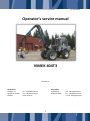
Service manual Vimek 404T3 Art. No 908318 Operator’s service manual VIMEK 404T3 Revision A Head Office Lidvägen 11 SE-922 31 Vindeln Sweden Sales Office Kyrkvägen 5 SE-841 31 Ånge Tel.: +46(0)933-135 15 Fax: +46(0)933-710 56 www.vimek.se 1 Tel: +46(0)690-619 75 Fax: +46(0)690-129 75 E-mail: [email protected] Service manual Vimek 404T3 Art. No 908318 Service and maintenance 1 1.1 1.2 1.3 1.4 1.5 2 6.13 Filter hub sides ..................................... 14 6.14 Check air filter and coarse filter air can. ................................................. 14 6.15 Check cab air filter. .............................. 15 6.16 Check the hydraulic oil level ................ 15 6.17 Check the engine’s oil level.................. 16 6.18 Change engine oil ................................ 16 6.19 Adjusting the valves ............................. 16 6.20 Change the fuel filter. .......................... 16 6.21 Venting the diesel system .................... 16 6.22 Fan belt ................................................ 18 6.23 Crane’s bolt joint.................................. 19 6.24 Tool service points ............................... 19 6.25 Back-up/parking brake......................... 19 6.26 Emptying the brake circuit ................... 19 6.27 Filling the brake circuit ........................ 20 6.28 Adjusting the brakes ............................ 21 Maintenance..................................... 3 Safety...................................................... 3 General ................................................... 3 Daily inspection ...................................... 4 Tightening torque................................... 5 Welding .................................................. 5 Battery .............................................. 6 2.1 General ................................................... 6 2.2 Check battery mounting, its terminals, and terminal protectors. ........................ 6 2.3 Charging ................................................. 6 2.4 Battery change ....................................... 6 2.5 Start-up help .......................................... 6 3 Hydraulics ......................................... 7 3.1 General ................................................... 7 4 7 Safety equipment ............................. 7 7.1 Upper and lower centre bearing brackets. .............................................. 22 7.2 Forward bushing, articulated centre. .. 23 7.3 Stabilisation cylinder ............................ 24 7.4 Steering cylinder .................................. 24 7.5 K axle (2 lubrication points), ................ 24 7.6 Bearing housing, .................................. 24 7.7 Drive tunnel joint cup .......................... 25 7.8 lubrication points steering axle ........... 25 7.9 Crane lubrication points ...................... 25 7.10 Rotator/Link ......................................... 26 7.11 Unit ...................................................... 26 4.1 Fire extinguisher ..................................... 7 4.2 Safety belt .............................................. 7 5 Diesel heater..................................... 7 5.1 General ................................................... 7 6 Maintenance routines ....................... 8 6.1 6.2 6.3 6.4 6.5 6.6 6.7 6.8 6.9 6.10 6.11 6.12 Lubrication points ........................... 22 General ................................................... 8 Checkpoints ............................................ 8 Wheel, bolt joint and air pressure.......... 8 Stabilisation bolts, crane plate ............... 9 Crane foot .............................................. 9 Bolt, forward bearing bracket ................ 9 Bolt joint clamps under front axle ........ 10 Bolts on upper and lower bearing brackets, articulated centre/rear section gearbox. ................................... 10 Rear section gearbox ............................ 11 Venting of LS line/adjusting the hydraulic pump pressure ..................... 12 Filter oil cooler. .................................... 13 Checking and cleaning engine cooler ... 13 8 Transmission ................................... 27 8.1 8.2 8.3 8.4 9 Gearbox oil........................................... 27 Changing oil Steering axle .................... 28 Changing oil hub reducer ..................... 28 Coolant................................................. 31 Maintenance schedule .................... 32 10 Spare parts ..................................... 33 2 Service manual Vimek 404T3 Art. No 908318 1 Maintenance 1.1 Safety Observe all safety provisions in the machine’s instruction manual. Particularly important information in this service manual is marked with the following symbols: Risk of personal injury or damage to property Immediately stop any work Important information 1.2 General In order for the machine to function problem-free over a long lifespan, the service and maintenance must be carried out according to the instructions in this service manual. The machine must be regularly lubricated according to the chapter "Maintenance Schedule". Difficult circumstances can necessitate a shorter service interval. Be observant for any wear and tear, and for any situations that could lead to machine damage. Hydraulic components are sensitive to contamination. Observe strict cleanliness when servicing hydraulic components. Clean any leaks immediately, to avoid damage to the surroundings. Spent oil, coolant, battery fluid, etc must be taken to the nearest recycling/deposit centre. Use environmentally-friendly diesel. Always turn off the engine during all service and maintenance work on the machine. Ensure that the motor cannot, in any circumstances, be accidentally turned on again. Secure machine parts during maintenance - risk of serious crushing injury Ensure that the crane and the machine are situated in a position where no parts of the crane or machine can move - risk of serious personal injury. Faults that are discovered must be resolved before continued driving, if there is a risk of personal injury or damage to property! If in doubt of the appropriate action for daily inspection, damage or larger repairs, contact your VIMEK dealer or service organisation. 3 Service manual Vimek 404T3 1.3 Art. No 908318 Daily inspection Inspect the machine and crane daily in respect of safety and function. Daily inspection, lubrication and simple repairs can be carried out by the driver. Pay particular attention to: Noticeable defects or changes to the outside of the machine, e.g. cracks or damage in supporting parts. Leakage from the hydraulic system, damage to hoses or cables. Leakage from the engine. In dusty situations, the air filter, cab filter, cooler and cooler filter must be checked daily. If the diesel warmer is used, the area around the warmer’s exhaust gas system must be cleaned daily. Fire risk. Check the following points daily: Oils Brake system Hydraulics Safety equipment Cooler Filter 4 Service manual Vimek 404T3 1.4 Tightening torque Tightening torque in Nm Dimensions Resistance class 1.5 4.6 8.8 10.9 12.9 M6 3.7 9.8 14 17 M8 8.9 24 33 40 M10 17 47 65 79 M12 30 81 114 136 M14 48 128 181 217 M16 74 197 277 333 M18 103 275 386 463 M20 144 385 541 649 M24 249 665 935 1120 Welding Welding must be done according to VIMEK’s instructions When welding the machine or crane, the following measures must be taken: Disconnect the battery’s + terminal Ensure that there is functioning fire fighting equipment available. Clean sufficiently around the welding area so as to eliminate the risk of fire. Connect the earthing cable as close to the welding location as possible. Disconnect steering system Disconnect sprinkler system 5 Art. No 908318 Service manual Vimek 404T3 Art. No 908318 2 Battery 2.1 General Battery acid is very corrosive. Never short-circuit the battery poles. Risk of explosion. Use protective clothing and eye protection when working with batteries and battery acid. If battery acid gets onto skin or clothes, flush with water immediately. Do not disturb the battery cable shoes when the engine is running. Check: Battery fixing. That the poles and cable shoes are adequately protected. That the battery poles have not oxidised. Clean when necessary. Use contact grease on the poles. 2.2 Check battery mounting, its terminals, and terminal protectors. 2.3 Charging Stopping the main circuit breaker. Remove the fuses to the sprinkler system, if such fuses are fitted Remove the cable shoe on the minus pole and then on the plus pole. Connect the charging equipment according to the battery charger’s manual. Refit in the reverse order. Use contact grease on the poles. Battery change Stopping the main circuit breaker. Remove the cable shoe on the minus pole and then on the plus pole. Fit new batteries. Refit in the reverse order. Use contact grease on the poles. 2.4 2.5 Start-up help Remove the fuses from the sprinkler system. Read the sprinkler system instruction book. 6 Service manual Vimek 404T3 Art. No 908318 3 Hydraulics 3.1 General Check daily: That there are no leaks in the system. Clean when necessary. That there are no damaged/broken hoses or connections. Change when necessary. 4 Safety equipment 4.1 Fire extinguisher Check daily: Best before date. Pressure in the fire extinguisher. The extinguisher’s manometer must be within the green markings. 4.2 Safety belt A safety belt is an additional option. Check daily: That the belt locks, by pulling abruptly on it. That there is no damage to the belt. 5 Diesel heater The diesel heater is an additional option. 5.1 General A diesel heater is available as an optional extra. If you have one installed, it is important that you keep the area around the heater free from combustible material and check carefully to ensure that there are no fuel leaks. Every day, open the protective plates under the nose of the machine and check daily before use: The area around the heater’s parts is free from material and fluids that may ignite. Check that the red protective sock fitted on the heater exhaust hose is intact and covers all the way down to the start of the hose at the diesel heater. 7 Service manual Vimek 404T3 Art. No 908318 6 Maintenance routines 6.1 General Periodic maintenance consists of regular cleaning and lubrication of moving parts. To avoid fires, the machine must be kept clean and any leaks immediately rectified. Filters and coolers must be kept clean so as not to reduce the lifespan of the machine. Equipment must be inspected on a regular basis for damage and abnormal wear. Any damage or abnormal wear found on the equipment must be repaired as soon as possible. 6.2 Checkpoints The crane, engine, optional extras and the unit all have separate manuals. Study these and follow the servicing instructions set out therein. 6.3 Wheel, bolt joint and air pressure The wheel on the steering axle is filled with a saline solution. Tyre pressure 2.5 bar The wheel on the tractor section is inflated to 2 bar 8 Service manual Vimek 404T3 6.4 Art. No 908318 Stabilisation bolts, crane plate The nut in contact with the steering axle is locked using lock fluid. Swing the crane to one side and check that there is no gap on either side. Adjust the joint if necessary. 6.5 Crane foot Check after first service, 500 hours and every 1000 hours thereafter. Draw 90% of the recommended tightening torque to avoid tensing the bolt 7 pcs. M20 1 pcs. M16 M20, 7 pcs. M16, 1 pc. 6.6 Bolt, forward bearing bracket 9 Service manual Vimek 404T3 6.7 Art. No 908318 Bolt joint clamps under front axle 4 pcs. M16 6.8 Bolts on upper and lower bearing brackets, articulated centre/rear section gearbox. Check after first service, 500 hours and every 1000 hours thereafter. Draw a max of 90% of the recommended tightening torque to avoid tensing the bolt 2 pcs. M18 12.9 and 4 pcs. M16 12.9. 2 pcs. M12 8.8 Note that the M16 bolts are located in the rear of the bearing bracket. 10 Service manual Vimek 404T3 Art. No 908318 6.9 Rear section gearbox Check after first service, 500 hours and every 1000 hours thereafter. Draw a max of 90% of the recommended tightening torque to avoid tensing the bolt 8pcs. M14 M14, 6 pcs. M14, 1 pc. both sides M14, 6 pcs. M14, 2 pcs. 11 Service manual Vimek 404T3 Art. No 908318 6.10 Venting of LS line/adjusting the hydraulic pump pressure The hydraulic system’s maximum pressure is adjusted by the hydraulic oil pump compensator. The LS pressure is around 20-25 bar; main pressure 220 bar. Fluctuations in the hydraulic system can be rectified by venting and adjusting the LS pressure. Power socket Vent by loosening the hose connection so that leakage occurs at the pump compensator when the engine is running. Carefully activate a function and let oil escape until it is free of air bubbles. Check LS pressure with a manometer on the machine’s power socket with the engine running and no function activated. Check the main pressure by forcing the machine’s stabilising function to run, forcing up the machine at maximum pressure. Adjusting main pressure Locking screw adjustment Locking screw adjustment Adjusting LS pressure Venting LS pipes 12 Service manual Vimek 404T3 Art. No 908318 6.11 Filter oil cooler. The best way of cleaning the filter is by rinsing it with water. If necessary, blow the cooler element clean using compressed air. A dirty cooler is the most common cause of hydraulic oil overheating. Replace the filter when it becomes difficult to clean or is damaged. 6.12 Checking and cleaning engine cooler Open the bonnet to best be able to clean. 13 Service manual Vimek 404T3 Art. No 908318 6.13 Filter hub sides Check and, if necessary, clean the filters in the hub sides. The best way of doing this is by rinsing with water. Replace the filter when it becomes difficult to clean or is damaged. 6.14 Check air filter and coarse filter air can. If necessary, clean and dry the inside of the air can. Blow compressed air from the inside under rotation. If soot or oil has become trapped in the filter, soak the filter in detergent for 15 minutes, rinse and then leave to dry. Replace the element every 6th wash or once a year. Check the hose and that the winged screw for the element is sitting correctly. If the engine is able to draw air through leaks, it may result in engine damage. 14 Service manual Vimek 404T3 Art. No 908318 6.15 Check cab air filter. Clean or replace the filter if necessary. 6.16 Check the hydraulic oil level The level should be around 5 cm under the maximum volume in the tank when the machine is level. Visual check of the breather filter, change as required. 15 Service manual Vimek 404T3 Art. No 908318 6.17 Check the engine’s oil level 6.18 Change engine oil From the factory, the engine is filled with Agrol Turbokombi 10W 30, 8.3 litres of oil. Undo the protective plate below the engine. Open the filler cover. Drain the engine oil into a container and take it to a dump. Remove the old filter using filter tongs. Spread a little oil on the filter gasket and screw tightly back into position. Screw the oil plug back in and fill with new oil. Check the oil level before starting the engine. Read the accompanying engine instruction manual for more information. 6.19 Adjusting the valves Read the accompanying engine instruction manual for more information. 6.20 Change the fuel filter. Shut off the fuel cock and remove the filter using filter tongs. Screw the new filter tightly in position by hand. 6.21 Venting the diesel system When venting, the diesel level in the tank must be higher than the venting points. Be aware that diesel can easily be spilled during venting. Clean up spills immediately! Never bleed a warm engine. Think about the fire risk! The fuel system must be vented: if the tank is driven dry of diesel when the filter or diesel hoses are changed. before starting the engine, if the machine has been out of use for a lengthy period. 16 Service manual Vimek 404T3 Venting: Fill up the diesel tank. Bleed the diesel pump by opening plug "3". Close plug "3" once only diesel comes out. 3 17 Art. No 908318 Service manual Vimek 404T3 Art. No 908318 6.22 Fan belt Machine equipped with single heater: For machines with AC, the generator is driven from the compressor’s pulley. Note that both the generator and compressor are first loosened. First tension the belt that drives the compressor and lock it. Then adjust the belt that drives the generator. 18 Service manual Vimek 404T3 Art. No 908318 6.23 Crane’s bolt joint See separate manual. 6.24 Tool service points See separate manual. 6.25 Back-up/parking brake Accumulator Oil filling plug Check valve Brake cylinder Check that there are no leaks or worn hoses. The back-up/parking brake is activated when the machine’s accelerator is in neutral and if the hydrostatic circuit becomes depressurised. When the machine’s gearbox is in neutral, it is this brake that holds the machine. The individual responsible for charging the brake pressure circuit or the accumulator must fully understand the system - contact your VIMEK dealer in case of queries. 6.26 Emptying the brake circuit The circuit must be emptied when towing or adjusting the brakes. Note that the circuit is charged with around 20 bars of pressurised hydraulic oil, use suitable protection equipment before you open the circuit. Empty the circuit by loosening the check valve and releasing the pressurised oil. Press together the cylinders long enough for the brakes to be released. 19 Service manual Vimek 404T3 Art. No 908318 6.27 Filling the brake circuit In addition to hand tools, a long hydraulic hose and a ¼" adaptor are also needed. Ensure that all adaptors and hoses are fixed. Remove the filling plug from the check valve. Remove the power socket from the valve unit and connect a long hose to the check valve. Start the engine, no hydraulic function may be activated. When the brake pressure manometer shows a value corresponding to the machine’s set LS pressure, then the circuit is filled. Unfix the hose and fix the power socket and plug. No hydraulic function may be activated when the circuit is filled. The pressure in the brake circuit will then be too high and cause damage and wear to the brakes. 20 Service manual Vimek 404T3 Art. No 908318 6.28 Adjusting the brakes The brakes must be adjusted if they are uneven or feel light. The brakes must be adjusted on both sides for a more even braking effect. (Adjust one side at a time): Lift up the machine so that both front wheels can turn freely. Loosen lock nut "1". Screw in adjusting screw "2" until the wheel can no longer move. Loosen slightly so that the wheel can turn freely. Tighten lock nut "1". Repeat the above process on the other side. Test drive and check the brakes’ function and that they engage evenly. 1 2 21 Service manual Vimek 404T3 Art. No 908318 7 Lubrication points As lubricant, we recommend a grease designed for slide bearings in work machines. The grease must be suitable for high pressure, impact loading and must maintain its lubrication capacities in temperatures from -25°C to +50°C. Use a lithium grease fortified with EP additive. Take the load off the cables before lubricating. Use 2-3 pumps in each grease nipple. If it is difficult to insert the grease, it can help to move the cable backwards and forwards. Always replace sealed or broken grease nipples. 7.1 Upper and lower centre bearing brackets. If there is a squeak coming from the upper hinge despite lubrication being applied, the pressure must be relieved before any further lubrication takes place. This is done by setting the unit down on the ground and applying pressure at the front of the machine’s nose using a jack. 22 Service manual Vimek 404T3 7.2 Forward bushing, articulated centre. 23 Art. No 908318 Service manual Vimek 404T3 7.3 Stabilisation cylinder 2+2 lubrication points 7.4 Steering cylinder 2+2 lubrication points 7.5 K axle (2 lubrication points), 7.6 Bearing housing, 24 Art. No 908318 Service manual Vimek 404T3 7.7 Drive tunnel joint cup 7.8 lubrication points steering axle 7.9 Crane lubrication points 25 Art. No 908318 Service manual Vimek 404T3 Art. No 908318 7.10 Rotator/Link 2 lubrication points N.B. If a brake link is fitted, other care instructions will apply 7.11 Unit A separate lubrication schedule applies to the harvester unit, see accompanying manual 26 Service manual Vimek 404T3 Art. No 908318 8 Transmission 8.1 Gearbox oil Check: Make sure the machine is on a level surface. Check the oil level in the sight glass on the front of the gearbox, the level must be high up on the sight glass. Fill up as required, see "Change" below. Change: Make sure the machine is on a level surface and with the hub reducers pointing downwards. Remove the protective plate under the engine. Unscrew the oil plug under the gearbox and plugs on the hub reducers and collect the old oil. Unscrew the magnetic plug. Metallic filings on the magnet can indicate gearbox damage. Contact your VIMEK dealer for an assessment. Screw back the oil plug under the gearbox and one of the plugs to the hub reducer. Turn the hub without the plug so that the drain ends up facing upwards, and fill the new oil through it. See "Technical data" for the correct amount and type of oil. Check the oil level in the sight glass on the front of the gearbox. Check that there are no leaks. Sight glass Magnetic plug Bottom plug Plug hub reducer 27 Service manual Vimek 404T3 8.2 Changing oil Steering axle 8.3 Changing oil hub reducer Art. No 908318 The oil capacity of the axle is approximately 4 litres, each hub reducer holding around 0.5 litres. The recommended hypoid oil is API GL5, MIL L2105 D. Position the machine on a flat surface before starting the procedure. 1. 2. 3. 4. Oil filler inlet Oil drain Breathing plug Filling/draining hub reducer 28 Service manual Vimek 404T3 Art. No 908318 Bleed the axle by loosening the air plug to release any overpressure Remove the level plug (2) and the drain plug (3). Collect all oil and take it to a recycling station. Screw the drain plug (3) firmly in position. Fill with oil until up to the lower edge of the level plug. Screw on the breath plug. 29 Service manual Vimek 404T3 Art. No 908318 Turn the wheel until the level plug on the hub reducer is pointing upwards. Loosen the plug to release any overpressure. Tighten the plug. Rotate the wheel until the plug is pointing downwards. Loosen the plug and drain the oil. Take the oil to a dump. Rotate the wheel until the plug is in a level position. Fill with oil up to the lower edge of the plug and screw in the plug. Repeat the procedure on the other wheel hub. 30 Service manual Vimek 404T3 8.4 Art. No 908318 Coolant To change coolant, ensure that the machine is cold and on a level surface. The ethylene glycol should be changed every other year. The propylene glycol must be changed every year. Coolant is filled through the upper hose until the system is full. 31 Service manual Vimek 404T3 Art. No 908318 2.2 Check battery 6.3 Wheel and air pressure 6.4 Stabilisation bolts 6.5 Crane foot 6.6 Front bearing bracket 6.7 Clamps 6.8 Bolts bearing bracket 6.9 Rear section gearbox 6.14 Air filter 6.15 Air filter, cab 6.18 Change engine oil 6.19 Adjusting valves 6.20 Changing diesel filter 6.23 Crane 6.24 Unit Lubrication 6.29 Bearing brackets 6.30 Bushing, articulated centre 6.31 Stabilisation cylinders 6.32 Steering cylinders 6.33 K axle 6.34 Bearing housing 6.35 Drive tunnel 6.36 Front axle 6.37 Crane lubrication points 6.38 Rotator/link 6,39 Unit X X X X X X X X X x x 7.1 Gearbox oil 7.2 Steering axle oil change 7.3 Hub reducer oil change 7.4 Coolant X X X x x x x x x x X X X x x x x x x x X X X X X X X X x X X X Separate manual 1000 hrs / Annually 800 hours 500 hrs 400 hours 200 hrs 100 hrs 50 hrs 25 hrs 1st service 9 Maintenance schedule x x x x x x x x x x x x x x x x x x x 32 Service manual Vimek 404T3 Art. No 908318 10 Spare parts For spare parts, contact your local Vimek 404T3 dealer. ! IMPORTANT! Only use original spare parts. Components produced by third-party manufacturers may cause operational stoppages and expose the operator to unnecessary risk. WARNING! Before performing maintenance on the machine, remember SAFETY FIRST. Make sure that the crane arm is fully extended and with chocks in order to eliminate the danger of crushing. 33 Service manual Vimek 404T3 34 Art. No 908318