1
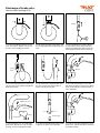
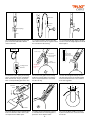
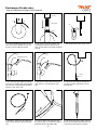
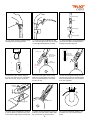
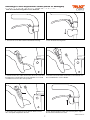
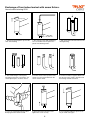
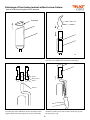
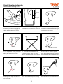
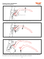
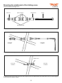
SERVICE MANUAL
Outdoor rollator Let’s Go Out
from TrustCare
Trustcare, Citadellsvägen 23, SE-211 18 Malmö, Sweden. Tel +46 40 15 61 20. [email protected] www.trustcare.se
1
TABLE O F C O N T E N T S
Exchange of brake wire
page 3
Exchange of wire adjustment screw
page 7
Exchange of front wheel swiwel with screw
page 8
Exchange of front wheel swiwel without screw
page 9
Unfold hook adjustments
page 10
Exchange of linkage arm for folding
page 11
Parking brake adjustments
page 12
Mounting the middle joint of the folding cross
page 13
2
Exchange of brake wire.
Year of manufacturing 2012.
A
B
A
B
B
B
Bushel
Washer
1. For disassembling the brake mechanism, unscrew the double screw A and
the two screws holding the fender.
2. Pull out the rear wheel, the fender and
the mounting plate with the brake mechanism.
3. First completely unscrew the adjustment knob to release the bushel. Then
pull up the handle tube entirely from the
front leg tube until the wire is stretched.
Bushel
Bushel
Washer
Washer
Washer
Locking
Locking
sleeve
sleeve
Locking
sleeve
Washer
Bottom plug
4. Unscrew the locking sleeve at the bottom end of the wire and disassemble the
brake mechanism..
5. Pull out the wire completely but leave
the sleeve in the tube which makes it
easier to insert the new wire..
Bottom plu
Bottom plug
6. Unscrew the two black screws and
pull down the brake housing so the brake
lever can be removed. Then remove the
wire completely.
Adjustment screw
king
king
cking
ve
ve
eve
king
ve
Brake lever
Housing
Bottom plug
Bottom
Bottomplug
plug
Handle tube
Bottom plug
7. Damaged parts such as handle tube,
brake lever, adjustment screw, or brake
housing can be exchanged if needed.
Locking
sleeve
8. To remove the bottom plug, press both
snaplocks on either side of the tube.
3
9. Insert the new wire through the screw,
brake lever, and handle tube. Screw back
the brake housing.
Formaaloop
loop
Form
New wire
Important:
Important:
Thispart
partof
oftt
This
wireon
ontop
top
wire
old wire
sleeve
Washer
Bottomplug
plug
Bottom
Bottom plug
Wire
10. Put the bottom plug on the wire and
press it into the handle tube. Add the
sleeve to the wire.
11. Put the end of the wire into the older
wire sleeve and use this as a guide to lead
the new wire into the rear leg.
Distance
Distance
Form asleeve
loop
Rear leg
sleeve
Form a loop
Form a loop
Form a loop
Lockingsleeve
sleeve
Locking
Cuthere
here
Cut
Wire guide
Wire guide
forming
Wire
guidethe
forming
the
loop
forming
the
loop
loop
Wire guide
forming the
loop
13. Mount the yoke, spring and locking
sleeve. Check the functon of the brake
when the wire has a loop, see picture.
Then cut the protruding part of the wire.
Distance
stancesleeve
Distance
sleeve
sleeve
Distance
sleeve
eeve
Wireguide
guide
Wire
formingthe
the
forming
loop
loop
Wire
Wire
Rearleg
leg
Rear
Brake
Brake
mechanis
mechanism
Important:
Important:
This part of the
Important:
Form
a
loop
This part
of on
the
wire
This
part top
of the
wire on top
wire on top
Important:
ThisBrake
part of the
Brake mechanism
Brake
wire
on top
mechanism
mechanism
Brake
Locking
sleeve
Wire guide mechanism
Cut here
forming the
loop
Important!
12. Push the handle tube down to the bottom and screw the height adjustment knob
back in place.
Insert the wire
Insert the
wire
guide
into
the
Insert
the
wire
guideDistance
into
the in the leg
channel
guide
into the
channelsleeve
in the leg
channel in the leg Insert the wire
guide into the
Insert the wire
channel in the leg
guide into the
channel in the leg
Important:
This part of the
wire on top
Brake
mechanism
Important!
14. Use the wire guide to form a loop
inside the rear leg. Make sure that the
wire is not pinched when it is inserted
into the rear leg.
Important!
15. Push the wire guide entirely into the
reat leg. Then push in the mounting plate
for the rear wheel into the same channel
in the rear leg profile.
Distance
sleeve
A
B
B
B
A
A
A
B
B
B
B
A
B
B
B
Important!
Important!
Important!
Important!
Important!
16. Before putting in the mounting plate,
make sure that the cavities in the yoke
correspond to the rubber parts.
17. Make sure that the distance sleeve
is included when the mounting plate is
pushed in. Then add the fender.
4
18. Screw the black double screw back
in place and fix the two screws that hold
the fender.
Exchange of brake wire.
Year of manufacturing from 2013 onward.
Rear leg
Rear leg
Rear legRear leg
A
Adjustment
A
screw
B
B
A
A
B
Brake lever
B
B
B
Wire guide
Wire guide
B
Wire guide
Wire guide
B
Slit
Slit
Slit
Slit
Fender
Fender
Washer
Fender Fender
Spring
1. For disassembling the brake mechanism, unscrew the double screw A and
the two screws holding the fender.
2. Pull out the rear wheel, fender, and
mounting plate with the brake mechanism, and the plastic wire guide inside the
Rear leg
rear leg.
A
3. Take off the brake yoke from the wire.
Distance
sleeve
Slit
Rear legWire guide
Handle tube
Adjustment
screw
B Adjustment screw B
Bushel
Slit
Brake
lever
Fender
Washer
Bottom plug
N.B.!
Wire
ug
Spring
Botto
Front leg tube
Botto
4. Unscrew the height adjustment knob
and move the handle tube a little upward.
Unscrew the housing around the brake
with the screw on the side.
5. Take out the end of the wire from the
lever and the screw through the side
slits.
6. Pull out the wire entirely through the
rear leg. Keep the spring and use it on
the new wire.
Handle tube
Adjustment screw
Rear leg
Form a loop
Bushel
Form a loop
Important:
This part of the
wire on top
Important:
This part of the
wire on top
Bottom plug Brake
mechanism
Wire guide
to form the
loop
Spring
Spring
7. Thread the spring over the upper end
of the wire and move it down to the bottom.
Bottom plug
Wire guide
to form the
loop
8. Push the upper end of the wire into
the rear leg. Use a screwdriver as help to
guide the wire into the upper tube.
5
Wire
Brake
mechanism
Front leg tube
9. Pull out the wire in the upper end and
put it into the handle tube all the way up
to the hole for the brake mechanism.
Form a loop
Bushel
Important:
Adjustmen
This part of the
wire on top
Brake
mechanism
Bottom plug
Wire guide
to formWire
the
loop
Spring
Bottom plug
10. Use a bent steel wire to pull the end of
the brake wire out through the hole.
Front leg tube
11. Put the wire into the brake lever and
the screw through the side slits. Exchange
any damaged details before assembly.
12. Skruva på kåpan, montera bottenpluggen i röret och skjut ner handtagsröret i
frambensröret hela vägen ner.
Bottom plug
Distance
sleeve
Rear leg
Handle tube
Insert rhe wireInsert rhe wire
rheguide
wire into the
guideInsert
into the
guide
into
the in the leg
channel
in the
leg
channel
Insert rhe wire
channel in the leg
Insert rhe wire
guide into the
guide into the
channel in the leg
channel in the leg
Form a loop Form a loop
Form a loop
Important: Important:
Form
a loop
Important:
This part
of theThis part of the
This
part wire
of theon top
wire on top
Important:
wire on top
Important:
This part of the
This part of the
wire on top
wire on top
Brake
Brake
Brake mechanism
mechanism
mechanism
Brake
Wire guide Wire guide
Brake
N.B.!
Wire
mechanism
to form
theguide
to form the
mechanism
loop to form the
loop
Wire guide
loop
Wire guide
to form the
to form the
loop
loop
Bushel
Form a loop
Bottom plug
Wire
Front leg tube
13. Mount the yoke and the spring on
the wire. Check the functon of the brake
when the wire has a loop, see picture.
ance
Distance
Distance
eeve
sleeve
sleeve
istance
sleeve
Rear leg
Handle tube
Adjustment screw
14. Use the wire guide to form a loop
inside the rear leg. Make sure that the
wire is not pinched when it is inserted
into the rear leg.
15. Push the wire guide entirely into the
reat leg. Then push in the mounting plate
for the rear wheel into the same channel
in the rear leg profile.
Distance
sleeve
A
B
B
B
N.B.!
N.B.!
N.B.!
Distance sleeve
A
A
B
A
B
B
B
B
A
B
N.B.!
N.B.!
Distance sleeve
Distance sleeve
Distance sleeve
Distance sleeve
16. Before the mounting plate is pushed
in, put the distance sleeve into the yoke.
Check that the rubber parts are included.
Distance sleeve
17. Make sure that the distance sleeve is
inside the yoke and that the rubber parts
don’t fall off. Put the fender in place.
6
18. Screw back the black double screw
A and the two screws B that hold the
fender.
B
Exchange of wire adjustment screw (whole or damaged)
iYear
rollatorn
Let’s Gofrom
Out2013
serie
2012 12 och framåt.
of manufacturing
onward.
1. Unscrew the screw that holds the black brake housing.
2. Push the brake housing down.
3. To take out the wire, make sure that the slits in the screw and
the brake lever correspond. If the screw is broken, use a small
screwdriver to turn it to the correct position.
4. The wire can now be taken out and the screw removed. Use
the screwdriver if the screw is broken.
5. Screw the new screw down to the bottom. Make sure the
slits correspond and put back the wire.
6. Push back the brake housing and screw it in place. Adjust
the wire tensin with the new screw.
www.trustcare.se
7
Exchange of front wheel swivel with screw fixture.
Joint
Year of manufacturing 2012.
Snap lock
Snap lock
Snap lock Snap lock
Snap lock
Snap lockSnap lock
Snap lock
Joint
Joint
1. Remove the black plastic cap over the
Joint
Joint
Joint
front swivel bearing
2. Unscrew the screw with an Allen key.
Put a screwdriver into the joint in the
plastic if the bearing rotates.
3. Pull out the front swivel and remove the
existing bearing.
4. The new bearing is in three parts.
One plastic part with screw fixture, one
shorter plastic part, one brass sleeve.
5. Put the sleeve in the top of the front
swivel. Put some grease between the
sleeve and the swivel.
6. Put the two halves together. Make sure
that the top of the swivel is locked inside
the bearing and will not fall out.
7. Press the new bearing into the tube.
Bump against the floor if needed.
8. Mount the washer and the screw.
Tighten the screw securely.
9. Put on the black plastic cap. If necessary fix it with some glue.
Joint
Joint
Joint
8
YTE AV FRAMGAFFELLAGER
Exchange of front wheel swivel without screw fixture.
Å LET’SYear
GO
OUT
of manufacturing
from 2013 onward.
2. KNACKA UT DE
BEFINTLIGA LAG
MED EN HAMMA
OCH EN METALL
SOM MELLANLÄ
1. LYFT AV PLASTLOCKET
Snap lock
BYTE AV FRAMGAFFELLAGER
PÅ LET’S GO OUT
BYTE AV FRAMGAFFELLAGER
1. LYFT AV PLASTLOCKET
PÅ LET’S GO OUT
BYTE AV FRAMGAFFELLAGER
Snap lock
PÅ
LET’S
GO OUT
1. LYFT
AV PLASTLOCKET
1. LYFT AV PLASTLOCKET
Snap lock
Snap lock
1. Remove
plastic
cap above the front wheel bearing.
3. TAthe
LOSS
LAGRET
FRÅN FRAMGAFFELN
OCH SÄTT PÅ DET NYA
LAGRET (3 DELAR).
3. TA LOSS LAGRET
FRÅN FRAMGAFFELN
OCH SÄTT PÅ DET NYA
LAGRET (3 DELAR).
3. TA LOSS LAGRET
FRÅN FRAMGAFFELN
OCH SÄTT
PÅ DET NYA
Plastic
LAGRET (3 DELAR).
2. KNACKA UT D
BEFINTLIGA LAG
MED EN HAMMA
OCH EN METALL
SOM MELLANLÄ
2. KNACKA
UT DET
BEFINTLIGA LAGRE
MED EN HAMMARE
2. KNACKA UT DET
OCH EN METALLBIT
BEFINTLIGA
LAGRET
MED
HAMMARE
SOMENMELLANLÄGG
OCH EN METALLBIT
SOM MELLANLÄGG
2. Knock the existing bearing out of the tube with a hammer.
Use a piece of metal between the hammer and bearing.
Plastic
Metal sleeve
Plastic
Metal sleeve
Plastic
Plastic
Metal sleeve
Plastic
Plastic
Groove
Metal sleeve
Groove
Plastic
Groove
Groove
3. Mount the new bearing. Put the metal sleeve on the swivel
and add some grease inbetween. Put the two plastic halves
together. Make sure that the groove locks the swivel inside.
4. Press the new bearing into the tube. Use a piece of wood
inbetween and knock it in with a hammer all the way up. Put
back the plastic cap.
9
Unfold hook adjustments.
Year of manufacturing 2012.
Seat
Opening
Wire
loop
Hook
Locking
peg
Locking peg
Black linkage arm
1. Below the seat of the rollator there is a
metal hook and a locking peg inside the
black linkage arm. The locking peg is a
spring dowel pin with a brass sleeve.
2. First make sure that the locking peg is
not damaged or missing. If it is missing it
must be replaced.
3. If the hook is not locking around the peg
and releases involuntarely although the peg
is intact it is because the hook is damaged
and has an incorrect shape.
Hook stuck
4. File carefully with a small round file to
make the tip of the hook deeper. Take it
little by little and test the function.
5. Test by lifting the rollator in the two
metal tubes that holds the seat. The hook
should not release. When the seat is
lifted in the hole the hook should release.
6. If the hook does not pass the peg
when the ends of the seat are pressed
down the hook will never lock around the
peg. The rollator will not unfold correctly.
7. File carefully on the bottom side of the
hook to give it a shape that allows it to
pass the peg. Take it little by little and
test the function.
8. When the ends of the seat are pressed
down the hook should pass the locking
peg and lock safely.
9. The wire that releases the hook when
the seat is lifted in the middle hole must
have a double loop to function correctly.
10
EXCHANGE OF THE PLASTIC LINKAGE ARM ON THE LET’S GO
Exchange of the linkage arm for folding.
1. Drill out t
that hold th
EXCHANGE OF THE PLASTIC LINKAGE ARM ON THE LET’S GO OUT ROLLATOR
1. Drill out the rivets
that hold the plastic arm in place.
2. Remove t
1. Drill out the rivets that hold the plastic linkage arm to the metal frame of the rollator.
3. In the pla
reinforceme
Put the met
2. Remove the plastic part. Keep the metal
reinformcement bar that is inside. new part.
2. Remove the damaged part.
3. In the plastic part there is a
reinforcement metal bar.
Put the metal bar inside the
new part.
4. Replace the damaged part
with the new one. On the right side
also mount the hook and the spring.
4. Replace th
with the new
also mount
5. Mount th
and nuts. Se
one drop of
5. Mount the screws, washers
and nuts. Secure the nuts with
one drop of Loctite.
3. Mount the new plastic arm with the metal
reinforcement bar. On the left side the hook for
folding should also be monted.
4. Mount the parts using screws, washers, and nuts. Add a drop of Loctite to fix
the nuts.
11
Citadellsv
Parking brake adjustments.
Year of manufacturing 2012.
Brake lever
A
Brake lever
A
A
Brake lever
Brake housing (cross section)
Brake housing (cross section)
Brake housing (cross section)
Brake wire
1. This is the function of the brake system on Let’s Go Out. When the brake lever is pulled up (A) the wire is stretched and the rollator
Brake wire
brakes. The parking prake is activated by pushing the lever down so it will lock in lowest position.
Brake wire
B
B
B
C
C
C
2. When the lever is pushed down th wire is stretched. The bottom end of the lever falls down into the cavity (C) and locks.
D
D
D
3. If the lever does not lock in the cavity, remove the two screws in the brake housing and push the housing down. Behind one of
the screws there is a washer, don’t lose it. File the corner at (D) to make it sharper so it will lock better in the cavity. If the brake
lever still does not lock, there could be a damage inside the brake housing and it must be replaced.
12
Mounting the middle joint of the folding cross.
Year of manufacturing 2012.
Dome nut
plastic washers
Metal sleeve
Screw
Brickor av metall
1. These are the parts of the joint and how they should be mounted together.
Front side
of rollator
Rear side
of rollator
2. The tubes of the folding cross should be placed between the washers according to this sketch.
Metal sleeve
Front side
of rollator
Rear side
of rollator
3. Tighten the dome nut securely. Fix the nut with a drop of Loctite so it will not fall off. The metal sleeve serves as a fixture peg for
the hook when the rollator is folded.
13