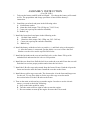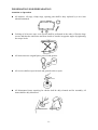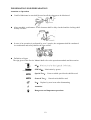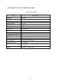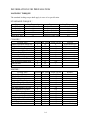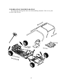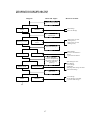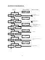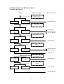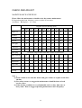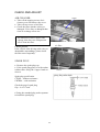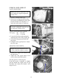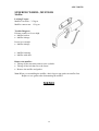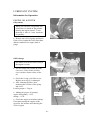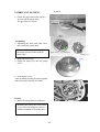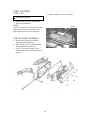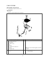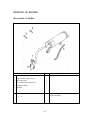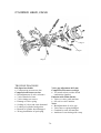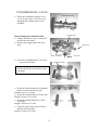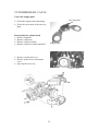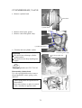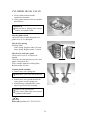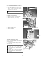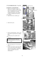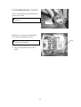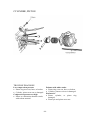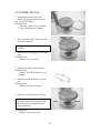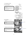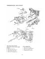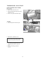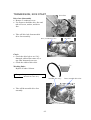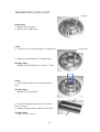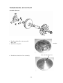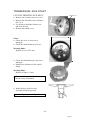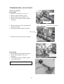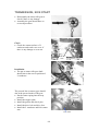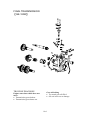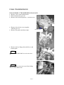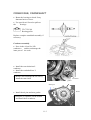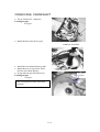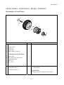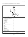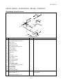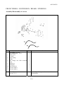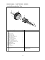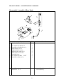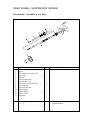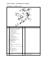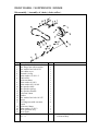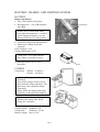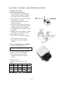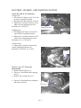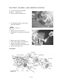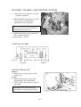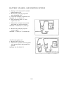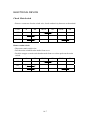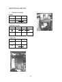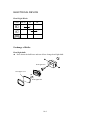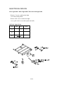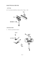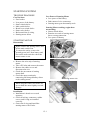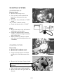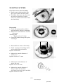
1
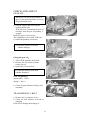
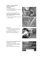
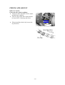
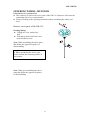
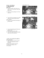
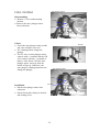
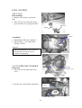
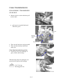
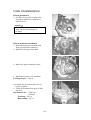
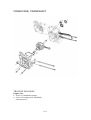
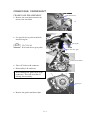
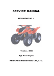
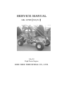
SERVICE MANUAL GK-125R【92/61】 July 04 High Power Engine HER CHEE INDUSTRIAL CO., LTD. Preface The Service Manual in reference is provided as the technical information for checking and preparation of ADLY GK-125R GO-KART and the edit description is given in diagrams with " Operation Sequence ", " Highlights " and " Checking Arrangement " for reference of the service staffs. The information, illustrations or contents included in this manual may be different with the actual scooter in case specifications are changed. Your understanding will be appreciated. HER CHEE INDUSTRIAL CO., LTD. INDEX Information for preparation 1 Muffler, Cover parts 2 Check and Adjust 3 Lubricant system 4 Fuel system 5 Remove of engine 6 Cylinder head, Valve 7 Cylinder, Piston 8 Transmission, Kick start 9 Final transmission 10 Crankcase, Crankshaft 11 Front wheel, Brake, Suspension, steering 12 Rear wheel, Brake, Suspension 13 Battery, Charge, and Ignition system 14 Starting system 15 Wiring diagram 16 ASSEMBLY INSTRUCTION 1. 2. (For GK-125R ) Take out the battery and fill with acid liquid. Pre-charge the battery will extend its life. The preparation and charge procedure is based on the battery’s instruction. Install the rear wheels and parts in the following order: A. 16x40x5mm washer. B. 16mm hex-bolt (torque 750~950 kg-cm, 74~93 N-m). C. Cotter pin (open up the end after installed). D. Rubber cap. 3. Install the front wheels and parts in the following order: A. 12x40x4.5mm washer. B. 12mm hex-bolt (torque 300~350kg-cm, 29.5~34N-m). C. Cotter pin (open up the end after installed). D. Rubber cap. 4. Install the battery with the red wire to positive (+) and black wire to the negative (-). After the battery is connected, put the plastic cover on it. Place the steel bracket over the cover and tie up with 2 hex-bolts. 5. Install the fuel tank on the rear rack and fuel valve on the frame. Fill up with unleaded fuel and turn the fuel valve to ON position. 6. Install the seat from front. Pull the lock lever under the seat and fit into the seat rail. Push back to set into proper position and release the lock lever. 7. Install the L/R roller cage tube started from the front of frame. Push the clip on the frame and set tube onto the frame. Install the rear tube to the frame. 8. Install the top roller cage cross tube. The shorter tube is in the front and longer one for the rear. Tie-up 4 hex-bolts to fix the top roller cage cross bar and 4 hex-socket bolts to fix the L/R tube on the frame. 9. Turn on the main switch and try to start the engine. In order to use the electric starter, you need to check the following: A. Step on the brake pedal for safety. B. Turn the main switch to right in order to start the engine. C. Do not continue to start up the engine for more then 10 seconds. P.D.I. (Pre-Delivery Inspection) (For GK-125R ) 1. Record the frame and engine number into the owner’s manual. 2. Check that all tires have correct pressure specified on the tire or in the owner’s manual. 3. Engine oil ( 4 stroke, 10W/40 ) is enough. 4. Battery is installed properly. 5. All brake cables are adjusted properly. 6. Fuel tank has enough gasoline to operate. 7. Check the suspension and drive chain for proper setup. 8. Check that all electrical components and lights are working properly. 9. Make sure that the owner’s manual and tool bag are installed properly. INFORMATION FOR PREPARATION Attention on Operation z All washers, oil rings, clamp rings, opening pins shall be duly replaced by a new item when dismounted. z Locking of all screws, nuts, cross screws shall be performed in the order of first the large screws and then the small ones and from inside to outside in opposite angles by tightening the torque locks. z All items must use original parts, pure oil and greases. z All service shall use special tools and general tools to repair. z All dismounted items requiring for checks shall be duly cleaned and for assembly, all items shall be duly lubricated. 1-1 INFORMATION FOR PREPARATION Attention on Operation z Certified lubricants in cans shall be used on all the elements to be lubricated. z After assembly, performance of all elements shall be duly checked and the locking shall be duly verified. z In case of an operation is performed by over 2 people, the assignment shall be conducted in coordination and safety shall be the first priority. z Definition of signs: The sign given in the Service Manual shall refer to the operation methods and observation. OIL:lubrication by designated lubricant GREASE: Lubrication by grease Special Tool: Parts on which special tools shall be used General Tool: General tools shall be used New: Replace by new items after dismounting Attention Dangerous and important operations 1-2 INFORMATION FOR PREPARATION SPECIFICATION TYPE GK-125R LENGTH 1780 mm WIDTH 675 mm HEIGHT 1160 mm WHEEL BASE 1255 mm NET WEIGHT 160 kg ENGINE TYPE 4-STROKE, Single Cylinder COOLING AIR COOLED DISPLACEMENT 124 C.C. BORE×STROKE 52.4×57.8 COMPRESSION RATIO 9.2:1 IGNITION C.D.I STARTER ELECTRIC / KICK SUSPENSION Hydraulic Shock Absorber TRANSMISSION AUTOMATIC TIRE Front 18*7-7 Rear 18*9.5-8 Front: Drum Rear: Disc BRAKE 1-3 INFORMATION FOR PREPARATION LOCKING TORQUE The standard locking torque shall apply in case of no specification. STANDARD TORQUE: Type Locking Torque (kg-m) 5mm Bolt, Nut 0.5 6mm Bolt, Nut 1.0 8mm Bolt, Nut 2.2 10mm Bolt, Nut 3.5 12mm Bolt, Nut 5.5 Type Locking Torque (kg-m) 5 mm Screw 0.4 6 mm Screw 0.9 6 mm Face Bolt, Nut 1.2 8 mm Face Bolt, Nut 2.7 10 mm Face Bolt, Nut 4.0 CHASSIS: Locking Place Handle bar bottom flange nut Ball joint fixed nut Engine mounting flange nut Engine mounting bracket bolt Foot rest flange bolt Rear swing arm fixed nut Rear brake panel flange bolt Front suspension fixed nut Rear suspension flange bolt Front rim nut Rear rim nut Quantity Dia. (mm) Torque (kg-m) 1 14 8 4 10 4.0 4 8 3.5 2 10 4.0 6 8 4.0 1 14 9 4 12 7 4 10 4.0 2 10 4.0 2 12 7 2 16 11 Remark Nylon insert type Nylon insert type Nylon insert type Nylon insert type ENGINE: Locking Place Cylinder Head Bolt A Cylinder Head Bolt B Oil Filter Cap Exhaust Cylinder Bolt Muffler Flange Fixed Bolt Muffler Bracket Fixed Bolt Cam Shaft Holder Face Nut Valve Adjuster Fixed Nut Gear Oil Releasing Bolt Clutch Cover Fixed Nut Drive Face Ass’y Fixed Nut Pri. Fixed Sheave Fixed Nut ACG Fly Wheel Fixed Nut Spark Plug Starter Clutch Lock Nut Quantity Dia. (mm) Torque (kg-m) Remark 1 8 0.9 Stud bolt side 1 8 0.9 1 30 1.5 2 6 0.9 Stud Bolt 2 6 1.2 2 8 3.5 4 8 2.0 2 5 0.9 2 8 1.3 1 12 5.5 1 12 5.5 1 12 5.5 1 12 5.5 1 10 1.2 1 22 9.5 Counter Clock type 1-4 INFORMATION FOR PREPARATION The following drawing that shows the disassembling situation of the cover parts for GK-125R Go-Gart. 1-5 INFORMATION FOR PREPARATION REVOLUTION NOT SMOOTH , LOST POWER Diagnose Check and Adjust start engine and go up speed slight engine speed go up engine speed can't go up fully adjusting ignite timing ignite timing is correct Reason of Trouble air cleaner blocking fuel supply isn't smooth air hole of air tank blocking exhaust pipe blocking auto.plunger starter damage film of carburetor damage fuel cup damage C.D.I damage pulser coil damage ignite timing isn't correct adjusting valve gap is not correct valve gap is correct valve gap adjusting isn't correct valve set over abrade valve gap isn't correct testing compression pressure compression pressure is normal valve set damage cylinder, piston abrade cylinder gasket leakage valve timing isn't correct compression pressure is too low check carburetor blocking ? no blocking cleaning carburetor blocking loosen spark plug and check spark plug normal cleaning the stain spark plug type isn't correct spark plug stain check the oil quantiity of crankcase is too rich or dirty? oil quantity is normal oil quantity is too rich oil flowing is too rich oil flowing is too lean oil doesn't circulate check cylinder head lubricating ? normal oil tubing blocking oil supply is too lean abnormal engine over heat normal over heat increase engine speed or continue turning at high speed no knocking knocking continue 1-6 cylinder, piston abrade mixutre gases is too lean carbon residue in combustion chamber is too more igniting time is too earily fuel isn't good clutch sliding mixutre gases is too lean carbon residue in combustion chamber is too more igniting time is too earily fuel isn't good INFORMATION FOR PREPARATION REVOLUTION NOT STABLE (LOW R.P.M.) Diagnose Check and Adjust Reason of Trouble ignition timing adjusting normal C.D.I damage pulser coil damage abnormal adjust the carburetor fuel adjuste screw adjusting is correct mixture gases too lean (loosing screw) mixture gases too rich (locking screw) adjusting isn't correct carburetor sucking air no sucking air sucking air loosen spark plug, connecct with spark cap and contract with frame, check the spark plug sparking ? sparking normal sparking abnormal gasket damage the screw of carburetor is loosen (-) pressure tube broken spark damage or stain C.D.I damage A.C.G damage coil damage spark plug cable damage odr short main switch damage check A.C.G normal A.C.G damage air hole damage or blocking (-) pressure tube damage abnormal end 1-7 INFORMATION FOR PREPARATION REVOLUTION NOT SMOOTH(HIGH SPEED) Check and Adjust Diagnose Reason of Trouble adjusting ignite timeing normal C.D.I damage ACG pulse coil damage abnormal adjusting valve gap normal adjusting isn't correct valve set damage abnormal check fuel cup supply normal ? normal fule filter blocking air hole of fuel tank blocking fuel cup damage fuel of tank is too less abnormal carburetor blocking cleaning no blocking blocking check and adjust valve timing valve timing is correct camshaft gear mark position is not correct valve timing isn't correct check the spring of valve normal spring broken or elastic deformation spring damage end 1-8 INFORMATION FOR PREPARATION CHARGE ABNORMAL Check and Adjust Diagnose Reason of Trouble start engine and measure voltage of the two terminal for battery voltage of battery can't go up voltage of battery is normal battery damage measure the resistance of ACG coil coil damage terminal damage YL wire damage measure value too high normal check the regulator battery have voltage battery have not voltage R wire damage check socket of regulator loosen ? normal regulator damage socket damage abnormal ACG damage (over charge) check the voltage between regulator and frame main switch at ON the battery have voltage main switch at ON the battery have no voltage GR wire broken check the socket of regulator normal socket damage socket loosen regulator damage 1-9 INFORMATION FOR PREPARATION SPARK PLUG NO SPARKING Diagnose Check and Adjust Reason of Trouble change spark plug and check again no sparking or weak the previous spark plug damage sparking strong check spark plug, cap, ignition coil loosen? loosen no loosen spark plug cap loosen check C.D.I unit socket loosen ? normal abnormal socket damage check the terminal of C.D.I unit unimpeded? measure resistance abnormal normal check relate spare parts normal main switch damage pulser coil damage coil damage lighten coil damage abnormal main switch damage socket, joint connect abnormal change CDI unit normal the previous C.D.I unit damage abnormal change ignition coil abnormal the previous coil damage 1-10 CHECK AND ADJUST INFORMATION WARNNING * Do not start the engine at a close zone, because the exhaust gases from the engine including some noxious emission such as CO, HC, NOx... etc. that can result serious damage for ealth. * Strictly prohibit using any flammable thing in the working zone, because that can rise fire easily. ENGINE: ITEM Throttle Free Play Spark Plug Gap Spark Plug Type Valve Gap Idle Speed Engine Oil Capability Gear Oil Compression Pressure Ignite Timing SPECIFICATION 2~6 mm 0.6~0.7 mm C7HSA CR7HSA 0.06mm 0.10mm 1700±100 rpm 0.9 L 0.75 L 350 cc 300 cc 12.8kg/cm2 13° BTDC ±2° REMARK without resistance with resistance intake valve exhaust valve resolve the engine only change engine oil resolve the gear only change gear oil 570 RPM 1700±100 rpm CHASSIS: ITEM Parking Brake Free Play Front Tire Pressure Rear Tire Pressure Torque of Front Tire Nut Torque of Rear Tire Nut SPECIFICATION 10~20 mm 1.68 kg/cm2(24psi) 1.68 kg/cm2(24psi) 3.5 kg-m 11.0 kg-m 2-1 REMARK CHECK AND ADJUST MAINTENANCE SCHEDULE Please follow the maintenance schedule to do the routine maintenance. I: Inspection and clean, lubricate, correct, replace if necessary. A: Adjust. R: Replace. C: Clean Regular Service Mileage (km) 1000 2000 3000 4000 5000 6000 7000 8000 9000 10000 11000 12000 Engine oil R R R Oil filter R R R R C R R R C R R Gear oil R R A A Carburetor Air cleaner I A A I C R R Clean the plug for each 3000 km, replace it if necessary. I I I I I I Belt I I I I I I I Suspension I I Nuts, bolts I I Tire Steering A I Spark plug Brake system A R C Fuel filter Valve gap R I I I I Note: (1) If the vehicle is new then the motor and gear oil have to replace at the first 300 km. (2) For safety reason, we suggest the maintenance should be done at local service center. (3) If the driving condition is very abominable such as rainy, dust zone or heavy load... that we suggest operating maintenance more frequency. 2-2 I I CHECK AND ADJUST FUEL FILTER • The filter is located underneath the carburetor. • Check the fuel pipe. If the tube has any damage then change it. fuel filter WARNNING * Smoking prohibited fuel cup THROTTLE LEVER PLAY • Check the throttle lever operating whether is smoothly. • Check the throttle lever play whether is normal. The main adjusting nut for throttle play is on the side of carburetor. • Loose the fixed nut and adjust the play nut to proper position. Play nut The micro-adjusting nut for the throttle play is under the throttle grip. • Removing the prevention dust cover of throttle cable, loose the fixed nut and adjust the play nut to proper position. Fixed nut 2-3 CHECK AND ADJUST AIR CLEANER screw • Take-off the tapping screws of air cleaner cover and remove the cover. • Take-off two screws of air filter. • Check the filter whether is dirty or damaged. If it‘s dirty or damaged then clean it or change a new one. * The material of filter is paper with sponge, thus don‘t use compression air to clean the filter. air cleaner cover air filter Check period: If the vehicle often driving at the rainy or abominable surroundings, please check the filter more frequently. SPARK PLUG • Remove the spark plug cap. • If the spark plug grimy or with carbon residue then using the copper brush to clean it. screw Spark plug specification C7HSA:without resistance CR7HSA:with resistance Check the gap of spark plug Gap:0.6~0.7 mm • Using the standard plug socket spanner to install the spark plug. 2-4 CHECK AND ADJUST VALVE ADJUSTING * When you check or adjust the valve, do it at the low engine temperature (about 35°C) • Remove cylinder head cover. • Rotate the cooling fan and keep the gear mark of camshaft aim at the TDC position and the ACG flywheel “T” mark aim at the mark of crankcase. * When you adjusting the valve, don’t invert the crankshaft, otherwise can not adjust the exhaust valve. VALVE GAP CHECK & ADJUST Valve gap: IN. :0.06 mm EX. :0.10 mm • Loose the fixed nut and rotating the adjusting nut reach to the proper gap. • Screw the fixing nut and check the gap again. • Using the valve gap adjuster to adjust the valve gap. ADJUSTING IDLE SPEED * Engine idle speed adjustment have to do it when the engine is warm. • Starting the engine and connect with the rpm meter. • Adjust the idle speed adjust screw reach to the normal idle speed. valve screw adjust tool The idle speed is 1700±100 rpm. If the idle speed is unstable or slightly pull the throttle the engine does not go smoothly then adjust the throttle valve stopper screw. throttle stopper screw 2-5 CHECK AND ADJUST IGNITION TIMING The ignition system of this vehicle is controlled by C.D.I unit, thus don‘t need to adjust anything. If the ignition timing isn’t correct then checking the ignition system whether normally. • Removing the L side cover. • Removing the rubber bung. • Using the timing light to check the ignition timing. The mark of crankcase aim at the “F” mark of flywheel, when the engine speed running at idle. Timing light IGNITION PERIOD • Using the timing light to check the ignition period. • Keep the engine speed about 5000rpm, if the flywheel mark aim at the enter angle mark of crankcase then the ignition period is correct. CYLINDER PRESSURE • Remove the spark plug. • Install the pressure gauge. • Open the throttle and press the electric start button. The normal cylinder pressure is about 128kg/cm2. (570 rpm) If the cylinder pressure is too low then check the following items: - Valve leakage? - Valve gap is too tie? - Cylinder head gasket is damage? - Piston ring wear-out? - Piston, cylinder wear-out? If the cylinder pressure is too high then check the combustion chamber and the top face of piston whether with too much carbon residue. 2-6 CHECK AND ADJUST GEAR OIL Oil quantity check bolt / washer * When you will check the quantity of gear oil, the main stand have to rise at the ground (flat) level. • Stop the engine and removing the quantity check bolt. If the oil level is around the bottom of bolt hole, then the gear oil quantity is enough. Refill the gear oil if it too less. The standard gear oil is SAE 85W/140 • Install the quantity check bolt. * Confirm the washer of the bolt whether damage. Chang the gear oil: • Take-off the quantity check bolt. • Remove the oil-release bolt and release the oil. • Install the oil-release bolt. oil release bolt / washer oil check hole * Confirm the washer of the bolt whether damaged. Gear oil quantity: disassemble:350 c.c. change:300 c.c. • Check all parts whether leaking, after assembly. TRANSMISSION V-BELT transmission belt • Remove the L crankcase cover. • Check the belt whether wear-out or chapping. If the belt is damage then change it. 2-7 CHECK AND ADJUST BRAKE SYSTEM Front brake • Check the brake pads If the brake pad has any dint or wearing very serious then change it. • Check the quantity of brake oil Make the steering straightly, check the brake fluid whether keep between the upper and lower level. • Refill recommended DOT-3 brake oil when necessary. Rear brake • Follow the front brake procedure to check the brake pads, disk, and oil. z Check the brake disk If the brake disk wear (thickness less than 3mm) or chap then change it. Check the play of parking brake lever normal play:10~20 mm If the play of the rear brake over the normal value then adjust the adjusting nut of rear brake. engine stopped then check the lining. parking brake leve 2-8 CHECK AND ADJUST TIRE, RIM • Check the tires whether have any nail, broken…etc. • Check the tire pressure. * The normal tire pressure Front tire :1.68 kg/cm2(24psi) Rear tire:1.68 kg/cm2(24psi) • Checking the shaft and nut of front wheel whether loosen. • Checking the nut of rear wheel whether loosen. STEERING • Turning the steering from right side to left side, check the steering operating. • Be sure the wiring and cable does not affect the steering handle. • Check the ball bearing on bottom of steering column whether is loose. 2-9 CHECK AND ADJUST DRIVE CHAIN Check the drive chain condition. z The drive chain should be check, adjust, and lubricate regularly. z The free play of the drive chain should be between 20~30mm up and down. z When install the chain clip, beware the clip direction. 20~30mm 2-10 ADLY MOTO STEERING WHEEL, MUFFLER Information for preparation z Don‘t enforce to remove the cover parts of the GK-125, otherwise will cause the connecting nail of cover parts broken. z Please according to the operating instruction when assembling the cables and wires Remove cover parts of the GK-125 Steering Wheel: z Taking off 3 hex washer face bolt z Disconnect main switch wire and neutral indicator wire. Note: When assembling the above parts that follow the opposite sequence of disassembling. Attention: * When assembling the above parts, please confirm the connecting status of join section. Note: When you assembling the above parts that follow the opposite sequence of disassembling. 3-1 ADLY MOTO STEERING WHEEL, MUFFLER Muffler: Locking Torque: Muffler fixed bolt:3.5 kg-m Muffler connect nut:1.2 kg-m Trouble Diagnose: Exhaust sound level is too high • Muffler broken • Muffler leakage Power isn‘t enough • Muffler leakage • Muffler blocking • Muffler with dent Remove the muffler: • Taking-off the nuts that connect to the cylinder. • Taking-off the bolt that fix to the frame. • Remove the muffler and gasket. Note: When you assembling the muffler, don't forget to put gasket on muffler first. Replace a new gasket after dismounting the muffler. MEMO 3-2 LUBRICANT SYSTEM TROUBLE DIAGNOSE Engine burn • No oil pressure or pressure too low • Oil thoroughfare blocking • Oil type isn‘t correct Oil quantity reduced • Normal consumption • Oil leaking • Piston ring wear-out or installed wrong • Rubber seal of valve wear-out 4-0 LUBRICANT SYSTEM Information for Operation ENGINE OIL & FILTER Oil quantity * When you check the oil quantity, the vehicle have to stand on flat ground. * Starting the engine about 2~3 min.. then stop it. After 2~3 min. check the oil quantity. • Remove the oil level gauge and check If the oil level under the lower limit then add the standard oil to upper limit of gauge. oil level gauge Oil Exchange * The motor oil will flow more easily if the engine is warm. • The oil release nut is under R-crank case cover. Take-off the oil-filter cover can have better release of the oil. Oil filter cover • Check the O-ring of oil filter cover. Replace new ring if it’s damaged. • After cleaning the filter, then mounting the oil filter, filter spring and cover. Locking torque: 1.5 kg-m • Adding the proper oil quantity: engine disassembly:0.9L. change:0.75L • Check the engine oil whether leaking. If not then starting the engine at idle speed for few minutes and checking the oil level again. O-ring 4-1 LUBRICANT SYSTEM Pulsar coil OIL PUMP Remove • Remove the fan and ACG. • Take-off 5 bolts on R. crankcase cover and remove it. ACG coil R crankcase cover • Remove the gasket and the dowel pin • Remove the starting clutch gear and starter clutch TLCT125-04 Dowel pin Use special tool to loose the starter clutch lock nut. Attention the lock nut is the thread dowel pin The lock nut is the left thread type. gasket bolts • Take-off 2 bolts of the oil separator and remove it. oil separator • Take-off the nut on pump drive gear. • Remove the pump drive gear and chain. bolt 4-2 drive gear LUBRICANT SYSTEM • Take-off the fixed bolts on oil pump and remove the oil pump ass’y. Disassembling: • Take-off the screw on oil pump and disassembling the oil pump. bolt Check: • Check the gap between the pump body and outer rotor. The gap limit is 0.10 mm. • Check the gap between inner and outer rotor. The gap limit is 0.06 mm. 4-3 install it. LUBRICANT SYSTEM • Check the gap between the top face of rotor and the pump body The gap limit is 0.2 mm Outer Assembling: • Mounting the inner and outer rotor, then install the pump shaft. * When install the pump shaft, beware the angle position match with the inner rotor. Inner rotor dowel pin Pump cover • Install the dowel pin. • Siting the dowel pin and the pump cover. screw • Locking the screw. After installed, turning the pump slightly and confirm the function is normal. Arrow mark Install: • Install the pump back to crankcase Oil pump * Installing the pump, the arrow mark have to be toward upper position. * Add the standard oil in pump then 4-4 LUBRICANT SYSTEM • Install the pump then tie-up the bolts. oil separator • The pump gear has to fit into the shaft, then install the gear and chain. • Install the nut and tie-up. Locking torque: 1.0 kg-m nut drive gear bolts • Mounting the oil separator and tie-up the bolts. Oil separator starter clutch ass’y • Mounting the starting clutch gear and starter clutch. • Mounting the gasket and dowel pins. z Use special tool to fix the starter clutch lock nut. TLCT125-04 dowel pin • Mounting the R crankcase cover with 5 fixed bolts. • Mounting the pulsar coil and ACG. • Tie-up 5 bolts on R crankcase cover. * Locking the bolt have to follow the cross-wise direction ACG coil 4-5 bolt FUEL SYSTEM TROUBLE DIAGNOSE Ignition not continuously when accelerate • Ignition system abnormal • Too thin of F/A mixture Start-up function abnormal • No spark of spark plug • Compression pressure too low • No fuel in carburetor • Air stock inside air cleaner • Stock of fuel pipe • Defect of rubber film in carburetor • Bad adjustment of fuel level Difficult to start, Engine stops after start-up, Idle speed not stable • Stock of fuel system • Ignition system abnormal • Fuel/Air mixture too thin or thick • Degeneration of gasoline • By passed air sock into fuel system • Bad adjustment of idle speed • Bad adjustment of fuel quantity • Fuel or airflow stock of idle speed • Too much fuel cause over flow • Stock of starter plunger system • Bad adjustment of fuel level Too much fuel inside combustion chamber • Air stock inside air cleaner • Too much fuel cause over flow • By passed air sock into fuel system • Degeneration of gasoline • Starter plunger defect • Stock of idle system or chock system Too thick of Fuel/Air mixture • Starter plunger defect • Float needle valve abnormal • Too much fuel cause over flow • Stock of airflow inside carburetor • Stock of air cleaner • Fuel level too high Too thin of Fuel/Air mixture • Stock of nozzles inside carburetor • Stock of float valve • Fuel level too low • Stock of fuel system • By passed air sock into fuel system • Vacuum film abnormal • Throttle valve abnormal Muffler make explore noise when deceleration • Too much air • Air stop valve abnormal • Too thin of F/A mixture at idle speed. 5-0 Auto-plunger wire FUEL SYSTEM CARBURETOR Removing • Remove the R/L side, body cover, center cover, rear carrier, seat, and helmet box • Remove the auto-plunger wire from carburetor. fuel tube • Loose the fuel releasing screw of the carburetor and release the fuel in float chamber • Remove the fuel tube and vacuum (-) pressure tube. vacuum tube vacuum tube • Loose the adjusting and fixed nut of throttle cable. • Removing the throttle cable. • Loose the clamp on intake manifold and remove the carburetor. AUTO. PLUNGER STARTER Check function: • After the engine stop after 10 min. then check resistance on both terminals. If there is no resistance between terminals then change a new auto-plunger. 5-1 Auto-plunger starter FUEL SYSTEM Disassembling: • Remove 1 screw and mounting bracket. • Remove the auto. plunger starter form carburetor screw bracket Check: • Check the auto-plunger starter needle and valve whether wear-out? • If it’s damaged then change the plunger. • The YL wire on auto-plunger starter connect with (+) terminal and the GR wire connect with the (-) terminal of battery. After about 5 min the autoplunger starter warm-up, then the needle will go up. Otherwise, the auto-plunger is damaged and need to change the plunger. Needle valve Auto-plunger starter screw bracket Installation • Put the auto-plunger starter into carburetor • Put the fixed plate firmly on the dint and locking screw. 5-2 FUEL SYSTEM AIR VALVE Disassembling: • Remove the vacuum (-) pressure tube. • Take-off 2 screws and remove the (-) pressure film cover, spring and film. Film cover spring screws Assembling: • Mounting the film into carburetor. • Put the spring,cover back then locking 2 screws. Attention * When mounting the film, the dint of the film have to aim at correct position of carburetor VACUUM PRESURE CHAMBER screws Removing: • Take-off 2 screws and remove the cover. • Remove the vacuum film with piston. spring vacuum film/ piston 5-3 Vacuum chamber cover FUEL SYSTEM • Push the fixed clamp and turn L side to take-out the clamp. • Remove the spring and needle * Beware not to damage the vacuum film. vacuum chamber cover Check: • Check the needle whether wears • Check the piston whether damaged • Check the film whether chapped or damaged Assembling: • Put the vacuum film and piston into the carburetor body. • Keep the piston of film at top Position (throttle full open position) • The upheaval of film aim at the dint of carburetor body • Mounting the cover and locking the screws vacuum film float chamber * Be careful not to damage the film. * Hold the piston at full open position bolt when locking the screws of the cover, FLOAT CHAMBER Disassembling: • Loose 4 screws on the float chamber cover. • Remove the float pin, float, and valve. 5-4 FUEL SYSTEM float pin Check: • Check the float valve and valve set whether damage or blocking • Check the surface of float needle and valve seat whether grimy or wear-out. float valve * If the float valve or valve seat is grimy or wear-out that will cause the fuel level higher and leakage. • Remove the main jet, main jet seat, nozzle, pilot jet and the fuel adjusting screw float Valve seat * Beware not to damage the jet and adjusting screw. * Before remove the fuel adjusting screw, remember mow many turns into the end. * To avoid the damage of carburetor, do not force to lock the fuel adjusting screw. Valve seat • Use clean fuel to wash all parts. • After grimy material cleaned, use compression air to clean each tunnel. * The vacuum (-) pressure chamber and air valve can be cleaned at the same time 5-5 FUEL SYSTEM Assembling Drawing • Install the pilot jet, main jet seat, main jet and fuel adjusting screw. * Before remove the fuel adjusting screw, remember turns of setup into the end position. The normal setup is: 3 1/8±3/4 turns out float pin •Install the float, float valve and float pin float 5-6 FUEL SYSTEM Mounting the carburetor • When install the carburetor, the embossment of carburetor have to fit into the correct position of intake manifold. • Locking the screws of 2 clamps. • Mounting the throttle cable on the control wheel. Throttle tube • Install the vacuum pressure pipe and fuel hose. clamp fuel tube Vacuum tube • Connect with the auto-plunger wire. • Adjust the position of throttle cable. • Adjust the idle speed. Setup of the fuel adjusting screw Adjust: * Fuel adjusting screw was setup in the factory. It does not need to adjust the fuel screw again. Remember the setup before disassembly. * Use neutral gear to adjust the carburetor auto-plunger wire • Smoothly turn the fuel adjusting screw into the end, then return back to the standard setup. The normal setup is: 3 1/8±3/4 turns Out. • After engine warm up, adjust the throttle valve adjusting screw to setup the standard idle speed. Idle engine rev.: 1700±100 rpm • Slightly increase the engine speed for few times and the idle engine speed should keep the same. • If the engine rev. is not stable, repeat above adjust procedure on fuel adjusting screw and throttle adjusting screw until the engine speed is normal. clamp(carburetor) 5-7 FUEL SYSTEM FUEL CUP • Install with the reverse procedure. * Smoking prohibited • Remove the fuel tube and vacuum tube from carburetor. Check If the fuel cup have no vacuum pressure and the fuel come out then the valve film inside the fuel cup is damaged. screws AIR CLEANER ASSEMBLY • Release the clamp screw which connect to the carburetor. • Take-off the air hose connect to the final transmission gear box. • Loose 3 fixed bolts under the air cleaner assembly to dismount the air cleaner. air cleaner 5-8 FUEL SYSTEM Disassembly of Fuel Tank z Disassembly of handle bar and front cover. * WARNING: ․No fire. ․Shall be wiped off when fuel overflowed. 1 2 3 4 5 6 7 8 Operation / Parts Name Disassembly Pan phillips bolt 6*15 Fuel tank net Hex bolt 6*16 Clip Fuel tube Hex washer face bolt 6*16 Fuel cap Fuel tank comp. Q’ty Remarks 4 1 2 8 2 1 1 * Remove the fuel tank together with fuel 1 cock! z Assembly 8→1 5-9 Operating with sequence in reverse of disassembly. REMOVE OF ENGINE Attention of Operation ‧Operation after disassembling the engine. –Crank shaft case –Crank shaft –Exchange bearing of final transmission mechanisms. Disassembly of Engine ‧Disassembly of external cover of body. ‧Disassembly of throttle valve and cable. Operation / Parts Name Q’ty Disassembly 1 Air Cleaner Ass’y 2 Exhaust muffler 1 1 6-1 Remarks 3 4 5 6 7 8 1 * WARNING: 1 z Actually for brace the frame, avoid body turn inside out. 1 1 1 1 Drive Sprocket Ass’y Nylon nut of engine plain washer of engine Hex washer face bolt of engine Hex washer face bolt of engine Engine * WARNING: Carry out following adjusting Assembly 8→1 after installation. 6-2 REMOVE OF ENGINE Disassembly of Muffler 1 2 3 4 5 Operation / Parts name Disassembly Take off the engine Ass’y Nut cap 6mm Hex washer face bolt 8*32 Exhaust bracket Muffler Q’ty Remarks 1 1 2 1 1 • Assembling with sequence in reverse of disassembly. Assembly 5→1 6-3 CYLINDER HEAD, VALVE 0.9kg-m 1.2kg-m 1.2kg-m TROUBLE DIAGNOSE Valve gap adjustment 0.12 mm Compression Pressure too high • Too much carbon-residue inside combustion chamber. Emission with White Smoke • Valves or valve guide attrition • Oil seal on valve attrition Noise • Bad adjustment of valve gap • Valve burn or spring damaged • Camshaft or rock arm attrition • Attrition of cam-chain guide comp. Idle Speed not Stable • Compression pressure too low Compression Pressure too low • Bad adjustment of valve tolerance • Valves banded or burn • Valve timing not correct • Damage of valve spring • Sealing of valves and seats abnormal • Leaking of cylinder head gasket • Bottom of cylinder head damaged • Wrong installation of spark plug 7-0 Cylinder head cover CYLINDER HEAD, VALVE Remove the camshaft • Take-off 4 bolts on cylinder head cover and remove the head cover • Removing the cam-chain adjuster cover screw O-ring bolt • Locking the inside small screw of the cam-chain adjuster that the locking direction is clock wise Camshaft sprocket cam-chain Fix bolt • Let the “T” mark on ACG fly-wheel aim at the crankcase sign. The big hole on camshaft gear toward up then the camshaft position is on TDC Straight line 7-1 CYLINDER HEAD, VALVE • Remove 2 fixed bolts on cylinder head. • Remove hex-nuts and washers on camshaft holder. washer * Unscrew the bolts cross-wise for 2~3 times. • Remove the camshaft holder and dowel pins • Remove the cam-chain gear from cam chain then take out camshaft. • Check the cam surface to see if it’s wear out or damaged? Working limit: Replace if IN. cam under 25.57 mm EX. cam under 25.41 mm 7-2 nut CYLINDER HEAD, VALVE Camshaft bearing • Check the camshaft bearing to see if it’s wear out or loose. If it’s loose or damaged then change whole set of camshaft Stopper plate Disassembling the camshaft holder • Using 5 mm bolt to screw in and pull out the rock arm shaft. • Remove the stopper plate and rock arms. Rock arm Rock arm shaft • Check the camshaft holder, rock arms and rock arm shafts. Camshaft holder * If the sliding face of rock arm wear out then check the cam surface of the cam shaft • Check the inside diameter of camshaft holder on rock arm activity part. Replace above 10.10 mm • Check the inside diameter of rock arm Replace if above 10.10 mm • Check the outside diameter of rock arm shafts. Replace if below 9.91 mm • Check the gap between the rock arm and the rock arm shaft. Replace if above 0.10 mm 7-3 5mm bolt CYLINDER HEAD, VALVE Check the stopper plate One-way plate • Check the stopper plate and spring • Check the movement of the one-way plate. Disassembly the cylinder head • Remove camshaft • Remove carburetor • Remove exhaust muffler • Remove carburetor intake manifold stopper plate • Remove cooling fan cover • Remove bolts, screws and engine cover • Open up fan cover clip intake manifold 7-4 CYLINDER HEAD, VALVE • Remove cylinder head Fixed bolts Cylinder head Dowel pin • Remove dowel pins, gasket • Remove cam-chain guide comp. Cylinder head gasket • Clean the dirt on cylinder surface Cam-chain guide comp. Attestation * Be careful not to damage cylinder contact surface * Be careful do not drop anything into engine Valve spring holder tool special Valve spring holder tool: TLCT125-02 Disassembly cylinder head Use valve spring holder tool to remove the spring holder, cotter, spring, valve, and seal. * Valve spring must use special tool to disassembly. Parts removed have to place in certain order, assembly in opposite order. 7-5 CYLINDER HEAD, VALVE • Clean carbon material inside combustion chamber. • Clean gasket material stick on cylinder head surface. Attention: * Beware not to damage the contact surface of cylinder head Check cylinder head Check the hole of spark plug and valve guide to see if it’s damaged. Check valve spring Working limit: Outer spring: Replace under 34.1mm Inner spring: Replace under 31.2mm Check valve and valve guide Check valve to see if it’s burned or banded. Check the movement between valve and guide is smooth or not. Valve outside diameter working limit: Replace under 4.9 mm Cylinder head assembly • Install valve seal, spring seat * Install new valve seal after removed. • Install valve into cylinder head with some grease on seal, spring seat • Install springs, spring holder, cotter and use special tool to assembly. * Must use the special tool. * Valve cotter sharp edge face toward cylinder head bottom. special Valve spring holder tool: TLCT125-02 7-6 CYLINDER HEAD, VALVE • Use rubber hammer hit the valve top for 2 ~ 3 times to have better contact between valve and cotter. * Beware not to damage the valve. Cylinder head installation • Install dowel pins and new gasket. • Install cam-chain guide comp. dowel gasket • Install cylinder head • Install camshaft Cam-chain guide Cylinder h d rock arm Assembly of camshaft holder On top of camshaft holder, “EX” mark is for exhaust side. • Assembly rock arm, stopper plate, rock arm shaft. * Cutting edge of inlet rock arm shaft should match with camshaft holder bolt-hole. * Cutting edge of outlet rock arm shaft should match with camshaft holder bolt-hole. Camshaft holder 7-7 Stopper plate CYLINDER HEAD, VALVE camshaft sprocket cam-chain Installation of camshaft holder • Rotate ACG flywheel, let the “T” mark aim to crankcase. Make the big hole on camshaft-gear face to the top and two small holes on L/R side straight horizontally to the cylinder top edge (camshaft cam direction face down). • Install chain onto camshaft gear. straight line TDC hole dowel pin • Install dowel pins. washer • Put the camshaft holder, washers, and bolts then tie up the bolts on cylinder head. Locking torque for cylinder head nuts: 2.0 kg-m * Grease on top of the stub bolt. * Unscrew the bolts cross-wise for Camshaft holder 2~3 times. • Adjust gap between valve and valve screw. • Counter-Clock Wise rotates the small screw in cam-chain tension adjuster will release the adjuster. The tension adjuster will adjust cam-chain automatically. 7-8 nut CYLINDER HEAD, VALVE New O-ring should be greased before tie up the cover screw. * ring must put into the correct position O-ring Replace new O-ring on cylinder head cover before assembly the cover, O-ring * The O-ring must fit into the cover with correct position. • Tie up cylinder head cover fixed bolts. cylinder head cover 7-9 CYLINDER, PISTON TROUBLE DIAGNOSE Low compression pressure • Piston ring wear-out, burn, or broken • Cylinder, piston wear out or damaged. Compression pressure too high • Piston or combustion chamber stocks with carbon material. Exhaust with white smoke • Piston ring wear-out, burn, or broken • Cylinder, piston wear out or damaged. Piston noise • Piston, cylinder, or piston ring damaged. • Piston pin and piston wear out 8-0 CYLINDER, PISTON REMOVE CYLINDER • Remove cylinder head • Remove the cam chain guide comp. • Remove the cylinder dowel pin • Remove the cylinder gasket and dowel pins. • Clean the gasket stick on cylinder. REMOVE THE PISTON • Take off piston pin clip. * Beware not to drop off the clip into crankcase. • Take out piston pin and remove the piston. piston • Check the piston, piston pin, and piston rings. * Beware not to break or damage the piston rings. • Clean the residual carbon around the piston ring and ditch on piston. 8-1 gasket CYLINDER, PISTON • Mounting the piston rings and measuring the gap between piston ring and piston ditch. Working limit: Top ring: replace above 0.09mm 2nd ring: replace above 0.09mm • Take-off piston rings and put into the bottom of cylinder. * Use piston to press the ring into cylinder. • Measure the opening gap of the piston ring. Working limit: Replace if over 0.5mm • Measure the hole of the piston pin. Working limit: Replace if inside diameter is over 15.04mm • Measure outside diameter of piston pin. Working limit: Replace if under 14.96mm • Measure outside diameter of piston. * It’s important to measure the outside diameter with vertical position. The measure point is about 9mm away from the bottom. Working limit: Replace if under 52.3mm 8-2 CYLINDER, PISTON Piston rings installation • Each ring should be greased with oil. * Do not scratch piston and do not band piston rings. * The mark on piston ring must face up. * Be sure the rings rotate freely after install into piston. Piston installation • Clean the gasket stick on top of crankcase. piston pin * Do not drop off any material into crankcase. • Install piston, piston pin, and rings. * The “IN” mark on top of cylinder Piston pin clip must aim at the intake valve position. * Piston pin clip must not drop into crankcase. Use cloth to seal the crankcase. 8-3 CYLINDER, PISTON Dowel pin Cylinder Installation • Put the dowel pins and gasket on top of crankcase. gasket • Cylinder inside surface, piston, and piston rings must be greased with oil. • Beware of the pressure from piston ring and install into cylinder. * Be careful not to damage or band the piston ring. * The opening section of piston rings should not be the same with piston pin and set into 1200 to each other. cylinder • Install 2 bolts of the cylinder. bolts • Install cam chain guide comp. * The cam-chain guide comp. should be put into correct position of cylinder. • Install cylinder head. • Tie-up the nuts and bolts on camshaft holder and cylinder head cover. cam-chain guide comp. 8-4 TRANMISSION, KICK START TROUBLE DIAGNOSE Power insufficient • Drive belt wear-out • Driven ass’y spring defect • Drive face dirty or oily • Weight roller wear-out Vehicle does not move after engine start up • Drive belt wear-out • Drive face comp. damage • Clutch lining wear-out • Driven ass’y spring defect 9-0 TRANMISSION, KICK START LEFT CRANKCASE COVER Disassembly • Remove the kick-starter arm. • Take-off fixed bolts and remove the L crankcase cover. • Remove the gasket and dowel pins. bolt Assembly • Install the gasket and dowel pins. Dowel pin • Install the L crankcase cover. * Do not pull out kick starter spindle and press the spindle firmly when • All brackets for cables have to set into correct position and tie-up to the cover. • Be sure all cables go into the bracket. 9-1 L. crankcase cover TRANMISSION, KICK START drive face Drive face disassembly • Remove L crankcase cover. • Use fixture to hold the drive face and take-off screw, washer, and drive face. • Take-off drive belt from movable drive face assembly. Boss, movable drive face drive belt Check • Check the drive belt to see if it’s damaged, rubber/fiber came off, or any other abnormal wear-out. • Check the width of drive belt. Working limit : Replace if under 19.0mm * Use genuine parts to replace. Movable drive face ass’y movable face ass’y • Take-off the movable drive face assembly. 9-2 Boss, movable drive face TRANMISSION, KICK START cam plate Disassembly • Remove the cam plate. • Remove the weight roller. Check • Check the wear-out and damage of weight roller. • Measure outside diameter of weight rollers. Working limit : Replace if outside diameter is under 17.3 mm . Check • Check inside diameter of the movable drive face . Working limit : Replace if over 24.10mm • Check the damage and wear-out of movable drive face boss. • Measure sliding outside diameter of the boss. Working limit : Replace if under 23.90 mm 9-3 weight roller TRANMISSION, KICK START Assembly diagram • Put the weight rollers into movable drive face. • Install the cam plate. cam plate • Put the boss into drive face assembly. boss, movable drive face 9-4 TRANMISSION, KICK START Installation • Put the movable drive face assembly into the crank shaft. movable drive face • Put the drive belt into rear driven face assembly. • Put the drive belt on the boss of movable drive face assembly. drive belt clutch cover • Install the fixed drive face, washer, and nut. boss • Use fixture to hold the drive face and tie-up the nut. Locking torque: 5.5 kg-m nut washer * Drive belt and drive face can not have any oily material. * After tie-up the nut, move the drive belt to normal position. drive face 9-5 TRANMISSION, KICK START clutch cover CLUTCH/ DRIVEN FACE ASS’Y • Remove the L crank case cover. (9-1) • Remove the fixed drive face and drive belt. (9-2) • Use fixture to hold the clutch cover and loose the nut. • Remove the clutch cover. Check • Check the cover if wear-out or damaged. • Check the inside diameter of cover. Working limit : Replace if over 125.5 mm • Check the clutch lining if wear-out or damaged. • Measure the thickness of the clutch lining. Working limit : Replace if under 1.5 mm * The clutch lining and driven face can not have any oil attached. • Inside the boss of driven face assembly should be greased. * Use 9~9.5 g to grease fairly. 9-6 grease TRANMISSION, KICK START KICK STARTER Disassembly • Remove L crank case cover (9-1) • Remove gasket and dowel pins. • Remove drive-face and belt. (9-2) • Remove the washer on starter spindle assembly. washer starter spindle • Remove the kick starter stop plate and the starter spring. • Pull out the starter spindle assembly. Starter spring stopper plate starter spring • Remove the starter idle gear assembly. Disassembly • Disassembly starter spindle assembly. • Check if the spindle wear-out or damaged. • Assembly the starter spindle based on reversed procedure. idle gear shaft * The starter spindle should be greased. 9-7 TRANMISSION, KICK START • Disassembly the starter idle gear to check if there is any damage. • Assembly the gear should base on reversed procedure. Check • Check the contact surface of L crankcase and crank case cover if there is any damage or wear-out. bush Installation • The pin on starter idle gear shaft should aim at the correct position of L crankcase. The pressed line on starter gear should aim at the pressed mark of idle gear. • Put the starter spring into the stop position. • Install the stopper plate. • Install the gasket and dowel pins. • Install the drive belt and drive face. • Install the L crankcase and kick starter arm. press line Press mark 9-8 FINAL TRANSMISSION 【GK-125R】 TROUBLE DIAGNOSE Engine starts but vehicle does not move. • Transmission gears broken. • Transmission gears burns out. Gear oil leaking • Too much gear oil filled. • Oil seal wear-out or damage. 10-0 FINAL TRANSMISSION DISASSEMBLY TRANSMISSION GEAR BOX • Remove, drive chain and sprocket. • Drain transmission gear oil. • Remove the bolts and pull-out mission cover. bolt • Remove the mission cover together with the gear set. • Remove the gasket and dowel pins. mission cover • Remove the hex flange bolt, shift lever and contact plate. CHECK * Check if the shift shaft is wear-out or not. CHECK * check if then is any wear-out of the sliding area of the shifter arm. 10-1 FINAL TRANSMISSION DISASSEMBLY TRANSMISSION GEAR BOX • Remove the hex socket bolt then pull out the shaft. • pull outer in remedial shaft and find drive gears. Final gear shaft Reverse idle gear shaft dowel idle gear shaft • Take-out the final gear and gear shaft • Take-out the main gear shaft and main gear. Check final transmission gearbox. • Check the wear-out or damage of gears, shafts, and bearings. bearing puller When bearings has been damaged, use special tool to pull out all bearings. special TLCT125-06 Bearing puller set 10-2 FINAL TRANSMISSION Bearing installation • Use the tool press the bearing outer ring when install into crankcase or mission cover. Attention: * The bearings have to be pressed on outer ring to avoid damage of bearings. Final transmission installation • Install the main gear assembly and final gear shaft into crankcase. • Install the final gear onto shaft. • Install new gasket and dowel pins. • Install the mission cover and bolts. Locking torque :1.2 kg-m • assembly the gear set and mission in reverse sequence • Fill in final transmission gear oil into gear box. Recommend oil : 85W/140 SAE#90 Exchange : 300 c.c. Disassembly : 350 c.c. 10-3 CRANKCASE, CRANKSHAFT TROUBLE DIAGNOSE Engine noise • Loose of crankshaft bearings. • Loose of bearings inside crankshaft connecting rod. 11-0 CRANKCASE, CRANKSHAFT Cam-chain fixed CRANKCASE DISASSEMBLY • Remove the cam-chain tensioner by unscrew the fixed bolt. d • Use special tool to pull out the kickstart driven gear. gear puller special TLCT125-05 Kick-start driven gear puller Kick start drive gear Crankcase fixed bolt • Take-off 2 bolts on R crankcase. • Disassembly L/R crankcase. * Do not damage the gasket area of the crankcases. This will avoid the oil leaking after assembly. dowel pin • Remove the gasket and dowel pins. 11-1 CRANKCASE, CRANKSHAFT • Loose the cam-chain and remove crankshaft from crankcase. • Take out cam-chain. crankshaft cam-chain • Scratch off the gasket which between crankcases. Oil seal * Do not damage the gasket area of the crankcases. • Remove both oil seals from L/R crankcases. CRANKSHAFT • Check the tolerance between connecting rod and crankshaft. Working limit : Replace if over 0.55mm • Check the balance of crankshaft. Working limit : Replace if over 0.10mm 11-2 CRANKCASE, CRANKSHAFT • Rotate the bearings to check if any abnormal noise or loose. • Use special tool if need to pull out the bearings. special TLCT125-00 Bearing puller Replace complete crankshaft assembly if necessary. Crankcase assembly • Press in the oil seal for L/R crankcases and do not damage the inner part of the seals. • Install the cam-chain into L crankcase. • Install the crankshaft into L crankcase. * Beware not to damage the oil seal by install the cam-chain. cam-chain gasket dowel pin • Install dowel pins and new gasket. dowel * Setup the L crankcase on the bottom and install the R crankcase. 11-3 CRANKCASE, CRANKSHAFT • Tie-up 2 bolts on L crankcase. Locking torque: 0.9 kg-m • Install the kick-start driven gear. crankcase fixed bolt • Install the cam-chain adjuster guide. • Install the new O ring on the fixed bolt for cam-chain adjuster. • O-ring must be greased and tie-up. Locking torque: 1.0 kg-m kick start drive Cam-chain fixed bolt O-ring * The O ring must fit into correction position. 11-4 ADLY MOTO FRONT WHEEL / SUSPENSION / BRAKE / STEERING Attention of Operation ‧Remove the body cover and support the frame body bottom before remove the front wheel, don’t invert the front wheel when front wheel depart ground. Diagnosis of Trouble Steering handle not straight • Loose, not correct adjustment or damaged, right (or left) link Ass’y. • • • Steering shaft bended. Suspension arm, knuckle damaged. Rim damaged. Heavy steering movement • • Air pressure too low inside of front tire. Rim radial ball bearing broken. Brake efficiency abnormal • • • • Front wheel shaking or deviation Brake lining wear-out. Brake pads adjust not correct or wear out. Brake drum wear-out. Tire wear-out. 12-0 • • • • Front rim defected. Loose or damaged of front rim bearings. Tire defect. Bad adjustment or defected of the right (or left) link Ass’y. • Bad adjustment or defected of the right (or left) knuckle. ADLY MOTO FRONT WHEEL / SUSPENSION / BRAKE / STEERING Disassembly of Front Wheels 1 3 9 4 2 6 6 Operation / Parts name Disassembly front wheels (L/R) 1 2 3 4 Rubber cover Cotter pin Slotted nut Plain washer 12*40*4.5 Q’ty Remarks 2 2 2 2 Disassembly front brake drum 5 6 7 8 9 Spacer tube Hex washer face bolt 10*20 Front brake drum Rim 7*5.2 Tire 18*7-7 Assembly front brake drum 9→5 Assembly wheels 4→1 2 8 2 2 2 Assembling with sequence in reverse of disassembly. z * WARNING: Change the R/L bearing set if necessary. 12-1 ADLY MOTO FRONT WHEEL / SUSPENSION / BRAKE / STEERING Disassembly of Front Brake seq 1 2 3 4 5 6 7 8 9 10 11 12 13 14 15 16 17 18 19 20 Operation / Parts name Disassembly front brake drum (L/R) Nylon nut 10mm Hex washer face bolt 10*175 Cotter pin 2*19 Scotch flange nut 10mm Plain washer 10*20*2 Upper a-arm ass’y Hex slotted nut 12mm Plain washer 12*22*2 Nylon nut 10mm Hex washer face bolt 10*175 Lower oscillation arm Strain spring Front brake shoe comp. Right knuckle ass’y left knuckle ass’y front brake cable Disassembly parking brake lock bolt lock nut bolt parking brake cable Assembly front brake drum 16→1 parking brake 20→17 Q’ty Remarks 4 2 6 2 6 2 4 2 4 2 2 2 2 1 1 2 2 2 2 1 Assembling with sequence in reverse of disassembly. * WARNING: Change the R/L bearing set if necessary. z 12-2 ADLY MOTO FRONT WHEEL / SUSPENSION / BRAKE / STEERING Disassembly of Suspension Arm seq Operation / Parts name Disassembly (L/R) Q’ty 1 2 3 4 Hex washer face bolt 10*40 Nylon nut 10mm Front cushion Hex washer face bolt 10*179 4 8 2 4 Remarks * Assembling with sequence in reverse of Assembly 12→1 disassembly. 12-3 ADLY MOTO FRONT WHEEL / SUSPENSION / BRAKE / STEERING Disassembly of Steering Shaft Ass’y seq 1 2 3 4 5 6 7 8 9 10 11 12 13 14 15 16 17 18 19 20 21 Operation / Parts name Disassembly steering shaft Ass’y Handle Wheel A’ssy Hex flange nut with serration 8mm Steering shaft holder Steering shaft ass’y Hex bolt 5*12 Split spring pin 6*24 Internal cir clip Washer 26*39*1.5 Steering drive gear Bush Hex flange nut with serration 8mm Hex washer face bolt 8*48 Bush Spacer Rack cover Rack Disassembly knuckles Cotter pin 2*19 Nylon nut 10mm Ball joint, right thread Inner tie rod(rack end) Dust proof Assembly knuckles 21→17 steering shaft Ass’y 16→1 Q’ty Remarks 1 2 1 1 3 1 1 1 1 2 4 2 2 2 1 1 2 2 2 2 2 Assembling with sequence in reverse of disassembly. * WARNING: Adjusting gap of throttle. z 12-4 ADLY MOTO FRONT WHEEL / SUSPENSION / BRAKE / STEERING Disassembly of pedal system seq 1 2 3 4 5 6 7 8 9 10 11 12 13 14 15 16 17 18 19 20 21 Operation / Parts name Disassembly reverse Hex washer face bolt 10*70 Brake arm Cotter pin 2*15 Brake pedal comp. Hex washer face bolt 6*16 Cable bracket Hex nut 6mm Pedal fix bracket Brake arm pin Drive nut Rear brake fixture Brake elbow Stop switch spring Stop switch ass’y Brake rod Accelerator pedal Hex washer face bolt 10*60 Hex nut 6mm Reset spring Throttle cable Accelerator pedal Assembly Brake pedal 16→1 Accelerator pedal 21→17 Q’ty Remarks 1 1 2 1 1 1 2 1 1 1 2 1 1 1 2 1 1 2 1 1 1 • Assembly with sequence in reverse of disassembly. 12-5 ADLY MOTO FRONT WHEEL / SUSPENSION / BRAKE / STEERING Assembly/Disassembly of reverse seq Operation / Parts name Q’ty Disassembly reverse 1 Pan Phillips bolt 5*10 4 2 Outer cover 1 3 Fix shift 1 4 Reset spring 1 5 Collar 1 6 Hex flange nut with serration 2 7 8mm 1 8 Shift lever 1 9 Shift plate 4 10 Seat lock ass’y 1 11 Reverse cable a 1 12 Reverse cable a 1 Assembly reverse 12→1 Remarks • Assembly with sequence in reverse of disassembly. 12-6 REAR WHEEL / SUSPENSION / BRAKE Diagnosis of Troubles Rear wheel shaking or deviation z The shape of rear rim damaged. z Rear wheel axle damaged. z Swing arm sub Ass’y damaged z Rear rim bearing defected. Rear suspension too soft z Spring too soft or adjust not correct. Brake efficiency abnormal z Brake lining wear-out. z Brake pads adjust not correct or wear out. z Brake drum wear-out. z Tire wear-out. 13-0 REAR WHEEL / SUSPENSION / BRAKE Assembly/Disassembly Rear Wheel 1 2 3 4 5 6 7 8 9 10 11 12 13 Operation / Parts name Disassembly (L/R) Q’ty Rubber cover Cotter pin 3*32 Scotch nut12mm Plain washer 12*40*4.5 Front brake drum Hex washer face bolt Nylon nut 8mm Spring washer 8.5*13*2 Hex washer face bolt 8*20 Bearing holder Radial ball bearing Rim 8*7 Tire 18/*9.5-8 2 2 2 2 8 2 6 6 6 4 2 2 2 Assembly 13→1 Remarks z 13-1 Assembling with sequence in reverse of disassembly. REAR WHEEL / SUSPENSION / BRAKE Disassembly / Assembly of Rear Brake Operation / Parts name Disassembly Rear Brake 1 2 3 4 5 6 7 8 9 Hex washer face bolt 8*12 Rear brake cylinder sub ass’y Ladder bolt 6*14*2.5 Front brake disc cover Brake hose hex nut 10*22 Plain washer 10*/14.5*5 Rear brake hose Hex washer face bolt 10*87 Rear brake caliper ass’y Q’ty Remarks 2 1 2 1 2 2 1 2 1 z Assembly Rear break 9→1 13-2 Assembly with sequence in reverse of disassembly. REAR WHEEL / SUSPENSION / BRAKE Disassembly / Assembly of rear axle seq 1 2 3 4 5 6 7 8 9 10 11 12 13 Operation / Parts name Disassembly rear axle Plastic spacer Hex washer face bolt 8*20 Brake disc Retainer Rear sprocket hub Hex nut M33*14 Hex washer face bolt 8*20 Rear sprocket Rear sprocket hub Plastic spacer Plastic spacer Spacer collar Rear axle Q’ty Remarks 1 4 1 1 1 2 4 1 1 1 1 1 1 1 z Assembly 13→1 13-3 Assembly with sequence in reverse of disassembly. REAR WHEEL / SUSPENSION / BRAKE Disassembly / Assembly of chain seq 1 2 3 4 5 6 7 8 9 10 11 12 13 14 15 16 17 18 19 20 21 22 23 Operation / Parts name Q’ty Disassembly chain removal 1 Hex flange nut with serration 2 Hex washer face bolt 6*30 1 Rear chain cover 1 Idle sprocket spring 1 Nylon nut 10mm 1 Hex washer face bolt 10*32 1 Spacer tube 1 Idle sprocket 1 Radial ball bearing 1 Plain washer 10*17*2.5 1 Nylon nut 8mm 1 spring washer 8.2*18*0.8 1 idle sprocket shift 1 idle sprocket 1 nylon nut 10mm 1 spacer 1 Hex washer face bolt 10*155 1 Rear axle hex flange nut with serration 2 12mm 1 Nylon nut 14mm 1 Plain washer 15*29*3 1 1 Drive sprocket ass’y 1 Drive chain Remarks z Assembly 23→1 13-4 Assembly with sequence in reverse of disassembly. REAR WHEEL / SUSPENSION / BRAKE Disassembly / Assembly of chain ( chain roller ) seq 1 2 3 4 5 6 7 8 9 10 11 12 13 14 15 16 17 18 19 20 21 Operation / Parts name Disassembly chain removal Hex flange nut with serration Hex washer face bolt 6*30 Rear chain cover External cir clip Plain washer 12*18*1.2 Chain roller Nylon nut 8mm Plain washer 8*14*2 Plain washer 8.2*18*0.8 idle sprocket shift idle sprocket spring idle sprocket bracket nylon nut 10mm bracket Hex washer face bolt 10*155 spacer hex flange nut with serration 12mm Nylon nut 14mm Plain washer 15*29*3 Drive sprocket ass’y Drive chain Assembly 21→1 Q’ty Remarks 1 2 1 1 1 1 1 1 1 1 1 1 1 1 1 1 4 1 1 1 1 z 13-5 Assembly with sequence in reverse of disassembly. REAR WHEEL / SUSPENSION / BRAKE Assembly/Disassembly of engine mounting bracket & Rear Cushion seq 1 2 3 4 5 6 Operation / Parts name Disassembly engine mounting bracket Nylon nut 10mm Plain washer 10*22*2 Hex washer face bolt 10*55 Hex washer face bolt 8*40 Hex washer face bolt 8*20 R. cross bar Disassembly Rear cushion 7 Nylon nut 10mm 8 Plain washer 10*17*1.5 9 Hex washer face bolt 10*40 10 Rear cushion Assembly engine mounting bracket Rear cushion 7→10 Q’ty Remarks 2 2 2 2 2 1 2 2 2 2 • Assembly with sequence in reverse of disassembly. 6→1 13-6 REAR WHEEL / SUSPENSION / BRAKE Assembly/Disassembly of engine rack ass’y Seq. Operation / Parts name Disassembly engine rack Q’ty 1 2 3 4 5 Nylon nut 10mm Plain washer 10*22*1.5 Hex washer face bolt 10*48 Rubber bush Hex flange nut with serration 12mm Hex washer face bolt 12*65 Engine bracket ass’y 4 2 1 2 2 6 7 Remarks (※ replace if necessary) 2 1 • Assembly with sequence in reverse of disassembly. Assembly engine rack 7→1 13-7 BATTERY, CHARGE AND IGNITION SYSTEM INFORMATION FOR PREPARATION * Battery electrolyte contains sulfuric acid, which can cause severe burns. Avoid contact of skin, eyes, or clothing * When sulfuric acid water spill into clothing will stick to skin. Take off the clothing and flush with water. • Battery can be charged and discharged. Without charging, the battery will have less lifetime and damaged after discharged. • If the battery have short circuit inside, both terminal will not have voltage existed. Besides, the regulator rectifier lost the function and shorter lifetime. • If the battery stay too long without use, it will lost power and have less capacity. The battery need to charge each 2~3 months. • After fill up the electrolyte, the new battery will generate voltage. It’s necessary to recharge if the voltage is low. It’s necessary to leave the battery for more than 20 minutes before sealing the cap. It will increase the lifetime of new battery if recharged before installed. • Do not unplug the electrical components from wire hardness when the current is working. This will cause too high of voltage and damage other compounds such as rectifier, light bulbs…etc. Turn off the main switch to OFF before the operation. • The Maintenance Free battery does not need to refill electrolyte or water. • All charge system needs to be load before check. • Do not use quick charge unless it’s in urgent. • The battery needs to be taking out from vehicle when doing charge work. • When checking the voltage, must use the electrical meter. TROUBLE DIAGNOSE No Electrical Power • Over discharged of the battery. • Wire hardness did not connected to the battery. • Fuse broken. • Main switch defect. No Continues Current • Bad contact of battery with main wire hardness • Bad connection of charge system • Bad contact of the lighting system cause short circuit Low Voltage • Battery charges insufficient. • Bad connection • Charge system defect. • Regulator rectifier defect. Charge System no function • Bad connection of the wire hardness connectors • Main wire hardness broken or shortcircuit • Regulator rectifier defect. • AC Generator defect. 14-0 BATTERY, CHARGE, AND IGNITION SYSTEM BATTERY Remove the battery • Take off the battery fixed plate. • Disconnect the − wire (GR) than the + wire (RD). battery fixed plate * Beware not to contact with frame body when disconnect the + terminal. It will damage the battery even the flaming will cause fire with gasoline. • Check the voltage after disconnected. • Measure the voltage from both terminals. Fully charged: 12.8V Charge insufficient: 12.0V * Connect the + wire (RD) than the − wire (GR) to avoid short circuit. • Installation based on reversed procedure. battery CHARGE Connection: Charger + to battery + Charger − to battery − * Avoid any flaming material around the battery. * Turn off the charger, before start or after finish the charge operation. The spark may cause explosion during connecting. * Please follow the charge instruction on battery as the operation standard. * Don’t use quick charge unless urgent. * Measure the voltage after finish charge for 30 minutes. Charge current: standard: 0.7A Charge time: standard: 5~10 Hr. Battery voltage: above 12.8V 14-1 BATTERY, CHARGE, AND IGNITION SYSTEM CHARGE SYSTEM Check the charge condition • The battery must be full charged in order to check the charge condition. Use electrical meter for measuring. • After engine warm up and use the full charged battery to check. • Connect the voltage meter on both terminal of battery. • After start-up the engine, disconnect the fuse and connect the current meter on both end of the wire terminals. • Use RPM meter to measure the engine revolution. • Slightly increase the engine revolution to measure the voltage and current. Charge voltage and current: 13.5~15.5V / 1.0 A under 5000rpm • If the value does not meet the requirement, check the regulator rectifier. Check the headlight charge condition • Remove the headlight cover. * Set the electrical meter on AC stage. • Check from the headlight connector. Voltage: 12~14V (AC) / 5000rpm • If the value does not meet the requirement, check the regulator rectifier. Regulator rectifier • Measure the resistance of each terminal. White Yellow Red Green − White 3-100k ∞ ∞ Yellow 5-100k ∞ ∞ Red ∞ ∞ ∞ Green 5-100k ∞ ∞ 14-2 BATTERY, CHARGE, AND IGNITION SYSTEM Check the coils of AC Generator Charge coil • The check for charge coil of ACG can be done on engine assembly. • Disconnect the 4P connector of ACG. • Measure the resistance between ACG white wire and ground green wire. Resistance: 0.2 Ω (20°C) charge coil wire Lighting coil • The lighting for charge coil of ACG can be done on engine assembly. • Measure the resistance between ACG yellow wire and ground green wire. Resistance: 0.1~1.0 Ω (20°C) Check resister • Measure the resistance between the resister and ground green wire. Resistance: 5W5.0 Ω : 4.0~6.0 Ω resister Remove the AC Generator Disassembly • Remove the R body cover. • Unscrew 2 fixed bolts and 2 tapping screws. • Remove the cooling fan cover. • Unscrew 4 fixed bolts on cooling fan and remove the fan. Fan cover 14-3 BATTERY, CHARGE, AND IGNITION SYSTEM • Use fixed spanner to hold the flywheel of generator. • Unscrew the nut on flywheel. • Use flywheel puller to remove the generator flywheel. special TLPT-01 • Remove the semi-cycle key. • Unplug the AC generator connecting wires. • Remove the wire fix bracket. • Take off the pulsar coil fixed bolts. • Remove the rubber seal from crankcase and take off the generator. • Remove the pulsar coil. flywheel puller Installation 14-4 BATTERY, CHARGE, AND IGNITION SYSTEM semi-Cycle key • Follow the reverse sequence to do the assembly operation. • When install the flywheel, be sure the semi-cycle key is installed into crankshaft at correct position. * Be sure inside of the flywheel do not have any nuts or screws which will damage the generator coil. • Install the flywheel with spanner tool and tie-up the fixed nut. Locking torque: 5.5 kg-m IGNITION SYSTEM HIGH TENSION COIL Remove • Remove the spark plug and connect with the cap. Check • Make the spark plug contact with ground and press the start button. • Check is there any spark on the gap of spark plug. * During the test, do not touch any metal parts to avoid electrical shock. 14-5 BATTERY, CHARGE, AND IGNITION SYSTEM • Primary coil is measured 2 terminals behind ignition coil. • Remove the spark plug cap and 2 wires behind the coil. • Check the resistance of primary coil. Standard: 0.1~1.0 Ω (20 °C) • If the resistance reads “∞” then replace new coil. • Measure the resistance between the spark plug cap and one terminal. Standard: 7~12 KΩ (20 °C) with cap • Remove the spark plug cap and measure again. Standard: 3~5 KΩ (20 °C) without cap AC Generator pulsar coil • Remove the R side cover. • Measure the resistance between pulsar wire (green/yellow) and ground wire (green). Standard: 40~300 Ω (20 °C) 14-6 ELECTRICAL DEVICE Check Main Switch ‧Remove connector of main switch wire, check conductivity between each terminal. Color R BR OFF ON ○ ○ START ○ ○ BK/W GR ○ ○ GR/W GR ○ ○ Remove main switch ‧Disconnect main switch wire. ‧Pull the main switch Bracket inside front cover. ‧Push the stopper on main switch underneath front cover then push out the main switch. Color R BR BK/W GR GR/W GR ○ OFF ON ○ ○ START ○ ○ ○ ○ 14-7 ○ ELECTRICAL DEVICE z Check Left Switch HORN Color GR PI ○ ○ FREE PUSH WARNING LIGHT Color DBR BR/W DGR ○ ○ ○ GR BK/W ○ ○ x Engine start Color Restore Pull 14-8 ELECTRICAL DEVICE Head Light Witch Color BL/W YL ○ ○ ○ BL ○ Exchange of Bulbs Head light bulb z Press down the bulb base and turn left to change head light bulb. head light wire head light cover head light bulb 14-9 ELECTRICAL DEVICE Rear light bulb / Brake light bulb / Rear direction light bulb ‧Remove 2 screws, pull out the light cover then change bulb. ‧Remove R/L screw on direction light cover, pull out the cover then replace the bulb. SIGNAL Light Witch Color DBR B BR/W DGR ○ ○ N = ○ ○ 14-10 ELECTRICAL DEVICE pilot lamp z Press down the bulb base and turn left to change SPEEDOMETER z Remove speedometer bracket BOLT speedometer NUT 14-11 bulb. STARTING SYSTEM TROUBLE DIAGNOSE Low Power of Starting Motor • Low power of the battery • Bad contact of wire connectors • Starting motor gear abnormally stock. Can Not Start • Fuse broken • Low power of the battery • Starter clutch defect • Main switch defect • Break lever switch defect • Starter relay defect • Bad connection of wiring • Starting motor defect Starting Motor working, engine does not working. • Starter clutch defect • Rotation reversed of starting motor due to wrong connection. • Low power of battery STARTING MOTOR Disassembly * Before remove the starting motor, turn off the main switch first. * To ensure the safety, remove the ground (green) wire from battery and turn on the main switch to check the motor rotates or not. Starting motor wire • Remove the wire strip of starting motor. • Take off 2 bolts and remove the motor • Remove the rubber cover and disconnect the wire. • Check the movement of starting motor shaft. • Check the motor rotation by connecting full charged battery direct to the starting motor. cover bolt starting motor wire * When using the battery test motor, be sure to hold the motor tightly to avoid damage. Installation • Installation is based on reversed sequence. • Check all wiring, connectors, rubber covers, and O-ring are installed correctly. • Grease the O-ring and install the starting motor with 2 bolts. O-ring 15-1 STARTING SYSTEM STARTER RELAY Function check • Remove the R body cover. • Turn on main switch and hold the brake lever then press the start bottom. • The starter relay will make “CLICK” sound. The “CLICK” sound is normal. • Check the function if no “CLICK” Check • Remove the starter relay and connect with battery and test meter. • Using full charged battery connect with the yellow/red and green/yellow wires of the relay. • When the battery connect to starter relay, the current should pass between 2 terminals. STARTER CLUTCH Disassembly • Remove the R crankcase cover. • Remove the L crankcase cover. • Using the fixed spanner to hold the primary drive face then remove the nut. • Remove the fixed nut of starter clutch. * Loose the fixed nut is in clock-wise direction. • Take out the starter clutch assembly. • Remove the starter idle gear shaft and the gear. fixed spanner 15-2 STARTING SYSTEM Check the starter clutch assembly • Put the starter clutch together with drive gear to check the movement. • The starter drive gear can only rotate in clock-wise direction. Counter clock-wise rotation will fixed to hold the clutch body. Disassembly • Check the contact surface of drive gear and rollers. Replace if damaged. • Measure the inside diameter of starter drive gear. Working limit: Replace if over 32.1mm • Check the needle bearing and replace if damaged. needle bearing • Disassemble the starter-clutch body. • Check 3 springs and working surface of the clutch body with rollers. Replace if abnormal. • Measure the outside diameter of clutch cover. Replace if below 27.9 mm drive gear clutch cover • Measure the inside diameter of starter idle gear. Replace if over 10.1 mm • Measure the outside diameter of idle gear-shaft and check the movement between the gear and shaft. Replace if below 9.9 mm 15-3 starter idle gear gear shaft STARTING SYSTEM Assembly and Installation • Install the springs and rollers into clutch body. • The dowel pin must fit into correct position between the clutch body and cover. The clutch cover or 3 bolts should use lock-tie glue to ensure the tightness. dowel pin • Grease the needle bearing and install into the clutch body with starter drive gear. • Install the starter clutch assembly aim at the semi-cycle key of crankshaft • Install the starter idle gear, gear shaft, and R crankcase cover base on reversed sequence. clutch body 15-4